EP2255946A1 - Vorrichtung und Verfahren zur Unterstützung von Rohren in Extrusionslinien - Google Patents
Vorrichtung und Verfahren zur Unterstützung von Rohren in Extrusionslinien Download PDFInfo
- Publication number
- EP2255946A1 EP2255946A1 EP20100004841 EP10004841A EP2255946A1 EP 2255946 A1 EP2255946 A1 EP 2255946A1 EP 20100004841 EP20100004841 EP 20100004841 EP 10004841 A EP10004841 A EP 10004841A EP 2255946 A1 EP2255946 A1 EP 2255946A1
- Authority
- EP
- European Patent Office
- Prior art keywords
- pipe
- chain
- support
- chain links
- diameter
- Prior art date
- Legal status (The legal status is an assumption and is not a legal conclusion. Google has not performed a legal analysis and makes no representation as to the accuracy of the status listed.)
- Granted
Links
Images


Classifications
-
- B—PERFORMING OPERATIONS; TRANSPORTING
- B29—WORKING OF PLASTICS; WORKING OF SUBSTANCES IN A PLASTIC STATE IN GENERAL
- B29C—SHAPING OR JOINING OF PLASTICS; SHAPING OF MATERIAL IN A PLASTIC STATE, NOT OTHERWISE PROVIDED FOR; AFTER-TREATMENT OF THE SHAPED PRODUCTS, e.g. REPAIRING
- B29C48/00—Extrusion moulding, i.e. expressing the moulding material through a die or nozzle which imparts the desired form; Apparatus therefor
- B29C48/25—Component parts, details or accessories; Auxiliary operations
- B29C48/88—Thermal treatment of the stream of extruded material, e.g. cooling
- B29C48/90—Thermal treatment of the stream of extruded material, e.g. cooling with calibration or sizing, i.e. combined with fixing or setting of the final dimensions of the extruded article
- B29C48/907—Thermal treatment of the stream of extruded material, e.g. cooling with calibration or sizing, i.e. combined with fixing or setting of the final dimensions of the extruded article using adjustable calibrators, e.g. the dimensions of the calibrator being changeable
-
- B—PERFORMING OPERATIONS; TRANSPORTING
- B29—WORKING OF PLASTICS; WORKING OF SUBSTANCES IN A PLASTIC STATE IN GENERAL
- B29C—SHAPING OR JOINING OF PLASTICS; SHAPING OF MATERIAL IN A PLASTIC STATE, NOT OTHERWISE PROVIDED FOR; AFTER-TREATMENT OF THE SHAPED PRODUCTS, e.g. REPAIRING
- B29C48/00—Extrusion moulding, i.e. expressing the moulding material through a die or nozzle which imparts the desired form; Apparatus therefor
- B29C48/03—Extrusion moulding, i.e. expressing the moulding material through a die or nozzle which imparts the desired form; Apparatus therefor characterised by the shape of the extruded material at extrusion
- B29C48/09—Articles with cross-sections having partially or fully enclosed cavities, e.g. pipes or channels
-
- B—PERFORMING OPERATIONS; TRANSPORTING
- B29—WORKING OF PLASTICS; WORKING OF SUBSTANCES IN A PLASTIC STATE IN GENERAL
- B29C—SHAPING OR JOINING OF PLASTICS; SHAPING OF MATERIAL IN A PLASTIC STATE, NOT OTHERWISE PROVIDED FOR; AFTER-TREATMENT OF THE SHAPED PRODUCTS, e.g. REPAIRING
- B29C48/00—Extrusion moulding, i.e. expressing the moulding material through a die or nozzle which imparts the desired form; Apparatus therefor
- B29C48/25—Component parts, details or accessories; Auxiliary operations
- B29C48/355—Conveyors for extruded articles
-
- B—PERFORMING OPERATIONS; TRANSPORTING
- B29—WORKING OF PLASTICS; WORKING OF SUBSTANCES IN A PLASTIC STATE IN GENERAL
- B29C—SHAPING OR JOINING OF PLASTICS; SHAPING OF MATERIAL IN A PLASTIC STATE, NOT OTHERWISE PROVIDED FOR; AFTER-TREATMENT OF THE SHAPED PRODUCTS, e.g. REPAIRING
- B29C48/00—Extrusion moulding, i.e. expressing the moulding material through a die or nozzle which imparts the desired form; Apparatus therefor
- B29C48/25—Component parts, details or accessories; Auxiliary operations
- B29C48/88—Thermal treatment of the stream of extruded material, e.g. cooling
- B29C48/90—Thermal treatment of the stream of extruded material, e.g. cooling with calibration or sizing, i.e. combined with fixing or setting of the final dimensions of the extruded article
- B29C48/901—Thermal treatment of the stream of extruded material, e.g. cooling with calibration or sizing, i.e. combined with fixing or setting of the final dimensions of the extruded article of hollow bodies
- B29C48/903—Thermal treatment of the stream of extruded material, e.g. cooling with calibration or sizing, i.e. combined with fixing or setting of the final dimensions of the extruded article of hollow bodies externally
-
- B—PERFORMING OPERATIONS; TRANSPORTING
- B29—WORKING OF PLASTICS; WORKING OF SUBSTANCES IN A PLASTIC STATE IN GENERAL
- B29C—SHAPING OR JOINING OF PLASTICS; SHAPING OF MATERIAL IN A PLASTIC STATE, NOT OTHERWISE PROVIDED FOR; AFTER-TREATMENT OF THE SHAPED PRODUCTS, e.g. REPAIRING
- B29C48/00—Extrusion moulding, i.e. expressing the moulding material through a die or nozzle which imparts the desired form; Apparatus therefor
- B29C48/25—Component parts, details or accessories; Auxiliary operations
- B29C48/92—Measuring, controlling or regulating
-
- B—PERFORMING OPERATIONS; TRANSPORTING
- B29—WORKING OF PLASTICS; WORKING OF SUBSTANCES IN A PLASTIC STATE IN GENERAL
- B29C—SHAPING OR JOINING OF PLASTICS; SHAPING OF MATERIAL IN A PLASTIC STATE, NOT OTHERWISE PROVIDED FOR; AFTER-TREATMENT OF THE SHAPED PRODUCTS, e.g. REPAIRING
- B29C2948/00—Indexing scheme relating to extrusion moulding
- B29C2948/92—Measuring, controlling or regulating
- B29C2948/92009—Measured parameter
- B29C2948/92114—Dimensions
- B29C2948/92123—Diameter or circumference
-
- B—PERFORMING OPERATIONS; TRANSPORTING
- B29—WORKING OF PLASTICS; WORKING OF SUBSTANCES IN A PLASTIC STATE IN GENERAL
- B29C—SHAPING OR JOINING OF PLASTICS; SHAPING OF MATERIAL IN A PLASTIC STATE, NOT OTHERWISE PROVIDED FOR; AFTER-TREATMENT OF THE SHAPED PRODUCTS, e.g. REPAIRING
- B29C2948/00—Indexing scheme relating to extrusion moulding
- B29C2948/92—Measuring, controlling or regulating
- B29C2948/92009—Measured parameter
- B29C2948/92114—Dimensions
- B29C2948/92152—Thickness
-
- B—PERFORMING OPERATIONS; TRANSPORTING
- B29—WORKING OF PLASTICS; WORKING OF SUBSTANCES IN A PLASTIC STATE IN GENERAL
- B29C—SHAPING OR JOINING OF PLASTICS; SHAPING OF MATERIAL IN A PLASTIC STATE, NOT OTHERWISE PROVIDED FOR; AFTER-TREATMENT OF THE SHAPED PRODUCTS, e.g. REPAIRING
- B29C2948/00—Indexing scheme relating to extrusion moulding
- B29C2948/92—Measuring, controlling or regulating
- B29C2948/92504—Controlled parameter
- B29C2948/92609—Dimensions
- B29C2948/92619—Diameter or circumference
-
- B—PERFORMING OPERATIONS; TRANSPORTING
- B29—WORKING OF PLASTICS; WORKING OF SUBSTANCES IN A PLASTIC STATE IN GENERAL
- B29C—SHAPING OR JOINING OF PLASTICS; SHAPING OF MATERIAL IN A PLASTIC STATE, NOT OTHERWISE PROVIDED FOR; AFTER-TREATMENT OF THE SHAPED PRODUCTS, e.g. REPAIRING
- B29C48/00—Extrusion moulding, i.e. expressing the moulding material through a die or nozzle which imparts the desired form; Apparatus therefor
- B29C48/25—Component parts, details or accessories; Auxiliary operations
- B29C48/88—Thermal treatment of the stream of extruded material, e.g. cooling
- B29C48/90—Thermal treatment of the stream of extruded material, e.g. cooling with calibration or sizing, i.e. combined with fixing or setting of the final dimensions of the extruded article
- B29C48/905—Thermal treatment of the stream of extruded material, e.g. cooling with calibration or sizing, i.e. combined with fixing or setting of the final dimensions of the extruded article using wet calibration, i.e. in a quenching tank
-
- B—PERFORMING OPERATIONS; TRANSPORTING
- B29—WORKING OF PLASTICS; WORKING OF SUBSTANCES IN A PLASTIC STATE IN GENERAL
- B29C—SHAPING OR JOINING OF PLASTICS; SHAPING OF MATERIAL IN A PLASTIC STATE, NOT OTHERWISE PROVIDED FOR; AFTER-TREATMENT OF THE SHAPED PRODUCTS, e.g. REPAIRING
- B29C48/00—Extrusion moulding, i.e. expressing the moulding material through a die or nozzle which imparts the desired form; Apparatus therefor
- B29C48/25—Component parts, details or accessories; Auxiliary operations
- B29C48/88—Thermal treatment of the stream of extruded material, e.g. cooling
- B29C48/90—Thermal treatment of the stream of extruded material, e.g. cooling with calibration or sizing, i.e. combined with fixing or setting of the final dimensions of the extruded article
- B29C48/908—Thermal treatment of the stream of extruded material, e.g. cooling with calibration or sizing, i.e. combined with fixing or setting of the final dimensions of the extruded article characterised by calibrator surface, e.g. structure or holes for lubrication, cooling or venting
-
- B—PERFORMING OPERATIONS; TRANSPORTING
- B29—WORKING OF PLASTICS; WORKING OF SUBSTANCES IN A PLASTIC STATE IN GENERAL
- B29C—SHAPING OR JOINING OF PLASTICS; SHAPING OF MATERIAL IN A PLASTIC STATE, NOT OTHERWISE PROVIDED FOR; AFTER-TREATMENT OF THE SHAPED PRODUCTS, e.g. REPAIRING
- B29C48/00—Extrusion moulding, i.e. expressing the moulding material through a die or nozzle which imparts the desired form; Apparatus therefor
- B29C48/25—Component parts, details or accessories; Auxiliary operations
- B29C48/88—Thermal treatment of the stream of extruded material, e.g. cooling
- B29C48/911—Cooling
- B29C48/9115—Cooling of hollow articles
- B29C48/912—Cooling of hollow articles of tubular films
- B29C48/913—Cooling of hollow articles of tubular films externally
-
- B—PERFORMING OPERATIONS; TRANSPORTING
- B29—WORKING OF PLASTICS; WORKING OF SUBSTANCES IN A PLASTIC STATE IN GENERAL
- B29C—SHAPING OR JOINING OF PLASTICS; SHAPING OF MATERIAL IN A PLASTIC STATE, NOT OTHERWISE PROVIDED FOR; AFTER-TREATMENT OF THE SHAPED PRODUCTS, e.g. REPAIRING
- B29C48/00—Extrusion moulding, i.e. expressing the moulding material through a die or nozzle which imparts the desired form; Apparatus therefor
- B29C48/25—Component parts, details or accessories; Auxiliary operations
- B29C48/88—Thermal treatment of the stream of extruded material, e.g. cooling
- B29C48/919—Thermal treatment of the stream of extruded material, e.g. cooling using a bath, e.g. extruding into an open bath to coagulate or cool the material
-
- B—PERFORMING OPERATIONS; TRANSPORTING
- B29—WORKING OF PLASTICS; WORKING OF SUBSTANCES IN A PLASTIC STATE IN GENERAL
- B29L—INDEXING SCHEME ASSOCIATED WITH SUBCLASS B29C, RELATING TO PARTICULAR ARTICLES
- B29L2023/00—Tubular articles
- B29L2023/22—Tubes or pipes, i.e. rigid
-
- Y—GENERAL TAGGING OF NEW TECHNOLOGICAL DEVELOPMENTS; GENERAL TAGGING OF CROSS-SECTIONAL TECHNOLOGIES SPANNING OVER SEVERAL SECTIONS OF THE IPC; TECHNICAL SUBJECTS COVERED BY FORMER USPC CROSS-REFERENCE ART COLLECTIONS [XRACs] AND DIGESTS
- Y10—TECHNICAL SUBJECTS COVERED BY FORMER USPC
- Y10T—TECHNICAL SUBJECTS COVERED BY FORMER US CLASSIFICATION
- Y10T29/00—Metal working
- Y10T29/49—Method of mechanical manufacture
- Y10T29/49998—Work holding
Definitions
- the present invention relates to an apparatus and a method for supporting pipes in extrusion lines according to the preamble of claim 1 and of claim 7, respectively.
- a generic device is from the DE 10 2007 007 196 A1 known.
- the individual members of this link chain have an abutting in operation on an extruded tube support surface and one of these opposite wedge surface.
- the wedge surfaces are each supported on counter wedge surfaces of a base frame. To adapt to the driven pipe dimension, the wedge surfaces are displaceable on the counter wedge surfaces, so that the link chain is displaced radially as a whole.
- the links are hinged together in the region of the longitudinal sides of their support surfaces via film hinges or piano hinges.
- Object of the present invention is to provide a further generic device and a method for adjusting pipe supports available.
- an extruded tube should be supported at least 120 ° of its circumference.
- each one supports a support arranged on a left and right of the apex of the hinge link chain chain link.
- the support of the link chain can be adjusted automatically or positively controlled to the respective driven pipe diameter. If the chain between the support points is heavier than between the support points and the ends of the chains, the link chain automatically adjusts under gravity to a smaller diameter, for example, when changing over from a larger diameter to a smaller diameter in the extrusion line.
- a dimensional change during operation results in between one before driven large nominal diameter and then to run smaller nominal diameter a conical transition piece with decreasing diameter, so that the link chain "gravity" automatically suits "successive".
- a positively controlled adjustment of the link chain can be provided, for example, characterized in that at least one of the supports is designed as an actuator, for example as Hydraulikzylirider.
- the faces of the chain links facing the extruded tube form a sliding surface for the tube, i. the extruded tube rests directly on the chain links.
- extrusion line comprises an extruder unit 1 with a hopper 2, an extruder screw not shown in the drawing with a tube head 3.
- a thermoplastic resin 4 in granular or powder form of the extruder unit 1 is supplied.
- the granules or powder is heated, kneaded and plasticized.
- the plastic 4 is conveyed as a moldable mass of the extruder screw in the tube head 3 and pressed there by an annular outlet gap.
- the hot, still deformable tube 5 is pulled by means of a arranged at the end of the extrusion line caterpillar take 6 by a calibration and cooling unit 7, which has a vacuum tank 8 with a calibrating sleeve 9 arranged at its input.
- the extruded, still malleable tube 5 is fixed to the desired diameter.
- the tube 5 After leaving the calibration and cooling unit 7, the tube 5 enters a cooling section 10 in which it is cooled to room temperature. Between the cooling section 10 and the caterpillar take-off 6, an ultrasonic scanner 7 is arranged, with which the diameter and the wall thickness of the extruded tube 5 are detected.
- the caterpillar take-off 6 is followed by a cutting saw 12, with which the tube 5 is cut to length. Furthermore, seals 13 are provided in the pipe extrusion line, which enclose the continuous pipe 5 in a sealing manner.
- the in the FIGS. 2 to 6 shown pipe support 14 has two hinge link chains 15 which are arranged by chain pins 16 spaced from each other in parallel.
- Each hinge link chain 15 has chain links 17 arranged in two planes, which overlap each other from plane to plane.
- the chain pins 16 are reduced in diameter in the overlapping areas, as best of all Fig. 6 emerges and form the hinged connections between the chain links 17 in their overlapping areas.
- the chain links 17 of each plane are provided with identical gear contours 18 at their mutually facing ends, the chain links 17 belonging to the same plane meshing with each other.
- rollers 19 and 20 are arranged between the two hinge link chains 15 , wherein the rollers 19 of one row are arranged in gap to the rollers 20 of the other row.
- the rollers 19 are each arranged in the region of the gear contours 18 of the inner chain links 17, ie between these and the rollers 20 in each case centrally to the inner chain links 17.
- This arrangement requires different bearings of the rollers 19 and 20.
- the rollers 19 due to the changing angular position between two adjacent chain links 17 during the adjustment of the pipe support 14 are not stored directly on these chain links 17.
- the rollers 19 are therefore mounted on the chain pin 16, as best of Fig. 6 evident.
- each two adjacent chain pins 16 stud bolts 21 perpendicular to the top, where the axes of rotation 22 of the rollers 19 are mounted.
- the rollers 20 are mounted directly on the associated chain links 17.
- rollers 19 and 20 are mounted so that they project beyond the end faces 17.1 of the chain links 17 upwards.
- the peripheral surface 19.1 or 20.1 serve as rolling surfaces for the pipe 5 to be supported in the extrusion line.
- the pipe support 14 further comprises two pairs of support arms 26, which are mounted at their lower ends via pivot joints 27 pivotally mounted on end shields 28.
- the upper ends of the support arms 26 are connected via spacer bolts 29 pivotally connected to the respective penultimate chain links 17 of the link chains 15.
- the support arms 26 are each provided with a gear contour 30, which is arranged concentrically to the axes of rotation 27. These gear contours 30 mesh with each other. This ensures that the two support arms 26 always move synchronously.
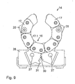
- These gear contours 30, which are embodied identically in all exemplary embodiments, are best used in the illustrations according to FIGS Fig. 7 to 10 out. It can also be seen from these illustrations that in one of the support arms 26 the last tooth 31 of the toothed wheel contour 30 is extended relative to the other teeth. It forms in this way a stop with the associated other support arm 26. With this stop, the maximum opening angle between the support arms 26 is fixed. This angle is defined so that even with the largest pipe diameter which can be moved on the extrusion line, a minimum wrap angle of the pipe circumference through the pipe support 14 of at least 120 ° is ensured.
- the starting point is the largest pipe diameter drivable on the extrusion line.
- the pipe support 14 then has the in the Fig. 2 and 3 illustrated setting. As in connection with the Fig. 7 and 8th shows, the stops 31 of the support arms 26 abut the respectively associated other support arm 26. This setting guarantees that the pipe 5 to be supported is supported at least to a partial circumference of 120 °.
- the extruded tube 5 rests on the rollers 19 and 20 and experiences by this a sufficient support for rolling friction.
- only one link chain 15 can be used with at least two levels arranged chain links 17 instead of two spaced hinge link chains 15. In this case it may be sufficient, with chain links 17 arranged only at a few levels, to provide the support arms 26 only on one side, that is, with respect to the plane of the drawing, in front of or behind the link chain 15.
- Fig. 11 is schematically illustrated the process when adjusting the pipe support 14.
- the extrusion line is changed during operation from the smallest to moving nominal diameter d1 to the largest to be driven nominal diameter d2, wherein a Arrow 32 symbolizes the extrusion direction.
- a conical pipe transition piece 5.1 results between the two nominal diameters d1 and d2.
- Fig. 11 It can be seen that the tube support 14, the extruded tube 5 at the smallest to be driven nominal diameter d1 completely, ie 360 ° of its circumference surrounds. Due to the conversion to the nominal diameter d2, the diameter increases in the pipe transition piece 5.1, so that the pipe support 14 is pressed successively.
- Fig. 11 is shown in the central representation of the tube support 14, a transition stage, while in the right figure, the support of the extruded tube 5 is shown at the largest to be driven nominal diameter d2.
Abstract
Description
- Die vorliegende Erfindung betrifft eine Vorrichtung und ein Verfahren zur Unterstützung von Rohren in Extrusionslinien gemäß dem Oberbegriff des Anspruchs 1 bzw. des Anspruchs 7.
- Eine gattungsgemäße Vorrichtung ist aus der
DE 10 2007 007 196 A1 bekannt. Die einzelnen Glieder dieser Gliederkette besitzen eine im Betrieb an einem extrudierten Rohr anliegende Stützfläche und eine dieser gegenüberliegende Keilfläche. Die Keilflächen stützen sich jeweils auf Gegenkeilflächen eines Grundrahmens ab. Zur Anpassung an die gefahrene Rohrdimension sind die Keilflächen auf den Gegenkeilflächen verschiebbar, so dass die Gliederkette insgesamt radial verlagert wird. Die Glieder sind im Bereich der Längsseiten ihrer Stützflächen über Filmscharniere oder Klavierbänder gelenkig miteinander verbunden. - Bei der oben beschriebenen Vorrichtung erfolgt die Verstellung der Rohrunterstützung von einem Nenndurchmesser auf einen anderen Nenndurchmesser im laufenden Betrieb der Extrusionslinie in dem diese aktiv, z.B. motorisch angetrieben wird. Das trifft beispielsweise auch auf die aus der
DE 10 2005 028 086 A1 und derDE 10 2004 059 515 B3 bekannten Vorrichtungen zu. - In der
WO 2004/106034 ist eine Kombirolle zur Rohrunterstützung beschrieben, die mit Mitteln, insbesondere Federmitteln, ausgestattet ist, welche dafür sorgen, dass sich die Rolle bei zunehmender Belastung durch das abzustützende Rohr nach unten bewegt und umgekehrt. Diese Lösung hat den Nachteil, dass nur für jeweils einen bestimmten Rohrdurchmesser eine optimale Abstützung vorliegt. Daher ist vorgesehen, mehrere Rollen mit unterschiedlicher Geometrie hintereinander anzuordnen. - Aufgabe der vorliegenden Erfindung ist es, eine weitere gattungsgemäße Vorrichtung sowie ein Verfahren zum Verstellen von Rohrunterstützungen zur Verfügung zu stellen.
- Diese Aufgabe wird erfindungsgemäß mit einer Vorrichtung zur Unterstützung von Rohren in Extrusionslinien gelöst, die die Merkmale des Anspruchs 1 aufweist bzw. mit einem Verfahren gemäß Anspruch 7.
- Aufgrund der an den Enden der Kettenglieder vorgesehenen, miteinander kämmenden Zahnradkonturen ist sicher gestellt, dass sich die Winkelstellungen der einzelnen Kettenglieder zueinander bei Verstellung identisch ändern. Dadurch ist es möglich, die Gelenkgliederkette an unterschiedliche Rohrdurchmesser anzupassen, wobei sich der Umschlingungswinkel dahingehend ändert, dass er bei größeren Rohrdurchmessern kleiner und bei kleineren Rohrdurchmessern größer ist. Dabei soll ein extrudiertes Rohr mindestens auf 120° seines Umfangs unterstützt werden.
- Da die einzelnen Ketteglieder nach Art eines Getriebes miteinander verbunden sind, ist es ausreichend, wenn an ein links und rechts vom Scheitelpunkt der Gelenkgliederkette angeordnetes Kettenglied jeweils eine Abstützung angreift. Dabei kann die Abstützung der Gelenkgliederkette selbsttätig oder zwangsgesteuert auf die jeweiligen gefahrenen Rohrdurchmesser eingestellt werden. Wenn die Kette zwischen den Abstützpunkten schwerer ist als zwischen den Abstützpunkten und den Enden der Ketten, verstellt sich die Gelenkgliederkette unter Schwerkraftwirkung automatisch auf einen kleineren Durchmesser, wenn z.B. in der Extrusionslinie von einem größeren Durchmesser auf einen kleineren Durchmesser umgestellt wird. Bei einem Dimensionswechsel im laufenden Betrieb ergibt sich zwischen einem zuvor gefahrenen großen Nenndurchmesser und einem anschließend zu fahrenen kleineren Nenndurchmesser ein konisches Übergangsstück mit kleiner werdendem Durchmesser, so dass die Gelenkgliederkette unter Schwerkraftwirkung selbsttätig sukzessiv "zufährt". Im umgekehrten Fall, also beim Übergang von einem kleineren gefahrenen Rohrdurchmesser auf einen größeren zu fahrenden Rohrdurchmesser drückt das ebenfalls konische Übergangsstück aufgrund des dann größer werdenden Durchmessers die Gelenkgliederkette entgegen der Schwerkraft auseinander, so dass diese sich selbsttätig auf den neuen Durchmesser einstellt. Anstelle dieser selbsttätigen Einstellung der Gelenkgliederkette kann auch eine zwangsgesteuerte Verstellung der Gelenkgliederkette vorgesehen sein, z.B. dadurch, dass mindestens eine der Abstützungen als Aktuator, z.B. als Hydraulikzylirider ausgebildet ist.
- Im einfachsten Fall bilden die dem extrudierten Rohr zugewandten Stirnflächen der Kettenglieder eine Gleitfläche für das Rohr, d.h. das extrudierte Rohr liegt direkt auf den Kettengliedern auf.
- Um die Reibung zwischen der Rohrunterstützung und dem extrudierten Rohr zu reduzieren ist in vorteilhafter Ausgestaltung der Erfindung vorgesehen, die Gelenkgliederkette mit Rollen auszustatten, so dass anstelle der Gleitreibung eine Rollreibung vorliegt. Das hat auch den Vorteil, dass die Rohrunterstützung beim Übergang von einem kleineren zu fahrenden Durchmesser auf einen größeren zu fahrenden Durchmesser leichter auseinander gedrückt wird.
- Die Erfindung wird nachstehend anhand von Ausführungsbeispielen näher erläutert. In der dazugehörigen Zeichnung zeigt:
- Fig. 1
- eine Seitenansicht einer Rohrextrusionslinie
- Fig. 2
- eine perspektivische Ansicht einer erfindungsgemäßen Vor- richtung gemäß einer ersten Ausführungsform der Erfindung, wobei die Vorrichtung auf einen großen Rohrdurchmesser eingestellt ist,
- Fig. 3
- eine Draufsicht auf die Darstellung gemäß
Fig. 2 , - Fig. 4
- eine Darstellung gemäß
Fig. 2 bei auf einen kleinen Rohr- durchmesser eingestellter Vorrichtung, - Fig. 5
- eine Draufsicht auf die Darstellung gemäß
Fig. 4 , - Fig. 6
- eine vergrößerte Einzelheit der Darstellung gemäß den
Fig. 2 bis 5 mit zwei sich überlappenden Kettengliedern, - Fig. 7
- eine Vorrichtung gemäß einer zweiten Ausführungsform der Erfindung in Vorderansicht, wobei die Vorrichtung auf einen großen Rohrdurchmesser eingestellt ist und die vorderen Stützarme der Vorrichtung weggelassen wurden,
- Fig. 8
- eine Darstellung gemäß
Fig. 7 mit dargestellten vorderen Stützarmen, - Fig. 9
- eine Darstellung gemäß
Fig. 7 bei auf einen kleineren Rohr- durchmesser eingestellter Vorrichtung, - Fig. 10
- eine Darstellung gemäß
Fig. 9 mit dargestellten vorderen Stützarmen, und - Fig. 11
- eine Prinzipdarstellung der Verstellung der Rohrunterstüt- zung.
- Die in
Fig. 1 dargestellte Extrusionslinie umfasst eine Extrudereinheit 1 mit einem Aufgabetrichter 2, einer aus der Zeichnung nicht ersichtlichen Extruderschnecke mit einem Rohrkopf 3. Über den Aufgabetrichter 2 wird ein thermoplastischer Kunststoff 4 in Granulat- oder Pulverform der Extrudereinheit 1 zugeführt. In dieser wird das Granulat bzw. Pulver erwärmt, geknetet und plastifiziert. Anschließend wird der Kunststoff 4 als formbare Masse von der Extruderschnecke in den Rohrkopf 3 gefördert und dort durch einen ringförmigen Austrittsspalt gedrückt. - Nach dem Austritt aus dem Rohrkopf 3 wird das heiße, noch verformbare Rohr 5 mittels eines am Ende der Extrusionslinie angeordneten Raupenabzugs 6 durch eine Kalibrier- und Kühleinheit 7 gezogen, die einen Vakuumtank 8 mit einer an dessem Eingang angeordneten Kalibrierhülse 9 aufweist. In der stufenlos im Durchmesser einstellbaren Kalibrierhülse 9 wird das extrudierte, noch formbare Rohr 5 auf den gewünschten Durchmesser fixiert. Nach dem Verlassen der Kalibrier- und Kühleinheit 7 tritt das Rohr 5 in eine Kühlstrecke 10 ein, in der es auf Raumtemperatur abgekühlt wird. Zwischen der Kühlstrecke 10 und dem Raupenabzug 6 ist ein Ultraschallscanner 7 angeordnet, mit dem der Durchmesser und die Wandstärke des extrudierten Rohres 5 erfasst werden. Dem Raupenabzug 6 schließt sich eine Trennsäge 12 an, mit der das Rohr 5 abgelängt wird. Des weiteren sind in der Rohrextrusionslinie Dichtungen 13 vorgesehen, die das durchlaufende Rohr 5 abdichtend umschließen.
- Da das extrudierte Rohr 5 erst nach Verlassen der Kühlstrecke 10 ausgehärtet, d.h. formstabil ist, muss es zuvor abgestützt werden, um ein Durchhängen und damit ein Deformieren zu vermeiden. Dazu sind in der Kalibrier- und Kühleinheit 7 eine und in der Kühlstrecke 10 zwei Rohrunterstützungen 14 vorgesehen, deren Aufbau und Wirkungsweise nachstehend anhand der
Figuren 2 bis 10 , die zwei verschiedenen Ausführungsformen der Erfindung zeigen, näher erläutert wird. - Die in den
Figuren 2 bis 6 gezeigte Rohrunterstützung 14 weist zwei Gelenkgliederketten 15 auf, die durch Kettenbolzen 16 parallel zueinander beabstandet angeordnet sind. Jede Gelenkgliederkette 15 weist in zwei Ebenen angeordnete Kettenglieder 17 auf, die sich von Ebene zu Ebene überlappen. Die Kettenbolzen 16 sind in den Überlappungsbereichen im Durchmesser reduziert, wie am besten ausFig. 6 hervorgeht und bilden die gelenkigen Verbindungen zwischen den Kettengliedern 17 in deren Überlappungsbereichen. Die Kettenglieder 17 jeder Ebene sind an ihren, einander zugewandeten Enden mit identischen Zahnradkonturen 18 versehen, wobei die zur gleichen Ebene gehörenden Kettenglieder 17 miteinander kämmen. - Zwischen den beiden Gelenkgliederketten 15 sind zwei Reihen von Rollen 19 bzw. 20 angeordnet, wobei die Rollen 19 der einen Reihe auf Lücke zu den Rollen 20 der anderen Reihe angeordnet sind. Dabei sind die Rollen 19 jeweils im Bereich der Zahnradkonturen 18 der inneren Kettengliedern 17, also zwischen diesen und die Rollen 20 jeweils mittig zu den inneren Kettengliedern 17 angeordnet. Diese Anordnung verlangt unterschiedliche Lagerungen der Rollen 19 und 20. So können die Rollen 19 wegen der sich ändernden Winkelstellung zwischen zwei benachbarten Kettengliedern 17 während der Verstellung der Rohrunterstützung 14 nicht direkt an diesen Kettengliedern 17 gelagert werden. Die Rollen 19 sind daher an den Kettenbolzen 16 gelagert, wie am besten aus
Fig. 6 hervorgeht. Dazu ragen von jeweils zwei benachbarten Kettenbolzen 16 Stehbolzen 21 senkrecht nach oben, an denen die Drehachsen 22 der Rollen 19 gelagert sind. Die Rollen 20 sind direkt an den zugeordneten Kettengliedern 17 gelagert. Dazu ragen von den Kettengliedern 17 parallel zu den Kettenbolzen 16 angeordnete Stehbolzen 23 nach innen ab, an denen die Drehachsen 24 der Rollen 20 gelagert sind. Da die Rollen 20 ebenso wie die Rollen 19 durch das zu unterstützende Rohr 5 auf Druck belastet werden, werden die dadurch auf Biegung beanspruchten Stehbolzen 23 über an ihren Enden vorgesehene Stützbeine 25 an den stabilen Kettenbolzen 16 abgestützt. - Die Rollen 19 und 20 sind so gelagert, dass sie die Stirnflächen 17.1 der Kettenglieder 17 nach oben überragen. Dadurch dienen die Umfangsfläche 19.1 bzw. 20.1 als Rollflächen für das in der Extrusionslinie abzustützende Rohr 5.
- Neben den oben beschriebenen Bauteilen weist die Rohrunterstützung 14 weiterhin zwei Paare von Stützarmen 26 auf, die an ihren unteren Enden über Drehgelenke 27 schwenkbar an Lagerschildern 28 gelagert sind. Die oberen Enden der Stützarme 26 sind über Distanzbolzen 29 mit den jeweils vorletzten Kettengliedern 17 der Gelenkgliederketten 15 drehgelenkig verbunden.
- Im Bereich ihrer unteren Enden sind die Stützarme 26 jeweils mit einer Zahnradkontur 30 versehen, die konzentrisch zu den Drehachsen 27 angeordnet ist. Diese Zahnradkonturen 30 kämmen miteinander. Dadurch ist gewährleistet, dass die beiden Stützarme 26 sich immer synchron bewegen. Diese bei allen Ausführungsbeispielen identisch ausgeführten Zahnradkonturen 30 gehen am besten aus den Darstellungen gemäß den
Fig. 7 bis 10 hervor. Aus diesen Darstellungen ist auch ersichtlich, dass bei einem der Stützarme 26 der letzte Zahn 31 der Zahnradkontur 30 gegenüber den anderen Zähnen verlängert ist. Er bildet auf diese Weise einen Anschlag mit dem zugeordneten anderen Stützarm 26. Mit diesem Anschlag ist der maximale Öffnungswinkel zwischen den Stützarmen 26 festgelegt. Dieser Winkel ist so definiert, dass auch bei dem größten auf der Extrusionslinie fahrbaren Rohrdurchmesser ein Mindestumschlingungswinkel des Rohrumfangs durch die Rohrunterstützung 14 von mindestens 120° gewährleistet ist. - Die Arbeitsweise der oben beschriebenen Rohrunterstützung 14 wird nachstehend für Umstellungen der Rohrextrusionslinie von einem Nenndurchmesser auf einen anderen Nenndurchmesser eines zu produzierenden Rohres 5 bei laufendem Betrieb beschrieben.
- Ausgangspunkt ist der größte auf der Extrusionslinie fahrbare Rohrdurchmesser. Die Rohrunterstützung 14 hat dann die in den
Fig. 2 und3 dargestellte Einstellung. Wie in Verbindung mit denFig. 7 und8 hervorgeht, liegen die Anschläge 31 der Stützarme 26 an dem jeweils zugeordneten anderen Stützarm 26 an. Mit dieser Einstellung ist garantiert, dass das zu unterstützende Rohr 5 mindestens auf einen Teilumfang von 120° unterstützt wird. Das extrudierte Rohr 5 liegt auf den Rollen 19 und 20 auf und erfährt durch diese eine ausreichende Abstützung bei Rollreibung. - Wenn nun die Extrusionslinie auf einen kleineren zu fahrenden Nenndurchmesser eines zu produzierenden Rohres 5 eingestellt wird, ergibt sich ein konisches Übergangsstück mit sukzessiv abnehmendem Durchmesser. Die Rohrunterstützung 14 folgt dieser Durchmesseränderung selbsttätig bis sie letztendlich auf den kleineren zu fahrenden Durchmesser eingestellt ist. Diese selbsttätige Anpassung erfolgt durch Schwerkraftwirkung. Die zwischen den Abstützpunkten der Stützarme 26 angeordneten Kettenglieder 17, Kettenbolzen 16, Rollen 19 und 20, etc. haben nämlich ein wesentlich größeres Gesamtgewicht als die sich von den Abstützpunkten nach außen anschließenden Bauelemente der Rohrunterstützung 14. Aufgrund dieses Gewichtsunterschiedes werden die Stützarme 26 aufeinander zugeschwenkt, d.h. die Rohrunterstützung 14 fährt zu und umgibt das extrudierte Rohr kleineren Durchmessers nun auf einem größeren Umschlingungswinkel, wie aus der Darstellung gemäß
Fig. 4 in Verbindung mit den Darstellungen gemäß denFig. 9 und10 hervorgeht. Wenn die Extrusionslinie wieder auf einen größeren Durchmesser umgestellt wird, ergibt sich zwischen dem kleineren und dem zu fahrenden größeren Durchmesser wiederum ein konisches Rohrübergangsstück, diesmal mit entgegen gesetzter Konizität, d.h. der Durchmesser vergrößert sich sukzessiv. Aufgrund dieser Durchmesservergrößerung wird die Rohrunterstützung 14 entgegen der Schwerkraftwirkung solange sukzessiv aufgefahren, bis der neue Nenndurchmesser des Rohres 5 erreicht ist. Die Rohrunterstützung 14 passt sich also auch hier selbsttätig dem neu zu fahrenden Rohrdurchmesser an. - In den
Fig. 7 bis 10 in ein weiteres Ausführungsbeispiel der Erfindung erläutert. Es unterscheidet sich von dem oben stehenden Ausführungsbeispiel dadurch, dass die Rollen 19, 20 und ihre entsprechenden Lagerbauelemente zum Fortfall gekommen sind. Ein extrudiertes Rohr 5 liegt bei dieser Vorrichtung unter Gleitreibung direkt auf den Stirnflächen 17.1 der Kettenglieder 17 auf. - In einem anderen Ausführungsbeispiel der Erfindung kann anstelle von zwei voneinander beabstandeten Gelenkgliederketten 15 nur eine Gelenkgliederkette 15 mit mindestens in zwei Ebenen angeordneten Kettengliedern 17 zum Einsatz kommen. Dabei kann es ausreichend sein, bei nur in wenigen Ebenen angeordneten Kettengliedern 17 die Stützarme 26 nur auf einer Seite, d.h., bezogen auf die Zeichnungsebene, vor oder hinter der Gelenkgliederkette 15 vorzusehen.
- Anstelle der selbsttätigen Verstellung der Rohrunterstützung 14 kann auch eine zwangsgesteuerte Verstellung vorgesehen sein. Dann müssten z.B. anstelle der Stützarme 26 aktive Glieder, z.B. Hydraulikkolben zur Anwendung kommen, die die Gelenkgliederkette bzw. Kette 15 aktiv verstellen.
- In
Fig. 11 ist schematisch der Ablauf beim Verstellen der Rohrunterstützung 14 dargestellt. Bei diesem Ausführungsbeispiel wird die Extrusionslinie im laufenden Betrieb von dem kleinsten zu fahrenden Nenndurchmesser d1 auf den größten zu fahrenden Nenndurchmesser d2 umgestellt, wobei ein Pfeil 32 die Extrusionsrichtung symbolisiert. Zwischen den beiden Nenndurchmessern d1 und d2 ergibt sich ein konisches Rohrübergangstück 5.1. - Aus
Fig. 11 ist ersichtlich, dass die Rohrunterstützung 14 das extrudierte Rohr 5 bei dem kleinsten zu fahrenden Nenndurchmesser d1 vollständig, d.h. auf 360°seines Umfangs umgibt. Aufgrund der Umstellung auf den Nenndurchmesser d2 vergrößert sich der Durchmesser im Rohrübergangsstück 5.1, so dass die Rohrunterstützung 14 sukzessiv aufgedrückt wird. InFig. 11 ist in der mittigen Darstellung der Rohrunterstützung 14 ein Übergangsstadium gezeigt, während in der rechten Abbildung die Abstützung des extrudierten Rohres 5 beim größten zu fahrenden Nenndurchmesser d2 gezeigt ist. - Wenn von einem größeren auf einen kleineren Nenndurchmesser umgestellt wird, fährt die Rohrunterstützung 14 aufgrund des sich dann verringernden Durchmessers im Rohrübergangsstück 5.1 sukzessiv unter Schwerkraftwirkung zu. Sie passt sich also auch in dieser Situation selbsttätig an den neu zu fahrenden Nenndurchmesser an.
Claims (7)
- Vorrichtung zur Unterstützung von Rohren in Extrusionslinien mit einer an einen jeweilig gefahrenen Rohrdurchmesser anpassbaren Rohrunterstützung, die eine an zumindest einem Teilumfang des Rohres anliegende Gelenkgliederkette aufweist, deren Kettenglieder zum Rohr hinweisende Stirnflächen besitzen, dadurch gekennzeichnet, dass die Gelenkgliederkette (15) aus in mindestens zwei Ebenen angeordneten, sich von Ebene zu Ebene überlappenden Kettengliedern (17) besteht, die in den Überlappungsbereichen gelenkig miteinander verbunden sind, wobei die Kettenglieder (17) jeder Ebene an ihren einander zugewandten Enden identische Zahnradkonturen (30) aufweisen, die miteinander kämmen.
- Vorrichtung nach Anspruch 1, dadurch gekennzeichnet, dass auf beiden Seiten des Scheitelpunkts der Gelenkgliederkette (15) jeweils eine Abstützung (26) an ein Kettenglied (17) angreift.
- Vorrichtung nach Anspruch 2, dadurch gekennzeichnet, dass sich die Abstützung (26) der Gelenkgliederkette (15) selbstätig oder zwangsgesteuert auf den jeweils gefahrenen Rohrdurchmesser einstellt bzw. eingestellt wird.
- Vorrichtung nach einem der vorstehenden Ansprüche, dadurch gekennzeichnet, dass mindestens zwei Gelenkgliederketten (15) mit mindestens in zwei Ebenen angeordneten Kettengliedern (17) durch Kettenbolzen (16) parallel zueinander beabstandet sind.
- Vorrichtung nach einem der vorstehenden Ansprüche, dadurch gekennzeichnet, dass die zum extrudierten Rohr (5) hin weisenden Stirnflächen (17.1) der Kettenglieder (17) als Gleitflächen für das Rohr (5) ausgebildet sind.
- Vorrichtung nach einem der vorstehenden Ansprüche 1 bis 4, dadurch gekennzeichnet, dass die Gelenkgliederkette (15) bzw. die Gelenkgliederketten (15) mit Rollen (19, 20) ausgestattet ist bzw. sind, deren Drehachsen (22, 24) parallel zu den Kettengliedern (17) angeordnet sind, und die die Stirnflächen (17.1) der Kettenglieder (17) zur Bildung von Rollflächen für das anliegende extrudierte Rohr (5) überragen.
- Verfahren zum Verstellen einer Rohrunterstützung in einer auf einen Dimensionswechsel im laufenden Betrieb ausgelegten Extrusionslinie, dadurch gekennzeichnet, dass das Verstellen der Rohrunterstützung (14) von einem Nenndurchmesser auf einen anderen Nenndurchmesser durch die Druckwirkung des bei einem Dimensionswechsel entstehenden konischen Rohrübergangsstücks (5.1) auf die Rohrunterstützung (14) erfolgt, wobei sich der Umschlingungswinkel der Rohrunterstützung (14) an dem abzustützenden Rohr (5) sukzessiv ändert.
Applications Claiming Priority (1)
| Application Number | Priority Date | Filing Date | Title |
|---|---|---|---|
| DE102009023438A DE102009023438A1 (de) | 2009-05-30 | 2009-05-30 | Vorrichtung und Verfahren zur Unterstützung von Rohren in Extrusionslinien |
Publications (2)
| Publication Number | Publication Date |
|---|---|
| EP2255946A1 true EP2255946A1 (de) | 2010-12-01 |
| EP2255946B1 EP2255946B1 (de) | 2016-05-18 |
Family
ID=42782134
Family Applications (1)
| Application Number | Title | Priority Date | Filing Date |
|---|---|---|---|
| EP10004841.2A Not-in-force EP2255946B1 (de) | 2009-05-30 | 2010-05-07 | Vorrichtung zur Unterstützung von Rohren in Extrusionslinien |
Country Status (6)
| Country | Link |
|---|---|
| US (1) | US8607610B2 (de) |
| EP (1) | EP2255946B1 (de) |
| CN (1) | CN101982308B (de) |
| AU (1) | AU2010202164A1 (de) |
| CA (1) | CA2705663A1 (de) |
| DE (1) | DE102009023438A1 (de) |
Cited By (4)
| Publication number | Priority date | Publication date | Assignee | Title |
|---|---|---|---|---|
| EP2546045A1 (de) | 2011-07-13 | 2013-01-16 | Wavin B.V. | Vorrichtung und Verfahren zur Unterstützung von Kunststoffprofilen in einer Extrusionslinie |
| USD731569S1 (en) | 2012-07-24 | 2015-06-09 | Nordischer Maschinenbau Rud. Baader Gmbh + Co. Kg | Sprocket for chain link |
| USD734590S1 (en) | 2012-07-24 | 2015-07-14 | Nordischer Maschinenbau Rud. Baader Gmbh + Co. Kg | Chain link |
| DK178579B1 (da) * | 2012-07-24 | 2016-07-18 | Nordischer Maschb Rud Baader Gmbh + Co Kg | Kædeled, støttekæde og støtteindretning |
Families Citing this family (11)
| Publication number | Priority date | Publication date | Assignee | Title |
|---|---|---|---|---|
| WO2007138701A1 (ja) * | 2006-05-31 | 2007-12-06 | Ibiden Co., Ltd. | 把持装置、及び、ハニカム構造体の製造方法 |
| DE102010048579A1 (de) | 2010-10-18 | 2012-04-19 | Inoex Gmbh | Verfahren und Vorrichtung zum Anfahren einer Rohrextrusionslinie |
| DE102011106057A1 (de) * | 2011-06-30 | 2013-01-03 | Kraussmaffei Technologies Gmbh | Vorrichtung zum Stützen von extrudierten Kunststoffprofilen in einer Extrusionslinie |
| CN102442568B (zh) * | 2011-09-07 | 2014-06-18 | 北京世东凌云科技有限公司 | 支架稳定装置 |
| US8671536B2 (en) * | 2012-03-08 | 2014-03-18 | General Electric Company | Apparatus for installing a turbine case |
| CN104060972B (zh) * | 2013-03-21 | 2016-11-09 | 中国石油天然气集团公司 | 滚轮式旋转装炮支架 |
| CN103894439B (zh) * | 2014-04-01 | 2015-11-25 | 太原重工股份有限公司 | 一种自动化出料槽 |
| CN104289617B (zh) * | 2014-10-15 | 2016-09-14 | 长治市钜星锻压机械设备制造有限公司 | 盘管机工件出料辊道 |
| DE102017221031B3 (de) * | 2017-11-24 | 2019-02-14 | Greiner Extrusion Group Gmbh | Vorrichtung und Verfahren zum Aufstellen eines Kunststoffprofils bei der Extrusion |
| CN111824739B (zh) * | 2020-07-17 | 2022-04-19 | 缪静 | 一种机械零件翻转设备 |
| CN113334724A (zh) * | 2021-06-07 | 2021-09-03 | 安徽玉发塑业有限公司 | 一种cpvc电力套管快速成型方法 |
Citations (9)
| Publication number | Priority date | Publication date | Assignee | Title |
|---|---|---|---|---|
| GB1242441A (en) * | 1968-01-16 | 1971-08-11 | Redland Tiles Ltd | Improvements in or relating to conveyors |
| US4388061A (en) * | 1981-07-17 | 1983-06-14 | Macro Engineering Company Ltd. | Guide assembly for cylindrical plastic tubes |
| US4793470A (en) * | 1986-07-14 | 1988-12-27 | Baker International Corporation | Conveyor belt cradle assembly |
| US5038924A (en) * | 1990-10-09 | 1991-08-13 | Richwood Industries, Inc. | Impact saddle for conveyor belts |
| WO2004106034A1 (de) | 2003-05-28 | 2004-12-09 | Krauss-Maffei Kunststofftechnik Gmbh | Kombirolle für rohrextrusionsanlage |
| DE102004059515B3 (de) | 2004-12-10 | 2006-05-11 | Inoex Gmbh | Vorrichtung zur Unterstützung von extrudierten Kunststoffprofilen, insbesondere Rohren, in einer Extrusionslinie |
| DE102005028086A1 (de) | 2005-06-17 | 2006-12-28 | Cincinnati Extrusion Gmbh | Vorrichtung zum Stützen eines Kunststoffprofiles |
| DE102006044643A1 (de) * | 2006-09-21 | 2008-04-03 | Inoex Gmbh | Vorrichtung zur Unterstützung von Kunststoffprofilen |
| EP1955838A2 (de) * | 2007-02-09 | 2008-08-13 | INOEX GmbH | Vorrichtung zur Unterstützung von Kunststoffprofilen |
Family Cites Families (4)
| Publication number | Priority date | Publication date | Assignee | Title |
|---|---|---|---|---|
| US3351034A (en) * | 1964-09-29 | 1967-11-07 | Continental Can Co | Towing and cutting device |
| DE602004017724D1 (de) * | 2003-06-20 | 2008-12-24 | Par Systems Inc | Flexible halterung |
| DE102005028088A1 (de) | 2005-06-17 | 2006-12-21 | Rudolf Schaper | Wärmetausch für luftgekühlte Blockheizkraftwerke |
| DE102005031980B4 (de) * | 2005-07-08 | 2010-06-10 | Battenfeld Extrusionstechnik Gmbh | Vorrichtung zum Stützen eines Kunststoffprofiles |
-
2009
- 2009-05-30 DE DE102009023438A patent/DE102009023438A1/de not_active Ceased
-
2010
- 2010-05-07 EP EP10004841.2A patent/EP2255946B1/de not_active Not-in-force
- 2010-05-27 US US12/788,977 patent/US8607610B2/en not_active Expired - Fee Related
- 2010-05-27 CA CA2705663A patent/CA2705663A1/en not_active Abandoned
- 2010-05-27 AU AU2010202164A patent/AU2010202164A1/en not_active Abandoned
- 2010-05-28 CN CN201010519950.7A patent/CN101982308B/zh not_active Expired - Fee Related
Patent Citations (10)
| Publication number | Priority date | Publication date | Assignee | Title |
|---|---|---|---|---|
| GB1242441A (en) * | 1968-01-16 | 1971-08-11 | Redland Tiles Ltd | Improvements in or relating to conveyors |
| US4388061A (en) * | 1981-07-17 | 1983-06-14 | Macro Engineering Company Ltd. | Guide assembly for cylindrical plastic tubes |
| US4793470A (en) * | 1986-07-14 | 1988-12-27 | Baker International Corporation | Conveyor belt cradle assembly |
| US5038924A (en) * | 1990-10-09 | 1991-08-13 | Richwood Industries, Inc. | Impact saddle for conveyor belts |
| WO2004106034A1 (de) | 2003-05-28 | 2004-12-09 | Krauss-Maffei Kunststofftechnik Gmbh | Kombirolle für rohrextrusionsanlage |
| DE102004059515B3 (de) | 2004-12-10 | 2006-05-11 | Inoex Gmbh | Vorrichtung zur Unterstützung von extrudierten Kunststoffprofilen, insbesondere Rohren, in einer Extrusionslinie |
| DE102005028086A1 (de) | 2005-06-17 | 2006-12-28 | Cincinnati Extrusion Gmbh | Vorrichtung zum Stützen eines Kunststoffprofiles |
| DE102006044643A1 (de) * | 2006-09-21 | 2008-04-03 | Inoex Gmbh | Vorrichtung zur Unterstützung von Kunststoffprofilen |
| EP1955838A2 (de) * | 2007-02-09 | 2008-08-13 | INOEX GmbH | Vorrichtung zur Unterstützung von Kunststoffprofilen |
| DE102007007196A1 (de) | 2007-02-09 | 2008-08-14 | Inoex Gmbh | Vorrichtung zur Unterstützung von Kunststoffprofilen |
Cited By (6)
| Publication number | Priority date | Publication date | Assignee | Title |
|---|---|---|---|---|
| EP2546045A1 (de) | 2011-07-13 | 2013-01-16 | Wavin B.V. | Vorrichtung und Verfahren zur Unterstützung von Kunststoffprofilen in einer Extrusionslinie |
| DE102011079071A1 (de) | 2011-07-13 | 2013-01-17 | Wavin B.V. | Vorrichtung und Verfahren zur Unterstützung von Kunststoffprofilen sowie Extrusionslinie |
| USD731569S1 (en) | 2012-07-24 | 2015-06-09 | Nordischer Maschinenbau Rud. Baader Gmbh + Co. Kg | Sprocket for chain link |
| USD734590S1 (en) | 2012-07-24 | 2015-07-14 | Nordischer Maschinenbau Rud. Baader Gmbh + Co. Kg | Chain link |
| DK178579B1 (da) * | 2012-07-24 | 2016-07-18 | Nordischer Maschb Rud Baader Gmbh + Co Kg | Kædeled, støttekæde og støtteindretning |
| US10376893B2 (en) | 2012-07-24 | 2019-08-13 | Nordischer Maschinebau RUD. Baader GMBH + Co., KG | Chain link, support chain, and support device |
Also Published As
| Publication number | Publication date |
|---|---|
| DE102009023438A1 (de) | 2010-12-09 |
| EP2255946B1 (de) | 2016-05-18 |
| US20100300172A1 (en) | 2010-12-02 |
| CN101982308B (zh) | 2015-06-17 |
| CA2705663A1 (en) | 2010-11-30 |
| US8607610B2 (en) | 2013-12-17 |
| AU2010202164A1 (en) | 2010-12-16 |
| CN101982308A (zh) | 2011-03-02 |
Similar Documents
| Publication | Publication Date | Title |
|---|---|---|
| EP2255946B1 (de) | Vorrichtung zur Unterstützung von Rohren in Extrusionslinien | |
| EP1683624B1 (de) | Stufenlos einstellbare Kalibrierhülse für extrudierte Kunststoffrohre | |
| EP1669185B1 (de) | Vorrichtung zur Unterstützung von extrudierten Kunststoffprofilen, insbesondere Rohren, in einer Extrusionslinie | |
| EP0890770A2 (de) | Verbundrohr mit angeformter Rohr-Muffe und Verfahren zu dessen Herstellung | |
| EP3094466B1 (de) | Verfahren und vorrichtung zum stützen eines kunststoffprofils | |
| WO2011054715A1 (de) | Vorrichtung und verfahren zur herstellung von folienschläuchen | |
| EP0600214A1 (de) | Verfahren und Vorrichtung zur fortlaufenden Herstellung eines Verbundrohres mit einem aussen im wesentlichen glatten Abschnitt | |
| EP3124199B1 (de) | Stufenlos einstellbare kalibrierhülse für extrudierte kunststoffrohre | |
| DE3036716A1 (de) | Verfahren und vorrichtung zur herstellung einer elastfolie | |
| DE102004029498B3 (de) | Stufenlos einstellbare Kalibrierhülse für extrudierte Kunststoffrohre | |
| DE102005063041A1 (de) | Stufenlose einstellbare Kalibrierhülse für extrudierte Kunststoffrohre | |
| DE102006044643A1 (de) | Vorrichtung zur Unterstützung von Kunststoffprofilen | |
| DE102007042631A1 (de) | Schließeinheit einer Spritzgießmaschine | |
| DE102006049660B3 (de) | Vorrichtung zum Extrudieren von Hohlsträngen | |
| DE10235151B4 (de) | Haltevorrichtung für eine Extrusionsdüse | |
| EP2546045A1 (de) | Vorrichtung und Verfahren zur Unterstützung von Kunststoffprofilen in einer Extrusionslinie | |
| DE3001705C2 (de) | Zentriervorrichtung für Formwerkzeuge von Strangpressen | |
| EP1955838A2 (de) | Vorrichtung zur Unterstützung von Kunststoffprofilen | |
| DE19727495C2 (de) | Lippenrollvorrichtung | |
| EP2103221A1 (de) | Förderschneckenabschnitte | |
| DE102007050938A1 (de) | Stufenlos einstellbare Kalibrierhülse für extrudierte Kunststoffrohre | |
| EP1762362B1 (de) | Extrudergestell | |
| EP2153971A2 (de) | Extrusionslinie für Rohre aus Kunststoff | |
| DE102009035040B4 (de) | Verfahren zur fortlaufenden Herstellung eines Rohres und Vorrichtung zur Durchführung des Verfahrens | |
| EP3392080A1 (de) | Höhenverstelleinrichtung eines kraftfahrzeugsitzes sowie verfahren zur herstellung einer derartigen höhenverstelleinrichtung |
Legal Events
| Date | Code | Title | Description |
|---|---|---|---|
| PUAI | Public reference made under article 153(3) epc to a published international application that has entered the european phase |
Free format text: ORIGINAL CODE: 0009012 |
|
| AK | Designated contracting states |
Kind code of ref document: A1 Designated state(s): AL AT BE BG CH CY CZ DE DK EE ES FI FR GB GR HR HU IE IS IT LI LT LU LV MC MK MT NL NO PL PT RO SE SI SK SM TR |
|
| AX | Request for extension of the european patent |
Extension state: BA ME RS |
|
| 17P | Request for examination filed |
Effective date: 20110525 |
|
| 17Q | First examination report despatched |
Effective date: 20120223 |
|
| RIC1 | Information provided on ipc code assigned before grant |
Ipc: B65G 13/08 20060101ALN20150506BHEP Ipc: B29C 47/90 20060101ALN20150506BHEP Ipc: B29C 47/92 20060101ALN20150506BHEP Ipc: B29C 47/34 20060101AFI20150506BHEP |
|
| GRAP | Despatch of communication of intention to grant a patent |
Free format text: ORIGINAL CODE: EPIDOSNIGR1 |
|
| INTG | Intention to grant announced |
Effective date: 20151203 |
|
| GRAS | Grant fee paid |
Free format text: ORIGINAL CODE: EPIDOSNIGR3 |
|
| GRAA | (expected) grant |
Free format text: ORIGINAL CODE: 0009210 |
|
| AK | Designated contracting states |
Kind code of ref document: B1 Designated state(s): AL AT BE BG CH CY CZ DE DK EE ES FI FR GB GR HR HU IE IS IT LI LT LU LV MC MK MT NL NO PL PT RO SE SI SK SM TR |
|
| REG | Reference to a national code |
Ref country code: GB Ref legal event code: FG4D Free format text: NOT ENGLISH |
|
| REG | Reference to a national code |
Ref country code: CH Ref legal event code: EP |
|
| REG | Reference to a national code |
Ref country code: IE Ref legal event code: FG4D Free format text: LANGUAGE OF EP DOCUMENT: GERMAN Ref country code: CH Ref legal event code: NV Representative=s name: E. BLUM AND CO. AG PATENT- UND MARKENANWAELTE , CH Ref country code: AT Ref legal event code: REF Ref document number: 800043 Country of ref document: AT Kind code of ref document: T Effective date: 20160615 |
|
| REG | Reference to a national code |
Ref country code: DE Ref legal event code: R096 Ref document number: 502010011675 Country of ref document: DE |
|
| REG | Reference to a national code |
Ref country code: NL Ref legal event code: MP Effective date: 20160518 |
|
| REG | Reference to a national code |
Ref country code: LT Ref legal event code: MG4D |
|
| PG25 | Lapsed in a contracting state [announced via postgrant information from national office to epo] |
Ref country code: NL Free format text: LAPSE BECAUSE OF FAILURE TO SUBMIT A TRANSLATION OF THE DESCRIPTION OR TO PAY THE FEE WITHIN THE PRESCRIBED TIME-LIMIT Effective date: 20160518 Ref country code: LT Free format text: LAPSE BECAUSE OF FAILURE TO SUBMIT A TRANSLATION OF THE DESCRIPTION OR TO PAY THE FEE WITHIN THE PRESCRIBED TIME-LIMIT Effective date: 20160518 Ref country code: NO Free format text: LAPSE BECAUSE OF FAILURE TO SUBMIT A TRANSLATION OF THE DESCRIPTION OR TO PAY THE FEE WITHIN THE PRESCRIBED TIME-LIMIT Effective date: 20160818 Ref country code: FI Free format text: LAPSE BECAUSE OF FAILURE TO SUBMIT A TRANSLATION OF THE DESCRIPTION OR TO PAY THE FEE WITHIN THE PRESCRIBED TIME-LIMIT Effective date: 20160518 |
|
| PG25 | Lapsed in a contracting state [announced via postgrant information from national office to epo] |
Ref country code: ES Free format text: LAPSE BECAUSE OF FAILURE TO SUBMIT A TRANSLATION OF THE DESCRIPTION OR TO PAY THE FEE WITHIN THE PRESCRIBED TIME-LIMIT Effective date: 20160518 Ref country code: SE Free format text: LAPSE BECAUSE OF FAILURE TO SUBMIT A TRANSLATION OF THE DESCRIPTION OR TO PAY THE FEE WITHIN THE PRESCRIBED TIME-LIMIT Effective date: 20160518 Ref country code: HR Free format text: LAPSE BECAUSE OF FAILURE TO SUBMIT A TRANSLATION OF THE DESCRIPTION OR TO PAY THE FEE WITHIN THE PRESCRIBED TIME-LIMIT Effective date: 20160518 Ref country code: LV Free format text: LAPSE BECAUSE OF FAILURE TO SUBMIT A TRANSLATION OF THE DESCRIPTION OR TO PAY THE FEE WITHIN THE PRESCRIBED TIME-LIMIT Effective date: 20160518 Ref country code: GR Free format text: LAPSE BECAUSE OF FAILURE TO SUBMIT A TRANSLATION OF THE DESCRIPTION OR TO PAY THE FEE WITHIN THE PRESCRIBED TIME-LIMIT Effective date: 20160819 Ref country code: PT Free format text: LAPSE BECAUSE OF FAILURE TO SUBMIT A TRANSLATION OF THE DESCRIPTION OR TO PAY THE FEE WITHIN THE PRESCRIBED TIME-LIMIT Effective date: 20160919 |
|
| PG25 | Lapsed in a contracting state [announced via postgrant information from national office to epo] |
Ref country code: DK Free format text: LAPSE BECAUSE OF FAILURE TO SUBMIT A TRANSLATION OF THE DESCRIPTION OR TO PAY THE FEE WITHIN THE PRESCRIBED TIME-LIMIT Effective date: 20160518 Ref country code: CZ Free format text: LAPSE BECAUSE OF FAILURE TO SUBMIT A TRANSLATION OF THE DESCRIPTION OR TO PAY THE FEE WITHIN THE PRESCRIBED TIME-LIMIT Effective date: 20160518 Ref country code: RO Free format text: LAPSE BECAUSE OF FAILURE TO SUBMIT A TRANSLATION OF THE DESCRIPTION OR TO PAY THE FEE WITHIN THE PRESCRIBED TIME-LIMIT Effective date: 20160518 Ref country code: EE Free format text: LAPSE BECAUSE OF FAILURE TO SUBMIT A TRANSLATION OF THE DESCRIPTION OR TO PAY THE FEE WITHIN THE PRESCRIBED TIME-LIMIT Effective date: 20160518 Ref country code: SK Free format text: LAPSE BECAUSE OF FAILURE TO SUBMIT A TRANSLATION OF THE DESCRIPTION OR TO PAY THE FEE WITHIN THE PRESCRIBED TIME-LIMIT Effective date: 20160518 |
|
| REG | Reference to a national code |
Ref country code: DE Ref legal event code: R097 Ref document number: 502010011675 Country of ref document: DE |
|
| PG25 | Lapsed in a contracting state [announced via postgrant information from national office to epo] |
Ref country code: SM Free format text: LAPSE BECAUSE OF FAILURE TO SUBMIT A TRANSLATION OF THE DESCRIPTION OR TO PAY THE FEE WITHIN THE PRESCRIBED TIME-LIMIT Effective date: 20160518 Ref country code: PL Free format text: LAPSE BECAUSE OF FAILURE TO SUBMIT A TRANSLATION OF THE DESCRIPTION OR TO PAY THE FEE WITHIN THE PRESCRIBED TIME-LIMIT Effective date: 20160518 |
|
| PLBE | No opposition filed within time limit |
Free format text: ORIGINAL CODE: 0009261 |
|
| STAA | Information on the status of an ep patent application or granted ep patent |
Free format text: STATUS: NO OPPOSITION FILED WITHIN TIME LIMIT |
|
| 26N | No opposition filed |
Effective date: 20170221 |
|
| REG | Reference to a national code |
Ref country code: FR Ref legal event code: PLFP Year of fee payment: 8 |
|
| PG25 | Lapsed in a contracting state [announced via postgrant information from national office to epo] |
Ref country code: SI Free format text: LAPSE BECAUSE OF FAILURE TO SUBMIT A TRANSLATION OF THE DESCRIPTION OR TO PAY THE FEE WITHIN THE PRESCRIBED TIME-LIMIT Effective date: 20160518 |
|
| PG25 | Lapsed in a contracting state [announced via postgrant information from national office to epo] |
Ref country code: LU Free format text: LAPSE BECAUSE OF NON-PAYMENT OF DUE FEES Effective date: 20170531 |
|
| PG25 | Lapsed in a contracting state [announced via postgrant information from national office to epo] |
Ref country code: MC Free format text: LAPSE BECAUSE OF FAILURE TO SUBMIT A TRANSLATION OF THE DESCRIPTION OR TO PAY THE FEE WITHIN THE PRESCRIBED TIME-LIMIT Effective date: 20160518 |
|
| PG25 | Lapsed in a contracting state [announced via postgrant information from national office to epo] |
Ref country code: LU Free format text: LAPSE BECAUSE OF NON-PAYMENT OF DUE FEES Effective date: 20170507 |
|
| REG | Reference to a national code |
Ref country code: BE Ref legal event code: MM Effective date: 20170531 |
|
| REG | Reference to a national code |
Ref country code: FR Ref legal event code: PLFP Year of fee payment: 9 |
|
| PG25 | Lapsed in a contracting state [announced via postgrant information from national office to epo] |
Ref country code: BE Free format text: LAPSE BECAUSE OF NON-PAYMENT OF DUE FEES Effective date: 20170531 |
|
| PG25 | Lapsed in a contracting state [announced via postgrant information from national office to epo] |
Ref country code: MT Free format text: LAPSE BECAUSE OF FAILURE TO SUBMIT A TRANSLATION OF THE DESCRIPTION OR TO PAY THE FEE WITHIN THE PRESCRIBED TIME-LIMIT Effective date: 20160518 |
|
| PG25 | Lapsed in a contracting state [announced via postgrant information from national office to epo] |
Ref country code: AL Free format text: LAPSE BECAUSE OF FAILURE TO SUBMIT A TRANSLATION OF THE DESCRIPTION OR TO PAY THE FEE WITHIN THE PRESCRIBED TIME-LIMIT Effective date: 20160518 |
|
| REG | Reference to a national code |
Ref country code: DE Ref legal event code: R079 Ref document number: 502010011675 Country of ref document: DE Free format text: PREVIOUS MAIN CLASS: B29C0047340000 Ipc: B29C0048355000 |
|
| PG25 | Lapsed in a contracting state [announced via postgrant information from national office to epo] |
Ref country code: HU Free format text: LAPSE BECAUSE OF FAILURE TO SUBMIT A TRANSLATION OF THE DESCRIPTION OR TO PAY THE FEE WITHIN THE PRESCRIBED TIME-LIMIT; INVALID AB INITIO Effective date: 20100507 |
|
| PGFP | Annual fee paid to national office [announced via postgrant information from national office to epo] |
Ref country code: IE Payment date: 20190520 Year of fee payment: 10 Ref country code: IT Payment date: 20190521 Year of fee payment: 10 |
|
| PG25 | Lapsed in a contracting state [announced via postgrant information from national office to epo] |
Ref country code: BG Free format text: LAPSE BECAUSE OF FAILURE TO SUBMIT A TRANSLATION OF THE DESCRIPTION OR TO PAY THE FEE WITHIN THE PRESCRIBED TIME-LIMIT Effective date: 20160518 |
|
| PGFP | Annual fee paid to national office [announced via postgrant information from national office to epo] |
Ref country code: FR Payment date: 20190521 Year of fee payment: 10 |
|
| PGFP | Annual fee paid to national office [announced via postgrant information from national office to epo] |
Ref country code: CH Payment date: 20190523 Year of fee payment: 10 |
|
| PG25 | Lapsed in a contracting state [announced via postgrant information from national office to epo] |
Ref country code: CY Free format text: LAPSE BECAUSE OF NON-PAYMENT OF DUE FEES Effective date: 20160518 |
|
| PGFP | Annual fee paid to national office [announced via postgrant information from national office to epo] |
Ref country code: GB Payment date: 20190523 Year of fee payment: 10 Ref country code: AT Payment date: 20190517 Year of fee payment: 10 |
|
| PG25 | Lapsed in a contracting state [announced via postgrant information from national office to epo] |
Ref country code: MK Free format text: LAPSE BECAUSE OF FAILURE TO SUBMIT A TRANSLATION OF THE DESCRIPTION OR TO PAY THE FEE WITHIN THE PRESCRIBED TIME-LIMIT Effective date: 20160518 |
|
| PG25 | Lapsed in a contracting state [announced via postgrant information from national office to epo] |
Ref country code: TR Free format text: LAPSE BECAUSE OF FAILURE TO SUBMIT A TRANSLATION OF THE DESCRIPTION OR TO PAY THE FEE WITHIN THE PRESCRIBED TIME-LIMIT Effective date: 20160518 |
|
| PG25 | Lapsed in a contracting state [announced via postgrant information from national office to epo] |
Ref country code: IS Free format text: LAPSE BECAUSE OF FAILURE TO SUBMIT A TRANSLATION OF THE DESCRIPTION OR TO PAY THE FEE WITHIN THE PRESCRIBED TIME-LIMIT Effective date: 20160918 |
|
| REG | Reference to a national code |
Ref country code: AT Ref legal event code: MM01 Ref document number: 800043 Country of ref document: AT Kind code of ref document: T Effective date: 20200507 |
|
| PG25 | Lapsed in a contracting state [announced via postgrant information from national office to epo] |
Ref country code: AT Free format text: LAPSE BECAUSE OF NON-PAYMENT OF DUE FEES Effective date: 20200507 Ref country code: CH Free format text: LAPSE BECAUSE OF NON-PAYMENT OF DUE FEES Effective date: 20200531 Ref country code: LI Free format text: LAPSE BECAUSE OF NON-PAYMENT OF DUE FEES Effective date: 20200531 |
|
| GBPC | Gb: european patent ceased through non-payment of renewal fee |
Effective date: 20200507 |
|
| PG25 | Lapsed in a contracting state [announced via postgrant information from national office to epo] |
Ref country code: FR Free format text: LAPSE BECAUSE OF NON-PAYMENT OF DUE FEES Effective date: 20200531 Ref country code: GB Free format text: LAPSE BECAUSE OF NON-PAYMENT OF DUE FEES Effective date: 20200507 Ref country code: IE Free format text: LAPSE BECAUSE OF NON-PAYMENT OF DUE FEES Effective date: 20200507 |
|
| PG25 | Lapsed in a contracting state [announced via postgrant information from national office to epo] |
Ref country code: IT Free format text: LAPSE BECAUSE OF NON-PAYMENT OF DUE FEES Effective date: 20200507 |
|
| PGFP | Annual fee paid to national office [announced via postgrant information from national office to epo] |
Ref country code: DE Payment date: 20210716 Year of fee payment: 12 |
|
| REG | Reference to a national code |
Ref country code: DE Ref legal event code: R119 Ref document number: 502010011675 Country of ref document: DE |
|
| PG25 | Lapsed in a contracting state [announced via postgrant information from national office to epo] |
Ref country code: DE Free format text: LAPSE BECAUSE OF NON-PAYMENT OF DUE FEES Effective date: 20221201 |