EP2255696A1 - Cable duct - Google Patents
Cable duct Download PDFInfo
- Publication number
- EP2255696A1 EP2255696A1 EP09007083A EP09007083A EP2255696A1 EP 2255696 A1 EP2255696 A1 EP 2255696A1 EP 09007083 A EP09007083 A EP 09007083A EP 09007083 A EP09007083 A EP 09007083A EP 2255696 A1 EP2255696 A1 EP 2255696A1
- Authority
- EP
- European Patent Office
- Prior art keywords
- cable
- cable duct
- cable channel
- sleeve
- mounting surface
- Prior art date
- Legal status (The legal status is an assumption and is not a legal conclusion. Google has not performed a legal analysis and makes no representation as to the accuracy of the status listed.)
- Granted
Links
Images


Classifications
-
- A—HUMAN NECESSITIES
- A47—FURNITURE; DOMESTIC ARTICLES OR APPLIANCES; COFFEE MILLS; SPICE MILLS; SUCTION CLEANERS IN GENERAL
- A47B—TABLES; DESKS; OFFICE FURNITURE; CABINETS; DRAWERS; GENERAL DETAILS OF FURNITURE
- A47B21/00—Tables or desks for office equipment, e.g. typewriters, keyboards
- A47B21/06—Tables or desks for office equipment, e.g. typewriters, keyboards characterised by means for holding, fastening or concealing cables
Definitions
- the invention relates to a cable duct according to the preamble of claim 1.
- an improved furniture in particular an improved table with a cable channel
- a holding rail can be tilted about a pivoting axis between a suspended cabling position and a holding position extending at least substantially parallel to the cable channel.
- the cable duct In functional position, the cable duct is raised so far that virtually no further cables can be inserted or removed in the cable duct. To lay new cables or remove laid cables, the cable duct can then be brought into a lowered wiring position.
- a cable channel arrangement is for example also from the EP 1 810 595 A1 known.
- a single cable channel piece is proposed with a cable channel bottom and two cable channel walls laterally delimiting the cable channel.
- This cable duct piece is held in each case by a spiral spring device which engages in the end face region of the cable duct and is supported on the underside of the tabletop by a holding part.
- the cable duct piece can be set up at an angle, so that longitudinally extending cables can be inserted on one longitudinal side of the one-piece cable duct piece.
- the cable duct piece has a relevant partial length of the corresponding table top length.
- a generic cable channel arrangement is for example from the DE 40 14 082 A1 known.
- This cable channel can be mounted, for example, on the underside of the desk to lay here cables for electrical and electronic devices concealed. Since many desks are also designed in the manner of angle combinations, a cable channel is proposed according to the above-mentioned prior publication, which can be straight, but also angularly arranged. To avoid that in addition to straight Lucaskanalstükken angled cable duct pieces must be kept ready, a cable duct arrangement is realized according to this prior publication, in which the cable channel bottom on the one hand and provided on the two longitudinal sides of the channel side walls are formed separately to the other must be joined together to form a cross-sectionally U-like cable channel.
- the two channel side walls in this case comprise wall sections which each comprise a joint which runs perpendicular to the cable channel bottom.
- the cable channel is supported by the two, in the lateral distance from each other, mounted under the table top channel side walls.
- the cable duct arrangement according to the invention should be as flexible as possible in terms of construction and use, so that the cable duct can be laid, for example, on a tabletop underside but also on an angled or curved path according to the circumstances.
- the cable channel consists of at least two cable channel pieces, which can be linked together.
- the chaining can be done in a "straight" way.
- the individual cable duct pieces but be aligned in an angular orientation to the respective previous or subsequent cable duct piece, so that can be installed in wide areas of the cable channel of any route following.
- the concatenation takes place via plug-in pins, which can be done at the same time an angular orientation to each other by relative pivoting two adjacent cable channel pieces.
- the individual cable duct pieces can be fastened via spring-loaded fastening devices, for example on the underside of the desk top.
- the individual cable duct pieces can be displaced downwardly away from the plane of the table top underside against the force of a spring accumulator, thereby increasing the distance between the side walls of the single cable duct piece and the underside of the table top to allow the insertion or removal of cables into the cable duct of cables from the cable duct.
- the cable channel according to the invention is easy to handle by its construction and at the same time offers a number of advantages.
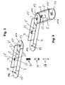
- FIG. 1 is shown in a schematic spatial representation of an embodiment of a cable duct 1 according to the invention, which is composed of three cable channel pieces 3.
- the individual cable channel pieces each have a cable channel bottom 5, which extends in the longitudinal direction of the cable duct piece, wherein in a central part length at the cable channel bottom 5 at the two longitudinal sides of the cable channel piece 3 each a cable channel side wall 7 connects , which is generally aligned transversely and in particular perpendicular to the plane of the cable channel bottom 5.
- These bottom end portions 11a, 11b are circular, disc or dish-shaped in the embodiment shown.
- the one bottom end section 11a comes via a small stepped shoulder 13 (FIG. FIG. 5 ) to the central portion 5 'of the cable channel bottom 5 to be slightly higher than the opposite second bottom end portion 11b, so that when concatenating two cable channel pieces 3 of the step shoulder 12 slightly higher end portion 11a on the next cable channel piece.
- a plug-in sleeve 13 is provided in the embodiment shown on the one bottom end piece 11a. This sits centrally in the one circular, plate-shaped or similarly formed bottom end portion 11a (which is slightly higher than the opposite bottom end portion 11b). This plug-in sleeve 13 is aligned perpendicular to the plane of the cable channel bottom 5 and is provided at the level of the cable channel bottom, ie the bottom end portion 11 a with an internal passage opening 15.
- the somewhat lower-lying bottom end portion 11a has in the illustrated embodiment, two upwardly projecting finger-like and elastically yieldable locking pin 17, which are provided at their free ends with radially mutually pioneering locking lugs 17 '.
- the concatenation is effected by a cable duct piece is placed with its bottom end portion 11 a and the receptacle 12 formed thereon on the opposite bottom end portion 11 b of a next cable channel piece 3, so that the mentioned locking pin 17, the passage opening 15 in the Pass through socket 13 of the other cable channel piece 5 and then completely overlap then with their locking lugs 17 'the upper edge 13' of the socket 13 overlap.
- the cable duct pieces 5 have in their central region 5 'on a mounting column 23 which is hollow inside and provided in its upper end portion with an inwardly projecting annular shoulder 23', whereby a passage opening
- a mounting, abutment or holding surface 26 is created by the front-side edge 26 of the fastening sleeve 23, with which a corresponding cable duct piece 3 can be fastened, for example, to a table underside 35 'of a table top 35 also to the extracts cross-sectional representation according to FIG. 6 referenced, in which an excerpt longitudinal section perpendicular to the plane of the cable channel bottom 5 by the mentioned mounting column or the mounting cylinder 23 is shown.
- the annular shoulder 23 ' is provided slightly below the overhead free end face of the mounting sleeve 23.
- a pin or cylindrical or similar spring receptacle 29 is required, as for example in FIG. 3 explosive and in FIGS. 7 and 8 can be seen in a spatial representation and in axial longitudinal section.
- This spring retainer 29 has lying down, so on the opposite side in the assembled state to the aforementioned assembly, investment or holding surface 26, a radially outwardly projecting support shoulder or a support flange 29 ', wherein the pin-shaped spring retainer 29, a coil spring 31 slid is, whose lower spring portion is supported on said support shoulder or the support flange 29 '.
- the spring is held captive on the cylindrical spring receptacle 29 as possible, adjacent to the support shoulder 29 'radially outwardly one or more holding nubs 33 may be formed, which are engaged behind by the last turn of the coil spring.
- the support shoulder or the support flange 29 'of the screw receptacle 29 thus defines in the embodiment shown a so-called mounting plane or mounting surface M, to which the cable duct pieces described can be mounted.
- This mounting plane or mounting surface M then usually coincides with the table top underside 35 'of a table top 35 when the cable ducts described there are to be mounted on such a piece of furniture.
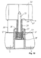
- the spring receptacle 29 thus formed is then inserted into the mounting column 23 from below via the lower opening 24 until the upper end face 29 "of the cylindrical spring receptacle 29, for example, on the underside of the table 35 'of the cable channel holding carrier, for example, a bottom 35' a Table top 35 rests, as is fundamentally from the illustration according to FIG. 9 can be seen.
- the dimensions are such that the height H of the cable channel side walls 7 is equal to or preferably smaller than the axial length of the cylindrical spring receptacle 29.
- the underside 35 'of the table top 35 thus coincides with the contact or holding surface 26 at the free end face of the mounting column 23, so that this results in a subsequently defined as a holding and / or mounting plane M level.
- the distance A1 can be zero in extreme cases, when the side wall 7 rests with its upper edge 7 'on the table top underside 35'.
- the cylindrical spring receptacle 29 is dimensioned with its outer diameter so that this outer diameter is smaller than the inner diameter of the passage opening 23 'in the annular shoulder 23' of the mounting column 23, it is now possible to take the cable duct piece in total and under compression of the coil spring 31 to press down from the table top 35, for example, starting from the in FIG. 9 shown basic position in the in FIG. 10 reproduced position.
- the effective distance A1 between the upper edge 7 'of the cable channel side wall 7 and the bottom 35' of the table top 35 is now increasingly larger, ie even so large that in this position easily and comfortably electrical cable, telephone cable, data or Computer cable etc. inserted into the interior of the cable channel 1 or appropriate cables can be led out and removed.
- the relevant cable duct piece can be released, so that under relaxation of the coil spring 31 via the force of the spring means 31, the relevant cable duct piece is then raised again in the direction of the table top 35, ie in the direction of carrier or mounting plane M until lying in the table top direction Assembly, investment or holding surface or flange 26 of the mounting sleeve 23 on the underside 35 'of the carrier, preferably in the form of the table top 35, abuts, ie on the mounting surface or - level 11th
- the adjacent cable ducts are partially depressed by pushing down the individual cable ducts, in other words pushed away from the underside of the table top, so that the insertion and removal of cables can be made very easily.
- successively adjacent cable channel pieces can also be taken and each section a cable inserted into the cable channel or removed from the cable channel.
- the respective cable channel is limited stroke so far away from the tabletop underside movable until the coil spring device is completely compressed, i. the individual turns rest on each other.
- the adjustment path should preferably be at least 5 mm, in particular at least 10 mm, 15 mm or at least 20 mm.
- the plug-in sleeve 13 also serves as a concatenation device for the concatenation of two adjacent cable channel pieces.
- the respective fastening column 23 is not centrally located in the cable duct piece, but provided on the one bottom end portion 11b, but otherwise with the same construction and design, as in the previously explained embodiment.
- the mentioned fastening sleeve 23 is used with the described construction, which then also serves as locking device 117.
- This tubular or cylindrical locking device 117 in the form of the fastening sleeve 23 interacts with the already explained in the previous embodiments at the respective second bottom end portion 11a formed plug sleeve 13, which in this embodiment, however, has an axial length corresponding to the axial length of the mounting sleeve 23 corresponds.
- Figures 11 and 12 are the corresponding axial sectional views perpendicular to the plane of the cable tray 5 reproduced for this embodiment, whereby the differences from the corresponding axial sectional views according to the Figures 9 and 10 can be seen for the previous embodiment.
- the outer diameter of the mounting sleeve 23 corresponds to the inner diameter of the receptacle 13 or is slightly smaller, so that a good pivotability between the two cable channel pieces is ensured without the frictional forces are too large or on the other hand, the game is too big.
- the concatenation of two adjacent cable channel pieces 5 causes the so formed central axis Z are pivotable relative to each other in a large angular range.
- the corresponding fastening device by the cylindrical spring receptacle 29 is introduced as in the previous embodiments, starting from the cable channel bottom in the downwardly open and plugged into the receptacle 13 from below mounting column 23 until the upper end face 26th or in this case also the annular flange 23 'is located together with the upper edge 13' of the socket 13 in the common mounting plane M, in the illustrated embodiment of the table bottom 35 'of the table top 35 abuts.
- FIG. 12 is that too FIG. 11 shown corresponding position of the cable channel when the cable channel in question is pressed down from the mounting plane M away and thereby the distance A1 between the upper edge 7 'of the cable channel side walls 7 and the mounting plane M (ie the table top bottom 35') is increased.
Abstract
Description
Die Erfindung betrifft einen Kabelkanal nach dem Oberbegriff des Anspruches 1.The invention relates to a cable duct according to the preamble of
Es ist bekannt, auf der Unterseite von Tischplatten von Büro- und Arbeitstischen Kabelkanäle vorzusehen, in denen der für die Elektrifizierung oder für die Übertragung von Daten und Informationen, zum Anschluss von PC's oder Notebooks etc. benötigte Strom und Netzwerkkabel, Telefonkabel etc. verlegt werden können.It is known to provide on the underside of table tops of office and work desks cable channels in which the power and network cables, telephone cables, etc. required for the electrification or for the transmission of data and information, for connecting PC's or notebooks, etc. are laid can.
Gemäß der
Obgleich sich dieser Kabelkanal sehr bewährt hat, ist er nur für einen gerade verlaufenden Kabelkanal geeignet.Although this cable channel has proven very successful, it is only suitable for a straight running cable channel.
Eine Kabelkanalanordnung ist beispielsweise auch aus der
Eine gattungsbildende Kabelkanalanordnung ist beispielsweise aus der
Der Kabelkanal wird dabei von den beiden, im seitlichen Abstand zueinander verlaufenden, unter der Tischplatte angebrachten Kanalseitenwänden getragen. Durch diese Konstruktion ist das Einführen von Kabeln vergleichsweise aufwändig und umständlich.The cable channel is supported by the two, in the lateral distance from each other, mounted under the table top channel side walls. By this construction, the insertion of cables is relatively complex and cumbersome.
Demgegenüber ist es Aufgabe der vorliegenden Erfindung, eine verbesserte Kabelkanalanordnung zur Montage an einem Träger zu schaffen, insbesondere zur Montage an einem Möbel oder Büromöbel, vorzugsweise an der Tischunterseite eines Arbeits- oder Schreibtisches. Dabei soll die erfindungsgemäße Kabelkanalanordnung vom Aufbau und von der Verwendung her möglichst flexibel sein, so dass der Kabelkanal beispielsweise auf einer Tischplattenunterseite gerade aber auch auf einem winkligen oder kurvigen Weg entsprechend den Gegebenheiten verlegt werden kann.In contrast, it is an object of the present invention to provide an improved cable duct assembly for mounting on a support, in particular for mounting on a piece of furniture or office furniture, preferably on the underside of a desk or work desk. In this case, the cable duct arrangement according to the invention should be as flexible as possible in terms of construction and use, so that the cable duct can be laid, for example, on a tabletop underside but also on an angled or curved path according to the circumstances.
Die Aufgabe wird erfindungsgemäß entsprechend den im Anspruch 1 angegebenen Merkmalen gelöst. Vorteilhafte Ausgestaltungen der Erfindung sind in den Unteransprüchen angegeben.The object is achieved according to the features specified in
Durch die vorliegende Erfindung wird ein völlig neuer Weg beschritten. Im Rahmen der Erfindung ist vorgesehen, dass der Kabelkanal aus zumindest zwei Kabelkanal-Stücken besteht, die miteinander verkettbar sind. Die Verkettung kann dabei auf einem "geraden" Weg vorgenommen werden. Je nach Bedarf können die einzelnen Kabelkanal-Stücke aber auch in winkliger Ausrichtung zum jeweils vorhergehenden oder nachfolgenden Kabelkanal-Stück ausgerichtet werden, so dass in weiten Bereichen der Kabelkanal einer beliebigen Strecke folgend verlegt werden kann.The present invention takes a completely new approach. In the context of the invention it is provided that the cable channel consists of at least two cable channel pieces, which can be linked together. The chaining can be done in a "straight" way. Depending on requirements, the individual cable duct pieces but be aligned in an angular orientation to the respective previous or subsequent cable duct piece, so that can be installed in wide areas of the cable channel of any route following.
In einer bevorzugten Ausführungsform der Erfindung erfolgt dabei die Verkettung über ineinander steckbare Zapfen, worüber gleichzeitig auch eine winklige Ausrichtung zueinander durch Relativ-Verschwenkung zweier benachbarter Kabelkanal-Stücke erfolgen kann.In a preferred embodiment of the invention, the concatenation takes place via plug-in pins, which can be done at the same time an angular orientation to each other by relative pivoting two adjacent cable channel pieces.
Es erweist sich ebenfalls als vorteilhaft, dass die einzelnen Kabelkanal-Stücke über federbelastete Befestigungseinrichtungen beispielsweise an der Schreibtischplatten-Unterseite befestigt werden können. Dadurch können die einzelnen Kabelkanal-Stücke entgegen der Kraft eines Federspeichers von der Ebene der Tischplattenunterseite aus nach unten weg verstellt werden, wodurch der Abstand zwischen den Seitenwänden des einzelnen Kabelkanalstückes und der Tischplattenunterseite vergrößert wird, um das Einführen von Kabeln in den Kabelkanal oder das Herausnehmen von Kabeln aus dem Kabelkanal zu erleichtern.It also proves to be advantageous that the individual cable duct pieces can be fastened via spring-loaded fastening devices, for example on the underside of the desk top. As a result, the individual cable duct pieces can be displaced downwardly away from the plane of the table top underside against the force of a spring accumulator, thereby increasing the distance between the side walls of the single cable duct piece and the underside of the table top to allow the insertion or removal of cables into the cable duct of cables from the cable duct.
Der erfindungsgemäße Kabelkanal ist durch seine Konstruktion einfachst zu handhaben und bietet dabei gleichzeitig eine Reihe von Vorteilen.The cable channel according to the invention is easy to handle by its construction and at the same time offers a number of advantages.
Die Erfindung wird nachfolgend anhand von Ausführungsbeispielen näher erläutert. Dabei zeigen im Einzelnen:
- Figur 1 :
- eine schematische räumliche Darstellung eines erfindungsgemäßen Kabelkanals unter Verwendung von drei miteinander verkette- ten Kabelkanalstücken;
- Figur 2a :
- eine Draufsicht auf das Ausführungsbei- spiel gemäß
Figur 1 - Figur 2b :
- eine Seitenansicht auf das Ausführungsbei- spiel gemäß
Figur 2a ; - Figur 3 :
- eine vergrößerte räumliche Darstellung eines einzelnen erfindungsgemäßen Kabelkanal-Stückes einschließlich der zu- gehörigen Befestigungseinrichtung in ex- plosionsartiger Darstellung;
- Figur 4 :
- zwei winklig miteinander verkettete Kabelkanal-Stücke eines erfindungsgemäßen Ausführungsbeispiels in räumlicher Dar- stellung;
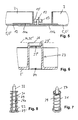
- Figur 5 :
- eine auszugsweise Querschnittsdarstellung zweier miteinander verkettete Kabelkanal- Stücke, bei denen der eine Boden-Endab- schnitt des Kabelkanal-Stückes mit leich- ten Stufenabsatz auf dem Kabel-End- abschnitt des nächsten Kabelkanal-Stückes aufliegt;
- Figur 6 :
- eine schematische axiale Querschnittsdar- stellung durch ein Kabelkanalstück senk- recht zur Bodenfläche im Bereich des einen Kabel-Endabschnittes mit einer dort vor- gesehenen im Schnitt gezeigten Befesti- gungshülse für die Verkettung mit einem nächsten Kabelkanalstück;
- Figur 7 :
- eine räumliche Darstellung der erfindungs- gemäßen Befestigungseinrichtung mit da- zugehöriger Federeinrichtung;
- Figur 8 :
- eine axiale Längsschnittdarstellung durch die Befestigungseinrichtung, wie sie in
Figur 5 - Figur 9 :
- eine axiale Längsschnittdarstellung durch einen Ausschnitt eines erfindungsgemäßen Kabelkanal-Stückes mit zugehöriger Befes- tigungseinrichtung im montierten Zustand an der Unterseite einer Tischplatte;
- Figur 10 :
- eine entsprechende Darstellung zu
Figur 7 - Figur 11 :
- eine ausschnittsweise, axiale Quer- schnittsdarstellung durch zwei miteinander verketteter Kabelkanal-Stücke und die im Verkettungsbereich vorgesehene Befesti- gungseinrichtung im montierten Zustand bei einem abgewandelten Ausführungsbeispiel; und
- Figur 12 :
- eine entsprechende Darstellung zu
Figur 11 bei entgegen der Kraft der Federspeicher- einrichtung von der Tischplattenunterseite herabgedrückten Kabelkanal-Stücken, um in den Kabelkanal Kabel leichter einzuführen oder herauszunehmen.
- FIG. 1:
- a schematic spatial representation of a cable channel according to the invention using three interconnected th cable duct pieces;
- FIG. 2a:
- a plan view of the Ausführungsbei- game according to
FIG. 1 ; - FIG. 2b:
- a side view of the exemplary embodiment according to
FIG. 2a ; - FIG. 3:
- an enlarged spatial representation of a single cable duct piece according to the invention including the associated fastening device in explosionsartiger representation;
- FIG. 4:
- two cable duct pieces of an embodiment according to the invention which are linked at an angle to one another in a spatial representation;
- FIG. 5:
- an excerpts cross-sectional view of two interconnected Kabelkanal- pieces in which one bottom end portion of the cable duct piece with a light stepped shoulder rests on the cable end portion of the next cable duct piece;
- FIG. 6:
- a schematic axial cross-sectional view through a cable duct piece perpendicular to the bottom surface in the region of the one cable end portion with a there provided in section fastening sleeve for concatenation with a next cable duct piece;
- FIG. 7:
- a spatial representation of the inventive fastening device with associated spring means;
- FIG. 8:
- an axial longitudinal section through the fastening device, as in
FIG. 5 is shown; - FIG. 9:
- an axial longitudinal section through a section of a cable duct piece according to the invention with associated fastening device in the mounted state on the underside of a table top;
- FIG. 10:
- a corresponding representation too
FIG. 7 in which, however, the cable duct piece in question is pushed away from the underside of the tabletop counter to the force of the spring device of the fastening device in order to be able to insert or remove cables more easily; - FIG. 11:
- a fragmentary, axial cross-sectional view through two interconnected cable channel pieces and provided in the concatenation fastening device in the assembled state in a modified embodiment; and
- FIG. 12:
- a corresponding representation too
FIG. 11 in contrary to the force of the spring-loaded device pressed down from the table top underside cable duct pieces to introduce easier in the cable channel or remove cables.
In
Bereits aus der räumlichen Darstellung gemäß
Wie sich insbesondere aus der weiteren Darstellung gemäß
Wie aus den Zeichnungen zu ersehen ist, weisen die Kabelkanal-Stücke 3 in Längsrichtung versetzt zueinander liegend (also in der Richtung, in der die Kabel verlegt werden sollen) Boden-Endabschnitte 11a, 11b auf, die einen Verkettungsbereich 11 bilden, auf den nachfolgend noch genauer eingegangen wird. Diese Boden-Endabschnitte 11a, 11b sind im gezeigten Ausführungsbeispiel kreis-, scheiben- oder tellerförmig gestaltet. Dabei kommt der eine Boden-Endabschnitt 11a über einen kleinen Stufenabsatz 13 (
Um zwei aufeinander folgende Kabelkanal-Stücke 3 zu verketten, ist im gezeigten Ausführungsbeispiel an dem einen Boden-Endstück 11a eine Steckhülse 13 vorgesehen. Diese sitzt zentrisch in dem einen kreis-, tellerförmig oder ähnlich ausgebildeten Boden-Endabschnitt 11a (der etwas höher liegt als der gegenüberliegende Boden-Endabschnitt 11b). Diese Steckhülse 13 ist senkrecht zur Ebene des Kabelkanalbodens 5 ausgerichtet und ist in Höhe des Kabelkanalbodens, d.h. des Boden-Endabschnittes 11a mit einer innen liegenden Durchtrittsöffnung 15 versehen.In order to concatenate two consecutive
Der etwas tiefer liegende Boden-Endabschnitt 11a weist im gezeigten Ausführungsbeispiel zwei nach oben vorstehende fingerartige und elastisch nachgebbare Arretierzapfen 17 auf, die an ihren freien Enden mit radial voneinander wegweisenden Rastansätzen 17' versehen sind. Die Verkettung wird dadurch bewirkt, dass ein Kabelkanal-Stück mit seinem Boden-Endbereich 11a und der dort ausgebildeten Steckhülse 12 auf den gegenüberliegenden Boden-Endbereich 11b eines nächsten Kabelkanal-Stückes 3 aufgesetzt wird, so dass die erwähnten Rastzapfen 17 die Durchtrittsöffnung 15 in der Steckhülse 13 des anderen Kabelkanal-Stückes 5 durchgreifen und beim völligen Aufsetzen dann mit ihren Rastansätzen 17' den oben liegenden Rand 13' der Steckhülse 13 übergreifen.The somewhat lower-lying bottom end portion 11a has in the illustrated embodiment, two upwardly projecting finger-like and elastically
Wie aus den Zeichnungen auch zu ersehen ist, weisen die Kabelkanal-Stücke 5 in ihrem mittleren Bereich 5' eine Befestigungssäule 23 auf, die innen hohl gestaltet und in ihrem oben liegenden Endbereich mit einer nach innen vorstehenden Ringschulter 23' versehen ist, wodurch eine Durchtrittsöffnung 23" gebildet ist. Durch den stirnseitigen Rand 26 der Befestigungshülse 23 wird gleichzeitig eine Montage-, Anlage- oder Haltefläche 26 geschaffen, mit der ein entsprechendes Kabelkanal-Stück 3 beispielsweise an einer Tischunterseite 35' einer Tischplatte 35 befestigt werden kann. Es wird insoweit auch auf die auszugsweise Querschnittsdarstellung gemäß
Für die Befestigung wird ferner eine zapfen- oder zylinderförmige oder -ähnliche Federaufnahme 29 benötigt, wie sie beispielsweise in
Die so gebildete Federaufnahme 29 wird dann in die Befestigungssäule 23 von unten her über die untere Öffnung 24 eingeführt, bis die oben liegende Stirnseite 29" der zylinderförmigen Federaufnahme 29 beispielsweise an der Tischunterseite 35' eines den Kabelkanal haltenden Trägers, beispielsweise einer Unterseite 35' einer Tischplatte 35 aufliegt, wie dies grundsätzlich aus der Darstellung gemäß
In dieser Position wird dann eine, die zylinderförmige Federaufnahme 29 zentral, nämlich durch die Axialbohrung 29a, durchsetzende Schraube 37 (deren Axiallänge größer ist als die Axiallänge der zylinderförmigen Federaufnahme 29) bis in das Material des Trägers, in der Regel der Tischplatte 35, eingedreht.In this position, then, one, the
Aus der axialen Schnittdarstellung gemäß
Die Dimensionierungen sind so, dass die Höhe H der Kabelkanal-Seitenwände 7 gleich oder bevorzugt kleiner ist als die Axiallänge der zylinderförmigen Federaufnahme 29. In diesem Falle, wenn die Höhe H der Kabelkanal-Seitenwand 7 kleiner ist als die Axiallänge oder Höhe der zylinderförmigen Federaufnahme 29, ergibt sich die in der Querschnittsdarstellung gemäß
Da die zylinderförmige Federaufnahme 29 mit ihrem Außendurchmesser so bemessen ist, dass dieser Außendurchmesser kleiner ist als der Innendurchmesser der Durchtrittsöffnung 23' in der Ringschulter 23' der Befestigungssäule 23, ist es nunmehr möglich, das Kabelkanal-Stück insgesamt zu ergreifen und unter Komprimierung der Schraubenfeder 31 nach unten von der Tischplatte 35 wegzudrücken, beispielsweise ausgehend von der in
Durch die Verkettung werden zum Teil durch Herabdrücken der einzelnen Kabelkanäle auch noch die jeweils benachbarten Kabelkanäle teilweise mit herabgedrückt, also von der Tischplattenunterseite weggedrückt, so dass das Ein- und Ausführen von Kabeln sehr leicht vorgenommen werden kann. Beim Verlegen eines Kabels können dann sukzessive benachbarte Kabelkanal-Stücke ebenfalls ergriffen und jeweils abschnittsweise ein Kabel in den Kabelkanal eingeführt bzw. vom Kabelkanal herausgenommen werden. Der jeweilige Kabelkanal ist dabei anschlagsbegrenzt so weit von der Tischplattenunterseite entfernt bewegbar, bis die Schraubenfeder-Einrichtung vollständig komprimiert ist, d.h. die einzelnen Windungen aneinander aufliegen. Der Verstellweg sollte dabei vorzugsweise zumindest 5 mm, insbesondere zumindest 10 mm, 15 mm oder zumindest 20 mm betragen.Due to the chaining, the adjacent cable ducts are partially depressed by pushing down the individual cable ducts, in other words pushed away from the underside of the table top, so that the insertion and removal of cables can be made very easily. When laying a cable then successively adjacent cable channel pieces can also be taken and each section a cable inserted into the cable channel or removed from the cable channel. The respective cable channel is limited stroke so far away from the tabletop underside movable until the coil spring device is completely compressed, i. the individual turns rest on each other. The adjustment path should preferably be at least 5 mm, in particular at least 10 mm, 15 mm or at least 20 mm.
Anhand der
Mit anderen Worten wird also bei diesem Ausführungsbeispiel anstelle der in den vorausgegangenen Ausführungsbeispielen erwähnten Arretierzapfen 17 an dem einen Boden-Endabschnitt 11b die erwähnte Befestigungshülse 23 mit dem erläuterten Aufbau verwendet, die gleichzeitig dann auch als Arretiereinrichtung 117 dient. Diese rohr- oder zylinderförmige Arretiereinrichtung 117 in Form der Befestigungshülse 23 wirkt mit der bereits bei den vorausgegangenen Ausführungsbeispielen erläuterten an dem jeweils zweiten Boden-Endabschnitt 11a ausgebildeten Steckhülse 13 zusammen, die in diesem Ausführungsbeispiel allerdings eine axiale Länge aufweist, die der axialen Länge der Befestigungshülse 23 entspricht. In
Zur gleichzeitigen Verkettung zweier benachbarter Kabelkanal-Stücke wird dabei jeweils die Befestigungshülse 23 von unten her in die Steckhülse 13, die an dem anderen Boden-Endabschnitt 11a ausgebildet ist, eingeschoben, bis die beiden Kabel-Bodenabschnitte 11a, 11b zweier miteinander verketteter Kabelstücke 3 aufeinander liegen. Der Außendurchmesser der Befestigungshülse 23 entspricht dabei dem Innendurchmesser der Steckhülse 13 oder ist geringfügig kleiner, so dass eine gute Verschwenkbarkeit zwischen den beiden Kabelkanal-Stücken gewährleistet ist, ohne dass die Reibkräfte zu groß werden oder andererseits das Spiel zu groß wird. Dadurch wird zum einen die Verkettung zweier benachbarter Kabelkanal-Stücke 5 bewirkt, die um die so gebildete Zentralachse Z in einem großen Winkelbereich relativ zueinander verschwenkbar sind. Gleichzeitig kann hier die entsprechende Befestigungseinrichtung ansetzen, indem die zylinderförmige Federaufnahme 29 wie bei den vorhergehenden Ausführungsbeispielen auch von der Kabelkanal-Unterseite ausgehend in die nach unten hin offene und in die Steckhülse 13 von unten eingesteckte Befestigungssäule 23 eingeführt wird, bis die oben liegende Stirnseite 26 oder in diesem Falle auch der Ringflansch 23' gemeinsam mit dem oben liegenden Rand 13' der Steckhülse 13 in der gemeinsamen Montageebene M liegt, im gezeigten Ausführungsbeispiel an der Tischunterseite 35' der Tischplatte 35 anliegt.For simultaneous concatenation of two adjacent cable channel pieces while the mounting
Auch in diesem Ausführungsbeispiel kann dann der jeweilige Kabelkanal entgegen der Kraft der Federeinrichtung 31 (unter Komprimierung der Schraubenfeder) von der Montageebene M, also von der Tischplattenunterseite weg nach unten verstellt werden, um Kabel in den Kabelkanal einzuführen oder herauszunehmen. In
Claims (13)
Priority Applications (3)
| Application Number | Priority Date | Filing Date | Title |
|---|---|---|---|
| ES09007083T ES2369239T3 (en) | 2009-05-27 | 2009-05-27 | CHANNEL FOR CABLES. |
| EP09007083A EP2255696B1 (en) | 2009-05-27 | 2009-05-27 | Cable duct |
| AT09007083T ATE515212T1 (en) | 2009-05-27 | 2009-05-27 | CABEL CANAL |
Applications Claiming Priority (1)
| Application Number | Priority Date | Filing Date | Title |
|---|---|---|---|
| EP09007083A EP2255696B1 (en) | 2009-05-27 | 2009-05-27 | Cable duct |
Publications (2)
| Publication Number | Publication Date |
|---|---|
| EP2255696A1 true EP2255696A1 (en) | 2010-12-01 |
| EP2255696B1 EP2255696B1 (en) | 2011-07-06 |
Family
ID=41161389
Family Applications (1)
| Application Number | Title | Priority Date | Filing Date |
|---|---|---|---|
| EP09007083A Active EP2255696B1 (en) | 2009-05-27 | 2009-05-27 | Cable duct |
Country Status (3)
| Country | Link |
|---|---|
| EP (1) | EP2255696B1 (en) |
| AT (1) | ATE515212T1 (en) |
| ES (1) | ES2369239T3 (en) |
Cited By (1)
| Publication number | Priority date | Publication date | Assignee | Title |
|---|---|---|---|---|
| US7895080B2 (en) | 2002-11-19 | 2011-02-22 | Omnicom Holdings Inc. | Apparatus and method for facilitating the selection of products by buyers and the purchase of the selected products from a supplier |
Citations (6)
| Publication number | Priority date | Publication date | Assignee | Title |
|---|---|---|---|---|
| GB2186319A (en) | 1986-02-06 | 1987-08-12 | Mines & West Ltd | Improvements in and relating to cable retaining devices |
| DE4014082A1 (en) | 1990-05-02 | 1991-11-07 | 3K Bueromoebel Gmbh | CABLE CHANNEL FOR ANGLE ELEMENTS FROM BUEROMOEBEL-ANGLE COMBINATIONS |
| US5240209A (en) | 1992-11-17 | 1993-08-31 | Telect, Inc. | Telecommunication multiple cable carrier |
| US6086028A (en) * | 1999-05-26 | 2000-07-11 | Pfister; Joel W. | Table leg with cable management system |
| EP1810595A1 (en) | 2006-01-20 | 2007-07-25 | Steelcase Sa | Cable duct to be mounted on a piece of furniture of the office type |
| WO2007128432A1 (en) | 2006-05-09 | 2007-11-15 | Steelcase Werndl Ag | Furniture with cable channel |
-
2009
- 2009-05-27 ES ES09007083T patent/ES2369239T3/en active Active
- 2009-05-27 AT AT09007083T patent/ATE515212T1/en active
- 2009-05-27 EP EP09007083A patent/EP2255696B1/en active Active
Patent Citations (6)
| Publication number | Priority date | Publication date | Assignee | Title |
|---|---|---|---|---|
| GB2186319A (en) | 1986-02-06 | 1987-08-12 | Mines & West Ltd | Improvements in and relating to cable retaining devices |
| DE4014082A1 (en) | 1990-05-02 | 1991-11-07 | 3K Bueromoebel Gmbh | CABLE CHANNEL FOR ANGLE ELEMENTS FROM BUEROMOEBEL-ANGLE COMBINATIONS |
| US5240209A (en) | 1992-11-17 | 1993-08-31 | Telect, Inc. | Telecommunication multiple cable carrier |
| US6086028A (en) * | 1999-05-26 | 2000-07-11 | Pfister; Joel W. | Table leg with cable management system |
| EP1810595A1 (en) | 2006-01-20 | 2007-07-25 | Steelcase Sa | Cable duct to be mounted on a piece of furniture of the office type |
| WO2007128432A1 (en) | 2006-05-09 | 2007-11-15 | Steelcase Werndl Ag | Furniture with cable channel |
Cited By (1)
| Publication number | Priority date | Publication date | Assignee | Title |
|---|---|---|---|---|
| US7895080B2 (en) | 2002-11-19 | 2011-02-22 | Omnicom Holdings Inc. | Apparatus and method for facilitating the selection of products by buyers and the purchase of the selected products from a supplier |
Also Published As
| Publication number | Publication date |
|---|---|
| ES2369239T3 (en) | 2011-11-28 |
| ATE515212T1 (en) | 2011-07-15 |
| EP2255696B1 (en) | 2011-07-06 |
Similar Documents
| Publication | Publication Date | Title |
|---|---|---|
| DE10021377A1 (en) | Circular connectors | |
| WO2005085658A1 (en) | Device for mutual positioning of longitudinal building components | |
| DE1490840B2 (en) | ELECTRIC PLUG-IN COUPLING FOR CONNECTING COAXIAL CABLES | |
| EP1208619B1 (en) | Electrical plug-in device | |
| DE4408985B4 (en) | Electrical device, in particular terminal block, with a terminal for a quick connection | |
| EP1919026A1 (en) | Housing for an electronic assembly, for mounting onto a motor vehicle | |
| EP2916686B1 (en) | Sliding-guide element and tabletop-fastening system for fastening a tabletop in a displaceable manner | |
| DE102008034775A1 (en) | Homogeneous power units'frames connecting device for switchgear, has adapters switching from spaced position to approximated position in approximation direction, while locking pin is inserted into one opening of fingers | |
| DE2420053A1 (en) | DEVICE FOR THE RELEASABLE CONNECTION OF AN ELECTRICAL CABLE TO THE POLE PIN OF AN ACCUMULATOR BATTERY | |
| DE19830586A1 (en) | Drinking valve for small animals | |
| EP2255696B1 (en) | Cable duct | |
| DE102020000118B4 (en) | Push-pull circular connector and connector system | |
| DE102006004176A1 (en) | Table system for conference table area, has individual table legs connected to table top by axially adjusting plug-mounting, where automatic holding device holds table leg, after leg is inserted into plug mounting | |
| EP0674375B1 (en) | Releasable coupling device between two aligned conductors | |
| DE10220879A1 (en) | Stand for clamping rod-shaped parts | |
| EP2320136A1 (en) | Installation frame with fixing device | |
| WO1991019116A1 (en) | Guide and assembly unit for a pressure spring | |
| EP1193822B1 (en) | Bus bar support | |
| EP0780070A2 (en) | Adjustable table system | |
| EP1777791A2 (en) | End piece and / or connecting piece | |
| EP2446776B1 (en) | Connection device for connecting a first and a second furniture component with a third furniture component, parts set and table | |
| DE3910812C1 (en) | ||
| EP2353443B1 (en) | Drawer guide, in particular for a vertical drawer | |
| DE102011010036A1 (en) | Device for fastening a component to a carrier component | |
| DE3507896C2 (en) |
Legal Events
| Date | Code | Title | Description |
|---|---|---|---|
| PUAI | Public reference made under article 153(3) epc to a published international application that has entered the european phase |
Free format text: ORIGINAL CODE: 0009012 |
|
| 17P | Request for examination filed |
Effective date: 20091222 |
|
| AK | Designated contracting states |
Kind code of ref document: A1 Designated state(s): AT BE BG CH CY CZ DE DK EE ES FI FR GB GR HR HU IE IS IT LI LT LU LV MC MK MT NL NO PL PT RO SE SI SK TR |
|
| AX | Request for extension of the european patent |
Extension state: AL BA RS |
|
| GRAP | Despatch of communication of intention to grant a patent |
Free format text: ORIGINAL CODE: EPIDOSNIGR1 |
|
| RIC1 | Information provided on ipc code assigned before grant |
Ipc: A47B 21/06 20060101AFI20101203BHEP |
|
| GRAS | Grant fee paid |
Free format text: ORIGINAL CODE: EPIDOSNIGR3 |
|
| GRAA | (expected) grant |
Free format text: ORIGINAL CODE: 0009210 |
|
| AK | Designated contracting states |
Kind code of ref document: B1 Designated state(s): AT BE BG CH CY CZ DE DK EE ES FI FR GB GR HR HU IE IS IT LI LT LU LV MC MK MT NL NO PL PT RO SE SI SK TR |
|
| REG | Reference to a national code |
Ref country code: GB Ref legal event code: FG4D Free format text: NOT ENGLISH |
|
| REG | Reference to a national code |
Ref country code: CH Ref legal event code: EP |
|
| REG | Reference to a national code |
Ref country code: IE Ref legal event code: FG4D Free format text: LANGUAGE OF EP DOCUMENT: GERMAN |
|
| REG | Reference to a national code |
Ref country code: DE Ref legal event code: R096 Ref document number: 502009000886 Country of ref document: DE Effective date: 20110825 |
|
| REG | Reference to a national code |
Ref country code: NL Ref legal event code: VDEP Effective date: 20110706 |
|
| REG | Reference to a national code |
Ref country code: ES Ref legal event code: FG2A Ref document number: 2369239 Country of ref document: ES Kind code of ref document: T3 Effective date: 20111128 |
|
| PG25 | Lapsed in a contracting state [announced via postgrant information from national office to epo] |
Ref country code: SI Free format text: LAPSE BECAUSE OF FAILURE TO SUBMIT A TRANSLATION OF THE DESCRIPTION OR TO PAY THE FEE WITHIN THE PRESCRIBED TIME-LIMIT Effective date: 20110706 |
|
| PG25 | Lapsed in a contracting state [announced via postgrant information from national office to epo] |
Ref country code: HR Free format text: LAPSE BECAUSE OF FAILURE TO SUBMIT A TRANSLATION OF THE DESCRIPTION OR TO PAY THE FEE WITHIN THE PRESCRIBED TIME-LIMIT Effective date: 20110706 Ref country code: NO Free format text: LAPSE BECAUSE OF FAILURE TO SUBMIT A TRANSLATION OF THE DESCRIPTION OR TO PAY THE FEE WITHIN THE PRESCRIBED TIME-LIMIT Effective date: 20111006 Ref country code: NL Free format text: LAPSE BECAUSE OF FAILURE TO SUBMIT A TRANSLATION OF THE DESCRIPTION OR TO PAY THE FEE WITHIN THE PRESCRIBED TIME-LIMIT Effective date: 20110706 Ref country code: SE Free format text: LAPSE BECAUSE OF FAILURE TO SUBMIT A TRANSLATION OF THE DESCRIPTION OR TO PAY THE FEE WITHIN THE PRESCRIBED TIME-LIMIT Effective date: 20110706 Ref country code: IS Free format text: LAPSE BECAUSE OF FAILURE TO SUBMIT A TRANSLATION OF THE DESCRIPTION OR TO PAY THE FEE WITHIN THE PRESCRIBED TIME-LIMIT Effective date: 20111106 Ref country code: PT Free format text: LAPSE BECAUSE OF FAILURE TO SUBMIT A TRANSLATION OF THE DESCRIPTION OR TO PAY THE FEE WITHIN THE PRESCRIBED TIME-LIMIT Effective date: 20111107 Ref country code: LT Free format text: LAPSE BECAUSE OF FAILURE TO SUBMIT A TRANSLATION OF THE DESCRIPTION OR TO PAY THE FEE WITHIN THE PRESCRIBED TIME-LIMIT Effective date: 20110706 Ref country code: FI Free format text: LAPSE BECAUSE OF FAILURE TO SUBMIT A TRANSLATION OF THE DESCRIPTION OR TO PAY THE FEE WITHIN THE PRESCRIBED TIME-LIMIT Effective date: 20110706 |
|
| REG | Reference to a national code |
Ref country code: IE Ref legal event code: FD4D |
|
| PG25 | Lapsed in a contracting state [announced via postgrant information from national office to epo] |
Ref country code: GR Free format text: LAPSE BECAUSE OF FAILURE TO SUBMIT A TRANSLATION OF THE DESCRIPTION OR TO PAY THE FEE WITHIN THE PRESCRIBED TIME-LIMIT Effective date: 20111007 Ref country code: LV Free format text: LAPSE BECAUSE OF FAILURE TO SUBMIT A TRANSLATION OF THE DESCRIPTION OR TO PAY THE FEE WITHIN THE PRESCRIBED TIME-LIMIT Effective date: 20110706 Ref country code: PL Free format text: LAPSE BECAUSE OF FAILURE TO SUBMIT A TRANSLATION OF THE DESCRIPTION OR TO PAY THE FEE WITHIN THE PRESCRIBED TIME-LIMIT Effective date: 20110706 Ref country code: CY Free format text: LAPSE BECAUSE OF FAILURE TO SUBMIT A TRANSLATION OF THE DESCRIPTION OR TO PAY THE FEE WITHIN THE PRESCRIBED TIME-LIMIT Effective date: 20110706 |
|
| PG25 | Lapsed in a contracting state [announced via postgrant information from national office to epo] |
Ref country code: CZ Free format text: LAPSE BECAUSE OF FAILURE TO SUBMIT A TRANSLATION OF THE DESCRIPTION OR TO PAY THE FEE WITHIN THE PRESCRIBED TIME-LIMIT Effective date: 20110706 Ref country code: IE Free format text: LAPSE BECAUSE OF FAILURE TO SUBMIT A TRANSLATION OF THE DESCRIPTION OR TO PAY THE FEE WITHIN THE PRESCRIBED TIME-LIMIT Effective date: 20110706 Ref country code: SK Free format text: LAPSE BECAUSE OF FAILURE TO SUBMIT A TRANSLATION OF THE DESCRIPTION OR TO PAY THE FEE WITHIN THE PRESCRIBED TIME-LIMIT Effective date: 20110706 |
|
| PLBE | No opposition filed within time limit |
Free format text: ORIGINAL CODE: 0009261 |
|
| STAA | Information on the status of an ep patent application or granted ep patent |
Free format text: STATUS: NO OPPOSITION FILED WITHIN TIME LIMIT |
|
| PG25 | Lapsed in a contracting state [announced via postgrant information from national office to epo] |
Ref country code: RO Free format text: LAPSE BECAUSE OF FAILURE TO SUBMIT A TRANSLATION OF THE DESCRIPTION OR TO PAY THE FEE WITHIN THE PRESCRIBED TIME-LIMIT Effective date: 20110706 Ref country code: EE Free format text: LAPSE BECAUSE OF FAILURE TO SUBMIT A TRANSLATION OF THE DESCRIPTION OR TO PAY THE FEE WITHIN THE PRESCRIBED TIME-LIMIT Effective date: 20110706 Ref country code: IT Free format text: LAPSE BECAUSE OF FAILURE TO SUBMIT A TRANSLATION OF THE DESCRIPTION OR TO PAY THE FEE WITHIN THE PRESCRIBED TIME-LIMIT Effective date: 20110706 |
|
| 26N | No opposition filed |
Effective date: 20120411 |
|
| PG25 | Lapsed in a contracting state [announced via postgrant information from national office to epo] |
Ref country code: DK Free format text: LAPSE BECAUSE OF FAILURE TO SUBMIT A TRANSLATION OF THE DESCRIPTION OR TO PAY THE FEE WITHIN THE PRESCRIBED TIME-LIMIT Effective date: 20110706 |
|
| REG | Reference to a national code |
Ref country code: DE Ref legal event code: R097 Ref document number: 502009000886 Country of ref document: DE Effective date: 20120411 |
|
| BERE | Be: lapsed |
Owner name: STEELCASE WERNDL A.G. Effective date: 20120531 |
|
| PG25 | Lapsed in a contracting state [announced via postgrant information from national office to epo] |
Ref country code: MC Free format text: LAPSE BECAUSE OF NON-PAYMENT OF DUE FEES Effective date: 20120531 |
|
| PG25 | Lapsed in a contracting state [announced via postgrant information from national office to epo] |
Ref country code: MK Free format text: LAPSE BECAUSE OF FAILURE TO SUBMIT A TRANSLATION OF THE DESCRIPTION OR TO PAY THE FEE WITHIN THE PRESCRIBED TIME-LIMIT Effective date: 20110706 Ref country code: BE Free format text: LAPSE BECAUSE OF NON-PAYMENT OF DUE FEES Effective date: 20120531 |
|
| PG25 | Lapsed in a contracting state [announced via postgrant information from national office to epo] |
Ref country code: BG Free format text: LAPSE BECAUSE OF FAILURE TO SUBMIT A TRANSLATION OF THE DESCRIPTION OR TO PAY THE FEE WITHIN THE PRESCRIBED TIME-LIMIT Effective date: 20111006 |
|
| PG25 | Lapsed in a contracting state [announced via postgrant information from national office to epo] |
Ref country code: MT Free format text: LAPSE BECAUSE OF FAILURE TO SUBMIT A TRANSLATION OF THE DESCRIPTION OR TO PAY THE FEE WITHIN THE PRESCRIBED TIME-LIMIT Effective date: 20110706 |
|
| REG | Reference to a national code |
Ref country code: CH Ref legal event code: PL |
|
| PG25 | Lapsed in a contracting state [announced via postgrant information from national office to epo] |
Ref country code: LI Free format text: LAPSE BECAUSE OF NON-PAYMENT OF DUE FEES Effective date: 20130531 Ref country code: CH Free format text: LAPSE BECAUSE OF NON-PAYMENT OF DUE FEES Effective date: 20130531 |
|
| PG25 | Lapsed in a contracting state [announced via postgrant information from national office to epo] |
Ref country code: TR Free format text: LAPSE BECAUSE OF FAILURE TO SUBMIT A TRANSLATION OF THE DESCRIPTION OR TO PAY THE FEE WITHIN THE PRESCRIBED TIME-LIMIT Effective date: 20110706 |
|
| PG25 | Lapsed in a contracting state [announced via postgrant information from national office to epo] |
Ref country code: LU Free format text: LAPSE BECAUSE OF NON-PAYMENT OF DUE FEES Effective date: 20120527 |
|
| PG25 | Lapsed in a contracting state [announced via postgrant information from national office to epo] |
Ref country code: HU Free format text: LAPSE BECAUSE OF FAILURE TO SUBMIT A TRANSLATION OF THE DESCRIPTION OR TO PAY THE FEE WITHIN THE PRESCRIBED TIME-LIMIT Effective date: 20090527 |
|
| REG | Reference to a national code |
Ref country code: FR Ref legal event code: PLFP Year of fee payment: 7 |
|
| REG | Reference to a national code |
Ref country code: AT Ref legal event code: MM01 Ref document number: 515212 Country of ref document: AT Kind code of ref document: T Effective date: 20140527 |
|
| PG25 | Lapsed in a contracting state [announced via postgrant information from national office to epo] |
Ref country code: AT Free format text: LAPSE BECAUSE OF NON-PAYMENT OF DUE FEES Effective date: 20140527 |
|
| REG | Reference to a national code |
Ref country code: DE Ref legal event code: R082 Ref document number: 502009000886 Country of ref document: DE Representative=s name: ANDRAE WESTENDORP PATENTANWAELTE PARTNERSCHAFT, DE Ref country code: DE Ref legal event code: R081 Ref document number: 502009000886 Country of ref document: DE Owner name: STEELCASE INC., GRAND RAPIDS, US Free format text: FORMER OWNER: STEELCASE WERNDL AKTIENGESELLSCHAFT, 83026 ROSENHEIM, DE Ref country code: DE Ref legal event code: R082 Ref document number: 502009000886 Country of ref document: DE Representative=s name: FLACH BAUER STAHL PATENTANWAELTE PARTNERSCHAFT, DE |
|
| REG | Reference to a national code |
Ref country code: GB Ref legal event code: 732E Free format text: REGISTERED BETWEEN 20151008 AND 20151014 |
|
| REG | Reference to a national code |
Ref country code: ES Ref legal event code: PC2A Owner name: STEELCASE INC. Effective date: 20160202 |
|
| REG | Reference to a national code |
Ref country code: FR Ref legal event code: TP Owner name: STEELCASE INC., US Effective date: 20160108 |
|
| REG | Reference to a national code |
Ref country code: FR Ref legal event code: PLFP Year of fee payment: 8 |
|
| REG | Reference to a national code |
Ref country code: FR Ref legal event code: PLFP Year of fee payment: 9 |
|
| REG | Reference to a national code |
Ref country code: FR Ref legal event code: PLFP Year of fee payment: 10 |
|
| REG | Reference to a national code |
Ref country code: DE Ref legal event code: R082 Ref document number: 502009000886 Country of ref document: DE Representative=s name: FLACH BAUER & PARTNER PATENTANWAELTE MBB, DE Ref country code: DE Ref legal event code: R082 Ref document number: 502009000886 Country of ref document: DE Representative=s name: FLACH BAUER STAHL PATENTANWAELTE PARTNERSCHAFT, DE |
|
| PGFP | Annual fee paid to national office [announced via postgrant information from national office to epo] |
Ref country code: ES Payment date: 20180601 Year of fee payment: 10 |
|
| REG | Reference to a national code |
Ref country code: ES Ref legal event code: FD2A Effective date: 20201001 |
|
| PG25 | Lapsed in a contracting state [announced via postgrant information from national office to epo] |
Ref country code: ES Free format text: LAPSE BECAUSE OF NON-PAYMENT OF DUE FEES Effective date: 20190528 |
|
| PGFP | Annual fee paid to national office [announced via postgrant information from national office to epo] |
Ref country code: FR Payment date: 20230525 Year of fee payment: 15 Ref country code: DE Payment date: 20230530 Year of fee payment: 15 |
|
| PGFP | Annual fee paid to national office [announced via postgrant information from national office to epo] |
Ref country code: GB Payment date: 20230529 Year of fee payment: 15 |