EP2254804B1 - Fermeture ayant un bouchon destiné à minimaliser la formation de gouttes - Google Patents
Fermeture ayant un bouchon destiné à minimaliser la formation de gouttes Download PDFInfo
- Publication number
- EP2254804B1 EP2254804B1 EP09726357A EP09726357A EP2254804B1 EP 2254804 B1 EP2254804 B1 EP 2254804B1 EP 09726357 A EP09726357 A EP 09726357A EP 09726357 A EP09726357 A EP 09726357A EP 2254804 B1 EP2254804 B1 EP 2254804B1
- Authority
- EP
- European Patent Office
- Prior art keywords
- spud
- lid
- closure
- container
- rim
- Prior art date
- Legal status (The legal status is an assumption and is not a legal conclusion. Google has not performed a legal analysis and makes no representation as to the accuracy of the status listed.)
- Active
Links
- 239000011324 bead Substances 0.000 claims description 14
- 239000000126 substance Substances 0.000 claims description 9
- 238000007789 sealing Methods 0.000 claims description 3
- 239000000047 product Substances 0.000 description 29
- 239000000463 material Substances 0.000 description 18
- 239000007788 liquid Substances 0.000 description 6
- 239000000203 mixture Substances 0.000 description 5
- 230000002093 peripheral effect Effects 0.000 description 4
- 238000013461 design Methods 0.000 description 3
- 238000004519 manufacturing process Methods 0.000 description 3
- 238000000465 moulding Methods 0.000 description 3
- 230000008901 benefit Effects 0.000 description 2
- 230000015572 biosynthetic process Effects 0.000 description 2
- -1 but not limited to Substances 0.000 description 2
- 235000013365 dairy product Nutrition 0.000 description 2
- 210000003811 finger Anatomy 0.000 description 2
- 235000013305 food Nutrition 0.000 description 2
- 238000002844 melting Methods 0.000 description 2
- 230000008018 melting Effects 0.000 description 2
- 238000000034 method Methods 0.000 description 2
- 238000012986 modification Methods 0.000 description 2
- 230000004048 modification Effects 0.000 description 2
- 230000001737 promoting effect Effects 0.000 description 2
- 210000003813 thumb Anatomy 0.000 description 2
- 239000004743 Polypropylene Substances 0.000 description 1
- 241000544019 Stratiotes aloides Species 0.000 description 1
- 238000009825 accumulation Methods 0.000 description 1
- 239000000853 adhesive Substances 0.000 description 1
- 238000004026 adhesive bonding Methods 0.000 description 1
- 230000001070 adhesive effect Effects 0.000 description 1
- 238000004140 cleaning Methods 0.000 description 1
- 238000004891 communication Methods 0.000 description 1
- 238000010276 construction Methods 0.000 description 1
- 230000000694 effects Effects 0.000 description 1
- 230000006698 induction Effects 0.000 description 1
- 238000003780 insertion Methods 0.000 description 1
- 230000037431 insertion Effects 0.000 description 1
- 239000012263 liquid product Substances 0.000 description 1
- 238000012423 maintenance Methods 0.000 description 1
- 230000013011 mating Effects 0.000 description 1
- 230000000116 mitigating effect Effects 0.000 description 1
- 229920001155 polypropylene Polymers 0.000 description 1
- 230000008569 process Effects 0.000 description 1
- 230000009467 reduction Effects 0.000 description 1
- 230000000717 retained effect Effects 0.000 description 1
- 239000000725 suspension Substances 0.000 description 1
- 239000012815 thermoplastic material Substances 0.000 description 1
Images


Classifications
-
- B—PERFORMING OPERATIONS; TRANSPORTING
- B65—CONVEYING; PACKING; STORING; HANDLING THIN OR FILAMENTARY MATERIAL
- B65D—CONTAINERS FOR STORAGE OR TRANSPORT OF ARTICLES OR MATERIALS, e.g. BAGS, BARRELS, BOTTLES, BOXES, CANS, CARTONS, CRATES, DRUMS, JARS, TANKS, HOPPERS, FORWARDING CONTAINERS; ACCESSORIES, CLOSURES, OR FITTINGS THEREFOR; PACKAGING ELEMENTS; PACKAGES
- B65D47/00—Closures with filling and discharging, or with discharging, devices
- B65D47/04—Closures with discharging devices other than pumps
- B65D47/06—Closures with discharging devices other than pumps with pouring spouts or tubes; with discharge nozzles or passages
- B65D47/08—Closures with discharging devices other than pumps with pouring spouts or tubes; with discharge nozzles or passages having articulated or hinged closures
- B65D47/0804—Closures with discharging devices other than pumps with pouring spouts or tubes; with discharge nozzles or passages having articulated or hinged closures integrally formed with the base element provided with the spout or discharge passage
- B65D47/0833—Hinges without elastic bias
- B65D47/0838—Hinges without elastic bias located at an edge of the base element
-
- B—PERFORMING OPERATIONS; TRANSPORTING
- B65—CONVEYING; PACKING; STORING; HANDLING THIN OR FILAMENTARY MATERIAL
- B65D—CONTAINERS FOR STORAGE OR TRANSPORT OF ARTICLES OR MATERIALS, e.g. BAGS, BARRELS, BOTTLES, BOXES, CANS, CARTONS, CRATES, DRUMS, JARS, TANKS, HOPPERS, FORWARDING CONTAINERS; ACCESSORIES, CLOSURES, OR FITTINGS THEREFOR; PACKAGING ELEMENTS; PACKAGES
- B65D2251/00—Details relating to container closures
- B65D2251/10—Details of hinged closures
- B65D2251/1016—Means for locking the closure in closed position
-
- B—PERFORMING OPERATIONS; TRANSPORTING
- B65—CONVEYING; PACKING; STORING; HANDLING THIN OR FILAMENTARY MATERIAL
- B65D—CONTAINERS FOR STORAGE OR TRANSPORT OF ARTICLES OR MATERIALS, e.g. BAGS, BARRELS, BOTTLES, BOXES, CANS, CARTONS, CRATES, DRUMS, JARS, TANKS, HOPPERS, FORWARDING CONTAINERS; ACCESSORIES, CLOSURES, OR FITTINGS THEREFOR; PACKAGING ELEMENTS; PACKAGES
- B65D43/00—Lids or covers for rigid or semi-rigid containers
- B65D43/14—Non-removable lids or covers
- B65D43/16—Non-removable lids or covers hinged for upward or downward movement
Definitions
- This invention relates to a closure for a container.
- One type of prior art closure includes a body for being attached to the top of a container.
- the closure body which may be alternatively described as the closure base or base portion, covers the opening at the top of the container and typically defines a smaller dispensing passage in communication with the container interior.
- the closure further includes a lid which is typically hingedly mounted on the closure body and which can be lifted up to expose the dispensing passage in the closure body.
- a closure that, when closed, permits the container to be shaken, and than when opened, accommodates easy dispensing of the liquid product from the container, and that subsequently accommodates proper and easy closing of the lid.
- dispensing closure system according to the invention, and improved dispensing closure system is provided.
- the dispensing closure system according to the invention is defined in claim 1, claims 2 to 13 refer to specifically advantageous realizations of the dispensing closure system according to claim 1.
- a lid rim is provided within the hollow interior of the spud, extending laterally toward the center of the hollow interior of the spud.
- the closure system is provided in the form of a dispensing closure for a container that has an opening to the container interior where a product may be stored.
- the dispensing closure has a body that extends from an opening in the container.
- the body includes a spout, which forms a dispensing passage through which materials stored within the container can pass.
- the closure also includes a lid, which can be moved between a closed position, which occludes the spout dispensing package, and an open position, which exposes the spout dispensing passage.
- the lid has a spud, which enters the spout dispensing passage when the lid is in the closed position.
- the spud has a hollow interior.
- the closure lid further includes a rim proximate the spud.
- the rim extends laterally toward, and is exposed to, the hollow interior of the spud.
- a spud rim can be provided, which extends from the spud toward the hollow interior of the spud.
- the closure can be designed for easily accommodating molding of the closure, such as molding using efficient, high quality, large volume molding techniques with a reduced product reject rate.
- Embodiments of the closure can also be designed to accommodate its use with a variety of conventional or special containers having a variety of conventional or special container finishes, including conventional threaded or snap-fit attachment configurations.
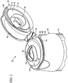
- FIG. 1 For ease of description, many of the figures illustrating the invention show a dispensing closure system in one preferred form of a separate dispensing closure in the typical orientation that the closure has when installed on the top of a container when the container is stored upright on its base, and terms such as upper, lower, horizontal, etc., are used with reference to this orientation. It will be understood, however, that the closure system of this invention may be manufactured, stored, transported, used, and sold in an orientation other than the orientation described.
- the dispensing closure system of this invention is suitable for use with a variety of conventional or special fluent substance dispensing systems, including packages, articles, and other dispensing equipment or apparatus, the details of which, although not fully illustrated or described, would be apparent to those having skill in the art and an understanding of such fluent substance dispensing systems.
- a fluent substance dispensing system, or portion thereof, with which the inventive dispensing closure system cooperates is hereinafter simply referred to as a "container.”
- the particular container, per se that is illustrated and described herein forms no part of, and therefore is not intended to limit, the broad aspects of the present invention. It will also be understood by those of ordinary skill that novel and non-obvious inventive aspects are embodied in the described exemplary dispensing closure system alone.
- a presently preferred embodiment of a dispensing closure system of the present invention is illustrated in the figures and is designated generally in many of those figures by reference number 20 (e.g., in FIG. 1 ).
- the closure system 20 is provided in the form of a separate dispensing closure 20 which is adapted to be mounted or installed on a container 22 (see, for example, FIGS. 1 and 3 ), and the container 22 would typically contain a product in the form of a fluent substance.
- the container 22 includes a neck 24 which extends upwardly from the hollow body portion of the container 22.
- the neck 24 defines a mouth on opening 26 to the container interior and product contained therein.
- the closure 20 is adapted to be threadingly, and removably, attached to the top of the container 22.
- the body of the container 22 may have any suitable configuration, and the upwardly projecting neck 24 may have a different cross-sectional size and/or shape than the container body. (Alternatively, the container 22 need not have a projecting neck 24, per se . Instead, the container 22 may have other configurations, such as a hollow body with an opening.)
- the dispensing closure system 20 of the present invention optionally may be provided as a unitary portion, or extension, of the top of the container 22.
- the dispensing closure system 20 is a completely separate article or unit (e.g., a dispensing closure 20) which can comprise either one piece or multiple pieces, and which is adapted to be removably, or non-removably, installed either on a previously manufactured container 22 that has an opening 26 to the container interior or that can be installed on a "container" portion of some other fluent substance handling system (e.g., machine, apparatus, etc.).
- the dispensing closure system or dispensing closure 20 will be more simply referred to as the "closure 20.”
- the illustrated, preferred embodiment of the closure 20 is adapted to be used with the container 22 having the opening 26 to provide access to the container interior and to a product (e.g., a material in the form of a fluent substance) contained therein.
- the closure 20 can be used to dispense various substances, including, but not limited to, liquids, suspensions, mixtures, etc. (such as, for example, fluent food products (e.g., a liquid dairy creamer or non-dairy creamer), a personal care product, an industrial or household cleaning product, or other compositions of matter (e.g., compositions for use in activities involving manufacturing, commercial or household maintenance, construction, agriculture, medical treatment, military operations, etc.)).
- fluent food products e.g., a liquid dairy creamer or non-dairy creamer
- a personal care product e.g., an industrial or household cleaning product
- compositions of matter e.g., compositions for use in activities involving manufacturing, commercial or household maintenance, construction, agriculture, medical
- the container 22 with which the closure 20 may be used may be a squeezable container having a flexible wall or walls which can be grasped by the user and squeezed or compressed to increase the internal pressure within the container so as to force the product out of the container and through the opened closure.
- a flexible container wall typically has sufficient, inherent resiliency so that when the squeezing forces are removed, the container wall returns to its normal, unstressed shape.
- Such a squeezable container is preferred in many applications but may not be necessary or preferred in other applications.
- the container can be substantially rigid, especially where the product is a low viscosity liquid that can be readily dispensed by inverting the container and then pouring the liquid through the opened closure.
- the preferred structure of the closure 20 comprises a body 30 (which may be characterized as defining a peripheral wall, base, or other analogous structure at the top of the container) and a lid 32 (i.e., top or cover) joined to the body 30 by a hinge 36.
- the closure body 30, lid 32, and hinge 36 are molded together as a unitary structure from a suitable thermoplastic material such as polypropylene or the like. Other materials may be employed instead.
- the closure 20 is initially molded as a completely separate article that is subsequently attached to the container 22 after the container 22 has been initially filled with a product.
- the closure body 30 includes an upper portion or deck 40. As can be seen in FIG. 3 , the body 30 has a lower portion 42 which extends downwardly from the periphery of the deck 40 and which includes an internal structure 44 for engaging the container neck 24 when the closure body 30 is mounted on the container 22. As can also be seen in FIG. 3 , the internal structure 44 of the closure body 30 defines an internal, female thread 46 for threadingly engaging the container neck external, male thread 28 when the dispensing closure body 30 is installed on the container neck 24.
- the closure body lower portion 42 could be provided with some other container connecting means, such as a snap-fit bead or groove (not illustrated) for engaging a container neck groove or bead (not illustrated), respectively.
- the closure body lower portion 42 could instead be permanently attached to the container 22 by means of induction melting, ultrasonic melting, gluing, or the like, depending on materials used for the closure body lower portion 42 and container 22.
- the closure body lower portion 42 could be formed (e.g., molded) as a unitary extension, or part, of the container 22.
- the closure body lower portion 42 may have any suitable configuration for accommodating an upwardly projecting neck 24 of the container 22 or for accommodating any other portion of a container received within the particular configuration of the closure body lower portion 42--even if a container does not have a neck, per se .
- the main part of the container 22 may have a different cross-sectional shape than the container neck 24 and closure body lower portion 42.
- the closure body lower portion 42 may be adapted for mounting to other types of fluent substance handling container systems (e.g., including dispensing apparatus, machines, or equipment).
- the container neck-receiving opening defined by the closure body internal structure 44 has a generally cylindrical configuration and includes the thread 46 that projects laterally inwardly.
- the closure body internal structure 44 may have other configurations.
- the closure body internal structure 44 might have a prism or polygon configuration adapted to be mounted to the top of a container neck having a polygon configuration.
- Such prism or polygon configurations might not accommodate a threaded attachment, but other means of attachment could be provided, such as a snap-fit bead and groove arrangement, adhesive, or the like.
- a type of "crab's claw” configuration seal 48 projects downwardly from the underside of the deck 40 to seal against the annular top surface of the container neck 24.
- Other conventional or special seal members could instead be provided to extend downwardly from the underside of the closure body deck 40.
- Such a seal member could be a conventional "V" seal, or some other such conventional or special seal, depending upon the particular application.
- the closure body 30 has an upwardly facing, exterior, peripheral shoulder 50 outwardly of the closure body deck 40, and also has a generally annular neck or wall 52 projecting upwardly from the inner edge of the shoulder 50.
- peripheral latch bead 54 located on the periphery of the wall 52 so as to project laterally outwardly from the wall 52 at an elevation above the shoulder 50.
- the latch bead 54 preferably does not extend all the way around the back of the closure body 30 in the region of the hinge 36.
- the closure body 30 has a spout 60 which projects upwardly from the deck 40 and which has a dispensing passage 62 defined at least in part by an interior surface 64 ( FIG. 4 ). At the bottom of the spout interior, a sealing bead 66 ( FIG. 4 ) projects laterally from the interior surface 64.
- the spout 60 is adapted to be covered by the lid 32.
- the lid 32 is provided to be closed over, and to cover, the upper part of the closure body 30.
- the lid 32 can be moved to expose the upper part of the closure body 30 to permit dispensing of the product from the container 22.
- the lid 32 is movable between (1) a closed position over the body 30 (as shown in FIGS. 1 and 3 ), and (2) an open position (as shown in FIGS. 2 and 4 ).
- the lid 32 is hinged to the closure body 30 by means of the hinge 36 so as to accommodate pivoting movement of the lid 32 between the closed position and the open position.
- the lid 32 includes a top end wall or cover 70 substantially surrounded by a peripheral flange 72.
- the closure hinge 36 is molded unitary with the lid flange 72 and with the closure body 30 so as to accommodate movement of the lid 32 between the open position exposing the closure spout dispensing passage 62, and the closed position occluding the closure spout dispensing passage 62.
- the hinge 36 may be of any suitable conventional or special design.
- the hinge 36 illustrated in the figures may be a conventional snap-action type such as described in the U.S. Patent No. 5,356,017 .
- the hinge could also be a non-snap-action type, including a strap or tether.
- the hinge could also be a conventional two-piece hinge, such as a clip hinge, in which an axle detail could be provided on the lid 32 and a socket to receive that axle could be provided on the closure body 30.
- the lid flange 72 has an end surface 74 for being received on, and abutting, the closure body shoulder 50 when the lid 32 is closed ( FIG. 3 ).
- the lower portion of the lid flange 72 may optionally include an inwardly projecting latch bead 76 ( FIG. 2 ).
- a finger tab or thumb tab 80 may optionally be provided to project laterally outwardly at the front of the closure lid 32.
- the upwardly facing surface of the lid latch bead 76 is below, and is adapted to engage, the downwardly facing surface of the overlying closure body latch bead 54.
- the closure body wall 52 and/or the lid flange 72 are sufficiently flexible to accommodate temporary, elastic, deformation as the beads 54 and 76 move past each other during the opening and closing actions.
- To open the lid 32 the user initially pushes with a thumb or finger upwardly on the bottom of the tab 80.
- Other conventional or special latch designs could be used instead. In some applications, there may be no need for a latch system at all (especially if the hinge 36 is of the "snap-action" type and has a very strong biasing force).
- the lid 32 includes a hollow spud 90 ( FIGS. 2 and 3 ) for entering into the dispensing passage 62 of the closure body spout 60 when the lid 32 is closed.
- the spud 90 extends from lid wall 70.
- the closure body spout 60 and the spud 90 each have configurations accommodating mating engagement when the lid 32 is closed, such as via sealing engagement of the spud 90 with the spout seal bead 66 (as seen in FIG. 4 ).
- the configuration of the spout 60 facilitates the pouring of fluent material from the spout 60 when the lid 32 is opened.
- the spud 90 can act to contain the movement of fluent materials within the inside of the spud 90 when the lid 32 is closed; thereby mitigating or avoiding undesired movement of fluent materials about the underside of the lid 32, and/or leakage of fluent materials between the closure body 30 and the lid 32.
- the spout 60 is configured to be narrower at its front side (i.e. the side furthest from the hinge 36) relative to other sides thereof, promoting the formation of a controlled stream of fluent material when the container 22 is tipped towards the front side of the closure 30 to pour fluent material through the dispensing passage 62.
- the spout 60 also includes a flared lip 61, which curves laterally outwards from the upper edge of the front side of the spout 60, further promoting the formation of a controlled stream of fluent material when poured through dispensing passage 62.
- the removable engagement of the lid spud 90 with the spout seal bead 66 is facilitated by the reduction in elevation of the spout 60 relative to the closure deck 40 at portions of the spout 60 nearest the hinge 36, thereby providing clearance for the pivoting insertion of the spud 90 into the dispensing passage 62.
- the container 22 When the lid 32 is in a closed position, the container 22 may be subjected to movement that causes materials within the container 22, such as liquids, to splash upwards, through the dispensing passage 62 and onto the interior surfaces of the spud 90.
- the container 22 may be utilized to contain mixtures, such as coffee creamer or other food products, whereby a consumer may desire to shake the container 22 prior to dispensing the contained product, in order to better mix the product.
- the container 22 may be subject to movement during transportation which results in splashing of contained product. In either case, droplets of such products may accumulate on the spud interior.
- the closure 22 in the illustrated embodiment includes features that may serve to reduce or eliminate the dripping of product accumulated on the interior of the spud 90, while the lid 32 is in an opened state.
- the spud 90 includes a spud rim 91. Rims such as the spud rim 91 are sometimes referred to as "drip catchers.”
- the spud rim 91 is formed at the distal end of the spud 90, and has a curved cross-section which extends laterally towards the interior of the spud 90.
- spud rims having non-curved cross-sectional configurations can also be employed.
- the spud rim 91 could be located at portions of the spud 90 other than the distal end, such as a position midway between the distal and proximal ends of the spud 90.
- the spud rim 91 extends along a portion of the periphery or circumference of the spud 90 that is nearest to the hinge 36, which is the direction in which the upper portion of container 22 will typically be tilted in order to dispense the contents of the container 22 from the spout 60.
- the spud rim 91 can serve to catch a droplet 100 of product or material that has accumulated on the interior of the spud 90, thereby preventing the droplet 100 from falling out onto the closure top deck 40 or into the surrounding environment.
- the spud rim 91 may provide other benefits in addition to controlling the movement of product accumulated on the interior of the spud 90.
- the spud rim 91 may serve to increase the rigidity of the walls of the spud 90.
- the curved outer surface of the spud rim 91 may promote the alignment of the spud 90 with the spout 60 during the process of closing the lid 32 onto the closure body 30.
- the present closure 22 features a second rim 33, which extends from the inside surface of lid top end wall 70.
- the illustrated embodiment of the second rim or lid rim 33 has a curved cross-section, although it is understood that non-curved cross-sections could also be employed.
- the length of the lid rim 33 is generally uniformly spaced from, or parallel to, a portion of the spud 90.
- the lid rim 33 extends outward from the interior surface of the lid top end wall 70 from a location proximate to a portion of the inside perimeter of the spud 90 that is oriented towards the hinge 36.
- the lid rim 33 curves inwardly toward the center portion of the hollow interior of the spud 90.
- the lid rim 33 serves to catch droplets of product or material that have accumulated on the interior of the spud 90, such as droplet 101 in FIG. 6 , thereby preventing droplet 101 from falling out onto the closure top deck 40 or into the surrounding environment.
- the positioning of the lid rim 33 relative to the top end wall 70 and/or the spud 90 may also act to improve the capacity of lid rim 33 to retain the fluent material by, for example, providing increased surface area and locations at which the fluent material can be retained.
- the lid rim 33 alone may be employed without any spud rim (e.g., rim 91). While the spud rim 91 may be beneficially employed embodiments employing both of the spud rim 91 and the lid rim 33 may be particularly effective in controlling or avoiding the undesired or uncontrolled dissemination of materials accumulating on the interior of the spud 90.
- spud rim 91 may be beneficially employed embodiments employing both of the spud rim 91 and the lid rim 33 may be particularly effective in controlling or avoiding the undesired or uncontrolled dissemination of materials accumulating on the interior of the spud 90.
- Embodiments of the invention such as the illustrated embodiment may be particularly advantageous, in that the facilities to manufacture the closure 22 can be readily tooled.
- the manufacture of the illustrated embedment of the closure 22 can be accomplished without the use of lifters or other complicated tool actions.
Abstract
Claims (13)
- Fermeture de distribution (20) pour un récipient (22) qui a une ouverture (26) par rapport à l'intérieur du récipient où une substance fluide peut être stockée, ladite ouverture de distribution (20) comprenant :(A) un corps (30) pour s'étendre à partir dudit récipient (22) au niveau de ladite ouverture de récipient (26), ledit corps (30) comprenant un bec verseur (60) qui a un passage de distribution (62) s'étendant à travers ledit bec verseur (60) ; et(B) un bouchon (32) pour le mouvement entre (1) une position fermée bouchant ledit passage de distribution (62) du bec verseur, et (2) une position ouverte exposant ledit passage de distribution (62) du bec verseur, ledit bouchon (32) ayant un ergot (90) pour entrer dans ledit passage de distribution (62) du bec verseur lorsque ledit bouchon (32) est dans ladite position fermée, ledit ergot (90) ayant un intérieur creux, ledit bouchon (32) ayant en outre un rebord (33) à proximité dudit ergot (90) s'étendant latéralement vers et exposé à l'intérieur creux,caractérisée en ce que ledit rebord (33) est un rebord de bouchon positionné à l'intérieur dudit intérieur creux dudit ergot (90), s'étendant latéralement vers le centre dudit intérieur creux dudit ergot (90).
- Fermeture de distribution (20) selon la revendication 1, dans laquelle ladite fermeture (20) est adaptée pour se fixer à un récipient (22) qui a une ouverture de récipient (26) par rapport audit intérieur de récipient ; ladite fermeture (20) est initialement séparée de, mais pouvant être fixée de manière amovible ou non amovible audit récipient (22) autour de ladite ouverture de récipient (26) ; et ledit passage de distribution (62) du bec verseur du corps de fermeture communique avec ladite ouverture de récipient (26) lorsque ledit corps de fermeture (30) est fixé audit récipient (22).
- Fermeture de distribution (20) selon la revendication 1, dans laquelle ledit ergot (90) met en prise de manière étanche une surface interne (64) dudit passage de distribution (62) du bec verseur.
- Fermeture de distribution (20) selon la revendication 3, dans laquelle ladite surface interne (64) dudit passage de distribution (62) du bec verseur comprend un bourrelet d'étanchéité (66), contre lequel ledit ergot (90) se met en prise de manière étanche.
- Fermeture de distribution (20) selon la revendication 1, comprenant en outre un rebord d'ergot (91) unitaire avec ledit ergot et s'étendant latéralement à partir dudit ergot (90).
- Fermeture de distribution (20) selon la revendication 5, dans laquelle ledit ergot (90) a une extrémité distale, et ledit rebord d'ergot (91) est formé au niveau de l'extrémité distale dudit ergot (90).
- Fermeture de distribution (20) selon la revendication 5, dans laquelle ledit rebord d'ergot (91) s'incurve latéralement vers ledit intérieur creux.
- Fermeture de distribution (20) selon la revendication 5, dans laquelle ledit bouchon (32) est fixé audit corps (30) via une charnière (36) ; et ledit rebord d'ergot (91) est positionné le long d'une partie dudit ergot (90) qui est à proximité de ladite charnière (36).
- Fermeture de distribution (20) selon la revendication 1, dans laquelle ledit rebord de bouchon (33) s'incurve latéralement vers le centre dudit intérieur creux dudit ergot (90).
- Fermeture de distribution (20) selon la revendication 1, dans laquelle ledit bouchon (32) a une extrémité supérieure (70) définissant une surface interne ; et ledit rebord de bouchon (33) fait saillie de ladite surface interne dudit bouchon (32).
- Fermeture de distribution (20) selon la revendication 10, dans laquelle ledit rebord de bouchon (33) est à proximité de et uniformément espacé d'une partie de la surface interne dudit ergot (90).
- Fermeture de distribution (20) selon la revendication 10, dans laquelle ledit bouchon (32) est fixé audit corps (30) via une charnière (36) ; et ledit rebord de bouchon (33) est à proximité de et uniformément espacé d'une partie de la surface interne dudit ergot (90) qui est orientée vers ladite charnière (36).
- Fermeture de distribution (20) selon la revendication 1, dans laquelle ledit rebord de bouchon (33) s'incurve latéralement vers le centre dudit intérieur creux dudit ergot (90) ; ledit bouchon (32) a une extrémité supérieure (70) définissant une surface interne ; ledit rebord de bouchon (33) fait saillie de ladite surface interne dudit bouchon (32) ; ledit bouchon (32) est fixé audit corps (30) via une charnière (36) ; et ledit rebord de bouchon (33) est à proximité de et uniformément espacé d'une partie de la surface interne dudit ergot (90) qui est orientée vers ladite charnière (36).
Priority Applications (1)
| Application Number | Priority Date | Filing Date | Title |
|---|---|---|---|
| PL09726357T PL2254804T3 (pl) | 2008-03-27 | 2009-03-09 | Zamknięcie z wieczkiem zmniejszającym przeciekanie |
Applications Claiming Priority (2)
| Application Number | Priority Date | Filing Date | Title |
|---|---|---|---|
| US12/079,533 US8267274B2 (en) | 2008-03-27 | 2008-03-27 | Closure having a drip minimizing lid |
| PCT/US2009/001492 WO2009120261A2 (fr) | 2008-03-27 | 2009-03-09 | Fermeture ayant un bouchon destiné à minimaliser la formation de gouttes |
Publications (3)
| Publication Number | Publication Date |
|---|---|
| EP2254804A2 EP2254804A2 (fr) | 2010-12-01 |
| EP2254804A4 EP2254804A4 (fr) | 2011-03-23 |
| EP2254804B1 true EP2254804B1 (fr) | 2012-05-16 |
Family
ID=41114497
Family Applications (1)
| Application Number | Title | Priority Date | Filing Date |
|---|---|---|---|
| EP09726357A Active EP2254804B1 (fr) | 2008-03-27 | 2009-03-09 | Fermeture ayant un bouchon destiné à minimaliser la formation de gouttes |
Country Status (10)
| Country | Link |
|---|---|
| US (2) | US8267274B2 (fr) |
| EP (1) | EP2254804B1 (fr) |
| CN (1) | CN101980926B (fr) |
| AR (1) | AR071103A1 (fr) |
| BR (1) | BRPI0909387B1 (fr) |
| ES (1) | ES2384494T3 (fr) |
| MX (1) | MX2010008944A (fr) |
| PL (1) | PL2254804T3 (fr) |
| RU (1) | RU2493075C2 (fr) |
| WO (1) | WO2009120261A2 (fr) |
Families Citing this family (26)
| Publication number | Priority date | Publication date | Assignee | Title |
|---|---|---|---|---|
| US8267274B2 (en) * | 2008-03-27 | 2012-09-18 | Aptargroup, Inc. | Closure having a drip minimizing lid |
| GB201017913D0 (en) * | 2010-10-22 | 2010-12-01 | Obrist Closures Switzerland | a closure |
| BR112013025927B1 (pt) * | 2011-04-08 | 2020-03-31 | Aptar Freyung Gmbh | Fechamento para um recipiente, recipiente e unidade de recipiente |
| PL2844610T3 (pl) * | 2012-05-02 | 2018-12-31 | Aptargroup, Inc. | Zamknięcie pojemnika do odpowietrzonego wylewania przez wydłużony otwór |
| JP5885593B2 (ja) * | 2012-05-31 | 2016-03-15 | 株式会社吉野工業所 | 液回収リブ付きヒンジキャップ |
| US9102444B2 (en) | 2012-10-26 | 2015-08-11 | Enterprise Express, Inc. | Beverage container lid |
| MX2016013284A (es) * | 2014-05-28 | 2017-01-18 | Aptargroup Inc | Accesorio para un recipiente flexible. |
| WO2016043745A1 (fr) * | 2014-09-18 | 2016-03-24 | Colgate-Palmolive Company | Capuchon à rabat |
| US11064711B2 (en) | 2015-08-27 | 2021-07-20 | Societe Des Produits Nestle S.A. | Closures for liquid-dispensing containers and methods for making and using such closures |
| CN108473237B (zh) * | 2015-12-23 | 2019-12-10 | 荷兰联合利华有限公司 | 封闭件 |
| WO2017192861A1 (fr) * | 2016-05-05 | 2017-11-09 | Berry Plastics Corporation | Bouchon |
| USD871904S1 (en) | 2017-01-05 | 2020-01-07 | Silgan White Cap LLC | Closure |
| US10966690B2 (en) * | 2017-03-28 | 2021-04-06 | Marc Kopoian | Specimen container system |
| WO2019177616A1 (fr) * | 2018-03-15 | 2019-09-19 | Bericap Inc. | Fermeture de récipient à attache |
| EP3823458A4 (fr) | 2018-11-05 | 2021-12-15 | AptarGroup, Inc. | Fermeture pour récipient ayant des caractéristiques de retenue améliorées |
| US11510512B2 (en) | 2019-09-20 | 2022-11-29 | Leapfrog Product Development LLC | Soft straw lid for beverage container |
| US11628983B2 (en) * | 2019-09-20 | 2023-04-18 | Leapfrog Product Development LLC | Soft chug lid for beverage container |
| US10843849B1 (en) * | 2019-10-01 | 2020-11-24 | Silgan White Cap LLC | Flip top dispensing closure |
| WO2021206899A1 (fr) * | 2020-04-08 | 2021-10-14 | Intercontinental Great Brands Llc | Couvercle refermable pour récipient |
| USD957196S1 (en) | 2020-10-27 | 2022-07-12 | Yeti Coolers, Llc | Bottle |
| US20230055070A1 (en) * | 2021-08-19 | 2023-02-23 | Closure Systems International Inc. | One-piece closure |
| USD1015804S1 (en) | 2021-09-15 | 2024-02-27 | Yeti Coolers, Llc | Lid |
| USD1012705S1 (en) * | 2021-09-20 | 2024-01-30 | Closure Systems International Inc. | Closure |
| WO2023069387A1 (fr) * | 2021-10-21 | 2023-04-27 | Aptargroup, Inc. | Bouchon distributeur |
| USD998463S1 (en) * | 2021-10-29 | 2023-09-12 | Closure Systems International Inc. | Closure |
| US20230249882A1 (en) * | 2022-02-08 | 2023-08-10 | Michael Angelo Gomez | Bottle cap with a flip lid |
Family Cites Families (14)
| Publication number | Priority date | Publication date | Assignee | Title |
|---|---|---|---|---|
| CH619413A5 (en) | 1977-07-22 | 1980-09-30 | Createchnic Patent Ag | Plastic closure for fixed and deformable containers |
| US4387819A (en) * | 1981-12-23 | 1983-06-14 | Corsette Douglas Frank | Sealing means for a snap-on fitment |
| DE8325565U1 (de) | 1983-09-06 | 1984-08-16 | Heinrich Josef Winter Kunststoffverarbeitung Und Werkzeugbau Gmbh, 6452 Hainburg | Schraubkappe aus Kunststoff |
| US4566603A (en) * | 1984-07-12 | 1986-01-28 | Phoenix Closures, Inc. | Linerless closure |
| US5143234A (en) * | 1991-08-12 | 1992-09-01 | Zeller Closures, Inc. | Single walled dispensing closures with positive alignment means |
| US5794299A (en) * | 1996-08-29 | 1998-08-18 | Ontrak Systems, Inc. | Containment apparatus |
| ID22675A (id) * | 1998-03-03 | 1999-12-09 | Heinz Frank Schellenbach | Penutup plastik yang terdiri dari cincin pengaman yang dapat dilepaskan dan segel bagian dalam |
| US6367670B1 (en) * | 2000-04-05 | 2002-04-09 | Nestec S.A. | Container cap having integral pour spout |
| BR0111425A (pt) * | 2000-06-09 | 2003-12-23 | Seaquist Closures | Fechamento de distribuição para produto dispersavel |
| AU2001291618A1 (en) | 2000-08-30 | 2002-03-13 | Weiss Kg | Screw-type cap consisting of plastic |
| US6405885B1 (en) * | 2000-12-22 | 2002-06-18 | Seaquist Closures Foreign, Inc. | Locking tamper-evident dispensing closure |
| US6880736B1 (en) * | 2002-09-23 | 2005-04-19 | Owens-Illinois Closure Inc. | Dispensing closure, package and method of manufacture |
| US20090101646A1 (en) * | 2007-10-23 | 2009-04-23 | Whitewave Services, Inc. | Storage and Dispensing System |
| US8267274B2 (en) * | 2008-03-27 | 2012-09-18 | Aptargroup, Inc. | Closure having a drip minimizing lid |
-
2008
- 2008-03-27 US US12/079,533 patent/US8267274B2/en active Active
-
2009
- 2009-03-09 RU RU2010143904/12A patent/RU2493075C2/ru not_active IP Right Cessation
- 2009-03-09 CN CN2009801119284A patent/CN101980926B/zh active Active
- 2009-03-09 MX MX2010008944A patent/MX2010008944A/es active IP Right Grant
- 2009-03-09 EP EP09726357A patent/EP2254804B1/fr active Active
- 2009-03-09 PL PL09726357T patent/PL2254804T3/pl unknown
- 2009-03-09 ES ES09726357T patent/ES2384494T3/es active Active
- 2009-03-09 WO PCT/US2009/001492 patent/WO2009120261A2/fr active Application Filing
- 2009-03-09 BR BRPI0909387A patent/BRPI0909387B1/pt active IP Right Grant
- 2009-03-27 AR ARP090101112A patent/AR071103A1/es not_active Application Discontinuation
-
2012
- 2012-06-12 US US13/494,119 patent/US8474646B2/en active Active
Also Published As
| Publication number | Publication date |
|---|---|
| PL2254804T3 (pl) | 2012-10-31 |
| US8474646B2 (en) | 2013-07-02 |
| RU2010143904A (ru) | 2012-05-10 |
| US20090242564A1 (en) | 2009-10-01 |
| EP2254804A2 (fr) | 2010-12-01 |
| MX2010008944A (es) | 2010-09-10 |
| WO2009120261A3 (fr) | 2009-12-30 |
| BRPI0909387B1 (pt) | 2019-01-22 |
| RU2493075C2 (ru) | 2013-09-20 |
| AR071103A1 (es) | 2010-05-26 |
| CN101980926B (zh) | 2012-07-11 |
| BRPI0909387A2 (pt) | 2015-10-06 |
| EP2254804A4 (fr) | 2011-03-23 |
| ES2384494T3 (es) | 2012-07-05 |
| WO2009120261A2 (fr) | 2009-10-01 |
| US8267274B2 (en) | 2012-09-18 |
| CN101980926A (zh) | 2011-02-23 |
| US20120248133A1 (en) | 2012-10-04 |
Similar Documents
| Publication | Publication Date | Title |
|---|---|---|
| EP2254804B1 (fr) | Fermeture ayant un bouchon destiné à minimaliser la formation de gouttes | |
| CA2866048C (fr) | Capuchon de recipient pour verser avec entree d'air un contenu a travers une ouverture allongee | |
| US7530478B2 (en) | Closure with one or more lids | |
| AU737612B2 (en) | Dispensing structure with frangible membrane for separating two products | |
| US8141731B2 (en) | Closure with lid and slidable latch system | |
| US9073673B2 (en) | Closure for an inverted container | |
| US4782985A (en) | Closure for drip and pour dispensing | |
| US5850953A (en) | Drip-free dispensing structure with collecting reservoir | |
| US6419101B1 (en) | Tear band closure | |
| US8960506B2 (en) | Closure accommodating pouring from an inverted container | |
| US20150090743A1 (en) | Container Closure For Vented Pouring Through A Curved Aperture | |
| US4047648A (en) | Spout with snap acting cover and drain hole | |
| US20170050780A1 (en) | Closure with membrane | |
| US20100294812A1 (en) | Internal container bore mount fitment | |
| US9315304B2 (en) | Closure with sliding seal member | |
| WO2011146438A1 (fr) | Bouchon de récipient | |
| NL2032534B1 (en) | A spouted container and closure assembly. | |
| ZA200903074B (en) | Accessory for a container |
Legal Events
| Date | Code | Title | Description |
|---|---|---|---|
| PUAI | Public reference made under article 153(3) epc to a published international application that has entered the european phase |
Free format text: ORIGINAL CODE: 0009012 |
|
| 17P | Request for examination filed |
Effective date: 20100811 |
|
| AK | Designated contracting states |
Kind code of ref document: A2 Designated state(s): AT BE BG CH CY CZ DE DK EE ES FI FR GB GR HR HU IE IS IT LI LT LU LV MC MK MT NL NO PL PT RO SE SI SK TR |
|
| AX | Request for extension of the european patent |
Extension state: AL BA RS |
|
| A4 | Supplementary search report drawn up and despatched |
Effective date: 20110218 |
|
| DAX | Request for extension of the european patent (deleted) | ||
| RIC1 | Information provided on ipc code assigned before grant |
Ipc: B65D 43/14 20060101AFI20110711BHEP |
|
| GRAP | Despatch of communication of intention to grant a patent |
Free format text: ORIGINAL CODE: EPIDOSNIGR1 |
|
| GRAS | Grant fee paid |
Free format text: ORIGINAL CODE: EPIDOSNIGR3 |
|
| RAP1 | Party data changed (applicant data changed or rights of an application transferred) |
Owner name: APTARGROUP, INC. |
|
| GRAA | (expected) grant |
Free format text: ORIGINAL CODE: 0009210 |
|
| AK | Designated contracting states |
Kind code of ref document: B1 Designated state(s): AT BE BG CH CY CZ DE DK EE ES FI FR GB GR HR HU IE IS IT LI LT LU LV MC MK MT NL NO PL PT RO SE SI SK TR |
|
| REG | Reference to a national code |
Ref country code: GB Ref legal event code: FG4D |
|
| REG | Reference to a national code |
Ref country code: CH Ref legal event code: EP |
|
| REG | Reference to a national code |
Ref country code: AT Ref legal event code: REF Ref document number: 557987 Country of ref document: AT Kind code of ref document: T Effective date: 20120615 |
|
| REG | Reference to a national code |
Ref country code: IE Ref legal event code: FG4D |
|
| REG | Reference to a national code |
Ref country code: ES Ref legal event code: FG2A Ref document number: 2384494 Country of ref document: ES Kind code of ref document: T3 Effective date: 20120705 |
|
| REG | Reference to a national code |
Ref country code: DE Ref legal event code: R096 Ref document number: 602009007063 Country of ref document: DE Effective date: 20120712 |
|
| REG | Reference to a national code |
Ref country code: NL Ref legal event code: VDEP Effective date: 20120516 |
|
| REG | Reference to a national code |
Ref country code: LT Ref legal event code: MG4D Effective date: 20120516 |
|
| PG25 | Lapsed in a contracting state [announced via postgrant information from national office to epo] |
Ref country code: IS Free format text: LAPSE BECAUSE OF FAILURE TO SUBMIT A TRANSLATION OF THE DESCRIPTION OR TO PAY THE FEE WITHIN THE PRESCRIBED TIME-LIMIT Effective date: 20120916 Ref country code: FI Free format text: LAPSE BECAUSE OF FAILURE TO SUBMIT A TRANSLATION OF THE DESCRIPTION OR TO PAY THE FEE WITHIN THE PRESCRIBED TIME-LIMIT Effective date: 20120516 Ref country code: CY Free format text: LAPSE BECAUSE OF FAILURE TO SUBMIT A TRANSLATION OF THE DESCRIPTION OR TO PAY THE FEE WITHIN THE PRESCRIBED TIME-LIMIT Effective date: 20120516 Ref country code: SE Free format text: LAPSE BECAUSE OF FAILURE TO SUBMIT A TRANSLATION OF THE DESCRIPTION OR TO PAY THE FEE WITHIN THE PRESCRIBED TIME-LIMIT Effective date: 20120516 Ref country code: LT Free format text: LAPSE BECAUSE OF FAILURE TO SUBMIT A TRANSLATION OF THE DESCRIPTION OR TO PAY THE FEE WITHIN THE PRESCRIBED TIME-LIMIT Effective date: 20120516 Ref country code: NO Free format text: LAPSE BECAUSE OF FAILURE TO SUBMIT A TRANSLATION OF THE DESCRIPTION OR TO PAY THE FEE WITHIN THE PRESCRIBED TIME-LIMIT Effective date: 20120816 |
|
| REG | Reference to a national code |
Ref country code: PL Ref legal event code: T3 |
|
| REG | Reference to a national code |
Ref country code: AT Ref legal event code: MK05 Ref document number: 557987 Country of ref document: AT Kind code of ref document: T Effective date: 20120516 |
|
| PG25 | Lapsed in a contracting state [announced via postgrant information from national office to epo] |
Ref country code: GR Free format text: LAPSE BECAUSE OF FAILURE TO SUBMIT A TRANSLATION OF THE DESCRIPTION OR TO PAY THE FEE WITHIN THE PRESCRIBED TIME-LIMIT Effective date: 20120817 Ref country code: SI Free format text: LAPSE BECAUSE OF FAILURE TO SUBMIT A TRANSLATION OF THE DESCRIPTION OR TO PAY THE FEE WITHIN THE PRESCRIBED TIME-LIMIT Effective date: 20120516 Ref country code: HR Free format text: LAPSE BECAUSE OF FAILURE TO SUBMIT A TRANSLATION OF THE DESCRIPTION OR TO PAY THE FEE WITHIN THE PRESCRIBED TIME-LIMIT Effective date: 20120516 Ref country code: PT Free format text: LAPSE BECAUSE OF FAILURE TO SUBMIT A TRANSLATION OF THE DESCRIPTION OR TO PAY THE FEE WITHIN THE PRESCRIBED TIME-LIMIT Effective date: 20120917 Ref country code: LV Free format text: LAPSE BECAUSE OF FAILURE TO SUBMIT A TRANSLATION OF THE DESCRIPTION OR TO PAY THE FEE WITHIN THE PRESCRIBED TIME-LIMIT Effective date: 20120516 |
|
| PG25 | Lapsed in a contracting state [announced via postgrant information from national office to epo] |
Ref country code: BE Free format text: LAPSE BECAUSE OF FAILURE TO SUBMIT A TRANSLATION OF THE DESCRIPTION OR TO PAY THE FEE WITHIN THE PRESCRIBED TIME-LIMIT Effective date: 20120516 |
|
| PG25 | Lapsed in a contracting state [announced via postgrant information from national office to epo] |
Ref country code: AT Free format text: LAPSE BECAUSE OF FAILURE TO SUBMIT A TRANSLATION OF THE DESCRIPTION OR TO PAY THE FEE WITHIN THE PRESCRIBED TIME-LIMIT Effective date: 20120516 Ref country code: EE Free format text: LAPSE BECAUSE OF FAILURE TO SUBMIT A TRANSLATION OF THE DESCRIPTION OR TO PAY THE FEE WITHIN THE PRESCRIBED TIME-LIMIT Effective date: 20120516 Ref country code: RO Free format text: LAPSE BECAUSE OF FAILURE TO SUBMIT A TRANSLATION OF THE DESCRIPTION OR TO PAY THE FEE WITHIN THE PRESCRIBED TIME-LIMIT Effective date: 20120516 Ref country code: DK Free format text: LAPSE BECAUSE OF FAILURE TO SUBMIT A TRANSLATION OF THE DESCRIPTION OR TO PAY THE FEE WITHIN THE PRESCRIBED TIME-LIMIT Effective date: 20120516 Ref country code: SK Free format text: LAPSE BECAUSE OF FAILURE TO SUBMIT A TRANSLATION OF THE DESCRIPTION OR TO PAY THE FEE WITHIN THE PRESCRIBED TIME-LIMIT Effective date: 20120516 Ref country code: NL Free format text: LAPSE BECAUSE OF FAILURE TO SUBMIT A TRANSLATION OF THE DESCRIPTION OR TO PAY THE FEE WITHIN THE PRESCRIBED TIME-LIMIT Effective date: 20120516 |
|
| PLBE | No opposition filed within time limit |
Free format text: ORIGINAL CODE: 0009261 |
|
| STAA | Information on the status of an ep patent application or granted ep patent |
Free format text: STATUS: NO OPPOSITION FILED WITHIN TIME LIMIT |
|
| 26N | No opposition filed |
Effective date: 20130219 |
|
| REG | Reference to a national code |
Ref country code: DE Ref legal event code: R097 Ref document number: 602009007063 Country of ref document: DE Effective date: 20130219 |
|
| PG25 | Lapsed in a contracting state [announced via postgrant information from national office to epo] |
Ref country code: BG Free format text: LAPSE BECAUSE OF FAILURE TO SUBMIT A TRANSLATION OF THE DESCRIPTION OR TO PAY THE FEE WITHIN THE PRESCRIBED TIME-LIMIT Effective date: 20120816 |
|
| PG25 | Lapsed in a contracting state [announced via postgrant information from national office to epo] |
Ref country code: MC Free format text: LAPSE BECAUSE OF NON-PAYMENT OF DUE FEES Effective date: 20130331 |
|
| REG | Reference to a national code |
Ref country code: CH Ref legal event code: PL |
|
| REG | Reference to a national code |
Ref country code: IE Ref legal event code: MM4A |
|
| PG25 | Lapsed in a contracting state [announced via postgrant information from national office to epo] |
Ref country code: LI Free format text: LAPSE BECAUSE OF NON-PAYMENT OF DUE FEES Effective date: 20130331 Ref country code: IE Free format text: LAPSE BECAUSE OF NON-PAYMENT OF DUE FEES Effective date: 20130309 Ref country code: CH Free format text: LAPSE BECAUSE OF NON-PAYMENT OF DUE FEES Effective date: 20130331 |
|
| PG25 | Lapsed in a contracting state [announced via postgrant information from national office to epo] |
Ref country code: MT Free format text: LAPSE BECAUSE OF FAILURE TO SUBMIT A TRANSLATION OF THE DESCRIPTION OR TO PAY THE FEE WITHIN THE PRESCRIBED TIME-LIMIT Effective date: 20120516 |
|
| PGFP | Annual fee paid to national office [announced via postgrant information from national office to epo] |
Ref country code: CZ Payment date: 20150227 Year of fee payment: 7 |
|
| PGFP | Annual fee paid to national office [announced via postgrant information from national office to epo] |
Ref country code: PL Payment date: 20150223 Year of fee payment: 7 |
|
| PG25 | Lapsed in a contracting state [announced via postgrant information from national office to epo] |
Ref country code: TR Free format text: LAPSE BECAUSE OF FAILURE TO SUBMIT A TRANSLATION OF THE DESCRIPTION OR TO PAY THE FEE WITHIN THE PRESCRIBED TIME-LIMIT Effective date: 20120516 |
|
| PG25 | Lapsed in a contracting state [announced via postgrant information from national office to epo] |
Ref country code: LU Free format text: LAPSE BECAUSE OF NON-PAYMENT OF DUE FEES Effective date: 20130309 Ref country code: HU Free format text: LAPSE BECAUSE OF FAILURE TO SUBMIT A TRANSLATION OF THE DESCRIPTION OR TO PAY THE FEE WITHIN THE PRESCRIBED TIME-LIMIT; INVALID AB INITIO Effective date: 20090309 Ref country code: MK Free format text: LAPSE BECAUSE OF FAILURE TO SUBMIT A TRANSLATION OF THE DESCRIPTION OR TO PAY THE FEE WITHIN THE PRESCRIBED TIME-LIMIT Effective date: 20120516 |
|
| REG | Reference to a national code |
Ref country code: FR Ref legal event code: PLFP Year of fee payment: 8 |
|
| PG25 | Lapsed in a contracting state [announced via postgrant information from national office to epo] |
Ref country code: CZ Free format text: LAPSE BECAUSE OF NON-PAYMENT OF DUE FEES Effective date: 20160309 |
|
| REG | Reference to a national code |
Ref country code: FR Ref legal event code: PLFP Year of fee payment: 9 |
|
| PG25 | Lapsed in a contracting state [announced via postgrant information from national office to epo] |
Ref country code: PL Free format text: LAPSE BECAUSE OF NON-PAYMENT OF DUE FEES Effective date: 20160309 |
|
| REG | Reference to a national code |
Ref country code: FR Ref legal event code: PLFP Year of fee payment: 10 |
|
| PGFP | Annual fee paid to national office [announced via postgrant information from national office to epo] |
Ref country code: FR Payment date: 20230327 Year of fee payment: 15 |
|
| PGFP | Annual fee paid to national office [announced via postgrant information from national office to epo] |
Ref country code: IT Payment date: 20230321 Year of fee payment: 15 |
|
| P01 | Opt-out of the competence of the unified patent court (upc) registered |
Effective date: 20230509 |
|
| PGFP | Annual fee paid to national office [announced via postgrant information from national office to epo] |
Ref country code: ES Payment date: 20230403 Year of fee payment: 15 |
|
| PGFP | Annual fee paid to national office [announced via postgrant information from national office to epo] |
Ref country code: DE Payment date: 20240327 Year of fee payment: 16 Ref country code: GB Payment date: 20240327 Year of fee payment: 16 |