EP2254494B1 - System zur einführung eines flexiblen wirbelsäulen-stabilisationselements - Google Patents
System zur einführung eines flexiblen wirbelsäulen-stabilisationselements Download PDFInfo
- Publication number
- EP2254494B1 EP2254494B1 EP08872028A EP08872028A EP2254494B1 EP 2254494 B1 EP2254494 B1 EP 2254494B1 EP 08872028 A EP08872028 A EP 08872028A EP 08872028 A EP08872028 A EP 08872028A EP 2254494 B1 EP2254494 B1 EP 2254494B1
- Authority
- EP
- European Patent Office
- Prior art keywords
- connecting element
- delivery device
- vertebral
- patient
- positioning tool
- Prior art date
- Legal status (The legal status is an assumption and is not a legal conclusion. Google has not performed a legal analysis and makes no representation as to the accuracy of the status listed.)
- Not-in-force
Links
- 230000006641 stabilisation Effects 0.000 title claims abstract description 47
- 238000011105 stabilization Methods 0.000 title claims abstract description 47
- 238000003780 insertion Methods 0.000 title description 14
- 230000037431 insertion Effects 0.000 title description 14
- 125000006850 spacer group Chemical group 0.000 claims description 48
- -1 polyethylene Polymers 0.000 claims description 3
- 239000004698 Polyethylene Substances 0.000 claims description 2
- 229920000573 polyethylene Polymers 0.000 claims description 2
- 238000000034 method Methods 0.000 abstract description 74
- 230000008878 coupling Effects 0.000 abstract description 6
- 238000010168 coupling process Methods 0.000 abstract description 6
- 238000005859 coupling reaction Methods 0.000 abstract description 6
- 239000000463 material Substances 0.000 description 17
- 210000001519 tissue Anatomy 0.000 description 10
- 239000007943 implant Substances 0.000 description 7
- 230000000087 stabilizing effect Effects 0.000 description 7
- 230000000717 retained effect Effects 0.000 description 4
- 238000001356 surgical procedure Methods 0.000 description 4
- 230000004927 fusion Effects 0.000 description 3
- 238000010276 construction Methods 0.000 description 2
- 230000000694 effects Effects 0.000 description 2
- 238000009434 installation Methods 0.000 description 2
- 230000013011 mating Effects 0.000 description 2
- 239000002184 metal Substances 0.000 description 2
- 229910052751 metal Inorganic materials 0.000 description 2
- 238000002355 open surgical procedure Methods 0.000 description 2
- 229920001692 polycarbonate urethane Polymers 0.000 description 2
- 229920000139 polyethylene terephthalate Polymers 0.000 description 2
- 239000005020 polyethylene terephthalate Substances 0.000 description 2
- 239000012781 shape memory material Substances 0.000 description 2
- 239000004696 Poly ether ether ketone Substances 0.000 description 1
- 208000020307 Spinal disease Diseases 0.000 description 1
- RTAQQCXQSZGOHL-UHFFFAOYSA-N Titanium Chemical compound [Ti] RTAQQCXQSZGOHL-UHFFFAOYSA-N 0.000 description 1
- 230000002159 abnormal effect Effects 0.000 description 1
- 230000002411 adverse Effects 0.000 description 1
- 238000013459 approach Methods 0.000 description 1
- JUPQTSLXMOCDHR-UHFFFAOYSA-N benzene-1,4-diol;bis(4-fluorophenyl)methanone Chemical compound OC1=CC=C(O)C=C1.C1=CC(F)=CC=C1C(=O)C1=CC=C(F)C=C1 JUPQTSLXMOCDHR-UHFFFAOYSA-N 0.000 description 1
- 230000036760 body temperature Effects 0.000 description 1
- 210000000988 bone and bone Anatomy 0.000 description 1
- 239000002639 bone cement Substances 0.000 description 1
- 230000008859 change Effects 0.000 description 1
- 230000006835 compression Effects 0.000 description 1
- 238000007906 compression Methods 0.000 description 1
- 238000007796 conventional method Methods 0.000 description 1
- 230000001419 dependent effect Effects 0.000 description 1
- 239000013013 elastic material Substances 0.000 description 1
- 239000000945 filler Substances 0.000 description 1
- 239000003550 marker Substances 0.000 description 1
- 238000005259 measurement Methods 0.000 description 1
- 230000007246 mechanism Effects 0.000 description 1
- 239000007769 metal material Substances 0.000 description 1
- 238000012986 modification Methods 0.000 description 1
- 230000004048 modification Effects 0.000 description 1
- 210000003205 muscle Anatomy 0.000 description 1
- HLXZNVUGXRDIFK-UHFFFAOYSA-N nickel titanium Chemical compound [Ti].[Ti].[Ti].[Ti].[Ti].[Ti].[Ti].[Ti].[Ti].[Ti].[Ti].[Ni].[Ni].[Ni].[Ni].[Ni].[Ni].[Ni].[Ni].[Ni].[Ni].[Ni].[Ni].[Ni].[Ni] HLXZNVUGXRDIFK-UHFFFAOYSA-N 0.000 description 1
- 229910001000 nickel titanium Inorganic materials 0.000 description 1
- 229920002530 polyetherether ketone Polymers 0.000 description 1
- 230000008569 process Effects 0.000 description 1
- 238000011084 recovery Methods 0.000 description 1
- 230000008439 repair process Effects 0.000 description 1
- 238000004513 sizing Methods 0.000 description 1
- 239000007787 solid Substances 0.000 description 1
- 239000010936 titanium Substances 0.000 description 1
- 229910052719 titanium Inorganic materials 0.000 description 1
- 239000011800 void material Substances 0.000 description 1
Images


Classifications
-
- A—HUMAN NECESSITIES
- A61—MEDICAL OR VETERINARY SCIENCE; HYGIENE
- A61B—DIAGNOSIS; SURGERY; IDENTIFICATION
- A61B17/00—Surgical instruments, devices or methods
- A61B17/56—Surgical instruments or methods for treatment of bones or joints; Devices specially adapted therefor
- A61B17/58—Surgical instruments or methods for treatment of bones or joints; Devices specially adapted therefor for osteosynthesis, e.g. bone plates, screws or setting implements
- A61B17/68—Internal fixation devices, including fasteners and spinal fixators, even if a part thereof projects from the skin
- A61B17/70—Spinal positioners or stabilisers, e.g. stabilisers comprising fluid filler in an implant
- A61B17/7001—Screws or hooks combined with longitudinal elements which do not contact vertebrae
- A61B17/7002—Longitudinal elements, e.g. rods
- A61B17/7019—Longitudinal elements having flexible parts, or parts connected together, such that after implantation the elements can move relative to each other
- A61B17/7031—Longitudinal elements having flexible parts, or parts connected together, such that after implantation the elements can move relative to each other made wholly or partly of flexible material
-
- A—HUMAN NECESSITIES
- A61—MEDICAL OR VETERINARY SCIENCE; HYGIENE
- A61B—DIAGNOSIS; SURGERY; IDENTIFICATION
- A61B17/00—Surgical instruments, devices or methods
- A61B17/56—Surgical instruments or methods for treatment of bones or joints; Devices specially adapted therefor
- A61B17/58—Surgical instruments or methods for treatment of bones or joints; Devices specially adapted therefor for osteosynthesis, e.g. bone plates, screws or setting implements
- A61B17/68—Internal fixation devices, including fasteners and spinal fixators, even if a part thereof projects from the skin
- A61B17/70—Spinal positioners or stabilisers, e.g. stabilisers comprising fluid filler in an implant
- A61B17/7001—Screws or hooks combined with longitudinal elements which do not contact vertebrae
- A61B17/7002—Longitudinal elements, e.g. rods
- A61B17/7019—Longitudinal elements having flexible parts, or parts connected together, such that after implantation the elements can move relative to each other
- A61B17/7022—Tethers, i.e. longitudinal elements capable of transmitting tension only, e.g. straps, sutures or cables
-
- A—HUMAN NECESSITIES
- A61—MEDICAL OR VETERINARY SCIENCE; HYGIENE
- A61B—DIAGNOSIS; SURGERY; IDENTIFICATION
- A61B17/00—Surgical instruments, devices or methods
- A61B17/56—Surgical instruments or methods for treatment of bones or joints; Devices specially adapted therefor
- A61B17/58—Surgical instruments or methods for treatment of bones or joints; Devices specially adapted therefor for osteosynthesis, e.g. bone plates, screws or setting implements
- A61B17/68—Internal fixation devices, including fasteners and spinal fixators, even if a part thereof projects from the skin
- A61B17/70—Spinal positioners or stabilisers, e.g. stabilisers comprising fluid filler in an implant
- A61B17/7001—Screws or hooks combined with longitudinal elements which do not contact vertebrae
- A61B17/7032—Screws or hooks with U-shaped head or back through which longitudinal rods pass
-
- A—HUMAN NECESSITIES
- A61—MEDICAL OR VETERINARY SCIENCE; HYGIENE
- A61B—DIAGNOSIS; SURGERY; IDENTIFICATION
- A61B17/00—Surgical instruments, devices or methods
- A61B17/56—Surgical instruments or methods for treatment of bones or joints; Devices specially adapted therefor
- A61B17/58—Surgical instruments or methods for treatment of bones or joints; Devices specially adapted therefor for osteosynthesis, e.g. bone plates, screws or setting implements
- A61B17/68—Internal fixation devices, including fasteners and spinal fixators, even if a part thereof projects from the skin
- A61B17/70—Spinal positioners or stabilisers, e.g. stabilisers comprising fluid filler in an implant
- A61B17/7074—Tools specially adapted for spinal fixation operations other than for bone removal or filler handling
- A61B17/7083—Tools for guidance or insertion of tethers, rod-to-anchor connectors, rod-to-rod connectors, or longitudinal elements
- A61B17/7085—Tools for guidance or insertion of tethers, rod-to-anchor connectors, rod-to-rod connectors, or longitudinal elements for insertion of a longitudinal element down one or more hollow screw or hook extensions, i.e. at least a part of the element within an extension has a component of movement parallel to the extension's axis
-
- A—HUMAN NECESSITIES
- A61—MEDICAL OR VETERINARY SCIENCE; HYGIENE
- A61B—DIAGNOSIS; SURGERY; IDENTIFICATION
- A61B17/00—Surgical instruments, devices or methods
- A61B17/56—Surgical instruments or methods for treatment of bones or joints; Devices specially adapted therefor
- A61B17/58—Surgical instruments or methods for treatment of bones or joints; Devices specially adapted therefor for osteosynthesis, e.g. bone plates, screws or setting implements
- A61B17/88—Osteosynthesis instruments; Methods or means for implanting or extracting internal or external fixation devices
- A61B17/8869—Tensioning devices
-
- A—HUMAN NECESSITIES
- A61—MEDICAL OR VETERINARY SCIENCE; HYGIENE
- A61B—DIAGNOSIS; SURGERY; IDENTIFICATION
- A61B17/00—Surgical instruments, devices or methods
- A61B17/56—Surgical instruments or methods for treatment of bones or joints; Devices specially adapted therefor
- A61B17/58—Surgical instruments or methods for treatment of bones or joints; Devices specially adapted therefor for osteosynthesis, e.g. bone plates, screws or setting implements
- A61B17/68—Internal fixation devices, including fasteners and spinal fixators, even if a part thereof projects from the skin
- A61B17/70—Spinal positioners or stabilisers, e.g. stabilisers comprising fluid filler in an implant
- A61B17/7001—Screws or hooks combined with longitudinal elements which do not contact vertebrae
- A61B17/7002—Longitudinal elements, e.g. rods
- A61B17/7004—Longitudinal elements, e.g. rods with a cross-section which varies along its length
- A61B17/7008—Longitudinal elements, e.g. rods with a cross-section which varies along its length with parts of, or attached to, the longitudinal elements, bearing against an outside of the screw or hook heads, e.g. nuts on threaded rods
-
- A—HUMAN NECESSITIES
- A61—MEDICAL OR VETERINARY SCIENCE; HYGIENE
- A61B—DIAGNOSIS; SURGERY; IDENTIFICATION
- A61B90/00—Instruments, implements or accessories specially adapted for surgery or diagnosis and not covered by any of the groups A61B1/00 - A61B50/00, e.g. for luxation treatment or for protecting wound edges
- A61B90/39—Markers, e.g. radio-opaque or breast lesions markers
- A61B2090/3983—Reference marker arrangements for use with image guided surgery
Definitions
- This invention relates to installation systems for spinal stabilization, and more particularly to systems that facilitate inserting a flexible spinal stabilization element into a patient.
- One of the most common methods for treating abnormal curvature of the spine and spinal disorders is to immobilize a portion of the spine to allow treatment Traditionally, immobilization has been accomplished by rigid stabilization.
- a rigid fixation rod is installed between pedicle screws secured to adjacent vertebrae. The fixation rod cooperates with the screws to immobilize the two vertebrae relative to each other so that fusion may occur.
- Dynamic stabilization permits enhanced mobility of the spine while also providing sufficient stabilization to effect treatment
- a dynamic stabilization system is the Dynesys® system available from Zimmer Spine, Inc. of Edina, Minnesota.
- Such dynamic stabilization systems typically include a flexible, tubular spacer positioned between pedicle screws installed in adjacent vertebrae of the spine. The spacer is positioned between the pedicle screws and a flexible cord is threaded through the spacer. The flexible cord is also secured to heads of the pedicle screws by set screws, thereby retaining the spacer between the pedicle screws while cooperating with the spacer to permit mobility of the spine.
- the dynamic stabilization systems described above and others are installed in a patient during a surgical procedure. Patient recovery from such surgical procedures is greatly enhanced if the tissue, muscle, and other parts of the patient that are displaced and affected by the surgery are minimized, including the size and severity of the required incisions.
- the cord may be inserted through an incision used to implant one of the pedicle screws and then advanced to its installed position between the pedicle screws. Due to its flexible nature, however, the cord can be difficult to maneuver through the tissue. Therefore, systems and methods that facilitate the insertion of such flexible cords and similar elements are highly desirable.
- a method of inserting the spinal stabilization system of the invention into a patient generally comprises inserting a first positioning tool through a first location on a patient's skin and along a path generally toward a first vertebral anchor within the patient's body. An end of the first positioning tool is then coupled to the first vertebral anchor. After positioning at least a portion of a delivery device over a connecting element, the delivery device and the connecting element are inserted through the patient's skin at the first location and along at least a portion of the first positioning tool.
- the first positioning tool is configured to facilitate insertion of the delivery device and connecting element, the delivery device and connecting element being directing generally toward a second vertebral anchor within the patient's body.
- a first portion of the connecting element is secured to the second vertebral anchor and the delivery device is removed from the connecting element to expose a second portion of the connecting element
- a spacer may then be advanced over the connecting element before securing the second portion to the first vertebral anchor.
- At least a portion of the delivery device is received in an elongated slot defined by the first positioning tool when inserted through the patient's skin.
- the second portion is positioned within the elongated slot.
- a tensioning tool may be inserted through the elongated slot to direct the second portion into a receiving channel defined by the first vertebral anchor. Additional length of the connecting element extending beyond of the receiving channel may be pulled to place the connecting element in tension before securing the second portion to the first vertebral anchor.
- the spinal stabilization system further includes a third vertebral anchor positioned between the first and second vertebral anchors.
- the connecting element is secured to the first, second, and third vertebral anchors so as to form a multi-level treatment system.
- At least two spacers for can be provided for placement between the vertebral anchors, the first spacer having a first elasticity and placed between first and second vertebral anchors and the second spacer having a second elasticity placed between second and third vertebral anchors.
- the connecting element for connection to the vertebral anchors can include a first portion with a first elasticity for connection between the first and second vertebral anchors and a second portion with a second elasticity for connection between the second and third vertebral anchors.
- a system for dynamic stabilization system of a patient's spine is also provided.
- the system generally comprises first and second vertebral anchors configured to be secured at first and second locations within the patient's body, a connecting element having first and second portions configured to be received by the first and second vertebral anchors a delivery device configured to be positioned over the connecting element, and a first positioning tool having an end configured to couple to the first vertebral anchor-
- the delivery device is more rigid than the connecting element and is retractable along the connecting element.
- the first positioning tool includes an elongated slot configured to facilitate guiding the delivery device and connecting element along a path generally toward the second vertebral anchor.
- the delivery device includes a first sheath member coupled to a second sheath member at an articulating joint so that the angle of the first sheath member relative to the second sheath member may be adjusted.
- the articulating joint may be configured to lock the first sheath member at various angles relative to the second sheath member.
- a plurality of spacers having different elastic characteristics may be provided, allowing the surgeon to select a spacer based on its rigidity or elasticity to treat specific patient conditions.
- a plurality of connecting elements having different elastic characteristics may also be provided, allowing the surgeon to select a connecting element based on its rigidity or elasticity to treat specific patient conditions.
- the stabilization system 10 generally includes first and second vertebral anchors 14,16 secured to respective first and second vertebrae 18, 20 in the patient's body 12, a connecting element 22 configured to extend between the first and second anchors 14,16, and a spacer, configured to be received over the connecting element 22 between the first and second vertebral anchors 18, 20.
- the connecting element 22 may be, for example and without limitation, a flexible element such as a cord formed from polyethylene terephthalate (PET), titanium or metal materials, or other suitable materials recognized by those skilled in the art.
- PET polyethylene terephthalate
- the surgeon can be provided with several connecting elements 22 of varying elasticity to allow the surgeon to choose the connecting element based on the patient's condition.
- the spacer 24 may be a flexible element formed, for example and without limitation, from polycarbonate-urethane (PCU), PEEK, polymeric and/or flexible materials, or other suitable materials recognized by those skilled in the art. In alternative embodiments, the spacer can be formed from a rigid material.
- the stabilization system 10 includes elements of the Dynesys® system available from Zimmer Spine, Inc. of Edina, Minnesota. Those skilled in the art will appreciate, however, that the techniques and tools described below may also apply to other stabilization systems having similar components and/or operating upon similar principles.
- the stabilization system can be used in connection with other spinal implants, such as interbody fusion implants, biologic materials, artificial disks, nucleus repair materials, nucleus replacement implants, plates, screws, vertebral body replacement implants, interspinous process spacer implants, bone void filler materials and bone cement materials.
- spinal implants such as interbody fusion implants, biologic materials, artificial disks, nucleus repair materials, nucleus replacement implants, plates, screws, vertebral body replacement implants, interspinous process spacer implants, bone void filler materials and bone cement materials.
- the first and second vertebral anchors 14,16 may be inserted into the patient's body 12 and secured using any technique known in the art.
- a first incision 30 is made at a first location on the patient's skin 28 generally aligned above the first vertebra 18.
- the first vertebral anchor 14 is inserted through the first incision 30 and advanced through the patient's body 12 so that it may be secured to the first vertebra 18.
- the second vertebral anchor 16 may be inserted into the patient's body 12 in a similar manner. Specifically, a second incision 32 may be made at a second location on the patient's skin 28 generally aligned above the second vertebra 20. The second vertebral anchor 16 is advanced into the patient's body 12 so that it may be secured to the second vertebra 20.
- the first and second incisions 30, 32 may be sized so that minimally invasive, percutaneous techniques and/or retractor-based techniques may be used to advance and install the first and second vertebral anchors 14,16 in the patient's body 12.
- the first and second incisions 30, 32 may alternatively be sized for traditional, open surgical procedures as well.
- the first and second vertebral anchors 14,16 shown in the drawings are uniaxial pedicle screws each having a head 36 with first and second arms 38, 40 ( Fig. 2 ) defining a receiving channel 42 and a shaft 44 extending from the head 36.
- the shaft 44 may include threads 46 ( Fig. 2 ) to facilitate securing the first and second vertebral anchors 14,16 to the respective first and second vertebrae 18, 20.
- the first and second vertebral anchors 14,16 are merely exemplary in nature.
- Other types of vertebral anchors (not shown), such as polyaxial pedicle screws, hooks, or other means for engaging the spine, may alternatively be used in the stabilization system 10.
- FIGs. 1-3 various components for inserting the stabilization system 10 into the patient's body 12 are shown. Specifically, Figs. 1 and 2 show a first positioning tool 50 inserted through the first incision 30 and into the patient's body 12 along a path generally toward the first vertebral anchor 14.
- the first positioning tool 50 can be modified to provide for connection of the first positioning tool 50 to the vertebral anchor 14 outside the patient, the first positioning tool 50 and vertebral anchor 14 inserted through the incision 30 as a single unit.
- the first positioning tool 50 can be used to guide the vertebral anchor 14 to the vertebral body 18 for securement to the vertebral body.
- a k-wire (not shown) that is secured to the vertebral body 18 can be used in connection with a cannulated vertebral anchor 14 to assist in proper securement and positioning of the vertebral anchor 14. This method of securement of vertebral anchors to vertebral bodies may be used for any vertebral anchor used in the stabilization system 10.
- the first positioning tool 50 includes a first end 52 that may be coupled to the head 36 of the first vertebral anchor 14 using any suitable technique.
- the first positioning tool 50 includes first and second bifurcations 54, 56 defining an elongated slot or cavity 58 there between.
- the first and second bifurcations 54, 56 are each configured to be received over the respective first and second arms 38, 40 on the head 36 of the first vertebral anchor 14.
- the first and second bifurcations 54, 56 may also include one or more engagement features designed to mate with a corresponding engagement feature on the head 36.
- the first and second bifurcations 54, 56 may include a tab or projection 60 configured to be received in a slot 62 formed on an outer surface 64 of the head 36.
- Other examples of possible arrangements for coupling the first end 52 of first positioning tool 50 to the first vertebral anchor 14 are shown and described in U.S. Patent Application Serial Nos. n/737> 1 5i and 11/743,481.
- the elongated slot 58 may extend along the entire length of the first positioning tool 50, which may include a handle (not shown) at a location outside the patient's body 12. Alternatively, the elongated slot 58 may only extend across a certain length of the first positioning tool 50. Furthermore, the elongated slot 58 need not extend all the way through the first positioning tool 50.
- the first positioning tool 50 may therefore have a substantially U-shaped cross section along its length rather than the first and second bifurcations 54,56.
- Fig. 1 shows the first vertebral anchor 14 substantially aligned along an axis 68 and the first positioning tool 50 coupled to the first vertebral anchor 14 along the axis 68
- the first positioning tool 50 may alternatively be positioned and maintained at an angle relative to the axis 68.
- Fig. 1 shows the first positioning tool 50 positioned at an angle 0 to the axis 68.
- the angle 0 is approximately 7°.
- the angle 0 is approximately 14°.
- the first positioning tool 50 may be coupled to the first vertebral anchor 14 in a manner that allows the angle 0 to be adjusted as needed.
- Fig. 3 shows a delivery device 70 positioned over the connecting element 22.
- the delivery device 70 may be made from any type of material suitable for insertion into a patient's body 12.
- the delivery device 70 is constructed from flexible polyethylene tubing having a rigidity greater than that of the connecting element 22.
- the delivery device 70 may be constructed from materials such as metal to provide even greater rigidity.
- the delivery device 70 is shown as being a tubular element, other configurations are possible in which the delivery device 70 does not entirely surround the connecting element 22.
- the delivery device 70 may alternatively be a helical element (not shown) or some other structure extending over a length of the connecting element 22 to provide added rigidity for reasons discussed below.
- the delivery device 70 may comprise multiple component parts assembled together from the same or a variety of different materials.
- the connecting element 22 may be provided with an end portion 71 that is more rigid than the remainder of the connecting element 22. This may be achieved by constructing the connecting element 22 with different material properties at the end portion 71 or by mounting a separate component to the connecting element 22.
- the end portion 71 may be a bullet-shaped nose or similar structure coupled to the connecting element 22.
- the nose may be constructed of metal or other rigid material and may be tapered to a tip 73 to facilitate movement through tissue.
- the material of the end portion 71 may also be selected to help identify the location of the end portion 71 as the connecting element 22 is advanced through tissue.
- the end portion 71 may be constructed from radiopaque material so as to serve as a marker during a surgical procedure.
- the connecting element 22 may be positioned relative to the first and second vertebral anchors 14,16 using the first positioning tool 50 and delivery device 70.
- the first positioning tool 50 may be inserted through the first incision 30 and coupled to the head 36 of the first vertebral anchor 14 in the manner discussed above.
- the delivery device 70 which is at least partially positioned over the connecting element 22, may then be inserted through the first incision 30 and along at least a portion of the first positioning tool 50.
- the delivery device 70 may have a width smaller or larger than the width of the elongated slot 58.
- the first positioning tool 50 facilitates directing the delivery device 70 generally toward the second vertebral anchor 16.
- Fig. 3A shows the delivery device 70 having a diameter smaller than the width of the elongated slot 58 so that the delivery device 70 may be received within the elongated slot 58.
- the elongated slot 58 in such an embodiment may be provided with an engagement feature (not shown) configured to cooperate with a mating engagement feature (not shown) on the delivery device 70.
- the engagement features may be, for example, a tongue provided in the elongated slot 58 and a mating groove or track provided on the outer surface of the delivery device 70.
- the delivery device 70 may be provided with a tongue and the elongated slot 58 may be provided with a groove or track.
- Such engagement features help guide the delivery device 70 along a desired path through elongated slot 58 so that the delivery device 70 is ultimately directed toward the second vertebral anchor 16.
- the delivery device 70 may still be partially received in the elongated slot 58.
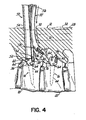
- Fig. 4 shows one example of such an embodiment, with prime (') marks being used to designate structure that slightly differs from Fig. 3A .
- a surgeon may slide the delivery device 70' along the first positioning tool 50 to facilitate directing the delivery device 70' generally toward the second vertebral anchor 16.
- the delivery device 70' may be formed with a desired degree of curvature.
- the surgeon can guide the delivery device 70' along a path corresponding to its curvature.
- the strength of the delivery device 70 and its ability to withstand compression forces enables it to be advanced through tissue 72 in the patient's body 12 without being significantly deflected.
- a first portion 74 of the connecting element 22 may remain exposed when the connecting element 22 is inserted with the delivery device 70, but does not extend an appreciable distance so that the connecting element 22 does not adversely affect the insertion of the delivery device 70 through the tissue 72.
- the end portion 71 is in the form of a bullet-shaped nose (as shown), the shape and rigidity of the nose may facilitate movement of the connecting element 22 through the tissue 72.
- the delivery device 70 may be manipulated while being advanced along the first positioning tool 50 until the first portion 74 of the connecting element 22 is received in or near the receiving channel 42 of the second vertebral anchor 16, as shown in Fig. 3B . To this end, the delivery device 70 may be passed through the first incision 30 and directed toward the second vertebral anchor 16 until it abuts and/or confronts a generally flat surface 76 defined by the head 36. If the first portion 74 of the connecting element 22 remains exposed during this insertion, the first portion 74 may be received in the receiving channel 42 of the second vertebral anchor 16 without additional steps. If the delivery device 70 is positioned over the first portion 74 during insertion, the connecting element 22 may then be pushed through the delivery device 70 until the first portion 74 extends through the receiving channel 42.
- the delivery device 70 may be constructed from a flexible shape memory material, such as Nitinol.
- the shape memory material may be temperature-dependent such that the delivery device 70 has a normally straight configuration at room temperature, but assumes a curved configuration once placed within the patient's body 12 (where it is exposed to body temperatures).
- the delivery device 70 may still be passed through the patient's body 12 and directed generally toward the second vertebral anchor 16 while using the first positioning tool 50 for guidance and/or leverage.
- the delivery device 70 may not be directly aligned with the receiving channel 42 after directing the connecting element 22 toward the second vertebral anchor 16. If necessary or desired, additional tools (not shown) may be inserted through the second incision 32 to help properly position the first portion 74 within the receiving channel 42. Because the receiving channel 42 is open, the first portion 74 may be easily received by the second vertebral anchor 16 in a top-loading fashion. Radiographic images can be obtained to determine the proper positioning of the first portion 74 of the connecting element 22.
- the end portion 71 can be formed of a material that facilitates the identification of the proper placement of the connecting element 22.
- a second positioning tool 80 may be inserted through the second incision 32 and along a path generally toward the second vertebral anchor 16.
- the second positioning tool 80 includes a second end 82 configured to be coupled to the head 36 of the second vertebral anchor 16 in the same manner as the first end 52 of the first positioning tool 50 and the head 36 of the first vertebral anchor 14.
- a fastener 84 may then be passed through the second incision 32 and percutaneously delivered to the receiving channel 42.
- the fastener 84 may be delivered through an elongated slot 86 defined in the second positioning tool 80, as shown in Fig. 3B .
- the fastener 84 is secured within the receiving channel 42 so that the first portion 74 of the connecting element 22 is retained (e.g., compressed) between the fastener 84 and the second vertebral anchor 16.
- the fastener 84 is a set screw having external threads 90 that engage internal threads 92 ( Fig. 2 ) provided in the receiving channel 42 of the second vertebral anchor 16.
- the fastener 84 maybe delivered through the second positioning tool 80 and tightened using a driving tool 94, as shown in Fig. 3C (with the second positioning tool 80 shown in phantom for clarity).
- the second positioning tool 80 stabilizes the second vertebral anchor 16 as the set screw is rotated to engage the internal threads 92.
- the second positioning tool 80 may serve as an anti-torque instrument to counteract the forces applied by the driving tool 94.
- the first portion 74 of the connecting element 22 maybe secured to the head 36 of the second vertebral anchor 16 using different types of fasteners or other elements.
- the second vertebral anchor 16 may alternatively be shaped to cooperate with a cap (not shown) for retaining the first portion 74 of the connecting element 22.
- the second positioning tool 80 may be removed from the patient's body 12 through the second incision 32.
- the delivery device 70 may also be removed from the connecting element 22 to expose a second portion 96 of the connecting element 22. As shown in Fig. 3C , the delivery device 70 is removed through the first incision 30 in the patient's skin 28.
- the tissue 72 surrounding the connecting element 22 effectively maintains the connecting element 22 in position while the delivery device 70 is removed.
- Fig. 3D illustrates the spacer 24 being advanced through the first incision 30 and over the connecting element 22.
- the second positioning tool 80 and driving tool 94 may be removed before or after the spacer 24 is advanced.
- the first positioning tool 50 is shown as remaining within the patient's body 12, it will be appreciated that the first positioning tool 50 may alternatively be removed through the first incision 30 prior to this step as well.
- the spacer 24 may be advanced along the length of the connecting element 22 until a first end 98 of the spacer 24 confronts the generally flat surface 76 of the head 36.
- a pushing instrument (not shown) may be used to aid in movement of the spacer 24 through tissue 72 and along the connecting element 22.
- the pushing instrument may be inserted through the first incision 30 and adapted to engage a second end 100 of the spacer 24 to push the spacer 24 generally in the direction of arrow 102.
- the pushing instrument may be adapted to engage a portion of the spacer 24 between the first and second ends 98,100 to adjust the orientation of the spacer 24 relative to the first vertebral anchor 14 and/or second vertebral anchor 16.
- the pushing instrument may be inserted through a separate incision (not shown) or the second incision 32.
- the surgeon can determine the distance between vertebral anchors 14,16 and size the spacer 24 outside the patient to a length that achieves a desired patient outcome. For example, if the surgeon hopes to achieve posterior distraction between vertebrae, the spacer 24 can be sized greater than the distance between opposing surfaces of the vertebral anchors 14,16 upon which the spacer 24 engages. This measurement may be made, for example and without limitation, based on the distance outside the patient between instruments engaging the anchors or through radiographic means.
- the second portion 96 of the connecting element 22 may extend generally toward the first incision 30 before being received in the receiving channel 42 of the first vertebral anchor 14 or the elongated slot 58 of the first positioning tool 50.
- the second portion 96 of the connecting element 22 may therefore be moved to a desired position relative to the first vertebral anchor 14 by manipulating the connecting element 22 by hand or by using one or more additional tools.
- a tensioning tool 150 configured to cooperate with the first positioning tool 50 may be inserted through the first incision 30.
- the tensioning tool 150 includes a stabilizing element 152 having a top portion 154 aligned generally above the second end 100 of the spacer 24.
- a bottom portion 156 of the tensioning tool 150 may be inserted through the elongated slot 58 to an opposite side of the first positioning tool 50 to direct the second portion 96 of the connecting element 22 into the receiving channel 42 ( Fig. 2 ) of the first vertebral anchor 14.
- the spacer 24 is properly positioned between the first and second vertebral anchors 14,16.
- Additional length 104 of the connecting element 22 extending from the second portion 96 may curve upwardly and around the bottom portion 156 of the stabilizing element 152 so as to extend into the elongated slot 58 of the first positioning tool 50. Indeed, the additional length may continue to extend out of the elongated slot 58 and through the top portion 154 of the stabilizing element 152. While maintaining the bottom portion 156 of the stabilizing element 152 in position (so that the second portion 96 of the connecting element 22 is maintained in the receiving channel 42), the additional length 104 may be pulled to place the connecting element 22 in tension. The additional length 104 may be pulled manually by hand or by using a surgical tool.
- the tensioning tool 150 further includes a gripping element 158 having a first arm 160 configured to clamp or otherwise securely grip the connecting element 22 after the additional length 104 extends through the stabilizing element 152. As shown in Figs. 3E and 3F , a surgeon may pivot the first arm 160 relative to a second arm 162 of the gripping element 158 to mechanically pull the connecting element 22 through the stabilizing element 152.
- the second portion 96 is secured to the first vertebral anchor 14.
- the second portion 96 may be secured in a manner similar to the first portion 74.
- a fastener 106 such as a set screw, may be inserted through the first incision 30 and percutaneously delivered to the receiving channel 42 of the first vertebral anchor 14. More specifically, the fastener 106 may be delivered through the stabilizing element 152 and first positioning tool 50 using a driving tool 170, which maybe similar to the driving tool 94 ( Fig. 3C ). A handle 172 of the driving tool 170 is rotated to drive the fastener 106 into engagement with the internal threads 92 ( Fig. 2 ) provided in the receiving channel 42.
- the threaded engagement secures the second portion 96 of the connecting element 22 relative to the first vertebral anchor 14.
- the connecting element 22 may then be cut proximate the first vertebral anchor 14, and the first positioning tool 50 and the tensioning tool 150 may be removed from the patient's body 12 through the first incision 30. This results in the arrangement shown in Fig. 3G .
- Fig . 5 shows a delivery device 200 according to claim 1.
- the delivery device 200 includes a first sheath member 202 coupled to a second sheath member 204 at an articulating joint 206.
- the first sheath member 202 is hollow so that it may be positioned over the connecting element 22 in the same manner as the delivery device 70 ( Fig. 3 ).
- the second sheath member 204 is also hollow, and may further include a slot 208 for accommodating the connecting element 22.
- the second sheath member 204 may be solid so that the connecting element 22 may only extend through the first sheath member 202.
- the first sheath member 202 may pivot relative to the second sheath member 204 to change the angle defined between the two components.
- the articulating joint 206 may be configured to lock the first sheath member 202 at several different angles relative to the second sheath member 204. Any suitable locking technique may be used.
- the articulating joint 206 may include a ratcheting mechanism, locking pin, or other structure capable of locking the first sheath member 202 at one or more angles relative to the second sheath member 204.
- the first sheath member 202 may be designed to have an adjustable length.
- the first sheath member 202 may include telescoping or extendable sections (not shown).
- Figs. 5A-5C illustrate the delivery device 200 being used to deliver the connecting element 22 to within the patient's body 12, with like reference numbers being used to refer to like structure from Figs. 3A-3G .
- the delivery device 200 may be inserted through the first incision 30 within or near the first positioning tool 50. Additionally, the first sheath member 202 and/or second sheath member 204 may be at least partially received in the elongated slot 58 of the first positioning tool 50 to help guide the first sheath member 202 generally toward the second vertebral anchor 16.
- Figs. 5A-5C illustrate the delivery device 200 being used to deliver the connecting element 22 to within the patient's body 12, with like reference numbers being used to refer to like structure from Figs. 3A-3G .
- the delivery device 200 may be inserted through the first incision 30 within or near the first positioning tool 50. Additionally, the first sheath member 202 and/or second sheath member 204 may be at least partially received in the elongated slot 58 of the first positioning
- the delivery device 200 may be used in a manner similar to the delivery device 70 ( Fig. 3A ) or the delivery device 70' ( Fig. 4 ) depending on the diameters of the first sheath member 202 and second sheath member 204.
- the delivery device 200 is manipulated differently when passed through the first incision 30. This difference is due to the first sheath member 202 being positioned at an angle relative to the second sheath member 204 (by means of the articulating joint 206). In some instances it may be easier to use the delivery device 200 to delivery the first portion 74 of the connecting element 22 to the second vertebral anchor 16, whereas in other instances it may be easier to use the delivery device 70. Note that the angle of the first sheath member 202 relative to the second sheath member 204 may be adjusted one or more times during the insertion of the delivery device 200. Alternatively, the angle may be adjusted prior to insertion and maintained throughout the procedure.
- the first portion 74 may be secured to the second vertebral anchor 16 in the same manner discussed above with reference to Fig. 3C .
- the delivery device 200 may then be removed from the patient's body 12 by retracting it back through the first incision 30 and over the connecting element 22. As with the insertion procedure, the angle of the first sheath member 202 relative to the second sheath member 204 may be adjusted before or during this removal procedure.
- the spacer 24 may be advanced over the connecting element 22 and the second portion 96 may be secured to the first vertebral anchor 14, as discussed above with reference to Figs. 3D-3G .
- Figs. 6A-6C illustrate a third vertebra 300 positioned between the first and second vertebrae 18, 20 and a method of installing a stabilization system to effect treatment across the first, second, and third vertebrae 18, 20, 300. Because the techniques and tools are similar to those discussed above with reference to Figs. 3A-3G , like reference numbers are used to refer to like structure.
- a third vertebral anchor 302 may be inserted through a third incision 304 at a third location on the patient's skin 28 and ultimately secured to the third vertebra 300 using conventional techniques.
- a third positioning tool 306 may then be inserted through the third incision 304 and generally toward the third vertebral anchor 302.
- the third vertebral anchor 302 may be a pedicle screw having substantially the same construction as the first and second vertebral anchors 14,16, and the third positioning tool 306 may have substantially the same construction as the first and second positioning tools 50, 80.
- the third positioning tool 306 may include an elongated slot or cavity (not shown).
- a third end 310 of the third positioning tool 306 may be coupled to the head 36 of the third vertebral anchor 302 using the techniques discussed above with reference to the first and second positioning tools 50, 80.
- the delivery device 70 and connecting element 22 may be inserted through the first incision 30.
- the first positioning tool 50 is used to facilitate directing the delivery device 70 generally toward the third vertebral anchor 302.
- the connecting element 22 may be pushed through the delivery device 70 so that a third portion 312 (located between the first portion 74 and second portion 96) extends through the receiving channel 42 ( Fig. 2 ) in the third vertebral anchor 302 or through the elongated slot of the third positioning tool 306.
- the connecting element 22 may have a preformed curvature so that it curves upwardly and generally toward the second incision 32 when further pushed through the delivery device 70.
- the first portion 74 may be received in the elongated slot 86 and/or ultimately exit the patient's body 12 through the second incision 32.
- the connecting element 22 approaches the second vertebral anchor 16 when further pushed through the delivery device 70. The first portion 74 may then be received in the elongate slot 86 and pulled up through the second incision 32.
- the third portion 312 may be secured to the third vertebral anchor 302 using any suitable technique.
- the third portion 312 maybe retained in the receiving channel 42 ( Fig. 2 ) of the third vertebral anchor 302 by passing a fastener 314, such as a set screw, through the elongated slot or cavity of the third positioning tool 306 and securing the fastener 314 within the receiving channel 42 over the third portion 312.
- the delivery device 70 may then be pulled back through the first incision 30 and removed from the connecting element 22 so as to expose the second portion 96.
- the third portion 312 is secured within the patient's body 12 whereas the first and second portions 74, 96 are positioned in or proximate the elongated slots 58, 86, respectively.
- Such an arrangement allows spacers, like spacer 24, to be placed over the connecting element 22 and for the first and second portions 74, 96 to be secured to the first and second vertebral anchors 14,16 using the techniques described above.
- the tensioning tool 150 ( Figs. 3E and 3F ) and fastener 106 may be used to secure the second portion 96 to the first vertebral anchor 14, and the tensioning tool 150 and fastener 84 may be used to secure the first portion 74 to the second vertebral anchor 16.
- Any additional length of the connecting element 22 extending beyond the first and second portions 74, 96 may be cut proximate the first and second vertebral anchors 14,16 to complete the installation procedure.
- the surgeon can be provided with several spacers each having different elastic characteristics for the multi-level construct shown in Figs. 6A-6C .
- the surgeon can choose the spacer, like spacer 24, based on the patient's condition and include spacers having different elastic characteristics in a single patient, if desired.
- the spacer between anchors 14 and 302 can be a more elastic material and the spacer between anchors 302 and 16 can be a more rigid material.
- the surgeon can be provided a single connecting element that has varying elastic characteristics over its length for the multi-level construct shown in Figs. 6A-6C .
- the surgeon may then implant the elastically varied connecting element in a desired location to provide a desired result in the patient.
- the elastically varied connecting element can include radiographic markers that assist the surgeon in identifying the differing areas of elasticity when the connecting element is implanted in the patient to provide differing characteristics of the stabilization system 10 at adjacent levels.
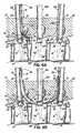
- Figs. 7A-7C illustrate another method of installing the stabilization system 10 of the invention for the purpose of multi-level treatment. Because the method uses many of the same components as the method shown in Figs. 6A-6C , like reference numbers are used to refer to like structure. Additionally, only the differences between the methods are described below.
- a delivery device 400 is positioned over the connecting element 22.
- the delivery device 400 comprises a first sheath member 402 and a second sheath member 404, which may or may not have substantially the same shape and/or length.
- the delivery device 400 and connecting element 22 are inserted through the first incision 30 and along at least a portion of the first positioning tool 50 before the third end 310 of the third positioning tool 306 is coupled to the head 36 of the third vertebral anchor 302.
- FIG. 7A shows the first sheath member 402 spaced apart from the second sheath member 404 such that the third portion 312 of the connecting element 22 is exposed within the patient's body 12, the second sheath member 404 may alternatively be advanced over the third portion 312 during this insertion so as to abut the first sheath member 402.
- the first sheath member 402 is directed past the third vertebral anchor 302 so that the third portion 312 of the connecting element 22 is positioned proximate the head 36 of the third vertebral anchor 302. If the second sheath member 404 abuts the first sheath member 402, the second sheath member 404 is retracted to expose the third portion 312.
- the third positioning tool 306 may then be directed downwardly to the third vertebral anchor 302 so that the third portion 312 is received in the elongated slot or cavity of the third positioning tool 306. After coupling the third end 310 of the third positioning tool 306 to the head 36 of the third vertebral anchor 302, the third portion 312 may be secured to the third vertebral anchor 302 using the fastener 314 or any other suitable technique.
- the first sheath member 402 has a preformed curvature so that it curves slightly upwardly toward the patient's skin 28 after being advanced past the third vertebral anchor 302.
- the first sheath member 402 may eventually contact the second positioning tool 80, which may be used to facilitate directing the first sheath member 402 to the second incision 32.
- the first sheath member 402 may be at least partially received in the elongated slot 86 and may slide along the elongated slot 86 when further advanced past the third vertebral anchor 302.
- the first and second sheath members 402, 404 may be removed from the patient's body 12 and connecting element 22. More specifically, the first sheath member 402 may be removed through the second incision 32 and from the connecting element 22 so as the leave the first portion 74 positioned in or proximate the elongated slot 86. The second sheath member 404 may be removed back through the first incision 30 and off the connecting element 22 so as to leave the second portion 96 positioned in or proximate the elongated slot 58.
- first portion 74 may be secured to the second vertebral anchor 16 and the second portion 96 may be secured to the first vertebral anchor 14 using any of the techniques discussed above. It will be appreciated that the third positioning tool 306 may be removed through the third incision 304 before or after removing the first and second sheath members 402, 404 and/or securing the first and second portions 74, 96.
- Figs. 8A-8D illustrate yet another method of installing the stabilization system 10 of the invention for the purpose of multi-level treatment.
- Like reference numbers are once again used to refer to like structure from the other embodiments discussed above.
- the first, second, and third positioning tools 50,80, 306 are inserted through the respective first, second, and third incisions 30, 32, 304 and coupled to the respective first, second, and third vertebral anchors 14,16, 302.
- the connecting element 22 is inserted through the elongated slot in the third positioning tool 306 so that the first portion 74 extends generally toward the first positioning tool 50 and the second portion 96 extends generally toward the second positioning tool 80.
- a first delivery device 500 may then be positioned over the first portion 74 and a second delivery device 502 may be positioned over the second portion 96.
- the first and second delivery devices 500, 502 may be used to direct the first and second portions 74, 96 through the patient's body 12.
- the first delivery device 500 and the first portion 74 of the connecting element 22 may be inserted through the third incision 304 and along at least a portion of the third positioning tool 306.
- the third positioning tool 306 may be used for guidance and/or leverage to help direct the first delivery device 500 and first portion 74 along a path through the patient's body 12 and generally toward the first vertebral anchor 14.
- the third positioning tool 306 and its elongated slot may be used in a way similar to which the first positioning tool 50 and elongated slot 58 are used in the other embodiments discussed above.
- the first delivery device 500 contacts the first vertebral anchor 14 and/or first positioning tool 50 it may be directed upwardly toward the first incision 30.
- the first delivery device 500 may slide along the elongated slot 58 and exit the patient's body 12 through the first incision 30 when sufficiently advanced through the third incision 304.
- the tissue 72 within the patient's body 12 helps maintain the first delivery device 500 and connecting element 22 within the patient's body 12 between the first and third incisions 30, 304.
- the second delivery device 502 and second portion 96 of the connecting element 22 may be inserted into the patient's body 12 in a similar manner. Specifically, the second delivery device 502 and second portion 96 may be inserted through the third incision 304 and generally toward the second vertebral anchor 16, using the third positioning tool 306 for guidance and/or leverage when needed. When the second delivery device 502 contacts the second vertebral anchor 16 and/or second positioning tool 80, it may be directed upwardly toward the second incision 32. For example, the second delivery device 502 may slide along the elongated slot 86 toward the second incision 32.
- the third portion 312 of the connecting element 22 may be pushed downwardly through the third positioning tool 306 and into the receiving channel 42 ( Fig. 2 ) in the head 36 of the third vertebral anchor 302. Any suitable tool may be used to push the third portion 312, including the fastener 314 and driving tool 94 ultimately used to retain the third portion 312 within the receiving channel 42.
- the first and second delivery devices 500, 502 are further advanced into the patient's body 12 as well.
- the first delivery device 500 eventually extends from the third vertebral anchor 302 to the first incision 30 and the second delivery device 502 eventually extends from the third vertebral anchor 302 to the second incision 32.
- the first and second delivery devices 500, 502 may be removed from the patient's body 12 through the respective first and second incisions 30, 32. Removing the first and second delivery devices 500, 502 exposes the first and second portions 74, 96, which may be secured to the respective first and second vertebral anchors 14,16 using any of the techniques discussed above.
- the invention can be used in a method as defined below under item 1, this method having several aspects as mentioned below under items 2 to 21 and which are here referred to as "items”.
Landscapes
- Health & Medical Sciences (AREA)
- Orthopedic Medicine & Surgery (AREA)
- Life Sciences & Earth Sciences (AREA)
- Surgery (AREA)
- Neurology (AREA)
- Heart & Thoracic Surgery (AREA)
- Engineering & Computer Science (AREA)
- Biomedical Technology (AREA)
- Nuclear Medicine, Radiotherapy & Molecular Imaging (AREA)
- Medical Informatics (AREA)
- Molecular Biology (AREA)
- Animal Behavior & Ethology (AREA)
- General Health & Medical Sciences (AREA)
- Public Health (AREA)
- Veterinary Medicine (AREA)
- Surgical Instruments (AREA)
- Prostheses (AREA)
Claims (7)
- System für dynamisches Stabilisierungssystem einer Wirbelsäule eines Patienten, umfassend:einen ersten und zweiten Wirbelanker (14, 16), die derart konfiguriert sind, dass sie an einer ersten und zweiten Stelle (18, 20) in dem Körper eines Patienten befestigt werden können;ein Verbindungselement (22) mit einem ersten und zweiten Abschnitt (74, 96), die zur Aufnahme durch den ersten bzw. zweiten Wirbelanker konfiguriert sind;eine Liefervorrichtung (200), die zur Positionierung über dem Verbindungselement konfiguriert ist, wobei die Liefervorrichtung eine Steifigkeit besitzt, die größer als die des Verbindungselements ist, und entlang des Verbindungselements zurückziehbar ist; undein erstes Positionierungswerkzeug (50) mit einem Ende, das zur Kopplung mit dem ersten Wirbelanker konfiguriert ist, und einem länglichen Schlitz (58), der derart konfiguriert ist, ein Führen der Liefervorrichtung und des Verbindungselements entlang eines Pfads allgemein zu dem zweiten Wirbelanker zu unterstützen,dadurch gekennzeichnet, dassdie Liefervorrichtung ein zweites Hülsenelement und ein erstes Hülsenelement (202) aufweist, das mit dem zweiten Hülsenelement (204) an einer Gelenkverbindung (206) gekoppelt ist, so dass der Winkel des ersten Hülsenelements relativ zu dem zweiten Hülsenelement eingestellt werden kann,wobei das erste und zweite Hülsenelement zur Positionierung über dem Verbindungselement beide hohl sind.
- System nach Anspruch 1,
wobei der längliche Schlitz eine erste Breite besitzt und die Liefervorrichtung einen ersten Durchmesser besitzt, der größer als die erste Breite ist. - System nach einem der Ansprüche 1 oder 2,
wobei die Gelenkverbindung derart konfiguriert ist, das erste Hülsenelement unter verschiedenen Winkeln relativ zu dem zweiten Hülsenelement zu verriegeln. - System nach einem der Ansprüche 1 bis 3,
wobei der erste Wirbelanker im Wesentlichen entlang einer Achse ausgerichtet ist, wobei das Positionierungswerkzeug zur Kopplung mit dem ersten Wirbelanker unter einem Winkel zu der Achse konfiguriert ist. - System nach einem der Ansprüche 1 bis 4, ferner mit:einem Abstandhalter (24), der derart konfiguriert ist, dass er um das Verbindungselement herum aufnehmbar ist, und so bemessen ist, dass er zwischen den ersten und zweiten Wirbelanker passt.
- System nach einem der Ansprüche 1 bis 5,
wobei die Liefervorrichtung aus Polyethylenrohr ausgebildet ist. - System nach einem der Ansprüche 1 bis 6,
wobei das Verbindungselement ein Cord ist.
Applications Claiming Priority (2)
| Application Number | Priority Date | Filing Date | Title |
|---|---|---|---|
| US12/025,984 US9277940B2 (en) | 2008-02-05 | 2008-02-05 | System and method for insertion of flexible spinal stabilization element |
| PCT/US2008/085002 WO2009099477A2 (en) | 2008-02-05 | 2008-11-26 | System and method for insertion of flexible spinal stabilization element |
Publications (2)
| Publication Number | Publication Date |
|---|---|
| EP2254494A2 EP2254494A2 (de) | 2010-12-01 |
| EP2254494B1 true EP2254494B1 (de) | 2012-06-20 |
Family
ID=40932426
Family Applications (1)
| Application Number | Title | Priority Date | Filing Date |
|---|---|---|---|
| EP08872028A Not-in-force EP2254494B1 (de) | 2008-02-05 | 2008-11-26 | System zur einführung eines flexiblen wirbelsäulen-stabilisationselements |
Country Status (6)
| Country | Link |
|---|---|
| US (4) | US9277940B2 (de) |
| EP (1) | EP2254494B1 (de) |
| CN (1) | CN102014776A (de) |
| AU (1) | AU2008349784A1 (de) |
| CA (1) | CA2715243A1 (de) |
| WO (1) | WO2009099477A2 (de) |
Families Citing this family (77)
| Publication number | Priority date | Publication date | Assignee | Title |
|---|---|---|---|---|
| US7833250B2 (en) | 2004-11-10 | 2010-11-16 | Jackson Roger P | Polyaxial bone screw with helically wound capture connection |
| US8353932B2 (en) | 2005-09-30 | 2013-01-15 | Jackson Roger P | Polyaxial bone anchor assembly with one-piece closure, pressure insert and plastic elongate member |
| US7862587B2 (en) | 2004-02-27 | 2011-01-04 | Jackson Roger P | Dynamic stabilization assemblies, tool set and method |
| US8292926B2 (en) | 2005-09-30 | 2012-10-23 | Jackson Roger P | Dynamic stabilization connecting member with elastic core and outer sleeve |
| US10258382B2 (en) | 2007-01-18 | 2019-04-16 | Roger P. Jackson | Rod-cord dynamic connection assemblies with slidable bone anchor attachment members along the cord |
| US10729469B2 (en) | 2006-01-09 | 2020-08-04 | Roger P. Jackson | Flexible spinal stabilization assembly with spacer having off-axis core member |
| US8876868B2 (en) | 2002-09-06 | 2014-11-04 | Roger P. Jackson | Helical guide and advancement flange with radially loaded lip |
| US7621918B2 (en) | 2004-11-23 | 2009-11-24 | Jackson Roger P | Spinal fixation tool set and method |
| US7377923B2 (en) | 2003-05-22 | 2008-05-27 | Alphatec Spine, Inc. | Variable angle spinal screw assembly |
| US8936623B2 (en) | 2003-06-18 | 2015-01-20 | Roger P. Jackson | Polyaxial bone screw assembly |
| US8366753B2 (en) | 2003-06-18 | 2013-02-05 | Jackson Roger P | Polyaxial bone screw assembly with fixed retaining structure |
| US7776067B2 (en) | 2005-05-27 | 2010-08-17 | Jackson Roger P | Polyaxial bone screw with shank articulation pressure insert and method |
| US7766915B2 (en) | 2004-02-27 | 2010-08-03 | Jackson Roger P | Dynamic fixation assemblies with inner core and outer coil-like member |
| US8092500B2 (en) | 2007-05-01 | 2012-01-10 | Jackson Roger P | Dynamic stabilization connecting member with floating core, compression spacer and over-mold |
| US7967850B2 (en) | 2003-06-18 | 2011-06-28 | Jackson Roger P | Polyaxial bone anchor with helical capture connection, insert and dual locking assembly |
| US7955355B2 (en) * | 2003-09-24 | 2011-06-07 | Stryker Spine | Methods and devices for improving percutaneous access in minimally invasive surgeries |
| US7179261B2 (en) | 2003-12-16 | 2007-02-20 | Depuy Spine, Inc. | Percutaneous access devices and bone anchor assemblies |
| US7527638B2 (en) | 2003-12-16 | 2009-05-05 | Depuy Spine, Inc. | Methods and devices for minimally invasive spinal fixation element placement |
| US11419642B2 (en) | 2003-12-16 | 2022-08-23 | Medos International Sarl | Percutaneous access devices and bone anchor assemblies |
| AU2004317551B2 (en) | 2004-02-27 | 2008-12-04 | Roger P. Jackson | Orthopedic implant rod reduction tool set and method |
| US7160300B2 (en) | 2004-02-27 | 2007-01-09 | Jackson Roger P | Orthopedic implant rod reduction tool set and method |
| US9050148B2 (en) | 2004-02-27 | 2015-06-09 | Roger P. Jackson | Spinal fixation tool attachment structure |
| US8152810B2 (en) * | 2004-11-23 | 2012-04-10 | Jackson Roger P | Spinal fixation tool set and method |
| US11241261B2 (en) | 2005-09-30 | 2022-02-08 | Roger P Jackson | Apparatus and method for soft spinal stabilization using a tensionable cord and releasable end structure |
| US7651502B2 (en) | 2004-09-24 | 2010-01-26 | Jackson Roger P | Spinal fixation tool set and method for rod reduction and fastener insertion |
| US8926672B2 (en) | 2004-11-10 | 2015-01-06 | Roger P. Jackson | Splay control closure for open bone anchor |
| US9216041B2 (en) | 2009-06-15 | 2015-12-22 | Roger P. Jackson | Spinal connecting members with tensioned cords and rigid sleeves for engaging compression inserts |
| US9393047B2 (en) | 2009-06-15 | 2016-07-19 | Roger P. Jackson | Polyaxial bone anchor with pop-on shank and friction fit retainer with low profile edge lock |
| US8444681B2 (en) | 2009-06-15 | 2013-05-21 | Roger P. Jackson | Polyaxial bone anchor with pop-on shank, friction fit retainer and winged insert |
| US9168069B2 (en) | 2009-06-15 | 2015-10-27 | Roger P. Jackson | Polyaxial bone anchor with pop-on shank and winged insert with lower skirt for engaging a friction fit retainer |
| US7901437B2 (en) | 2007-01-26 | 2011-03-08 | Jackson Roger P | Dynamic stabilization member with molded connection |
| US7658739B2 (en) | 2005-09-27 | 2010-02-09 | Zimmer Spine, Inc. | Methods and apparatuses for stabilizing the spine through an access device |
| US8105368B2 (en) | 2005-09-30 | 2012-01-31 | Jackson Roger P | Dynamic stabilization connecting member with slitted core and outer sleeve |
| EP2088945A4 (de) | 2006-12-08 | 2010-02-17 | Roger P Jackson | Werkzeugsystem für dynamische wirbelsäulenimplantate |
| US8366745B2 (en) | 2007-05-01 | 2013-02-05 | Jackson Roger P | Dynamic stabilization assembly having pre-compressed spacers with differential displacements |
| US8475498B2 (en) | 2007-01-18 | 2013-07-02 | Roger P. Jackson | Dynamic stabilization connecting member with cord connection |
| US10383660B2 (en) | 2007-05-01 | 2019-08-20 | Roger P. Jackson | Soft stabilization assemblies with pretensioned cords |
| US9277940B2 (en) | 2008-02-05 | 2016-03-08 | Zimmer Spine, Inc. | System and method for insertion of flexible spinal stabilization element |
| EP2442739A1 (de) | 2008-08-01 | 2012-04-25 | Jackson, Roger P. | Langes verbindungselement mit ummantelten spannseilen |
| US8137355B2 (en) | 2008-12-12 | 2012-03-20 | Zimmer Spine, Inc. | Spinal stabilization installation instrumentation and methods |
| EP2757988A4 (de) | 2009-06-15 | 2015-08-19 | Jackson Roger P | Polyaxialer knochenanker mit einem aufsatzschaft und einem flügeleinsatz mit einer durch reibung eingepassten kompressiven spannzange |
| US9668771B2 (en) | 2009-06-15 | 2017-06-06 | Roger P Jackson | Soft stabilization assemblies with off-set connector |
| US8998959B2 (en) | 2009-06-15 | 2015-04-07 | Roger P Jackson | Polyaxial bone anchors with pop-on shank, fully constrained friction fit retainer and lock and release insert |
| US11229457B2 (en) | 2009-06-15 | 2022-01-25 | Roger P. Jackson | Pivotal bone anchor assembly with insert tool deployment |
| US20110009906A1 (en) * | 2009-07-13 | 2011-01-13 | Zimmer Spine, Inc. | Vertebral stabilization transition connector |
| US9211144B2 (en) * | 2009-09-09 | 2015-12-15 | Globus Medical, Inc. | Spine surgery device and method |
| EP2485654B1 (de) | 2009-10-05 | 2021-05-05 | Jackson P. Roger | Polyaxialer knochenanker mit nicht schwenkbarem halter und schaftüberzug sowie optional mit reibungsfritte |
| US8328849B2 (en) * | 2009-12-01 | 2012-12-11 | Zimmer Gmbh | Cord for vertebral stabilization system |
| US8740945B2 (en) | 2010-04-07 | 2014-06-03 | Zimmer Spine, Inc. | Dynamic stabilization system using polyaxial screws |
| US8382803B2 (en) | 2010-08-30 | 2013-02-26 | Zimmer Gmbh | Vertebral stabilization transition connector |
| WO2012033532A1 (en) | 2010-09-08 | 2012-03-15 | Roger Jackson P | Dynamic stabilization members with elastic and inelastic sections |
| US8968319B2 (en) | 2011-06-20 | 2015-03-03 | Spinefrontier, Inc | Methods, tools and devices for spinal fixation |
| WO2013106217A1 (en) | 2012-01-10 | 2013-07-18 | Jackson, Roger, P. | Multi-start closures for open implants |
| US8911478B2 (en) | 2012-11-21 | 2014-12-16 | Roger P. Jackson | Splay control closure for open bone anchor |
| US10058354B2 (en) | 2013-01-28 | 2018-08-28 | Roger P. Jackson | Pivotal bone anchor assembly with frictional shank head seating surfaces |
| US8852239B2 (en) | 2013-02-15 | 2014-10-07 | Roger P Jackson | Sagittal angle screw with integral shank and receiver |
| US9554835B2 (en) | 2013-03-14 | 2017-01-31 | Warsaw Orthopedic, Inc. | Surgical implant system and method |
| US9387018B2 (en) | 2013-03-14 | 2016-07-12 | Warsaw Orthopedic, Inc. | Surgical implant system and method |
| WO2014143862A1 (en) * | 2013-03-15 | 2014-09-18 | Shriners Hospitals For Children | Methods and techniques for spinal surgery |
| US9566092B2 (en) | 2013-10-29 | 2017-02-14 | Roger P. Jackson | Cervical bone anchor with collet retainer and outer locking sleeve |
| US9717533B2 (en) | 2013-12-12 | 2017-08-01 | Roger P. Jackson | Bone anchor closure pivot-splay control flange form guide and advancement structure |
| US9451993B2 (en) | 2014-01-09 | 2016-09-27 | Roger P. Jackson | Bi-radial pop-on cervical bone anchor |
| US10064658B2 (en) | 2014-06-04 | 2018-09-04 | Roger P. Jackson | Polyaxial bone anchor with insert guides |
| US9597119B2 (en) | 2014-06-04 | 2017-03-21 | Roger P. Jackson | Polyaxial bone anchor with polymer sleeve |
| US9724131B2 (en) | 2014-09-25 | 2017-08-08 | DePuy Synthes Products, Inc. | Spinal connectors and related methods |
| EP3229714B1 (de) | 2014-12-09 | 2022-03-02 | Heflin, John, A. | System zur wirbelsäulenausrichtung |
| US9924983B2 (en) * | 2015-02-11 | 2018-03-27 | Warsaw Orthopedic, Inc. | Spinal correction method and system |
| CN106361413A (zh) * | 2015-07-24 | 2017-02-01 | 镱钛科技股份有限公司 | 穿刺导引器 |
| EP3509506B1 (de) | 2016-09-07 | 2021-03-03 | Vertos Medical, Inc. | Instrumente für perkutane seitliche vertiefung |
| US10456174B2 (en) | 2017-07-31 | 2019-10-29 | Medos International Sarl | Connectors for use in systems and methods for reducing the risk of proximal junctional kyphosis |
| US10463403B2 (en) | 2017-07-31 | 2019-11-05 | Medos International Sarl | Systems and methods for reducing the risk of proximal junctional kyphosis using a bone anchor or other attachment point |
| US10939941B2 (en) | 2017-08-29 | 2021-03-09 | Zimmer Biomet Spine, Inc. | Surgical cord tensioning devices, systems, and methods |
| US10905474B2 (en) | 2017-08-29 | 2021-02-02 | Zimmer Biomet Spine, Inc. | Surgical cord tensioning devices, systems, and methods |
| US11020149B2 (en) * | 2018-02-28 | 2021-06-01 | Globus Medical Inc. | Scoliosis correction systems, methods, and instruments |
| WO2020077029A1 (en) * | 2018-10-10 | 2020-04-16 | Zimmer Biomet Spine, Inc. | Surgical cord tensioning devices and systems |
| US11547452B2 (en) | 2020-12-17 | 2023-01-10 | Institute for Spine & Scollosis, P.A. | Method for improved spinal correction surgery implementing non-fusion anterior scoliosis correction techniques with vertebrae de-rotation |
| US12465342B2 (en) | 2022-06-16 | 2025-11-11 | Vertos Medical, Inc. | Integrated instrument assembly |
Family Cites Families (173)
| Publication number | Priority date | Publication date | Assignee | Title |
|---|---|---|---|---|
| US2248054A (en) | 1939-06-07 | 1941-07-08 | Becker Joseph | Screw driver |
| NL7610576A (en) | 1976-09-23 | 1978-03-29 | Gerard Hendrik Slot | Spinal column repositioning system - uses tongs to position screws in column sections before securing to rope |
| FR2521478A1 (fr) | 1982-02-17 | 1983-08-19 | Aerospatiale | Dispositif de pose automatique des systemes d'assemblage |
| DE3614101C1 (de) | 1986-04-25 | 1987-10-22 | Juergen Prof Dr Med Harms | Pedikelschraube |
| ZA871322B (en) | 1987-02-24 | 1987-10-28 | Alexander Else Frederick | Screw holder |
| DE3800052A1 (de) | 1987-07-08 | 1989-07-13 | Harms Juergen | Positionierungsschraube |
| DE3823737A1 (de) | 1988-07-13 | 1990-01-18 | Lutz Biedermann | Korrektur- und haltevorrichtung, insbesondere fuer die wirbelsaeule |
| US5261913A (en) | 1989-07-26 | 1993-11-16 | J.B.S. Limited Company | Device for straightening, securing, compressing and elongating the spinal column |
| DE3936702C2 (de) | 1989-11-03 | 1994-07-28 | Lutz Biedermann | Pedikelschraube und Korrektur- und Haltevorrichtung mit einer solchen Pedikelschraube |
| US5030220A (en) | 1990-03-29 | 1991-07-09 | Advanced Spine Fixation Systems Incorporated | Spine fixation system |
| WO1991016020A1 (en) | 1990-04-26 | 1991-10-31 | Danninger Medical Technology, Inc. | Transpedicular screw system and method of use |
| GB9110778D0 (en) | 1991-05-18 | 1991-07-10 | Middleton Jeffrey K | Apparatus for use in surgery |
| FR2676911B1 (fr) | 1991-05-30 | 1998-03-06 | Psi Ste Civile Particuliere | Dispositif de stabilisation intervertebrale a amortisseurs. |
| FR2684866B1 (fr) | 1991-12-12 | 1994-05-13 | Jbs | Perfectionnements aux procedes et aux dispositifs de redressement, fixation, compression, elongation du rachis. |
| US5318566A (en) * | 1992-06-22 | 1994-06-07 | Danek Medical, Inc. | Sternotomy cable and method |
| GB9223045D0 (en) | 1992-11-04 | 1992-12-16 | Betts Geoffrey | Screwdrivers |
| DE4243951C2 (de) | 1992-12-23 | 1997-07-03 | Plus Endoprothetik Ag | Vorrichtung zur Versteifung eines aus wenigstens zwei Wirbeln bestehenden Wirbelsäulenabschnitts |
| DE4303770C1 (de) * | 1993-02-09 | 1994-05-26 | Plus Endoprothetik Ag Rotkreuz | Vorrichtung zur Versteifung und/oder Korrektur eines Wirbelsäulenabschnitts |
| JP3749727B2 (ja) | 1993-07-02 | 2006-03-01 | ジンテーズ アクチエンゲゼルシャフト,クール | 後部脊椎インプラント |
| US5584831A (en) | 1993-07-09 | 1996-12-17 | September 28, Inc. | Spinal fixation device and method |
| AU693498B2 (en) | 1993-11-19 | 1998-07-02 | Cross Medical Products, Inc. | Rod anchor seat having sliding closure member |
| WO1995013756A1 (en) | 1993-11-19 | 1995-05-26 | Cross Medical Products, Inc. | Spine rod anchors, spine rod connectors and nut alignment guide |
| AU5566794A (en) | 1993-11-25 | 1995-06-13 | Sofamor Danek Group, Inc. | Implant for an osteosynthesis device, particularly for the spine, and positioning instrument therefor |
| FR2715057B1 (fr) | 1994-01-18 | 1996-03-01 | Francis Henri Breard | Dispositif global de stabilisation du rachis. |
| DE59408313D1 (de) | 1994-02-28 | 1999-07-01 | Sulzer Orthopaedie Ag | Stabilisierung von benachbarten Rückenwirbeln |
| DE19507141B4 (de) | 1995-03-01 | 2004-12-23 | Harms, Jürgen, Prof. Dr.med. | Arretierwerkzeug |
| DE19509332C1 (de) | 1995-03-15 | 1996-08-14 | Harms Juergen | Verankerungselement |
| DE29606468U1 (de) | 1996-04-09 | 1997-08-07 | Waldemar Link GmbH & Co, 22339 Hamburg | Wirbelsäulenfixateur |
| US5879350A (en) | 1996-09-24 | 1999-03-09 | Sdgi Holdings, Inc. | Multi-axial bone screw assembly |
| US5989254A (en) | 1997-05-20 | 1999-11-23 | Katz; Akiva Raphael | Pedicle screw assembly |
| FR2763833B1 (fr) | 1997-05-30 | 1999-08-06 | Materiel Orthopedique En Abreg | Outil de vissage d'une vis a deux parties filetees separees par une partie intermediaire de vissage |
| EP0999795A1 (de) * | 1997-07-31 | 2000-05-17 | Plus Endoprothetik Ag | Vorrichtung zur versteifung und/oder korrektur einer wirbelsäule od. dgl. |
| DE29806563U1 (de) | 1998-04-09 | 1998-06-18 | Howmedica GmbH, 24232 Schönkirchen | Pedikelschraube und Montagehilfe dafür |
| FR2778089B1 (fr) | 1998-04-30 | 2000-07-21 | Dimso Sa | Systeme d'osteosynthese rachidienne avec bride et verrou |
| US6565565B1 (en) | 1998-06-17 | 2003-05-20 | Howmedica Osteonics Corp. | Device for securing spinal rods |
| US6296642B1 (en) | 1998-11-09 | 2001-10-02 | Sdgi Holdings, Inc. | Reverse angle thread for preventing splaying in medical devices |
| FR2794637B1 (fr) | 1999-06-14 | 2001-12-28 | Scient X | Implant pour dispositif d'osteosynthese notamment du rachis |
| FR2795623B1 (fr) | 1999-07-01 | 2001-11-30 | Gerard Vanacker | Systeme pour osteosynthese sur la colonne vertebrale, en particulier pour la stabilisation des vertebres, element de fixation et ancillaire pour un tel systeme |
| DE19936286C2 (de) | 1999-08-02 | 2002-01-17 | Lutz Biedermann | Knochenschraube |
| US6530929B1 (en) | 1999-10-20 | 2003-03-11 | Sdgi Holdings, Inc. | Instruments for stabilization of bony structures |
| ATE275877T1 (de) * | 1999-11-25 | 2004-10-15 | Ct Pulse Orthopedics Ltd | Chirurgisches instrument zum spannen eines kabelartigen spannelements |
| FR2801828B1 (fr) | 1999-12-03 | 2002-01-11 | Materiel Orthopedique En Abreg | Outil de serrage en deux parties pouvant etre desaccouplees, destine en particulier a la chirurgie orthopedique du rachis |
| EP1110510B1 (de) | 1999-12-23 | 2002-03-27 | Karl Storz GmbH & Co. KG | Schraube mit dezentralem Antrieb |
| DE10005385A1 (de) | 2000-02-07 | 2001-08-09 | Ulrich Gmbh & Co Kg | Pedikelschraube |
| US6224598B1 (en) | 2000-02-16 | 2001-05-01 | Roger P. Jackson | Bone screw threaded plug closure with central set screw |
| EP1639954B1 (de) | 2000-03-28 | 2007-09-05 | Showa IKA Kohgyo Co., Ltd. | Mutterführung |
| AU2001225881A1 (en) * | 2000-06-23 | 2002-01-08 | University Of Southern California | Percutaneous vertebral fusion system |
| DE50106374D1 (de) | 2000-09-18 | 2005-07-07 | Zimmer Gmbh Winterthur | Pedikelschraube für intervertebrale Stützelemente |
| DE10055888C1 (de) | 2000-11-10 | 2002-04-25 | Biedermann Motech Gmbh | Knochenschraube |
| US8377100B2 (en) | 2000-12-08 | 2013-02-19 | Roger P. Jackson | Closure for open-headed medical implant |
| US6726687B2 (en) | 2000-12-08 | 2004-04-27 | Jackson Roger P | Closure plug for open-headed medical implant |
| DE10064571C2 (de) | 2000-12-22 | 2003-07-10 | Juergen Harms | Fixierelement |
| EP1219255B1 (de) | 2000-12-27 | 2003-10-15 | BIEDERMANN MOTECH GmbH | Schraube zum Verbinden mit einem Stab |
| DE10108965B4 (de) | 2001-02-17 | 2006-02-23 | DePuy Spine Sàrl | Knochenschraube |
| US7156850B2 (en) | 2001-03-06 | 2007-01-02 | Sung-Kon Kim | Screw for fixing spine |
| FR2822053B1 (fr) | 2001-03-15 | 2003-06-20 | Stryker Spine Sa | Organe d'ancrage avec bague de securite pour systeme d'osteosynthese rachidienne |
| FR2822052B1 (fr) | 2001-03-15 | 2003-09-19 | Stryker Spine Sa | Organe d'ancrage avec cale pour systeme d'osteosynthese rachidien |
| DE10115014A1 (de) | 2001-03-27 | 2002-10-24 | Biedermann Motech Gmbh | Verankerungselement |
| GB2377641B (en) | 2001-05-09 | 2004-08-18 | Precimed Sa | Surgical driver |
| US7862587B2 (en) * | 2004-02-27 | 2011-01-04 | Jackson Roger P | Dynamic stabilization assemblies, tool set and method |
| US8292926B2 (en) | 2005-09-30 | 2012-10-23 | Jackson Roger P | Dynamic stabilization connecting member with elastic core and outer sleeve |
| DE10136129A1 (de) | 2001-07-27 | 2003-02-20 | Biedermann Motech Gmbh | Knochenschraube und Befestigungswerkzeug für diese |
| FR2830433B1 (fr) | 2001-10-04 | 2005-07-01 | Stryker Spine | Ensemble pour l'osteosynthese du rachis comprenant une tete d'organe d'ancrage et un outil pour la fixation de la tete |
| US6652526B1 (en) | 2001-10-05 | 2003-11-25 | Ruben P. Arafiles | Spinal stabilization rod fastener |
| US6783527B2 (en) * | 2001-10-30 | 2004-08-31 | Sdgi Holdings, Inc. | Flexible spinal stabilization system and method |
| KR100379194B1 (en) | 2001-10-31 | 2003-04-08 | U & I Co Ltd | Apparatus for fixing bone |
| DE10157969C1 (de) | 2001-11-27 | 2003-02-06 | Biedermann Motech Gmbh | Element mit einem Schaft und einem damit verbundenen Halteelement zum Verbinden mit einem Stab |
| DE10157814B4 (de) | 2001-11-27 | 2004-12-02 | Biedermann Motech Gmbh | Verschlußeinrichtung zum Sichern eines stabförmigen Elements in einem mit einem Schaft verbundenen Halteelement |
| GB0128953D0 (en) | 2001-12-04 | 2002-01-23 | Univ Dundee | Fixing device |
| DE10164323C1 (de) | 2001-12-28 | 2003-06-18 | Biedermann Motech Gmbh | Verschlußeinrichtung zum Sichern eines stabförmigen Elements in einem mit einem Schaft verbundenen Halteelement |
| US7066937B2 (en) | 2002-02-13 | 2006-06-27 | Endius Incorporated | Apparatus for connecting a longitudinal member to a bone portion |
| DE10213855A1 (de) | 2002-03-27 | 2003-10-16 | Biedermann Motech Gmbh | Knochenverankerungsvorrichtung zum Stabilisieren von Knochensegmenten und Aufnahmeteil einer Knochenverankerungsvorrichtung |
| US7530992B2 (en) | 2002-03-27 | 2009-05-12 | Biedermann Motech Gmbh | Bone anchoring device for stabilising bone segments and seat part of a bone anchoring device |
| DE20207851U1 (de) | 2002-05-21 | 2002-10-10 | Metz-Stavenhagen, Peter, Dr.med., 34537 Bad Wildungen | Verankerungselement zur Befestigung eines Stabes einer Vorrichtung zum Einrichten einer menschlichen oder tierischen Wirbelsäule an einem Wirbelknochen |
| CA2490958A1 (en) | 2002-07-10 | 2004-01-15 | Joseph Aferzon | Spinal support coupling device |
| WO2004017817A2 (en) * | 2002-08-23 | 2004-03-04 | Mcafee Paul C | Metal-backed uhmpe rod sleeve system preserving spinal motion |
| US6730089B2 (en) | 2002-08-26 | 2004-05-04 | Roger P. Jackson | Nested closure plug and set screw with break-off heads |
| US6648888B1 (en) * | 2002-09-06 | 2003-11-18 | Endius Incorporated | Surgical instrument for moving a vertebra |
| FR2844180B1 (fr) | 2002-09-11 | 2005-08-05 | Spinevision | Element de liaison pour la stabilisation dynamique d'un systeme de fixation rachidien et systeme de fixation rachidien comportant un tel element |
| JP4047112B2 (ja) | 2002-09-12 | 2008-02-13 | 昭和医科工業株式会社 | 椎骨連結部材のロッド部固定構造 |
| DE10246177A1 (de) | 2002-10-02 | 2004-04-22 | Biedermann Motech Gmbh | Verankerungselement |
| EP1558157B1 (de) | 2002-10-30 | 2012-11-21 | Zimmer Spine, Inc. | Einführung eines wirbelsäulestabilizierungsystems |
| FR2847152B1 (fr) | 2002-11-19 | 2005-02-18 | Eurosurgical | Dispositif d'ancrage vertebral et son dispositif de blocage sur une vis poly axiale |
| KR100495876B1 (ko) | 2002-11-25 | 2005-06-16 | 유앤아이 주식회사 | 뼈 고정장치와 조립방법 및 시술 공구 |
| DE10256095B4 (de) | 2002-12-02 | 2004-11-18 | Biedermann Motech Gmbh | Element mit einem Schaft und einem damit verbundenen Halteelement zum Verbinden mit einem Stab |
| US7094240B2 (en) * | 2003-01-10 | 2006-08-22 | Sdgi Holdings, Inc. | Flexible member tensioning instruments and methods |
| DE10310540B3 (de) | 2003-03-11 | 2004-08-19 | Biedermann Motech Gmbh | Verankerungselement zur Verwendung in der Wirbelsäulen- oder Knochenchirurgie und Verfahren zu seiner Herstellung |
| US20070016200A1 (en) | 2003-04-09 | 2007-01-18 | Jackson Roger P | Dynamic stabilization medical implant assemblies and methods |
| FR2853828B1 (fr) | 2003-04-16 | 2006-07-28 | Remy Tanimura | Procede de fixation reversible d'un outil sur un element implantable et dispositif pour la mise en oeuvre d'un tel procede de fixation |
| EP1470790B1 (de) * | 2003-04-24 | 2006-04-05 | Zimmer GmbH | Instrumentensystem für Pedikelschrauben |
| DE50301185D1 (de) * | 2003-04-24 | 2005-10-20 | Zimmer Gmbh Winterthur | Abstandsmessgerät für Pedikelschrauben |
| US7473267B2 (en) | 2003-04-25 | 2009-01-06 | Warsaw Orthopedic, Inc. | System and method for minimally invasive posterior fixation |
| DE10320417A1 (de) | 2003-05-07 | 2004-12-02 | Biedermann Motech Gmbh | Dynamische Verankerungsvorrichtung und dynamische Stabilisierungseinrichtung für Knochen, insbesondere für Wirbel, mit einer derartigen Verankerungsvorrichtung |
| US6986771B2 (en) | 2003-05-23 | 2006-01-17 | Globus Medical, Inc. | Spine stabilization system |
| US20040243193A1 (en) | 2003-05-30 | 2004-12-02 | Ballis Joseph J. | Electromagnetic interference alarm |
| US7766915B2 (en) | 2004-02-27 | 2010-08-03 | Jackson Roger P | Dynamic fixation assemblies with inner core and outer coil-like member |
| WO2005000530A1 (ja) | 2003-06-25 | 2005-01-06 | Vessel Industrial Co., Ltd. | ビットホルダ装置 |
| US20050065516A1 (en) | 2003-09-24 | 2005-03-24 | Tae-Ahn Jahng | Method and apparatus for flexible fixation of a spine |
| US20050203513A1 (en) | 2003-09-24 | 2005-09-15 | Tae-Ahn Jahng | Spinal stabilization device |
| US7763052B2 (en) | 2003-12-05 | 2010-07-27 | N Spine, Inc. | Method and apparatus for flexible fixation of a spine |
| US7815665B2 (en) | 2003-09-24 | 2010-10-19 | N Spine, Inc. | Adjustable spinal stabilization system |
| DE10348329B3 (de) | 2003-10-17 | 2005-02-17 | Biedermann Motech Gmbh | Stabförmiges Element für die Anwendung in der Wirbelsäulen- oder Unfallchirurgie,Stabilisierungseinrichtung mit einem solchen stabförmigen Element und Herstellungsverfahren für das stabförmige Element |
| US20070198088A1 (en) | 2003-10-17 | 2007-08-23 | Lutz Biedermann | Flexible implant |
| US8632570B2 (en) | 2003-11-07 | 2014-01-21 | Biedermann Technologies Gmbh & Co. Kg | Stabilization device for bones comprising a spring element and manufacturing method for said spring element |
| TW200518711A (en) | 2003-12-11 | 2005-06-16 | A Spine Holding Group Corp | Rotation buckling ball-head spine restoring equipment |
| US7179261B2 (en) | 2003-12-16 | 2007-02-20 | Depuy Spine, Inc. | Percutaneous access devices and bone anchor assemblies |
| US20050131407A1 (en) * | 2003-12-16 | 2005-06-16 | Sicvol Christopher W. | Flexible spinal fixation elements |
| US7527638B2 (en) | 2003-12-16 | 2009-05-05 | Depuy Spine, Inc. | Methods and devices for minimally invasive spinal fixation element placement |
| CN1913836B (zh) | 2003-12-17 | 2010-11-24 | 德普伊斯派尔公司 | 用于骨锚接合和脊椎固定杆复位的器械 |
| US20050143737A1 (en) | 2003-12-31 | 2005-06-30 | John Pafford | Dynamic spinal stabilization system |
| US7815664B2 (en) | 2005-01-04 | 2010-10-19 | Warsaw Orthopedic, Inc. | Systems and methods for spinal stabilization with flexible elements |
| CA2555141C (en) * | 2004-02-06 | 2013-01-08 | Depuy Spine, Inc. | Devices and methods for inserting a spinal fixation element |
| US7470279B2 (en) | 2004-02-27 | 2008-12-30 | Jackson Roger P | Orthopedic implant rod reduction tool set and method |
| US8152810B2 (en) | 2004-11-23 | 2012-04-10 | Jackson Roger P | Spinal fixation tool set and method |
| US7160300B2 (en) | 2004-02-27 | 2007-01-09 | Jackson Roger P | Orthopedic implant rod reduction tool set and method |
| FR2867057B1 (fr) | 2004-03-02 | 2007-06-01 | Spinevision | Element de liaison dynamique pour un systeme de fixation rachidien et systeme de fixation comprenant un tel element de liaison |
| AU2004316945A1 (en) * | 2004-03-04 | 2005-09-15 | Synthes Gmbh | Connecting rod for bone connecting elements |
| US7648520B2 (en) | 2004-04-16 | 2010-01-19 | Kyphon Sarl | Pedicle screw assembly |
| US7559943B2 (en) | 2004-06-09 | 2009-07-14 | Zimmer Spine, Inc. | Spinal fixation device with internal drive structure |
| US8858599B2 (en) * | 2004-06-09 | 2014-10-14 | Warsaw Orthopedic, Inc. | Systems and methods for flexible spinal stabilization |
| US7465306B2 (en) | 2004-08-13 | 2008-12-16 | Warsaw Orthopedic, Inc. | System and method for positioning a connecting member adjacent the spinal column in minimally invasive procedures |
| US7651502B2 (en) * | 2004-09-24 | 2010-01-26 | Jackson Roger P | Spinal fixation tool set and method for rod reduction and fastener insertion |
| US7691129B2 (en) | 2004-10-27 | 2010-04-06 | Felix Brent A | Spinal stabilizing system |
| US7931678B2 (en) | 2004-12-08 | 2011-04-26 | Depuy Spine, Inc. | Hybrid spinal plates |
| EP1719468A1 (de) | 2004-12-17 | 2006-11-08 | Zimmer GmbH | Intervertebrales Stabilisierungssystem |
| US20060149242A1 (en) * | 2004-12-17 | 2006-07-06 | Gary Kraus | Spinal stabilization systems supplemented with diagnostically opaque materials |
| US7785353B2 (en) | 2005-02-02 | 2010-08-31 | Syberspine Limited | Integral, articulated, pedicle screw and longitudinal member for spinal osteosynthesis |
| US20060195090A1 (en) * | 2005-02-10 | 2006-08-31 | Loubert Suddaby | Apparatus for and method of aligning a spine |
| US7901437B2 (en) | 2007-01-26 | 2011-03-08 | Jackson Roger P | Dynamic stabilization member with molded connection |
| US7758617B2 (en) * | 2005-04-27 | 2010-07-20 | Globus Medical, Inc. | Percutaneous vertebral stabilization system |
| US7828825B2 (en) * | 2005-06-20 | 2010-11-09 | Warsaw Orthopedic, Inc. | Multi-level multi-functional spinal stabilization systems and methods |
| US7909830B2 (en) * | 2005-08-25 | 2011-03-22 | Synthes Usa, Llc | Methods of spinal fixation and instrumentation |
| US20070083210A1 (en) * | 2005-09-16 | 2007-04-12 | Zimmer Spine, Inc. | Apparatus and method for minimally invasive spine surgery |
| US20080140076A1 (en) | 2005-09-30 | 2008-06-12 | Jackson Roger P | Dynamic stabilization connecting member with slitted segment and surrounding external elastomer |
| US8105368B2 (en) * | 2005-09-30 | 2012-01-31 | Jackson Roger P | Dynamic stabilization connecting member with slitted core and outer sleeve |
| US20070118119A1 (en) * | 2005-11-18 | 2007-05-24 | Zimmer Spine, Inc. | Methods and device for dynamic stabilization |
| US20080294198A1 (en) * | 2006-01-09 | 2008-11-27 | Jackson Roger P | Dynamic spinal stabilization assembly with torsion and shear control |
| US7497869B2 (en) * | 2006-01-27 | 2009-03-03 | Warsaw Orthopedic, Inc. | Methods and devices for a minimally invasive placement of a rod within a patient |
| US7842072B2 (en) * | 2006-03-16 | 2010-11-30 | Zimmer Spine, Inc. | Spinal fixation device with variable stiffness |
| EP2012686B1 (de) * | 2006-04-18 | 2013-10-02 | Joseph Nicholas Logan | Spinales stangensystem |
| US20070299443A1 (en) * | 2006-06-09 | 2007-12-27 | Endius, Inc. | Methods and apparatus for access to and/or treatment of the spine |
| US20080009863A1 (en) * | 2006-06-23 | 2008-01-10 | Zimmer Spine, Inc. | Pedicle screw distractor and associated method of use |
| US7927356B2 (en) * | 2006-07-07 | 2011-04-19 | Warsaw Orthopedic, Inc. | Dynamic constructs for spinal stabilization |
| US9526525B2 (en) * | 2006-08-22 | 2016-12-27 | Neuropro Technologies, Inc. | Percutaneous system for dynamic spinal stabilization |
| US20090012563A1 (en) | 2006-10-11 | 2009-01-08 | Nas Medical Technologies, Inc. | Spinal fixation devices and methods |
| US20080147122A1 (en) | 2006-10-12 | 2008-06-19 | Jackson Roger P | Dynamic stabilization connecting member with molded inner segment and surrounding external elastomer |
| US7824430B2 (en) | 2006-12-08 | 2010-11-02 | Warsaw Orthopedic, Inc. | Methods and devices for treating a multi-level spinal deformity |
| EP2088945A4 (de) | 2006-12-08 | 2010-02-17 | Roger P Jackson | Werkzeugsystem für dynamische wirbelsäulenimplantate |
| US8475498B2 (en) * | 2007-01-18 | 2013-07-02 | Roger P. Jackson | Dynamic stabilization connecting member with cord connection |
| US20080249531A1 (en) * | 2007-02-27 | 2008-10-09 | Warsaw Orthopedic, Inc. | Instruments and methods for minimally invasive insertion of dynamic implants |
| US8052727B2 (en) * | 2007-03-23 | 2011-11-08 | Zimmer Gmbh | System and method for insertion of flexible spinal stabilization element |
| US7922725B2 (en) * | 2007-04-19 | 2011-04-12 | Zimmer Spine, Inc. | Method and associated instrumentation for installation of spinal dynamic stabilization system |
| EP2142121B1 (de) | 2007-04-30 | 2014-04-16 | Globus Medical, Inc. | Flexibles wirbelsäulenstabilisierungssystem |
| US8016832B2 (en) | 2007-05-02 | 2011-09-13 | Zimmer Spine, Inc. | Installation systems for spinal stabilization system and related methods |
| AU2008263148C1 (en) | 2007-05-31 | 2012-05-24 | Roger P. Jackson | Dynamic stabilization connecting member with pre-tensioned solid core |
| US20080312704A1 (en) * | 2007-06-12 | 2008-12-18 | Zimmer Spine, Inc. | Instrumentation and associated techniques for minimally invasive spinal construct installation |
| US8043343B2 (en) * | 2007-06-28 | 2011-10-25 | Zimmer Spine, Inc. | Stabilization system and method |
| US8323294B2 (en) * | 2007-08-21 | 2012-12-04 | Depuy Spine, Inc. | Tether tensioning instrument |
| US9039711B2 (en) * | 2007-08-21 | 2015-05-26 | DePuy Synthes Products, Inc. | Instruments and methods for tensioning a spinal tether |
| US20090088799A1 (en) | 2007-10-01 | 2009-04-02 | Chung-Chun Yeh | Spinal fixation device having a flexible cable and jointed components received thereon |
| US8540720B2 (en) * | 2007-12-06 | 2013-09-24 | Javier Garcia-Bengochea | System, instrumentation and method for spinal fixation using minimally invasive surgical techniques |
| US9277940B2 (en) | 2008-02-05 | 2016-03-08 | Zimmer Spine, Inc. | System and method for insertion of flexible spinal stabilization element |
| US20090204118A1 (en) * | 2008-02-13 | 2009-08-13 | William Ralph Pratt | Surgical cable with malleable leader segment |
| US8226656B2 (en) * | 2008-04-16 | 2012-07-24 | Warsaw Orthopedic, Inc. | Minimally invasive systems and methods for insertion of a connecting member adjacent the spinal column |
| EP2184023B1 (de) * | 2008-11-07 | 2016-06-29 | Zimmer Spine | Operationsinstrument zur Spannung eines flexiblen Elements |
| IT1392200B1 (it) * | 2008-12-17 | 2012-02-22 | N B R New Biotechnology Res | Stabilizzatore vertebrale modulare. |
| US8267968B2 (en) * | 2009-06-24 | 2012-09-18 | Neuropro Technologies, Inc. | Percutaneous system for dynamic spinal stabilization |
| US8216245B2 (en) * | 2009-10-30 | 2012-07-10 | Warsaw Orthopedic | Apparatus and method for applying sustained tension on a tether |
| US8328849B2 (en) * | 2009-12-01 | 2012-12-11 | Zimmer Gmbh | Cord for vertebral stabilization system |
| US9339309B1 (en) * | 2012-10-11 | 2016-05-17 | Nuvasive, Inc. | Systems and methods for inserting cross-connectors |
| US20140257416A1 (en) * | 2013-03-06 | 2014-09-11 | Nathan Meyer | Percutaneous rod inserter |
| US10022172B2 (en) * | 2014-06-25 | 2018-07-17 | Spine Wave, Inc. | Minimally invasive posterolateral fusion |
| US9757167B2 (en) * | 2015-03-11 | 2017-09-12 | K2M, Inc. | Inserter and method for securing an implant to a spinal process with a flexible fastening system |
-
2008
- 2008-02-05 US US12/025,984 patent/US9277940B2/en active Active
- 2008-11-26 WO PCT/US2008/085002 patent/WO2009099477A2/en not_active Ceased
- 2008-11-26 CA CA2715243A patent/CA2715243A1/en not_active Abandoned
- 2008-11-26 AU AU2008349784A patent/AU2008349784A1/en not_active Abandoned
- 2008-11-26 CN CN2008801284342A patent/CN102014776A/zh active Pending
- 2008-11-26 EP EP08872028A patent/EP2254494B1/de not_active Not-in-force
-
2015
- 2015-07-15 US US14/800,309 patent/US9782203B2/en active Active
-
2017
- 2017-09-28 US US15/718,052 patent/US10603079B2/en active Active
-
2020
- 2020-02-12 US US16/788,991 patent/US10856910B2/en active Active
Also Published As
| Publication number | Publication date |
|---|---|
| CA2715243A1 (en) | 2009-08-13 |
| WO2009099477A3 (en) | 2010-01-07 |
| CN102014776A (zh) | 2011-04-13 |
| US10856910B2 (en) | 2020-12-08 |
| US9277940B2 (en) | 2016-03-08 |
| EP2254494A2 (de) | 2010-12-01 |
| US9782203B2 (en) | 2017-10-10 |
| WO2009099477A2 (en) | 2009-08-13 |
| US10603079B2 (en) | 2020-03-31 |
| US20150313644A1 (en) | 2015-11-05 |
| US20090198281A1 (en) | 2009-08-06 |
| US20180014856A1 (en) | 2018-01-18 |
| AU2008349784A1 (en) | 2009-08-13 |
| US20200179012A1 (en) | 2020-06-11 |
Similar Documents
| Publication | Publication Date | Title |
|---|---|---|
| US10856910B2 (en) | System and method for insertion of flexible spinal stabilization element | |
| US12185981B2 (en) | Rod inserter and rod with reduced diameter end | |
| US8603146B2 (en) | System and method for insertion of flexible spinal stabilization element | |
| US8016832B2 (en) | Installation systems for spinal stabilization system and related methods | |
| US7967821B2 (en) | Break-off screw extension removal tools | |
| US8734452B2 (en) | Guidance system,tools and devices for spinal fixation | |
| US7666188B2 (en) | Methods and devices for spinal fixation element placement | |
| US8206421B2 (en) | Methods and devices for insertion of tethers through subcutaneous screw heads | |
| EP3836858B1 (de) | Wirbelsäulenimplantatsystem |
Legal Events
| Date | Code | Title | Description |
|---|---|---|---|
| PUAI | Public reference made under article 153(3) epc to a published international application that has entered the european phase |
Free format text: ORIGINAL CODE: 0009012 |
|
| 17P | Request for examination filed |
Effective date: 20100818 |
|
| AK | Designated contracting states |
Kind code of ref document: A2 Designated state(s): AT BE BG CH CY CZ DE DK EE ES FI FR GB GR HR HU IE IS IT LI LT LU LV MC MT NL NO PL PT RO SE SI SK TR |
|
| AX | Request for extension of the european patent |
Extension state: AL BA MK RS |
|
| 17Q | First examination report despatched |
Effective date: 20110315 |
|
| DAX | Request for extension of the european patent (deleted) | ||
| GRAP | Despatch of communication of intention to grant a patent |
Free format text: ORIGINAL CODE: EPIDOSNIGR1 |
|
| RTI1 | Title (correction) |
Free format text: SYSTEM FOR INSERTION OF FLEXIBLE SPINAL STABILIZATION ELEMENT |
|
| GRAS | Grant fee paid |
Free format text: ORIGINAL CODE: EPIDOSNIGR3 |
|
| GRAA | (expected) grant |
Free format text: ORIGINAL CODE: 0009210 |
|
| AK | Designated contracting states |
Kind code of ref document: B1 Designated state(s): AT BE BG CH CY CZ DE DK EE ES FI FR GB GR HR HU IE IS IT LI LT LU LV MC MT NL NO PL PT RO SE SI SK TR |
|
| REG | Reference to a national code |
Ref country code: GB Ref legal event code: FG4D |
|
| REG | Reference to a national code |
Ref country code: CH Ref legal event code: EP |
|
| REG | Reference to a national code |
Ref country code: AT Ref legal event code: REF Ref document number: 562569 Country of ref document: AT Kind code of ref document: T Effective date: 20120715 |
|
| REG | Reference to a national code |
Ref country code: IE Ref legal event code: FG4D |
|
| REG | Reference to a national code |
Ref country code: DE Ref legal event code: R096 Ref document number: 602008016608 Country of ref document: DE Effective date: 20120816 |
|
| PG25 | Lapsed in a contracting state [announced via postgrant information from national office to epo] |
Ref country code: LT Free format text: LAPSE BECAUSE OF FAILURE TO SUBMIT A TRANSLATION OF THE DESCRIPTION OR TO PAY THE FEE WITHIN THE PRESCRIBED TIME-LIMIT Effective date: 20120620 Ref country code: FI Free format text: LAPSE BECAUSE OF FAILURE TO SUBMIT A TRANSLATION OF THE DESCRIPTION OR TO PAY THE FEE WITHIN THE PRESCRIBED TIME-LIMIT Effective date: 20120620 Ref country code: SE Free format text: LAPSE BECAUSE OF FAILURE TO SUBMIT A TRANSLATION OF THE DESCRIPTION OR TO PAY THE FEE WITHIN THE PRESCRIBED TIME-LIMIT Effective date: 20120620 Ref country code: NO Free format text: LAPSE BECAUSE OF FAILURE TO SUBMIT A TRANSLATION OF THE DESCRIPTION OR TO PAY THE FEE WITHIN THE PRESCRIBED TIME-LIMIT Effective date: 20120920 |
|
| REG | Reference to a national code |
Ref country code: NL Ref legal event code: VDEP Effective date: 20120620 |
|
| REG | Reference to a national code |
Ref country code: AT Ref legal event code: MK05 Ref document number: 562569 Country of ref document: AT Kind code of ref document: T Effective date: 20120620 |
|
| REG | Reference to a national code |
Ref country code: LT Ref legal event code: MG4D Effective date: 20120620 |
|
| PG25 | Lapsed in a contracting state [announced via postgrant information from national office to epo] |
Ref country code: SI Free format text: LAPSE BECAUSE OF FAILURE TO SUBMIT A TRANSLATION OF THE DESCRIPTION OR TO PAY THE FEE WITHIN THE PRESCRIBED TIME-LIMIT Effective date: 20120620 Ref country code: GR Free format text: LAPSE BECAUSE OF FAILURE TO SUBMIT A TRANSLATION OF THE DESCRIPTION OR TO PAY THE FEE WITHIN THE PRESCRIBED TIME-LIMIT Effective date: 20120921 Ref country code: HR Free format text: LAPSE BECAUSE OF FAILURE TO SUBMIT A TRANSLATION OF THE DESCRIPTION OR TO PAY THE FEE WITHIN THE PRESCRIBED TIME-LIMIT Effective date: 20120620 Ref country code: LV Free format text: LAPSE BECAUSE OF FAILURE TO SUBMIT A TRANSLATION OF THE DESCRIPTION OR TO PAY THE FEE WITHIN THE PRESCRIBED TIME-LIMIT Effective date: 20120620 |
|
| PG25 | Lapsed in a contracting state [announced via postgrant information from national office to epo] |
Ref country code: SK Free format text: LAPSE BECAUSE OF FAILURE TO SUBMIT A TRANSLATION OF THE DESCRIPTION OR TO PAY THE FEE WITHIN THE PRESCRIBED TIME-LIMIT Effective date: 20120620 Ref country code: IS Free format text: LAPSE BECAUSE OF FAILURE TO SUBMIT A TRANSLATION OF THE DESCRIPTION OR TO PAY THE FEE WITHIN THE PRESCRIBED TIME-LIMIT Effective date: 20121020 Ref country code: EE Free format text: LAPSE BECAUSE OF FAILURE TO SUBMIT A TRANSLATION OF THE DESCRIPTION OR TO PAY THE FEE WITHIN THE PRESCRIBED TIME-LIMIT Effective date: 20120620 Ref country code: AT Free format text: LAPSE BECAUSE OF FAILURE TO SUBMIT A TRANSLATION OF THE DESCRIPTION OR TO PAY THE FEE WITHIN THE PRESCRIBED TIME-LIMIT Effective date: 20120620 Ref country code: BE Free format text: LAPSE BECAUSE OF FAILURE TO SUBMIT A TRANSLATION OF THE DESCRIPTION OR TO PAY THE FEE WITHIN THE PRESCRIBED TIME-LIMIT Effective date: 20120620 Ref country code: CZ Free format text: LAPSE BECAUSE OF FAILURE TO SUBMIT A TRANSLATION OF THE DESCRIPTION OR TO PAY THE FEE WITHIN THE PRESCRIBED TIME-LIMIT Effective date: 20120620 Ref country code: CY Free format text: LAPSE BECAUSE OF FAILURE TO SUBMIT A TRANSLATION OF THE DESCRIPTION OR TO PAY THE FEE WITHIN THE PRESCRIBED TIME-LIMIT Effective date: 20120620 Ref country code: RO Free format text: LAPSE BECAUSE OF FAILURE TO SUBMIT A TRANSLATION OF THE DESCRIPTION OR TO PAY THE FEE WITHIN THE PRESCRIBED TIME-LIMIT Effective date: 20120620 |
|
| PG25 | Lapsed in a contracting state [announced via postgrant information from national office to epo] |
Ref country code: PT Free format text: LAPSE BECAUSE OF FAILURE TO SUBMIT A TRANSLATION OF THE DESCRIPTION OR TO PAY THE FEE WITHIN THE PRESCRIBED TIME-LIMIT Effective date: 20121022 Ref country code: IT Free format text: LAPSE BECAUSE OF FAILURE TO SUBMIT A TRANSLATION OF THE DESCRIPTION OR TO PAY THE FEE WITHIN THE PRESCRIBED TIME-LIMIT Effective date: 20120620 Ref country code: PL Free format text: LAPSE BECAUSE OF FAILURE TO SUBMIT A TRANSLATION OF THE DESCRIPTION OR TO PAY THE FEE WITHIN THE PRESCRIBED TIME-LIMIT Effective date: 20120620 |
|
| PG25 | Lapsed in a contracting state [announced via postgrant information from national office to epo] |
Ref country code: NL Free format text: LAPSE BECAUSE OF FAILURE TO SUBMIT A TRANSLATION OF THE DESCRIPTION OR TO PAY THE FEE WITHIN THE PRESCRIBED TIME-LIMIT Effective date: 20120620 |
|
| PLBE | No opposition filed within time limit |
Free format text: ORIGINAL CODE: 0009261 |
|
| STAA | Information on the status of an ep patent application or granted ep patent |
Free format text: STATUS: NO OPPOSITION FILED WITHIN TIME LIMIT |
|
| PG25 | Lapsed in a contracting state [announced via postgrant information from national office to epo] |
Ref country code: DK Free format text: LAPSE BECAUSE OF FAILURE TO SUBMIT A TRANSLATION OF THE DESCRIPTION OR TO PAY THE FEE WITHIN THE PRESCRIBED TIME-LIMIT Effective date: 20120620 Ref country code: ES Free format text: LAPSE BECAUSE OF FAILURE TO SUBMIT A TRANSLATION OF THE DESCRIPTION OR TO PAY THE FEE WITHIN THE PRESCRIBED TIME-LIMIT Effective date: 20121001 |
|
| 26N | No opposition filed |
Effective date: 20130321 |
|
| REG | Reference to a national code |
Ref country code: DE Ref legal event code: R097 Ref document number: 602008016608 Country of ref document: DE Effective date: 20130321 |
|
| PG25 | Lapsed in a contracting state [announced via postgrant information from national office to epo] |
Ref country code: BG Free format text: LAPSE BECAUSE OF FAILURE TO SUBMIT A TRANSLATION OF THE DESCRIPTION OR TO PAY THE FEE WITHIN THE PRESCRIBED TIME-LIMIT Effective date: 20120920 |
|
| REG | Reference to a national code |
Ref country code: IE Ref legal event code: MM4A |
|
| PG25 | Lapsed in a contracting state [announced via postgrant information from national office to epo] |
Ref country code: IE Free format text: LAPSE BECAUSE OF NON-PAYMENT OF DUE FEES Effective date: 20121126 |
|
| PG25 | Lapsed in a contracting state [announced via postgrant information from national office to epo] |
Ref country code: MT Free format text: LAPSE BECAUSE OF FAILURE TO SUBMIT A TRANSLATION OF THE DESCRIPTION OR TO PAY THE FEE WITHIN THE PRESCRIBED TIME-LIMIT Effective date: 20120620 |
|
| PG25 | Lapsed in a contracting state [announced via postgrant information from national office to epo] |
Ref country code: MC Free format text: LAPSE BECAUSE OF NON-PAYMENT OF DUE FEES Effective date: 20121130 Ref country code: TR Free format text: LAPSE BECAUSE OF FAILURE TO SUBMIT A TRANSLATION OF THE DESCRIPTION OR TO PAY THE FEE WITHIN THE PRESCRIBED TIME-LIMIT Effective date: 20120620 |
|
| PG25 | Lapsed in a contracting state [announced via postgrant information from national office to epo] |
Ref country code: LU Free format text: LAPSE BECAUSE OF NON-PAYMENT OF DUE FEES Effective date: 20121126 |
|
| PG25 | Lapsed in a contracting state [announced via postgrant information from national office to epo] |
Ref country code: HU Free format text: LAPSE BECAUSE OF FAILURE TO SUBMIT A TRANSLATION OF THE DESCRIPTION OR TO PAY THE FEE WITHIN THE PRESCRIBED TIME-LIMIT Effective date: 20081126 |
|
| REG | Reference to a national code |
Ref country code: FR Ref legal event code: PLFP Year of fee payment: 8 |
|
| REG | Reference to a national code |
Ref country code: FR Ref legal event code: PLFP Year of fee payment: 9 |
|
| PGFP | Annual fee paid to national office [announced via postgrant information from national office to epo] |
Ref country code: DE Payment date: 20161123 Year of fee payment: 9 |
|
| REG | Reference to a national code |
Ref country code: FR Ref legal event code: PLFP Year of fee payment: 10 |
|
| REG | Reference to a national code |
Ref country code: DE Ref legal event code: R119 Ref document number: 602008016608 Country of ref document: DE |
|
| REG | Reference to a national code |
Ref country code: FR Ref legal event code: PLFP Year of fee payment: 11 |
|
| PG25 | Lapsed in a contracting state [announced via postgrant information from national office to epo] |
Ref country code: DE Free format text: LAPSE BECAUSE OF NON-PAYMENT OF DUE FEES Effective date: 20180602 |
|
| PGFP | Annual fee paid to national office [announced via postgrant information from national office to epo] |
Ref country code: CH Payment date: 20181026 Year of fee payment: 11 |
|
| REG | Reference to a national code |
Ref country code: CH Ref legal event code: PL |
|
| PG25 | Lapsed in a contracting state [announced via postgrant information from national office to epo] |
Ref country code: CH Free format text: LAPSE BECAUSE OF NON-PAYMENT OF DUE FEES Effective date: 20191130 Ref country code: LI Free format text: LAPSE BECAUSE OF NON-PAYMENT OF DUE FEES Effective date: 20191130 |
|
| PGFP | Annual fee paid to national office [announced via postgrant information from national office to epo] |
Ref country code: FR Payment date: 20201007 Year of fee payment: 13 Ref country code: GB Payment date: 20201008 Year of fee payment: 13 |
|
| GBPC | Gb: european patent ceased through non-payment of renewal fee |
Effective date: 20211126 |
|
| PG25 | Lapsed in a contracting state [announced via postgrant information from national office to epo] |
Ref country code: GB Free format text: LAPSE BECAUSE OF NON-PAYMENT OF DUE FEES Effective date: 20211126 |
|
| PG25 | Lapsed in a contracting state [announced via postgrant information from national office to epo] |
Ref country code: FR Free format text: LAPSE BECAUSE OF NON-PAYMENT OF DUE FEES Effective date: 20211130 |