EP2253850A1 - Kreiselpumpe mit Entlüftungsraum - Google Patents
Kreiselpumpe mit Entlüftungsraum Download PDFInfo
- Publication number
- EP2253850A1 EP2253850A1 EP09006658A EP09006658A EP2253850A1 EP 2253850 A1 EP2253850 A1 EP 2253850A1 EP 09006658 A EP09006658 A EP 09006658A EP 09006658 A EP09006658 A EP 09006658A EP 2253850 A1 EP2253850 A1 EP 2253850A1
- Authority
- EP
- European Patent Office
- Prior art keywords
- region
- vent
- space
- flow channel
- chamber
- Prior art date
- Legal status (The legal status is an assumption and is not a legal conclusion. Google has not performed a legal analysis and makes no representation as to the accuracy of the status listed.)
- Granted
Links
Images
Classifications
-
- F—MECHANICAL ENGINEERING; LIGHTING; HEATING; WEAPONS; BLASTING
- F04—POSITIVE - DISPLACEMENT MACHINES FOR LIQUIDS; PUMPS FOR LIQUIDS OR ELASTIC FLUIDS
- F04D—NON-POSITIVE-DISPLACEMENT PUMPS
- F04D9/00—Priming; Preventing vapour lock
- F04D9/001—Preventing vapour lock
- F04D9/002—Preventing vapour lock by means in the very pump
- F04D9/003—Preventing vapour lock by means in the very pump separating and removing the vapour
-
- F—MECHANICAL ENGINEERING; LIGHTING; HEATING; WEAPONS; BLASTING
- F04—POSITIVE - DISPLACEMENT MACHINES FOR LIQUIDS; PUMPS FOR LIQUIDS OR ELASTIC FLUIDS
- F04D—NON-POSITIVE-DISPLACEMENT PUMPS
- F04D9/00—Priming; Preventing vapour lock
- F04D9/004—Priming of not self-priming pumps
- F04D9/005—Priming of not self-priming pumps by adducting or recycling liquid
Definitions
- the invention relates to a centrifugal pump with a arranged in a pump chamber impeller and a pump chamber upstream, an upper vent chamber having a vent valve having vent space, which is connected via a centrally disposed to the impeller suction port to the pump chamber, wherein the liquid to be pumped via a suction in the Venting space passes, there along a partition wall which separates from the rest of the venting space a flow channel which surrounds the suction opening at a distance arcuate, and in the venting chamber and in the flow channel, the liquid gas bubbles in particular emits air bubbles before it enters the suction port.
- centrifugal pumps are known and are used in technical areas, in which gases have to be separated from the conveyed liquid, in particular air.
- the object of the invention is to increase the venting performance in a pump of the type mentioned.
- the larger cross section at the beginning of the flow channel leads to a reduction of the flow velocity and the pressure and thus to a greater blistering. Increased bubbles are formed, which are continued in the flow channel and rise in the vent space to the upper venting chamber, where they are removed by the vent valve.
- the improved venting causes fewer gases, in particular air in the pump chamber to the impeller, so that the noise is reduced.
- a larger initial flow space is achieved in a particularly simple manner in that, in the first region of the flow channel, the first region of the side surface of the dividing wall facing the inflowing liquid is bent concavely.
- the concave region of the partition can lie directly next to the opening of the intake manifold arranged in the vent chamber wall, so that the liquid entering the venting space first encounters the concave region.
- the side surface of the dividing wall which guides the inflowing liquid be convexly bent or essentially flat in the region which follows the first concave region. It is also particularly advantageous if the dividing wall is curved in a wave-like manner so that at least two convex areas and at least one concave area follow behind the first concave area.
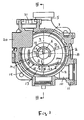
- the centrifugal pump according to the invention is advantageously used in heating and cooling circuits and has a pump chamber 1 with a surrounding housing 2 which can be fastened with a side surface 3 to an electric motor which drives the (not shown) arranged in the pump chamber pump impeller via a shaft whose Axis coaxial with the impeller axis 4 is.
- the pump chamber 1 has an upper discharge nozzle 5 and a coaxial central suction opening 6, which lies on the opposite side of the motor at the center of the impeller, so that the impeller takes the liquid from the suction port 6 via its central suction mouth.
- a vent space 7 with an annular coaxial side wall 8 the axial depth T is smaller than its diameter D and which is separated from the pump chamber 1 by a circular wall 9, in the in the middle of the suction port 6 is located.
- the air deposited in the venting space rises in the form of air bubbles upwards into a venting chamber 20, in which a venting valve 21 is contained.
- vent space 7 opens tangentially below the horizontal channel 10 of a suction nozzle 11, which ends in the side wall 8 with an opening (input port 12).
- the sucked through the channel 10 of the intake 11 liquid enters tangentially into the annular vent space 7 at a position at which the venting space forms a flow channel 13.
- a lower portion of the venting chamber 7 is divided by a curved partition wall 13 with preferably constant thickness, which extends at a distance A to the annular side wall 8 and at a distance B to the suction port 6 and secured with its beginning 14a at the upper end of the inlet opening 12 is formed in particular, while the end 14b of the partition wall 14 ends slightly above the center of the venting chamber 7 and thus almost as high as the upper edge of the suction port 6.
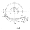
- the partition wall 14 is bent two or more times as follows: In the first area 14a adjoining the inlet opening 12, the lower side surface 15 of the partition 14 bounding the channel 13 is concavely curved, so that the channel 13 in this area I together with the end area of the Channel 10 of the intake manifold 11 has a larger cross-section than in the last third III of the channel 13. In the lying between the areas I and III area II of the second portion 14b of the side surface 15 of the partition wall 14 is wavy shaped with alternating convex and concave areas to the side surface 15 in the region III of the channel 13 merges into a third region 14c, in which the side surface 15 is only convexly shaped.
- the side surface 15 of the partition wall 14 in the second region 14b instead of a wave form also be made substantially straight in particular with arranged transversely to the flow direction surveys in particular corrugations to stimulate the formation of bubbles and their union to large bubbles.
- these elevations can also be arranged in addition to the wavy-shaped side surface 15, in particular in the region I and / or in region II.
- the suction opening 6 is surrounded by a coaxial part-cylindrical wall 16 which covers the entrance area of the opening 6 upwards, so that the liquid emerging from the end of the channel 13 must flow downwards and thus against the upward-aspirating air bubbles to reach the opening 6.
- a vertical wall socket 17 is formed, which further equalizes the flow.
Landscapes
- Engineering & Computer Science (AREA)
- Mechanical Engineering (AREA)
- General Engineering & Computer Science (AREA)
- Life Sciences & Earth Sciences (AREA)
- Sustainable Development (AREA)
- Structures Of Non-Positive Displacement Pumps (AREA)
- Rotary Pumps (AREA)
- Details And Applications Of Rotary Liquid Pumps (AREA)
Abstract
Description
- Die Erfindung betrifft eine Kreiselpumpe mit einem in einem Pumpenraum angeordneten Laufrad und einem dem Pumpenraum vorgeschalteten, eine obere Entlüftungskammer mit Entlüftungsventil aufweisenden Entlüftungsraum, der über eine zentral zum Laufrad angeordnete Ansaugöffnung mit dem Pumpenraum verbunden ist, wobei die zu pumpende Flüssigkeit über einen Ansaugstutzen in den Entlüftungsraum gelangt, dort entlang einer Trennwand strömt, die von dem übrigen Entlüftungsraum einen Strömungskanal abtrennt, der die Ansaugöffnung in einem Abstand bogenförmig umgibt, und im Entlüftungsraum sowie im Strömungskanal die Flüssigkeit Gasblasen insbesondere Luftblasen abgibt, ehe sie in die Ansaugöffnung gelangt.
- Solche Kreiselpumpen sind bekannt und werden in technischen Bereichen eingesetzt, bei denen aus der geförderten Flüssigkeit Gase insbesondere Luft abgeschieden werden müssen.
- Aufgabe der Erfindung ist es, bei einer Pumpe der eingangs genannten Art die Entlüftungsleistung zu erhöhen.
- Diese Aufgabe wird erfindungsgemäß dadurch gelöst, dass der Strömungskanal in seinem an der Öffnung des Ansaugstutzens angrenzenden ersten Bereich einen größeren Strömungsquerschnitt aufweist als im daran anschließenden Kanalbereich.
- Der größere Querschnitt zu Beginn des Strömungskanals führt zu einer Reduzierung der Strömungsgeschwindigkeit und des Druckes und damit zu einer stärkeren Blasenbildung. Es werden vermehrt Blasen gebildet, die im Strömungskanal weitergeführt werden und im Entlüftungsraum hochsteigen zur oberen Entlüftungskammer, wo sie durch das Entlüftungsventil entfernt werden. Die verbesserte Entlüftung bewirkt, dass weniger Gase insbesondere Luft in den Pumpenraum zum Laufrad gelangt, so dass die Geräuschentwicklung verringert ist.
- Konstruktiv besonders einfach wird ein größerer anfänglicher Strömungsraum dadurch erreicht, dass im ersten Bereich des Strömungskanals der der einströmenden Flüssigkeit zugewandte erste Bereich der Seitenfläche der Trennwand konkav gebogen ist. Hierbei kann der konkave Bereich der Trennwand direkt neben der in der Entlüftungsraumwand angeordneten Öffnung des Ansaugstutzens liegen, so dass die in den Entlüftungsraum gelangende Flüssigkeit zuerst auf den konkaven Bereich trifft.
- Vorzugsweise wird vorgeschlagen, dass die die einströmende Flüssigkeit führende Seitenfläche der Trennwand in dem Bereich, der dem ersten konkaven Bereich folgt, konvex gebogen oder im Wesentlichen eben ist. Auch ist besonders vorteilhaft, wenn die Trennwand wellenförmig gebogen ist, so dass hinter dem ersten konkaven Bereich noch mindestens zwei konvexe Bereiche und mindestens ein konkaver Bereich folgt. Durch diese Ausführungen wird die Verweilzeit der Flüssigkeit und der Blasen an der Unterseite der Trennwand verlängert, wodurch die Blasenbildung erleichtert und den Blasen ermöglicht wird, sich zu größeren Blasen zu vereinigen (Koaleszenz), die vermehrt, schneller und sicherer zur Entlüftungskammer und zum Entlüftungsventil gelangen.
- Ein Ausführungsbeispiel der Erfindung ist in den Zeichnungen dargestellt und wird im Folgenden näher beschrieben. Es zeigen
- Fig. 1
- einen Querschnitt durch die Pumpe in Höhe des Entlüftungsraums,
- Fig. 2
- die Trennwand in vergrößerter Darstellung,
- Fig. 3
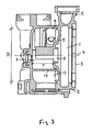
- einen axialen Schnitt nach III-III in
Fig. 1 . - Die erfindungsgemäße Kreiselpumpe ist vorteilhaft in Heizungs- und Kühlkreisläufen einsetzbar und weist einen Pumpenraum 1 auf mit einem umgebenden Gehäuse 2, das mit einer Seitenfläche 3 an einem Elektromotor befestigbar ist, der das im Pumpenraum angeordnete (nicht dargestellte) Pumpenlaufrad über eine Welle antreibt, deren Achse koaxial zur Laufradachse 4 ist. Der Pumpenraum 1 weist einen oberen Druckstutzen 5 und eine koaxiale mittige Ansaugöffnung 6 auf, die auf der dem Motor gegenüberliegenden Seite an der Mitte des Laufrades liegt, so dass das Laufrad über seinen mittigen Saugmund die Flüssigkeit der Ansaugöffnung 6 entnimmt.
- Neben dem Pumpenraum 1 auf der dem Motor abgewandten Seite liegt im Pumpengehäuse 2 ein Entlüftungsraum 7 mit einer ringförmigen koaxialen Seitenwand 8, deren axiale Tiefe T geringer ist als ihr Durchmesser D und die von dem Pumpenraum 1 durch eine kreisförmige Wand 9 getrennt ist, in der mittig die Ansaugöffnung 6 liegt. Die im Entlüftungsraum abgeschiedene Luft steigt in Form von Luftblasen nach oben in eine Entlüftungskammer 20, in der ein Entlüftungsventil 21 enthalten ist.
- In den Entlüftungsraum 7 mündet unten tangential der waagerechte Kanal 10 eines Ansaugstutzens 11, der in der Seitenwand 8 mit einer Öffnung (Eingangsöffnung 12) endet. Die durch den Kanal 10 des Ansaugstutzens 11 angesaugte Flüssigkeit tritt damit tangential in den ringförmigen Entlüftungsraum 7 an einer Stelle ein, an der der Entlüftungsraum einen Strömungskanal 13 bildet. Hierzu ist ein unterer Bereich des Entlüftungsraumes 7 durch eine gebogene Trennwand 13 mit vorzugsweise gleich bleibender Dicke abgeteilt, die in einem Abstand A zur ringförmigen Seitenwand 8 und in einem Abstand B zur Ansaugöffnung 6 verläuft und mit ihrem Anfang 14a am oberen Ende der Eingangsöffnung 12 befestigt insbesondere angeformt ist, während das Ende 14b der Trennwand 14 etwas oberhalb der Mitte des Entlüftungsraums 7 endet und damit fast so hoch reicht wie der obere Rand der Ansaugöffnung 6.
- Die Trennwand 14 ist zwei oder mehrfach wie folgt gebogen: In dem an die Eingangsöffnung 12 angrenzenden ersten Bereich 14a ist die den Kanal 13 begrenzende untere Seitenfläche 15 der Trennwand 14 konkav gewölbt, so dass der Kanal 13 in diesem Bereich I zusammen mit dem Endbereich des Kanals 10 des Ansaugstutzens 11 einen größeren Querschnitt aufweist als in dem letzten Drittel III des Kanals 13. In dem zwischen den Bereichen I und III liegenden Bereich II ist der zweite Bereich 14b der Seitenfläche 15 der Trennwand 14 wellenförmig gestaltet mit abwechselnd konvexen und konkaven Bereichen bis die Seitenfläche 15 im Bereich III des Kanals 13 in einen dritten Bereich 14c übergeht, in dem die Seitenfläche 15 nur noch konvex geformt ist.
- Durch das vergrößerte Volumen im Eintrittsbereich unterhalb der Trennwand kommt es zu einer Verzögerung der Wasser/Luft-Strömung und zu einer Trennung des Gases von der Flüssigkeit, da sich die Luftblasen an der Trennwand ansammeln und sich vereinigen (Koaleszenz). Dieser physikalische Effekt wird noch durch die wellenförmige Gestaltung der Trennwand verbessert. Das sich durch die Vereinigung von Blasen vergrößerte Blasenvolumen führt dazu, dass aufgrund von Trägheitskräften die vergrößerten Blasen von der Flüssigkeitsströmung mitgerissen werden und mit einer verstärkten Auftriebskraft schneller zur Entlüftungskammer gelangen, in der sich das Entlüftungsventil befindet.
- Alternativ kann die Seitenfläche 15 der Trennwand 14 im zweiten Bereich 14b statt einer Wellenform auch im Wesentlichen gerade ausgeführt sein insbesondere mit quer zur Strömungsrichtung angeordneten Erhebungen insbesondere Riffelungen, um die Blasenbildung und deren Vereinigung zu großen Blasen anzuregen. Diese Erhebungen können aber auch zusätzlich an der wellenförmig gestalteten Seitenfläche 15 insbesondere im Bereich I und/oder im Bereich II angeordnet sein.
- Die Ansaugöffnung 6 ist von einer koaxialen teilzylindrischen Wand 16 umgeben, die den Eingangsbereich der Öffnung 6 nach oben abdeckt, so dass die aus dem Ende des Kanals 13 austretende Flüssigkeit nach unten fließen muss und damit entgegen der nach oben strebenden Luftblasen, um die Öffnung 6 zu erreichen. Innerhalb der gebogenen Wand 16 ist noch ein senkrechter Wandstutzen 17 angeformt, der die Strömung weiter vergleichmäßigt.
Claims (5)
- Kreiselpumpe mit einem in einem Pumpenraum (1) angeordneten Laufrad und einem dem Pumpenraum vorgeschalteten, eine obere Entlüftungskammer (20) mit Entlüftungsventil (1) aufweisenden Entlüftungsraum (7), der über eine zentral zum Laufrad angeordnete Ansaugöffnung (6) mit dem Pumpenraum (1) verbunden ist, wobei die zu pumpende Flüssigkeit über einen Ansaugstutzen (11) in den Entlüftungsraum (7) gelangt, dort entlang einer Trennwand (14) strömt, die von dem übrigen Entlüftungsraum einen Strömungskanal (13) abtrennt, der die Ansaugöffnung (6) in einem Abstand bogenförmig umgibt, und im Entlüftungsraum sowie im Strömungskanal die Flüssigkeit Gasblasen insbesondere Luftblasen abgibt, ehe sie in die Ansaugöffnung (6) gelangt, dadurch gekennzeichnet, dass der Strömungskanal (13) in seinem an der Öffnung (12) des Ansaugstutzens (11) angrenzenden ersten Bereich einen größeren Strömungsquerschnitt aufweist als im daran anschließenden Kanalbereich.
- Kreiselpumpe nach Anspruch 1 dadurch gekennzeichnet, dass im ersten Bereich (I) des Strömungskanals (13) die der einströmenden Flüssigkeit zugewandte erste Bereich (14a) der Seitenfläche (15) der Trennwand (14) konkav gebogen ist.
- Kreiselpumpe nach Anspruch 2, dadurch gekennzeichnet, dass der konkave Bereich (14a) der Trennwand (14) direkt neben der in der Entlüftungsraumwand (8) angeordneten Öffnung (12) des Ansaugstutzens (11) liegt, so dass die in den Entlüftungsraum (7) gelangende Flüssigkeit zuerst auf den konkaven Bereich (14a) trifft.
- Kreiselpumpe nach Anspruch 2 oder 3, dadurch gekennzeichnet, dass die die einströmende Flüssigkeit führende Seitenfläche (25) der Trennwand (14) in dem Bereich (14b), der dem ersten konkaven Bereich (14a) folgt, konvex gebogen oder im Wesentlichen eben ist.
- Kreiselpumpe nach einem der vorherigen Ansprüche, dadurch gekennzeichnet, dass die Trennwand (14) wellenförmig gebogen ist, so dass hinter dem ersten konkaven Bereich (14a) noch mindestens zwei konvexe Bereiche und mindestens ein konkaver Bereich folgt.
Priority Applications (3)
| Application Number | Priority Date | Filing Date | Title |
|---|---|---|---|
| AT09006658T ATE507393T1 (de) | 2009-05-18 | 2009-05-18 | Kreiselpumpe mit entlüftungsraum |
| DE502009000603T DE502009000603D1 (de) | 2009-05-18 | 2009-05-18 | Kreiselpumpe mit Entlüftungsraum |
| EP09006658A EP2253850B1 (de) | 2009-05-18 | 2009-05-18 | Kreiselpumpe mit Entlüftungsraum |
Applications Claiming Priority (1)
| Application Number | Priority Date | Filing Date | Title |
|---|---|---|---|
| EP09006658A EP2253850B1 (de) | 2009-05-18 | 2009-05-18 | Kreiselpumpe mit Entlüftungsraum |
Publications (2)
| Publication Number | Publication Date |
|---|---|
| EP2253850A1 true EP2253850A1 (de) | 2010-11-24 |
| EP2253850B1 EP2253850B1 (de) | 2011-04-27 |
Family
ID=41119937
Family Applications (1)
| Application Number | Title | Priority Date | Filing Date |
|---|---|---|---|
| EP09006658A Active EP2253850B1 (de) | 2009-05-18 | 2009-05-18 | Kreiselpumpe mit Entlüftungsraum |
Country Status (3)
| Country | Link |
|---|---|
| EP (1) | EP2253850B1 (de) |
| AT (1) | ATE507393T1 (de) |
| DE (1) | DE502009000603D1 (de) |
Cited By (3)
| Publication number | Priority date | Publication date | Assignee | Title |
|---|---|---|---|---|
| CN108138801A (zh) * | 2015-10-26 | 2018-06-08 | (株)庆东Navien | 锅炉泵 |
| KR20210109796A (ko) * | 2020-02-28 | 2021-09-07 | 엘지전자 주식회사 | 유체 순환 펌프용 가스 분리구 |
| KR20210110060A (ko) * | 2020-02-28 | 2021-09-07 | 엘지전자 주식회사 | 펌프 |
Citations (3)
| Publication number | Priority date | Publication date | Assignee | Title |
|---|---|---|---|---|
| DE3109918A1 (de) * | 1981-03-14 | 1982-10-28 | Wilo-Werk Gmbh & Co Pumpen- Und Apparatebau, 4600 Dortmund | Fluessigkeitspumpe mit gasabscheidekammer |
| GB2192571A (en) * | 1986-07-08 | 1988-01-20 | Grundfos Int | Pump and gas separator set |
| DE29718285U1 (de) | 1997-10-15 | 1997-12-11 | Grundfos A/S, Bjerringbro | Umwälzkreiselpumpe mit Entlüftungseinrichtung |
-
2009
- 2009-05-18 AT AT09006658T patent/ATE507393T1/de active
- 2009-05-18 EP EP09006658A patent/EP2253850B1/de active Active
- 2009-05-18 DE DE502009000603T patent/DE502009000603D1/de active Active
Patent Citations (3)
| Publication number | Priority date | Publication date | Assignee | Title |
|---|---|---|---|---|
| DE3109918A1 (de) * | 1981-03-14 | 1982-10-28 | Wilo-Werk Gmbh & Co Pumpen- Und Apparatebau, 4600 Dortmund | Fluessigkeitspumpe mit gasabscheidekammer |
| GB2192571A (en) * | 1986-07-08 | 1988-01-20 | Grundfos Int | Pump and gas separator set |
| DE29718285U1 (de) | 1997-10-15 | 1997-12-11 | Grundfos A/S, Bjerringbro | Umwälzkreiselpumpe mit Entlüftungseinrichtung |
Cited By (7)
| Publication number | Priority date | Publication date | Assignee | Title |
|---|---|---|---|---|
| CN108138801A (zh) * | 2015-10-26 | 2018-06-08 | (株)庆东Navien | 锅炉泵 |
| EP3369940A4 (de) * | 2015-10-26 | 2019-06-12 | Kyungdong Navien Co., Ltd. | Kesselpumpe |
| KR20210109796A (ko) * | 2020-02-28 | 2021-09-07 | 엘지전자 주식회사 | 유체 순환 펌프용 가스 분리구 |
| KR20210110060A (ko) * | 2020-02-28 | 2021-09-07 | 엘지전자 주식회사 | 펌프 |
| KR102798841B1 (ko) | 2020-02-28 | 2025-04-22 | 엘지전자 주식회사 | 유체 순환 펌프용 가스 분리구 |
| KR102828707B1 (ko) | 2020-02-28 | 2025-07-03 | 엘지전자 주식회사 | 펌프 |
| US12366254B2 (en) | 2020-02-28 | 2025-07-22 | Lg Electronics Inc. | Pump with suction chamber impact body |
Also Published As
| Publication number | Publication date |
|---|---|
| DE502009000603D1 (de) | 2011-06-09 |
| ATE507393T1 (de) | 2011-05-15 |
| EP2253850B1 (de) | 2011-04-27 |
Similar Documents
| Publication | Publication Date | Title |
|---|---|---|
| WO2014187648A1 (de) | Mehrstufiges selbstansaugendes kreiselpumpenaggregat | |
| EP2505842A1 (de) | Mehrstufiges Kreiselpumpenaggregat | |
| EP1417110B1 (de) | Fördereinheit zur anordnung in einem schwalltopf eines kraftstoffbehälters eines kraftfahrzeuges | |
| DE102005031420A1 (de) | Kombinierte Tauch-/Flachabsaug-Rotationspumpe | |
| DE19855433B4 (de) | Saugstrahlpumpe | |
| EP2253850B1 (de) | Kreiselpumpe mit Entlüftungsraum | |
| WO2001081767A1 (de) | Förderpumpe | |
| EP3334942A1 (de) | Dunstabzugsvorrichtung mit diagonalventilator | |
| DE102010052425A1 (de) | Kreiselpumpe | |
| DE102014115286A1 (de) | Abzugsvorrichtung, insbesondere Dunstabzugsvorrichtung | |
| EP1496240A2 (de) | Abscheidesystem | |
| WO2011101121A1 (de) | Dosierpumpe | |
| DE202016102277U1 (de) | Dunstabzugsvorrichtung mit Diagonalventilator | |
| US3204562A (en) | Anti gas-lock construction for turbine pump | |
| EP2072823B1 (de) | Kreiselpumpe mit Entlüftung | |
| EP2423496A1 (de) | Zyklonabscheider mit horizontaler Zyklonachse | |
| EP1024292B1 (de) | Kreiselpumpe mit Gasabscheidekammer | |
| DE102015007100A1 (de) | Selbstansaugende Pumpenaggregation | |
| EP1873399B1 (de) | Kreiselpumpenaggregat | |
| EP1131560A1 (de) | Seitenkanalpumpe | |
| DE1528895C3 (de) | Zentrifugalpumpe | |
| DE102007003555B4 (de) | Förderpumpe mit Filter | |
| DE102012203105B3 (de) | Turboverdichter | |
| EP1423613B1 (de) | Förderpumpe | |
| EP2845635A1 (de) | Entlüfter |
Legal Events
| Date | Code | Title | Description |
|---|---|---|---|
| PUAI | Public reference made under article 153(3) epc to a published international application that has entered the european phase |
Free format text: ORIGINAL CODE: 0009012 |
|
| 17P | Request for examination filed |
Effective date: 20100224 |
|
| AK | Designated contracting states |
Kind code of ref document: A1 Designated state(s): AT BE BG CH CY CZ DE DK EE ES FI FR GB GR HR HU IE IS IT LI LT LU LV MC MK MT NL NO PL PT RO SE SI SK TR |
|
| AX | Request for extension of the european patent |
Extension state: AL BA RS |
|
| GRAP | Despatch of communication of intention to grant a patent |
Free format text: ORIGINAL CODE: EPIDOSNIGR1 |
|
| GRAS | Grant fee paid |
Free format text: ORIGINAL CODE: EPIDOSNIGR3 |
|
| GRAA | (expected) grant |
Free format text: ORIGINAL CODE: 0009210 |
|
| AK | Designated contracting states |
Kind code of ref document: B1 Designated state(s): AT BE BG CH CY CZ DE DK EE ES FI FR GB GR HR HU IE IS IT LI LT LU LV MC MK MT NL NO PL PT RO SE SI SK TR |
|
| REG | Reference to a national code |
Ref country code: GB Ref legal event code: FG4D Free format text: NOT ENGLISH |
|
| REG | Reference to a national code |
Ref country code: CH Ref legal event code: EP |
|
| REG | Reference to a national code |
Ref country code: IE Ref legal event code: FG4D Free format text: LANGUAGE OF EP DOCUMENT: GERMAN |
|
| REF | Corresponds to: |
Ref document number: 502009000603 Country of ref document: DE Date of ref document: 20110609 Kind code of ref document: P |
|
| REG | Reference to a national code |
Ref country code: DE Ref legal event code: R096 Ref document number: 502009000603 Country of ref document: DE Effective date: 20110609 |
|
| REG | Reference to a national code |
Ref country code: NL Ref legal event code: VDEP Effective date: 20110427 |
|
| LTIE | Lt: invalidation of european patent or patent extension |
Effective date: 20110427 |
|
| PG25 | Lapsed in a contracting state [announced via postgrant information from national office to epo] |
Ref country code: NO Free format text: LAPSE BECAUSE OF FAILURE TO SUBMIT A TRANSLATION OF THE DESCRIPTION OR TO PAY THE FEE WITHIN THE PRESCRIBED TIME-LIMIT Effective date: 20110727 Ref country code: HR Free format text: LAPSE BECAUSE OF FAILURE TO SUBMIT A TRANSLATION OF THE DESCRIPTION OR TO PAY THE FEE WITHIN THE PRESCRIBED TIME-LIMIT Effective date: 20110427 Ref country code: PT Free format text: LAPSE BECAUSE OF FAILURE TO SUBMIT A TRANSLATION OF THE DESCRIPTION OR TO PAY THE FEE WITHIN THE PRESCRIBED TIME-LIMIT Effective date: 20110829 Ref country code: SE Free format text: LAPSE BECAUSE OF FAILURE TO SUBMIT A TRANSLATION OF THE DESCRIPTION OR TO PAY THE FEE WITHIN THE PRESCRIBED TIME-LIMIT Effective date: 20110427 Ref country code: LT Free format text: LAPSE BECAUSE OF FAILURE TO SUBMIT A TRANSLATION OF THE DESCRIPTION OR TO PAY THE FEE WITHIN THE PRESCRIBED TIME-LIMIT Effective date: 20110427 |
|
| REG | Reference to a national code |
Ref country code: IE Ref legal event code: FD4D |
|
| BERE | Be: lapsed |
Owner name: WILO SE Effective date: 20110531 |
|
| PG25 | Lapsed in a contracting state [announced via postgrant information from national office to epo] |
Ref country code: IS Free format text: LAPSE BECAUSE OF FAILURE TO SUBMIT A TRANSLATION OF THE DESCRIPTION OR TO PAY THE FEE WITHIN THE PRESCRIBED TIME-LIMIT Effective date: 20110827 Ref country code: LV Free format text: LAPSE BECAUSE OF FAILURE TO SUBMIT A TRANSLATION OF THE DESCRIPTION OR TO PAY THE FEE WITHIN THE PRESCRIBED TIME-LIMIT Effective date: 20110427 Ref country code: SI Free format text: LAPSE BECAUSE OF FAILURE TO SUBMIT A TRANSLATION OF THE DESCRIPTION OR TO PAY THE FEE WITHIN THE PRESCRIBED TIME-LIMIT Effective date: 20110427 Ref country code: CY Free format text: LAPSE BECAUSE OF FAILURE TO SUBMIT A TRANSLATION OF THE DESCRIPTION OR TO PAY THE FEE WITHIN THE PRESCRIBED TIME-LIMIT Effective date: 20110427 Ref country code: GR Free format text: LAPSE BECAUSE OF FAILURE TO SUBMIT A TRANSLATION OF THE DESCRIPTION OR TO PAY THE FEE WITHIN THE PRESCRIBED TIME-LIMIT Effective date: 20110728 Ref country code: ES Free format text: LAPSE BECAUSE OF FAILURE TO SUBMIT A TRANSLATION OF THE DESCRIPTION OR TO PAY THE FEE WITHIN THE PRESCRIBED TIME-LIMIT Effective date: 20110807 Ref country code: FI Free format text: LAPSE BECAUSE OF FAILURE TO SUBMIT A TRANSLATION OF THE DESCRIPTION OR TO PAY THE FEE WITHIN THE PRESCRIBED TIME-LIMIT Effective date: 20110427 |
|
| PG25 | Lapsed in a contracting state [announced via postgrant information from national office to epo] |
Ref country code: NL Free format text: LAPSE BECAUSE OF FAILURE TO SUBMIT A TRANSLATION OF THE DESCRIPTION OR TO PAY THE FEE WITHIN THE PRESCRIBED TIME-LIMIT Effective date: 20110427 Ref country code: MC Free format text: LAPSE BECAUSE OF NON-PAYMENT OF DUE FEES Effective date: 20110531 Ref country code: MT Free format text: LAPSE BECAUSE OF FAILURE TO SUBMIT A TRANSLATION OF THE DESCRIPTION OR TO PAY THE FEE WITHIN THE PRESCRIBED TIME-LIMIT Effective date: 20110427 |
|
| PG25 | Lapsed in a contracting state [announced via postgrant information from national office to epo] |
Ref country code: IE Free format text: LAPSE BECAUSE OF FAILURE TO SUBMIT A TRANSLATION OF THE DESCRIPTION OR TO PAY THE FEE WITHIN THE PRESCRIBED TIME-LIMIT Effective date: 20110427 Ref country code: CZ Free format text: LAPSE BECAUSE OF FAILURE TO SUBMIT A TRANSLATION OF THE DESCRIPTION OR TO PAY THE FEE WITHIN THE PRESCRIBED TIME-LIMIT Effective date: 20110427 Ref country code: EE Free format text: LAPSE BECAUSE OF FAILURE TO SUBMIT A TRANSLATION OF THE DESCRIPTION OR TO PAY THE FEE WITHIN THE PRESCRIBED TIME-LIMIT Effective date: 20110427 |
|
| PG25 | Lapsed in a contracting state [announced via postgrant information from national office to epo] |
Ref country code: PL Free format text: LAPSE BECAUSE OF FAILURE TO SUBMIT A TRANSLATION OF THE DESCRIPTION OR TO PAY THE FEE WITHIN THE PRESCRIBED TIME-LIMIT Effective date: 20110427 Ref country code: RO Free format text: LAPSE BECAUSE OF FAILURE TO SUBMIT A TRANSLATION OF THE DESCRIPTION OR TO PAY THE FEE WITHIN THE PRESCRIBED TIME-LIMIT Effective date: 20110427 Ref country code: SK Free format text: LAPSE BECAUSE OF FAILURE TO SUBMIT A TRANSLATION OF THE DESCRIPTION OR TO PAY THE FEE WITHIN THE PRESCRIBED TIME-LIMIT Effective date: 20110427 Ref country code: DK Free format text: LAPSE BECAUSE OF FAILURE TO SUBMIT A TRANSLATION OF THE DESCRIPTION OR TO PAY THE FEE WITHIN THE PRESCRIBED TIME-LIMIT Effective date: 20110427 |
|
| PLBE | No opposition filed within time limit |
Free format text: ORIGINAL CODE: 0009261 |
|
| STAA | Information on the status of an ep patent application or granted ep patent |
Free format text: STATUS: NO OPPOSITION FILED WITHIN TIME LIMIT |
|
| PG25 | Lapsed in a contracting state [announced via postgrant information from national office to epo] |
Ref country code: BE Free format text: LAPSE BECAUSE OF NON-PAYMENT OF DUE FEES Effective date: 20110531 |
|
| 26N | No opposition filed |
Effective date: 20120130 |
|
| REG | Reference to a national code |
Ref country code: DE Ref legal event code: R097 Ref document number: 502009000603 Country of ref document: DE Effective date: 20120130 |
|
| PG25 | Lapsed in a contracting state [announced via postgrant information from national office to epo] |
Ref country code: MK Free format text: LAPSE BECAUSE OF FAILURE TO SUBMIT A TRANSLATION OF THE DESCRIPTION OR TO PAY THE FEE WITHIN THE PRESCRIBED TIME-LIMIT Effective date: 20110427 |
|
| PG25 | Lapsed in a contracting state [announced via postgrant information from national office to epo] |
Ref country code: LU Free format text: LAPSE BECAUSE OF NON-PAYMENT OF DUE FEES Effective date: 20110518 |
|
| PG25 | Lapsed in a contracting state [announced via postgrant information from national office to epo] |
Ref country code: BG Free format text: LAPSE BECAUSE OF FAILURE TO SUBMIT A TRANSLATION OF THE DESCRIPTION OR TO PAY THE FEE WITHIN THE PRESCRIBED TIME-LIMIT Effective date: 20110727 |
|
| PG25 | Lapsed in a contracting state [announced via postgrant information from national office to epo] |
Ref country code: TR Free format text: LAPSE BECAUSE OF FAILURE TO SUBMIT A TRANSLATION OF THE DESCRIPTION OR TO PAY THE FEE WITHIN THE PRESCRIBED TIME-LIMIT Effective date: 20110427 |
|
| PG25 | Lapsed in a contracting state [announced via postgrant information from national office to epo] |
Ref country code: HU Free format text: LAPSE BECAUSE OF FAILURE TO SUBMIT A TRANSLATION OF THE DESCRIPTION OR TO PAY THE FEE WITHIN THE PRESCRIBED TIME-LIMIT Effective date: 20110427 |
|
| REG | Reference to a national code |
Ref country code: CH Ref legal event code: PL |
|
| PG25 | Lapsed in a contracting state [announced via postgrant information from national office to epo] |
Ref country code: LI Free format text: LAPSE BECAUSE OF NON-PAYMENT OF DUE FEES Effective date: 20130531 Ref country code: CH Free format text: LAPSE BECAUSE OF NON-PAYMENT OF DUE FEES Effective date: 20130531 |
|
| PGFP | Annual fee paid to national office [announced via postgrant information from national office to epo] |
Ref country code: GB Payment date: 20140514 Year of fee payment: 6 |
|
| REG | Reference to a national code |
Ref country code: AT Ref legal event code: MM01 Ref document number: 507393 Country of ref document: AT Kind code of ref document: T Effective date: 20140518 |
|
| PG25 | Lapsed in a contracting state [announced via postgrant information from national office to epo] |
Ref country code: AT Free format text: LAPSE BECAUSE OF NON-PAYMENT OF DUE FEES Effective date: 20140518 |
|
| GBPC | Gb: european patent ceased through non-payment of renewal fee |
Effective date: 20150518 |
|
| REG | Reference to a national code |
Ref country code: FR Ref legal event code: PLFP Year of fee payment: 8 |
|
| PG25 | Lapsed in a contracting state [announced via postgrant information from national office to epo] |
Ref country code: GB Free format text: LAPSE BECAUSE OF NON-PAYMENT OF DUE FEES Effective date: 20150518 |
|
| REG | Reference to a national code |
Ref country code: FR Ref legal event code: PLFP Year of fee payment: 9 |
|
| REG | Reference to a national code |
Ref country code: FR Ref legal event code: PLFP Year of fee payment: 10 |
|
| PGFP | Annual fee paid to national office [announced via postgrant information from national office to epo] |
Ref country code: IT Payment date: 20220421 Year of fee payment: 14 |
|
| P01 | Opt-out of the competence of the unified patent court (upc) registered |
Effective date: 20230615 |
|
| PGFP | Annual fee paid to national office [announced via postgrant information from national office to epo] |
Ref country code: FR Payment date: 20230420 Year of fee payment: 15 |
|
| REG | Reference to a national code |
Ref country code: DE Ref legal event code: R084 Ref document number: 502009000603 Country of ref document: DE |
|
| PG25 | Lapsed in a contracting state [announced via postgrant information from national office to epo] |
Ref country code: IT Free format text: LAPSE BECAUSE OF NON-PAYMENT OF DUE FEES Effective date: 20230518 |
|
| PG25 | Lapsed in a contracting state [announced via postgrant information from national office to epo] |
Ref country code: FR Free format text: LAPSE BECAUSE OF NON-PAYMENT OF DUE FEES Effective date: 20240531 |
|
| PGFP | Annual fee paid to national office [announced via postgrant information from national office to epo] |
Ref country code: DE Payment date: 20250423 Year of fee payment: 17 |