EP2253531A1 - Electrical bicycle shift control device - Google Patents
Electrical bicycle shift control device Download PDFInfo
- Publication number
- EP2253531A1 EP2253531A1 EP09170888A EP09170888A EP2253531A1 EP 2253531 A1 EP2253531 A1 EP 2253531A1 EP 09170888 A EP09170888 A EP 09170888A EP 09170888 A EP09170888 A EP 09170888A EP 2253531 A1 EP2253531 A1 EP 2253531A1
- Authority
- EP
- European Patent Office
- Prior art keywords
- shift operating
- shift
- operating member
- control device
- electrical
- Prior art date
- Legal status (The legal status is an assumption and is not a legal conclusion. Google has not performed a legal analysis and makes no representation as to the accuracy of the status listed.)
- Granted
Links
- 244000309464 bull Species 0.000 description 7
- 230000000994 depressogenic effect Effects 0.000 description 7
- 239000000463 material Substances 0.000 description 4
- 230000006835 compression Effects 0.000 description 2
- 238000007906 compression Methods 0.000 description 2
- 239000004020 conductor Substances 0.000 description 2
- 238000013459 approach Methods 0.000 description 1
- 230000002860 competitive effect Effects 0.000 description 1
- 238000010276 construction Methods 0.000 description 1
- 230000007423 decrease Effects 0.000 description 1
- 230000009977 dual effect Effects 0.000 description 1
- 210000000245 forearm Anatomy 0.000 description 1
- 238000012986 modification Methods 0.000 description 1
- 230000004048 modification Effects 0.000 description 1
- 230000004043 responsiveness Effects 0.000 description 1
Images


Classifications
-
- B—PERFORMING OPERATIONS; TRANSPORTING
- B62—LAND VEHICLES FOR TRAVELLING OTHERWISE THAN ON RAILS
- B62M—RIDER PROPULSION OF WHEELED VEHICLES OR SLEDGES; POWERED PROPULSION OF SLEDGES OR SINGLE-TRACK CYCLES; TRANSMISSIONS SPECIALLY ADAPTED FOR SUCH VEHICLES
- B62M25/00—Actuators for gearing speed-change mechanisms specially adapted for cycles
- B62M25/02—Actuators for gearing speed-change mechanisms specially adapted for cycles with mechanical transmitting systems, e.g. cables, levers
- B62M25/04—Actuators for gearing speed-change mechanisms specially adapted for cycles with mechanical transmitting systems, e.g. cables, levers hand actuated
-
- B—PERFORMING OPERATIONS; TRANSPORTING
- B62—LAND VEHICLES FOR TRAVELLING OTHERWISE THAN ON RAILS
- B62K—CYCLES; CYCLE FRAMES; CYCLE STEERING DEVICES; RIDER-OPERATED TERMINAL CONTROLS SPECIALLY ADAPTED FOR CYCLES; CYCLE AXLE SUSPENSIONS; CYCLE SIDE-CARS, FORECARS, OR THE LIKE
- B62K23/00—Rider-operated controls specially adapted for cycles, i.e. means for initiating control operations, e.g. levers, grips
- B62K23/02—Rider-operated controls specially adapted for cycles, i.e. means for initiating control operations, e.g. levers, grips hand actuated
- B62K23/06—Levers
-
- B—PERFORMING OPERATIONS; TRANSPORTING
- B62—LAND VEHICLES FOR TRAVELLING OTHERWISE THAN ON RAILS
- B62M—RIDER PROPULSION OF WHEELED VEHICLES OR SLEDGES; POWERED PROPULSION OF SLEDGES OR SINGLE-TRACK CYCLES; TRANSMISSIONS SPECIALLY ADAPTED FOR SUCH VEHICLES
- B62M25/00—Actuators for gearing speed-change mechanisms specially adapted for cycles
- B62M25/08—Actuators for gearing speed-change mechanisms specially adapted for cycles with electrical or fluid transmitting systems
-
- Y—GENERAL TAGGING OF NEW TECHNOLOGICAL DEVELOPMENTS; GENERAL TAGGING OF CROSS-SECTIONAL TECHNOLOGIES SPANNING OVER SEVERAL SECTIONS OF THE IPC; TECHNICAL SUBJECTS COVERED BY FORMER USPC CROSS-REFERENCE ART COLLECTIONS [XRACs] AND DIGESTS
- Y10—TECHNICAL SUBJECTS COVERED BY FORMER USPC
- Y10T—TECHNICAL SUBJECTS COVERED BY FORMER US CLASSIFICATION
- Y10T74/00—Machine element or mechanism
- Y10T74/20—Control lever and linkage systems
- Y10T74/20012—Multiple controlled elements
- Y10T74/20018—Transmission control
- Y10T74/2003—Electrical actuator
-
- Y—GENERAL TAGGING OF NEW TECHNOLOGICAL DEVELOPMENTS; GENERAL TAGGING OF CROSS-SECTIONAL TECHNOLOGIES SPANNING OVER SEVERAL SECTIONS OF THE IPC; TECHNICAL SUBJECTS COVERED BY FORMER USPC CROSS-REFERENCE ART COLLECTIONS [XRACs] AND DIGESTS
- Y10—TECHNICAL SUBJECTS COVERED BY FORMER USPC
- Y10T—TECHNICAL SUBJECTS COVERED BY FORMER US CLASSIFICATION
- Y10T74/00—Machine element or mechanism
- Y10T74/20—Control lever and linkage systems
- Y10T74/20012—Multiple controlled elements
- Y10T74/20018—Transmission control
- Y10T74/20037—Occupant propelled vehicle
-
- Y—GENERAL TAGGING OF NEW TECHNOLOGICAL DEVELOPMENTS; GENERAL TAGGING OF CROSS-SECTIONAL TECHNOLOGIES SPANNING OVER SEVERAL SECTIONS OF THE IPC; TECHNICAL SUBJECTS COVERED BY FORMER USPC CROSS-REFERENCE ART COLLECTIONS [XRACs] AND DIGESTS
- Y10—TECHNICAL SUBJECTS COVERED BY FORMER USPC
- Y10T—TECHNICAL SUBJECTS COVERED BY FORMER US CLASSIFICATION
- Y10T74/00—Machine element or mechanism
- Y10T74/20—Control lever and linkage systems
- Y10T74/20012—Multiple controlled elements
- Y10T74/20018—Transmission control
- Y10T74/2014—Manually operated selector [e.g., remotely controlled device, lever, push button, rotary dial, etc.]
- Y10T74/20159—Control lever movable through plural planes
-
- Y—GENERAL TAGGING OF NEW TECHNOLOGICAL DEVELOPMENTS; GENERAL TAGGING OF CROSS-SECTIONAL TECHNOLOGIES SPANNING OVER SEVERAL SECTIONS OF THE IPC; TECHNICAL SUBJECTS COVERED BY FORMER USPC CROSS-REFERENCE ART COLLECTIONS [XRACs] AND DIGESTS
- Y10—TECHNICAL SUBJECTS COVERED BY FORMER USPC
- Y10T—TECHNICAL SUBJECTS COVERED BY FORMER US CLASSIFICATION
- Y10T74/00—Machine element or mechanism
- Y10T74/20—Control lever and linkage systems
- Y10T74/20576—Elements
- Y10T74/20582—Levers
- Y10T74/20612—Hand
- Y10T74/20618—Jointed
Definitions
- the first lever body part 70 is a one-piece, unitary member that has a first pivot hole 70a, a first mounting recess 70b, a first pivot bore 70c and a first cutout 70d.
- One end of the pivot pin 24 is received in the first pivot hole 70a to pivotally support the first lever body part 70.
- One of the mounting flange parts 42b of the friction member 42 is received in the first mounting recess 70b to fixedly support the friction member 42 on the first lever body part 70 so that the friction member 42 moves with the first lever body part 70 with respect to the base member 20.
- the first pivot bore 70c is a blind bore that pivotally supports the second shift operating member 22 on the first lever body part 70.
- the first cutout 70d forms a first part of an opening for the second shift operating member 22 such that the second shift operating member 22 partially projects out of the top surface of the first shift operating member 21.
- the second shift operating member 22 is moved in the second shift operating direction D2 to perform a shifting operation, the coil springs 84 and 86 are compressed.
- the second electrical switch 32 is operated (closed).
- the second shift operating member 22 is moved in the second shift operating direction D2 to perform a shifting operation, only the shift signal of the second electrical switch 32 will be output to the derailleur.
- the second electrical switch 32 is illustrated as a normally open switch, it will be apparent from this disclosure that it can be a normally closed switch.
Abstract
Description
- This invention generally relates to a bicycle control device for performing a shifting operation. More specifically, the present invention relates to a electric bar end shifter which is configured to be mounted to a free end of a bicycle handlebar in an integrated manner.
- Bicycling is becoming an increasingly more popular form of recreation as well as a means of transportation. Moreover, bicycling has become a very popular competitive sport for both amateurs and professionals. Whether the bicycle is used for recreation, transportation or competition, the bicycle industry is constantly improving the various components of the bicycle, especially the bicycle control devices for shifting and braking.
- In the case of a time trial bicycle, a bull horn handlebar is often used that curve forward away from the rider that allows the rider to ride in a tuck position. The bull horn handlebar is sometimes provided with a pair of aero bars or a single loop shaped aero bar. The aero bar attaches to the main bar near the stem and provides a position where the hands and fore-arms are close together, low and forward, providing a very aerodynamic (though less stable) position. Typically, each end of the bull horn handlebar is provided with a "handlebar-end shifter" or "bar-end shifter". These bar-end shifters can include a brake lever in some instances. Recently, bar-end shifters have been added to the free ends of aero bars of the cantilevered type.
- In the past, bar-end shifters were mechanically operated devices that were sometimes located near the brake levers of the bicycle. Thus, an operating force was typically applied by one of the rider's fingers to operate a shift control lever, which in turn transmitted the operating force to the drive component of a bicycle shifting mechanism by a cable that was fixed at one end to the control lever. More recently, electric switches have been used instead of mechanical control levers in order to operate the bicycle shifting mechanism. One example of an electrical shift control device is disclosed in
U.S. Patent No. 5,358,451 . This patent discloses a plurality of electric switches may be provided at a plurality of handlebar locations in order to allow for quicker shifts and to enhance responsiveness. Another example of a bicycle electrical shift control device is disclosed inU.S. Patent Application Publication No. 2005/0211014 . - One object of the present invention is to provide an electric bar end shifter having two electrical shift switches that can be easily operated.
- The foregoing object can basically be attained by providing an electrical bicycle shift control device comprising a base member, a first shift operating member and a second shift operating member. The handlebar mounting portion is configured to be fixedly mounted to a free end of a bicycle handlebar. The base member includes a handlebar mounting portion that is configured to be fixedly mounted a handlebar. The first shift operating member is pivotally coupled the base member from a rest position to a shift position in a first shift operating direction. The second shift operating member is mounted on the first shift operating member to move with the first shift operating member with respect to the base member. The second shift operating member is independently movable relative the first shift operating member from a rest position to a shift position in a second shift operating direction that is different to the first shift operating direction.
- This and other objects, features, aspects and advantages of the present invention will become apparent to those skilled in the art from the following detailed description, which, taken in conjunction with the annexed drawings, discloses preferred embodiments.
- Referring now to the attached drawings which form a part of this original disclosure:
-
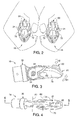
Figure 1 is a partial front perspective view of a bicycle equipped with a pair of aero bars with a pair of middle electric bar end shifters (shift control devices) mounted to the free ends of the aero bars in accordance with a first embodiment; -
Figure 2 is a front elevational view of the bar end shifters, with a rider gripping the aero bars; -
Figure 3 is a side elevational view of the right bar end shifter illustrated inFigures 1 and2 , prior to attachment to the free end of the right side aero bar; -
Figure 4 is a top plan view of the right bar end shifter illustrated inFigures 1 to 3 , prior to attachment to the free end of the right side aero bar; -
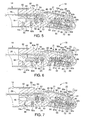
Figure 5 is a cross-sectional view of the right bar end shifter as seen along section line 5-5 ofFigure 4 , but with the right bar end shifter attached to the free end of the right side aero bar and the first and second shift operating members in rest positions; -
Figure 6 is a cross-sectional view, similar toFigure 5 , of the right bar end shifter attached to the free end of the right side aero bar with the first shift operating member in the shift position and the second shift operating member in the rest position; -
Figure 7 is a cross-sectional view, similar toFigure 5 , of the right bar end shifter attached to the free end of the right side aero bar with the first shift operating member in the rest position and the second shift operating member in the shift position; -
Figure 8 is an exploded perspective view of the right bar end shifter illustrated inFigures 1 to 7 with the cover exploded outwardly to reveal the internal shifting components; -
Figure 9 is another exploded perspective view of the right bar end shifter illustrated inFigures 1 to 8 with the cover exploded outwardly to reveal the internal shifting components; -
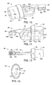
Figure 10 is a perspective view of the base member of the right bar end shifter illustrated inFigures 1 to 9 ; -
Figure 11 is a side elevational view of the base member illustrated inFigure 10 for the right bar end shifter illustrated inFigures 1 to 9 ; -
Figure 12 is a bottom plan view of the base member illustrated inFigure 10 and 11 for the right bar end shifter illustrated inFigures 1 to 9 ; -
Figure 13 is a rear end elevational view of the base member illustrated inFigures 10 to 12 for the right bar end shifter illustrated inFigures 1 to 9 ; -
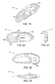
Figure 14 is a perspective view of the first lever body part of the first shift operating member for the right bar end shifter illustrated inFigures 1 to 9 ; -
Figure 15 is an outside elevational view of the first lever body part of the first shift operating member illustrated inFigure 14 for the right bar end shifter illustrated inFigures 1 to 9 ; -
Figure 16 is an inside elevational view of the first lever body part of the first shift operating member illustrated inFigures 14 and 15 for the right bar end shifter illustrated inFigures 1 to 9 ; -
Figure 17 is a front end elevational view of the first lever body part of the first shift operating member illustrated inFigures 14 to 16 for the right bar end shifter illustrated inFigures 1 to 9 ; -
Figure 18 is a bottom plan view of the first lever body part of the first shift operating member illustrated inFigures 14 to 17 for the right bar end shifter illustrated inFigures 1 to 9 ; -
Figure 19 is a perspective view of the second lever body part of the first shift operating member for the right bar end shifter illustrated inFigures 1 to 9 ; -
Figure 20 is an outside elevational view of the second lever body part of the first shift operating member illustrated inFigure 19 for the right bar end shifter illustrated inFigures 1 to 9 ; -
Figure 21 is an inside elevational view of the second lever body part of the first shift operating member illustrated inFigures 19 and 20 for the right bar end shifter illustrated inFigures 1 to 9 ; -
Figure 22 is a front end elevational view of the second lever body part of the first shift operating member illustrated inFigures 19 to 21 for the right bar end shifter illustrated inFigures 1 to 9 ; -
Figure 23 is a bottom plan view of the second lever body part of the first shift operating member illustrated inFigures 19 to 22 for the right bar end shifter illustrated inFigures 1 to 9 ; -
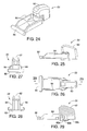
Figure 24 is a perspective view of the second shift operating member for the right bar end shifter illustrated inFigures 1 to 9 ; -
Figure 25 is a side elevational view of the second shift operating member illustrated inFigure 24 for the right bar end shifter illustrated inFigures 1 to 9 ; -
Figure 26 is a top plan view of the second shift operating member illustrated inFigures 24 and 25 for the right bar end shifter illustrated inFigures 1 to 9 ; -
Figure 27 is a rear end elevational view of the second shift operating member illustrated inFigures 24 to 26 for the right bar end shifter illustrated inFigures 1 to 9 ; -
Figure 28 is a front end elevational view of the second shift operating member illustrated inFigures 24 to 27 for the right bar end shifter illustrated inFigures 1 to 9 ; -
Figure 29 is a cross-sectional view of the second shift operating member illustrated inFigures 24 to 28 as seen along section line 29-29 ofFigure 28 ; -
Figure 30 is a perspective view of the friction member for the right bar end shifter illustrated inFigures 1 to 9 ; -
Figure 31 is a side elevational view of the friction member illustrated inFigure 30 for the right bar end shifter illustrated inFigures 1 to 9 ; -
Figure 32 is a rear elevational view of the friction member illustrated inFigures 30 and 31 for the right bar end shifter illustrated inFigures 1 to 9 ; -
Figure 33 is a cross-sectional view of the second shift operating member illustrated inFigures 30 to 32 as seen along section line 33-33 ofFigure 32 ; -
Figure 34 is a front elevational view of a pair of bar end shifters in accordance with a second embodiment, with a rider gripping the aero bars; -
Figure 35 is a side elevational view of the right bar end shifter illustrated inFigure 34 , prior to attachment to the free end of the right side aero bar; and -
Figure 36 is a top plan view of the right bar end shifter illustrated inFigures 34 and 35 , prior to attachment to the free end of the right side aero bar. - Selected embodiments of the present invention will now be explained with reference to the drawings. It will be apparent to those skilled in the art from this disclosure that the following descriptions of the embodiments of the present invention are provided for illustration only and not for the purpose of limiting the invention as defined by the appended claims and their equivalents.
- Referring initially to
Figure 1 , atime trial bicycle 10 is illustrated with abull horn handlebar 12 and a pair ofaero bars 14 with a pair of middle electricbar end shifters 16 in accordance with a first embodiment. Thebar end shifters 16 are mounted to the free ends of the aero bars 14. Thebar end shifters 16 constitute electrical bicycle shift control devices as discussed below. Theaero bars 14 constitute cantilevered handlebars as discussed below. Thebull horn handlebar 12 is also provided with a pair of main electricbar end shifter 18 coupled to free ends of thebull horn handlebar 12. - As seen in
Figures 2 and 3 , thebar end shifters 16 are configured to be operated in a generally vertical plane (shift operating directions D1 and D2) such that thebar end shifters 16 can be position closely together to reduce air resistance. In other words, since the operating directions of thebar end shifters 16 are not operated in a horizontal direction with respect to thebicycle 10, the rider does not need to move his/her hands or fingers in a sideways direction (horizontal plane) to operate thebar end shifters 16. Thus, no additional space is needed between thebar end shifters 16 for operating them. - Basically, each of the
bar end shifters 16 is provided with abase member 20, a firstshift operating member 21 and a secondshift operating member 22. In this illustrated embodiment, thebar end shifters 16 are identical in construction. However, one of thebar end shifters 16 is operatively (electrically) coupled to a rear derailleur (not shown), while the other of thebar end shifters 16 is operatively (electrically) coupled to a front derailleur (not shown). Since derailleurs as well as other conventional bicycle parts of thebicycle 10 are well known in the bicycle art, the derailleurs and the other bicycle parts of thebicycle 10 will not be discussed or illustrated in detail herein, except for the parts relating to the present invention. Moreover, various conventional bicycle parts, which are not illustrated and/or discussed in detail herein, can also be used in conjunction with thebar end shifters 16. - The first
shift operating member 21 is pivotally coupled thebase member 20 by apivot pin 24. In this illustrated embodiment, thepivot pin 24 is formed by abolt 24a and anut 24b. Thepivot pin 24 defines a first pivot axis A1 in which the firstshift operating member 21 pivots about the first pivot axis A1 with respect to thebase member 20. The secondshift operating member 22 is mounted on the firstshift operating member 21 to move with the firstshift operating member 21 with respect to thebase member 20 about the first pivot axis A1 when the firstshift operating member 21 is pivoted from a rest position (Figure 5 ) to a shift or operating position (Figure 6 ) in the first shift operating direction D1 as explained below. The secondshift operating member 22 is also independently movable relative the firstshift operating member 21 about a second pivot axis A2 from a rest position (Figure 5 ) to a shift or operating position (Figure 7 ) in the second shift operating direction D2, which is different to the first shift operating direction D1. In this illustrated embodiment, the first and second pivot axes A1 and A2 are different axes that are parallel (as shown) or substantially parallel (i.e., within five degrees of parallel) to each other. Also in this illustrated embodiment, the second shift operating direction D2 of the secondshift operating member 22 is substantially opposite to the first shift operating direction D1. Since the first and secondshift operating members shift operating members shift operating member 22 is not limited to pivotally movement. - An electrical
shift control unit 26 is mounted with the firstshift operating member 21. Basically, the firstshift operating member 21 supports the electricalshift control unit 26 such that the electricalshift control unit 26 moves (pivots) with the firstshift operating member 21 with respect to thebase member 20 about the first pivot axis A1 when the firstshift operating member 21 is pivoted from a rest position (Figure 5 ) to a shift position (Figure 6 ) in the first shift operating direction D1 as explained below. The electricalshift control unit 26 is electrically coupled to an electric derailleur or some other type of gear shifting device by anelectrical cord 28 having one or more electrical conductors. - As seen in
Figures 5 to 9 , the electricalshift control unit 26 is a waterproof electrical switch unit that basically includes anelectrical switch housing 30, a firstelectrical switch 31, a secondelectrical switch 32 and asingle circuit board 33. Theelectrical switch housing 30 is supported on the firstshift operating member 21. Thus, the first and secondelectrical switches shift operating member 21 for movement with the firstshift operating member 21 relative to thebase member 20. The first and secondelectrical switches single circuit board 33 that is disposed within theelectrical switch housing 30 - One of the first and second
electrical switches electrical switches electrical switches 31 and 32) can be utilized for both upshifting and downshifting one of the derailleurs. The firstelectrical switch 31 is operated by the firstshift operating member 21, and outputs the first shift (control) signal when the firstshift operating member 21 is pivoted from the rest position (Figure 5 ) to the shift position (Figure 6 ) in the first shift operating direction D1. The secondelectrical switch 32 is operated by the secondshift operating member 22, and outputs the second shift (control) signal when the secondshift operating member 22 is pivoted from the rest position (Figure 5 ) to the shift position (Figure 7 ) in the second shift operating direction D2. The firstshift operating member 21 is an upshift member that is rotated upwardly to upshift towards a higher gear, while the secondshift operating member 22 is a downshift member that is depressed downwardly to downshift towards a lower gear. Of course, it will be apparent to those skilled in the art from this disclosure that the upshifting and downshifting operations of the first and secondshift operating members electrical cord 28 are connected to the derailleur. - In the illustrated embodiment, the first and second
electrical switches electrical switch 31 has afirst button 31a that is operated (depressed) by the firstshift operating member 21 when the firstshift operating member 21 is pivoted from the rest position (Figure 5 ) to the shift position (Figure 6 ) in the first shift operating direction D1. Similarly, the secondelectrical switch 32 has asecond button 32a that is operated (depressed) by the secondshift operating member 22 when the secondshift operating member 22 is pivoted from the rest position (Figure 5 ) to the shift position (Figure 7 ) in the second shift operating direction D2. Each of the first and secondelectrical switches button shift operating member electrical switches electrical switches - Preferably, a shift
operation indicating mechanism 40 is installed in thebase member 20 for indicating when the firstshift operating member 21 has been pivoted from the rest position (Figure 5 ) to the shift position (Figure 6 ) in the first shift operating direction D1. In this embodiment, the shiftoperation indicating mechanism 40 provides both a clicking noise and a haptic signal to the rider when the firstshift operating member 21 has been pivoted from the rest position (Figure 5 ) to the shift position (Figure 6 ). - As best seen in
Figures 5 to 9 , the shiftoperation indicating mechanism 40 preferably includes afriction member 42 and adetent 44. The shift operation indicating mechanism increases a load on the firstshift operating member 21 when the firstshift operating member 21 is move in the first shift direction D1 from the rest position (Figure 5 ) of the firstshift operating member 21 to the shift position (Figure 6 ) of the firstshift operating member 21. As best seen inFigures 30 to 33 , thefriction member 42 has acenter part 42a with a pair of mountingflange parts 42b extending laterally from thecenter part 42a. Thecenter part 42a has acurved engagement surface 42c with arecess 42d. Therecess 42d receives thedetent 44 when the firstshift operating member 21 is in the rest position (Figure 5 ). When the firstshift operating member 21 has been pivoted from the rest position (Figure 5 ) to the shift position (Figure 6 ), thedetent 44 engages thecurved engagement surface 42c. The mountingflange parts 42b of thefriction member 42 is attached to the firstshift operating member 21 by the mountingflange parts 42b, while thedetent 44 is attached to thebase member 20. In the illustrated embodiment, thedetent 44 is a bolt that is threaded into ahole 48 in thebase member 20. As best seen inFigure 8 , thedetent 44 has a free tip end with ahemisphere 44a. Thehemisphere 44a is engaged with therecess 42d when the firstshift operating member 21 is in the rest position (Figure 5 ). Thehemisphere 44a engages thecurved engagement surface 42c when the firstshift operating member 21 is in the shift position (Figure 6 ). Since thefriction member 42 is attached to the firstshift operating member 21, therecess 42d is effectively disposed on the firstshift operating member 21. Also since thedetent 44 is attached to thebase member 20, thehemisphere 44a is effectively disposed on thebase member 20. Alternatively, therecess 42d is effectively disposed on thebase member 20, and thehemisphere 44a is effectively disposed on the firstshift operating member 21. In other words, the arrangement of thefriction member 42 and thedetent 44 can be reversed, if needed and/or desired. - As best seen in
Figures 10 to 13 , thebase member 20 is a one-piece, unitary bracket member that is constructed of a hard, rigid material such as a hard, rigid plastic material. Thebase member 20 includes ahandlebar mounting portion 50, anabutment portion 52, apivot portion 54 and anactuation portion 56. As mentioned above, thebase member 20 pivotally supports the firstshift operating member 21, which in turn supports the secondshift operating member 22 and the electricalshift control unit 26. As seen inFigures 5 to 7 , theelectrical cord 28 of the electricalshift control unit 26 extends from theactuation portion 56, through apassageway 58 formed in theportions aero bar 14. - The
handlebar mounting portion 50 of thebase member 20 is configured to be fixedly mounted one of theaero bars 14 such that thebar end shifters 16 is cantilevered with respect to the free end of theaero bar 14. In particular, thehandlebar mounting portion 50 is dimensioned to fit inside the free end of theaero bar 14. In this embodiment, thehandlebar mounting portion 50 is an elliptical column that fits into an elliptical interior of the free end of theaero bar 14. Of course, it will be apparent from this disclosure that the shape of thehandlebar mounting portion 50 depends on the shape of the free end of theaero bar 14. Ahandlebar attachment bolt 60 is used to fix thebase member 20 to the free end of theaero bar 14. Thehandlebar attachment bolt 60 extends through anopening 14a and is threaded into one of a plurality (three) of threadedholes 50a in thehandlebar mounting portion 50. - The
abutment portion 52 of thebase member 20 has a larger cross sectional dimension than thehandlebar mounting portion 50 so as to abut against the free end of theaero bar 14 when thehandlebar mounting portion 50 is fitted inside the free end of theaero bar 14. Theabutment portion 52 of thebase member 20 also has aradially extending hole 52a that threadedly receives astop bolt 62. - The
pivot portion 54 of thebase member 20 is provided with apivot hole 54a and anopening 54b. Thepivot hole 54a receives thepivot pin 24 therethrough for pivotally supporting the firstshift operating member 21 to thepivot portion 54 of thebase member 20. Theopening 54b receives thecenter part 42a of thefriction member 42. Theopening 54b is dimensioned so that thecenter part 42a of thefriction member 42 can move in a vertical plane as the firstshift operating member 21 is pivoted from the rest position (Figure 5 ) to the shift position (Figure 6 ). - The
actuation portion 56 of thebase member 20 is provided with afirst projection 56a, a firsttubular portion 56b and an additionaltubular portion 56c. The firsttubular portion 56b encircles thefirst projection 56a. The additionaltubular portion 56c is located closer to the first pivot axis A1 than the firsttubular portion 56b. The firsttubular portion 56b receives a firstcoil buffer spring 64, while the additionaltubular portion 56c receives a firstcoil return spring 66. - The first
coil buffer spring 64 is provided between theactuation portion 56 of thebase member 20 and theelectrical signal unit 26 to smoothly operate the firstelectrical switch 31 when the firstshift operating member 21 is moved in the first shift operating direction D1. The firstcoil buffer spring 64 constitutes a first operating portion of thebase member 20. In particular, a first end of the firstcoil buffer spring 64 contacts a base of thefirst button 31a with a center projection of thefirst button 31a disposed in the center of the firstcoil buffer spring 64, while a second end of the firstcoil buffer spring 64 is disposed in the firsttubular portion 56b with thefirst projection 56a disposed in the center of the firstcoil buffer spring 64. As the firstshift operating member 21 is moved in the first shift operating direction D1 to perform a shifting operation, the firstcoil buffer spring 64 is compressed. This compression of the firstcoil buffer spring 64 depresses the base of thefirst button 31a of the firstelectrical switch 31 to operate (close) the firstelectrical switch 31 for outputting a shift signal. In other words, when the spring force of the firstcoil buffer spring 64 exceeds a prescribed force, the internal spring of the firstelectrical switch 31 is compressed so that thefirst button 31a of the firstelectrical switch 31 is depressed to close the internal contacts of the firstelectrical switch 31. - The first
coil return spring 66 is provided between theactuation portion 56 of thebase member 20 and theelectrical signal unit 26 to bias the firstshift operating member 21 with respect to thebase member 20 about the first pivot axis A1 in an opposite direction to the first shift operating direction D1. Preferably, the firstcoil return spring 66 has a higher biasing force than the firstcoil buffer spring 64. - As seen in
Figures 8, 9 and14 to23 , the firstshift operating member 21 basically includes a firstlever body part 70 and a secondlever body part 72. The first and secondlever body parts shift operating member 22 and the electricalshift control unit 26. The forward end of the firstshift operating member 21 is decreases in overall cross section as it approaches the free end for reducing air resistance. The firstshift operating member 21 houses the secondshift operating member 22 and the electricalshift control unit 26. The first and second lever body parts70 and 72 are preferably formed of a hard rigid plastic material. - As seen in
Figures 14 to 18 , the firstlever body part 70 is a one-piece, unitary member that has afirst pivot hole 70a, afirst mounting recess 70b, afirst pivot bore 70c and afirst cutout 70d. One end of thepivot pin 24 is received in thefirst pivot hole 70a to pivotally support the firstlever body part 70. One of the mountingflange parts 42b of thefriction member 42 is received in thefirst mounting recess 70b to fixedly support thefriction member 42 on the firstlever body part 70 so that thefriction member 42 moves with the firstlever body part 70 with respect to thebase member 20. Thefirst pivot bore 70c is a blind bore that pivotally supports the secondshift operating member 22 on the firstlever body part 70. Thefirst cutout 70d forms a first part of an opening for the secondshift operating member 22 such that the secondshift operating member 22 partially projects out of the top surface of the firstshift operating member 21. - As seen in
Figures 19 to 23 , the secondlever body part 72 is a one-piece, unitary member that has asecond pivot hole 72a, asecond mounting recess 72b, a second pivot bore 72c and asecond cutout 72d. One end of thepivot pin 24 is received in thesecond pivot hole 72a to pivotally support the secondlever body part 72. One of the mountingflange parts 42b of thefriction member 42 is received in thesecond mounting recess 72b to fixedly support thefriction member 42 on the secondlever body part 72 so that thefriction member 42 moves with the secondlever body part 72 with respect to thebase member 20. Thesecond pivot bore 72c is a blind bore that pivotally supports the secondshift operating member 22 on the secondlever body part 72. Thesecond cutout 72d forms a second part of an opening for the secondshift operating member 22 such that the secondshift operating member 22 partially projects out of the top surface of the firstshift operating member 21. - As seen in
Figures 24 to 29 , the secondshift operating member 22 basically includes apivot part 80, arider operating part 82 and a pair of connectingparts 84. Thepivot part 80 and therider operating part 82 are connected together by the connectingparts 84. Preferably, theparts pivot part 80 has opposite ends pivotally supported in the first and second pivot bores 70c and 72c of the first and secondlever body parts shift operating member 22 is pivotally supported on the firstshift operating member 21. - As best seen in
Figures 5 to 7 and29 , therider operating part 82 of the secondshift operating member 22 is provided with asecond projection 82a, a secondtubular portion 82b and an additionaltubular portion 82c. The secondtubular portion 82b encircles thesecond projection 82a. The additionaltubular portion 82c is located farther to the second pivot axis A2 than thesecond projection 82a. The secondtubular portion 82b receives a secondcoil buffer spring 84, while the additionaltubular portion 82c receives a secondcoil return spring 86. - The second
coil buffer spring 84 is provided between therider operating part 82 of the secondshift operating member 22 and theelectrical signal unit 26 to smoothly operate the secondelectrical switch 32 when the secondshift operating member 22 is moved in the second shift operating direction D2. The secondcoil buffer spring 84 constitutes a second operating portion of thebase member 20. In particular, a first end of the secondcoil buffer spring 84 contacts a base of thesecond button 32a with a center projection of thesecond button 32a disposed in the center of the secondcoil buffer spring 84, while a second end of the secondcoil buffer spring 84 is disposed in the secondtubular portion 82b with thesecond projection 82a disposed in the center of the secondcoil buffer spring 84. As the secondshift operating member 22 is moved in the second shift operating direction D2 to perform a shifting operation, the secondcoil buffer spring 84 is compressed. This compression of the secondcoil buffer spring 84 depresses the base of thesecond button 32a of the secondelectrical switch 32 to operate (close) the secondelectrical switch 32 for outputting a shift signal. In other words, when the spring force of the secondcoil buffer spring 84 exceeds a prescribed force, the internal spring of the secondelectrical switch 32 is compressed so that thesecond button 32a of the secondelectrical switch 32 is depressed to close the internal contacts of the secondelectrical switch 32. - The second
coil return spring 86 is provided between therider operating part 82 of the secondshift operating member 22 and theelectrical signal unit 26 to bias the secondshift operating member 22 with respect to thebase member 20 about the second pivot axis A2 in an opposite direction to the second shift operating direction D2. Preferably, the secondcoil return spring 86 has a higher biasing force than the secondcoil buffer spring 84. - When the first
shift operating member 21 is moved in the first shift operating direction D1 to perform a shifting operation, the coil springs 64 and 66 are compressed. Thus, effectively the firstelectrical switch 31 is operated (closed). When the firstshift operating member 21 is moved in the first shift operating direction D1 to perform a shifting operation, only the shift signal of the firstelectrical switch 31 will be output to the derailleur. When thefirst operating member 21 is moved in direction D1, only the firstelectrical switch 31 is operated (depressed) and the secondelectrical switch 32 is not depressed. When thefirst operating member 21 is moved in the first shift operating direction D 1, the secondshift operating member 22 is moved in same direction, because the secondcoil return spring 86 pushes the secondshift operating member 22 in the first shift operating direction D1. While the firstelectrical switch 31 is illustrated as a normally open switch, it will be apparent from this disclosure that it can be a normally closed switch. - On the other hand, the second
shift operating member 22 is moved in the second shift operating direction D2 to perform a shifting operation, the coil springs 84 and 86 are compressed. Thus, effectively the secondelectrical switch 32 is operated (closed). When the secondshift operating member 22 is moved in the second shift operating direction D2 to perform a shifting operation, only the shift signal of the secondelectrical switch 32 will be output to the derailleur. While the secondelectrical switch 32 is illustrated as a normally open switch, it will be apparent from this disclosure that it can be a normally closed switch. - Referring now to
Figures 34 to 36 ,bar end shifters 116 in accordance with a second embodiment will now be discussed. Basically, thebar end shifter 116 includes abase member 120, a firstshift operating member 121 and a secondshift operating member 122. In this embodiment, the firstshift operating member 121 is pivotally mounted on the first pivot axis A1 (same as first embodiment) to move in the first shift operating direction D1, but the secondshift operating member 122 is pivotally mounted on a second pivot axis A2' that is perpendicular or substantially perpendicular (i.e., within five degrees of perpendicular) to the first pivot axis A1. The firstshift operating member 121 operates in the same manner as the firstshift operating member 21 of the first embodiment. The secondshift operating member 122 has a vertically extending pivot part or pin 180 that is mounted onto one of the body parts of the firstshift operating member 121 to operate in a second shift operating direction D2' to perform a shifting operation. The second shift operating direction D2' of the secondshift operating member 122 is substantially orthogonal (i.e., within five degrees of perpendicular) to the first shift operating direction D1. Other than the direction of movement of the secondshift operating member 122, the secondshift operating member 122 operates in the same manner as the secondshift operating member 22 of the first embodiment. Accordingly, an electrical shift control unit (not shown) is provided on the firstshift operating member 121. Like the first embodiment, the electrical shift control unit of this embodiment includes an electrical switch housing, first and second electrical switches and a single circuit board. The first electrical switch is the same as the first embodiment, but the second electrical switch is perpendicularly oriented relative to the first electrical switch. In view of the similarities between the first and second embodiments, this embodiment will not be discussed and or illustrated in detail. - As used herein to describe the electrical bicycle shift control device, the following directional terms "forward, rearward, above, downward, vertical, horizontal, below and transverse" as well as any other similar directional terms refer to those directions of a bicycle equipped with the electrical bicycle shift control device. Accordingly, these terms, as utilized to describe the shifter should be interpreted relative to a bicycle equipped with the electrical bicycle shift control device. Also in understanding the scope of the present invention, the term "comprising" and its derivatives, as used herein, are intended to be open ended terms that specify the presence of the stated features, elements, components, groups, integers, and/or steps, but do not exclude the presence of other unstated features, elements, components, groups, integers and/or steps. The foregoing also applies to words having similar meanings such as the terms, "including", "having" and their derivatives. Also, the terms "member" or "element" when used in the singular can have the dual meaning of a single part or a plurality of parts. Finally, terms of degree such as "substantially", "about" and "approximately" as used herein mean a reasonable amount of deviation of the modified term such that the end result is not significantly changed.
- While only selected embodiments have been chosen to illustrate the present invention, it will be apparent to those skilled in the art from this disclosure that various changes and modifications can be made herein without departing from the scope of the invention as defined in the appended claims. For example, while the above structures are especially useful as bar end shifters for aero bars and/or bull horn handlebars, it will be apparent to those skilled in the art from this disclosure that the above structures can be adapted to other types of shifters that are mounted to the handlebar at an area other than the bar end. Moreover, for example, the size, shape, location or orientation of the various components can be changed as needed and/or desired. Components that are shown directly connected or contacting each other can have intermediate structures disposed between them. The functions of one element can be performed by two, and vice versa. The structures and functions of one embodiment can be adopted in another embodiment. It is not necessary for all advantages to be present in a particular embodiment at the same time. Every feature which is unique from the prior art, alone or in combination with other features, also should be considered a separate description of further inventions by the applicant, including the structural and/or functional concepts embodied by such feature(s). Thus, the foregoing descriptions of the embodiments according to the present invention are provided for illustration only, and not for the purpose of limiting the invention as defined by the appended claims and their equivalents.
Claims (16)
- An electrical bicycle shift control device characterized in that it comprises:a base member (20) including a handlebar mounting portion that is configured to be fixedly mounted a handlebar;a first shift operating member (21) pivotally coupled the base member from a rest position to a shift position in a first shift operating direction (D1); anda second shift operating member (22) mounted on the first shift operating member (21) to move with the first shift operating member with respect to the base member (20), and the second shift operating member (22) being independently movable relative the first shift operating member from a rest position to a shift position in a second shift operating direction (D2) that is different to the first shift operating direction.
- The electrical bicycle shift control device according to claim 1, characterized in that
the second shift operating direction (D2) of the second shift operating member (22) is either substantially opposite to the first shift operating direction (D1) or substantially orthogonal to the first shift operating direction. - The electrical bicycle shift control device according to claim 1, characterized in that
the first shift operating member (21) pivots on a first pivot axis (A1), and the second shift operating member (22) pivots on a second pivot axis (A2), that is different from the first pivot axis. - The electrical bicycle shift control device according to claim 3, characterized in that
the first and second pivot axes (A1, A2) are substantially parallel to each other. - The electrical bicycle shift control device according to claim 1, characterized in that
the second shift operating direction (D2) of the second shift operating member (22) is substantially opposite to the first shift operating direction (D1) of the first shift operating member (21). - The electrical bicycle shift control device according to claim 1, characterized in that it comprises
first and second electrical switches (31, 32) disposed on the first shift operating member. - The electrical bicycle shift control device according to claim 6, characterized in that
the first and second electrical switches (31, 32) are on a single circuit board disposed on the first shift operating member (21). - The electrical bicycle shift control device according to claim 6, characterized in that
the base member (20) has a first operating portion that operates the first electrical switch (31) when the first shift operating member is moved in the first shift operating direction, and the second shift operating member (22) has an operating portion that operates the second electrical switch (32) when the second shift operating member is moved in the second shift operating direction. - The electrical bicycle shift control device according to claim 1, further characterized in that it comprises
first and second electrical switches (31, 32),
the first electrical switch (31) being disposed on one of the base member and the first shift operating member, and the other of the base member and the first shift operating member having a first operating portion that operates the first electrical switch (31) when the first shift operating member is moved in the first shift operating direction, and
the second electrical switch (32) being disposed on one of the base member and the second shift operating member, and the other of the base member and the second shift operating member having a second operating portion that operates the second electrical switch (32) when the second shift operating member is moved in the second shift operating direction. - The electrical bicycle shift control device according to claim 9, characterized in that
the first operating portion includes a first coil spring (64) having a first end of the first coil spring operating the first electrical switch (31), and
the second operating portion includes a second coil spring (84) having a first end of the second coil spring operating the second electrical switch (32). - The electrical bicycle shift control device according to claim 10, characterized in that
the base member has a first tubular portion (56b) with a second end of the first coil spring (64) disposed in the first tubular portion, and the second shift operating member has a second tubular portion (82b) with a second end of the second coil spring (84) disposed in the second tubular portion. - The electrical bicycle shift control device according to claim 1, characterized in that it comprises
a first return spring (66) having a first end contacting the base member and a second end contacting the first shift operating member, and
a second return spring (86) having a first end contacting the first shift operating member and a second end contacting the second shift operating member. - The electrical bicycle shift control device according to claim 1, characterized in that it comprises
a shift operation indicating mechanism (40) which increases a load on the first shift operating member when the first shift operating member (21) is moved in the first direction from the rest position of the first shift operating member to the shift position of the first shift operating member. - The electrical bicycle shift control device according to claim 13, characterized in that
the shift operation indicating mechanism (40) includes one of a recess (42d) and a hemisphere (44a) disposed on the base member (20) and the other of the recess and the hemisphere disposed on the first shift operating member (21). - The electrical bicycle shift control device according to claim 1, characterized in that
the handlebar mounting portion (50) is configured to be fixedly mounted on a free end of the handlebar (14) with the first shift operating member extending in an elongated direction from the free end of the handlebar when the handlebar mounting portion is mounted on the free end of the handlebar. - An electrical bicycle shift control device characterized in that it comprises:a base member (20) includes a handlebar mounting portion that is configured to be fixedly mounted on a free end of a handlebar in elongated direction;a first shift operating member (21) pivotally coupled the base member; anda second shift operating member (22) mounted on the first shift operating member and independently movable relative the first shift operating member.
Applications Claiming Priority (1)
| Application Number | Priority Date | Filing Date | Title |
|---|---|---|---|
| US12/468,381 US8297143B2 (en) | 2009-05-19 | 2009-05-19 | Electrical bicycle shift control device |
Publications (2)
| Publication Number | Publication Date |
|---|---|
| EP2253531A1 true EP2253531A1 (en) | 2010-11-24 |
| EP2253531B1 EP2253531B1 (en) | 2013-12-18 |
Family
ID=42342896
Family Applications (1)
| Application Number | Title | Priority Date | Filing Date |
|---|---|---|---|
| EP09170888.3A Active EP2253531B1 (en) | 2009-05-19 | 2009-09-22 | Electrical bicycle shift control device |
Country Status (4)
| Country | Link |
|---|---|
| US (1) | US8297143B2 (en) |
| EP (1) | EP2253531B1 (en) |
| CN (1) | CN101891005B (en) |
| TW (1) | TWI383919B (en) |
Cited By (5)
| Publication number | Priority date | Publication date | Assignee | Title |
|---|---|---|---|---|
| EP2460716A1 (en) * | 2010-12-03 | 2012-06-06 | Campagnolo S.r.l. | Control lever and actuation device of a bicycle gearshift of the bar-end type |
| EP2562070A1 (en) * | 2011-08-26 | 2013-02-27 | Campagnolo S.r.l. | Actuation device of a bar-end bicycle gearshift |
| EP2657121A1 (en) * | 2012-04-23 | 2013-10-30 | Campagnolo S.r.l. | Bar-end electric actuation device of a bicycle gearshift |
| EP2554466B1 (en) | 2011-08-01 | 2016-03-09 | Shimano Inc. | Bicycle component control device |
| US10061342B2 (en) | 2013-01-31 | 2018-08-28 | Shimano Inc. | Bicycle operating device |
Families Citing this family (32)
| Publication number | Priority date | Publication date | Assignee | Title |
|---|---|---|---|---|
| US8286529B2 (en) * | 2009-01-26 | 2012-10-16 | Shimano Inc. | Bicycle control device |
| US9327792B2 (en) | 2011-01-28 | 2016-05-03 | Paha Designs, Llc | Gear transmission and derailleur system |
| US10207772B2 (en) | 2011-01-28 | 2019-02-19 | Paha Designs, Llc | Gear transmission and derailleur system |
| US9033833B2 (en) | 2011-01-28 | 2015-05-19 | Paha Designs, Llc | Gear transmission and derailleur system |
| US8886417B2 (en) * | 2011-09-09 | 2014-11-11 | Sram, Llc | Bicycles with electronic shifting systems and methods |
| US9517812B2 (en) * | 2011-12-13 | 2016-12-13 | Shimano Inc. | Bicycle component operating device for controlling a bicycle component based on a sensor touching characteristic |
| US8746106B2 (en) * | 2012-03-08 | 2014-06-10 | Shimano Inc. | Bicycle operating device |
| US9056651B2 (en) * | 2012-08-27 | 2015-06-16 | Shimano Inc. | Bicycle control device |
| US9090304B2 (en) * | 2012-08-27 | 2015-07-28 | Shimano Inc. | Bicycle control device |
| US8958962B2 (en) * | 2013-04-05 | 2015-02-17 | Shimano Inc. | Electric shift operating device |
| US9157523B2 (en) * | 2013-05-27 | 2015-10-13 | Shimano Inc. | Bicycle component actuation apparatus |
| US20150145230A1 (en) * | 2013-11-26 | 2015-05-28 | BikeStreet USA | Bicycle brake system |
| US9937977B2 (en) * | 2014-04-09 | 2018-04-10 | Shimano Inc. | Bicycle operating system, take-up device, and bicycle operating apparatus |
| DE102014111917A1 (en) * | 2014-08-20 | 2016-02-25 | Gustav Magenwirth Gmbh & Co. Kg | Hand-operated transmitter unit |
| US9896150B2 (en) | 2015-01-30 | 2018-02-20 | Shimano Inc. | Bicycle operating device |
| US9821884B2 (en) | 2015-05-29 | 2017-11-21 | Shimano Inc. | Bicycle operating device |
| US10279867B2 (en) * | 2015-05-29 | 2019-05-07 | Shimano Inc. | Bicycle operating device |
| US10005513B2 (en) * | 2015-07-06 | 2018-06-26 | Shimano Inc. | Bicycle operating device |
| DE102016010801A1 (en) | 2015-09-22 | 2017-03-23 | Sram Deutschland Gmbh | Control device for the wireless activation of at least one component of a bicycle |
| EP3147194B1 (en) | 2015-09-22 | 2022-07-20 | SRAM Deutschland GmbH | Control device for wireless control of at least one component of a bicycle |
| US9944350B2 (en) | 2016-01-11 | 2018-04-17 | Sram, Llc | Chain guide sensor and methods of controling a bicycle |
| US10589818B2 (en) * | 2017-01-25 | 2020-03-17 | Shimano Inc. | Bicycle operating device |
| US10093383B1 (en) | 2017-03-23 | 2018-10-09 | Shimano Inc. | Bicycle operating device |
| US11021211B2 (en) * | 2017-06-23 | 2021-06-01 | Neutron Holdings, Inc. | Electric assist bicycle |
| US10759495B2 (en) * | 2018-01-12 | 2020-09-01 | Tien Hsin Industries Co., Ltd. | Integrated control device and integrated handlebar for bicycle |
| DE202018002222U1 (en) * | 2018-05-05 | 2019-09-09 | Canyon Bicycles Gmbh | Control element for a bicycle |
| US11370505B2 (en) | 2018-08-30 | 2022-06-28 | Shimano Inc. | Operating device and grip cover |
| US10994798B2 (en) * | 2018-08-30 | 2021-05-04 | Shimano Inc. | Operating device and base member |
| DE202019102653U1 (en) * | 2019-05-10 | 2019-07-03 | Sram Deutschland Gmbh | Bicycle operating device |
| DE102020100277A1 (en) * | 2020-01-09 | 2021-07-15 | Shimano Inc. | ACTUATING DEVICE FOR A HUMAN POWERED VEHICLE |
| US11827307B2 (en) * | 2021-05-05 | 2023-11-28 | Shimano Inc. | Operating device for human-powered vehicle |
| USD1019491S1 (en) * | 2022-04-26 | 2024-03-26 | Dongguan Feima Sporting Goods Co., Ltd. | Bicycle handle bar |
Citations (8)
| Publication number | Priority date | Publication date | Assignee | Title |
|---|---|---|---|---|
| US4055093A (en) * | 1976-06-18 | 1977-10-25 | Amf Incorporated | 10-Speed bicycles |
| JPH05286476A (en) * | 1992-04-16 | 1993-11-02 | Shimano Inc | Brake operating device for bicycle |
| US5358451A (en) | 1992-02-27 | 1994-10-25 | B. G. Innovation (S.A.R.L.) | Devices enabling shifting of gears on bicycles |
| US20050211014A1 (en) | 2004-03-29 | 2005-09-29 | Shimano Inc. | Electrical bicycle shift control device |
| WO2006091197A2 (en) * | 2005-02-23 | 2006-08-31 | Calendrille John L Jr | Dual action shifter for a bicycle |
| EP2022711A2 (en) * | 2007-08-06 | 2009-02-11 | Shimano Inc. | Bicycle operating device |
| EP2058219A2 (en) * | 2007-11-07 | 2009-05-13 | Shimano, Inc. | Bicycle control device |
| EP2078667A1 (en) * | 2008-01-08 | 2009-07-15 | Shimano, Inc. | Bicycle shift operating device |
Family Cites Families (36)
| Publication number | Priority date | Publication date | Assignee | Title |
|---|---|---|---|---|
| US4143557A (en) * | 1977-04-18 | 1979-03-13 | Sanyo Electric Co., Ltd | Control system for use in a multiple speed transmission system |
| JPS6085297U (en) | 1983-11-17 | 1985-06-12 | スズキ株式会社 | Electric gear shift operation device for motorcycles |
| US4900291B1 (en) * | 1988-01-06 | 2000-04-25 | Sram Corp | Bicycle gear shifting method and apparatus |
| US5400675A (en) * | 1988-11-29 | 1995-03-28 | Shimano, Inc. | Bicycle control device |
| FR2654698A1 (en) | 1989-11-17 | 1991-05-24 | Sachs Ind Sa | FUNCTIONAL AND ERGONOMIC STEERING BODY WITH INTEGRATED CONTROL CENTER FOR CYCLE. |
| IT1261090B (en) * | 1993-07-08 | 1996-05-08 | Antonio Romano | MOTORIZED SPEED CHANGE UNIT FOR BICYCLES. |
| JP3470820B2 (en) * | 1993-10-06 | 2003-11-25 | 株式会社シマノ | Bicycle transmission |
| JPH0826174A (en) | 1994-07-15 | 1996-01-30 | Yamaha Motor Co Ltd | Multistage transmission of bicycle |
| AUPM942394A0 (en) * | 1994-11-14 | 1994-12-08 | Britax Rainsfords Pty Ltd | A detent mechanism |
| DE29507555U1 (en) | 1995-05-05 | 1995-07-13 | Chia Tung Chung | Device for brake application and gear change for a bicycle |
| IT1280987B1 (en) | 1995-10-19 | 1998-02-11 | Campagnolo Srl | "MOUNTAIN-BIKE" TYPE BICYCLE HANDLEBAR OR SIMILAR, WITH DISPLAY DEVICE ASSOCIATED WITH AN ELECTRONIC GEAR CONTROL. |
| US5941125A (en) * | 1995-12-28 | 1999-08-24 | Shimano, Inc. | Bicycle shifting apparatus having remotely located levers for operating a single transmission |
| US5768945A (en) * | 1996-02-14 | 1998-06-23 | Shimano, Inc. | Extension handle for a bicycle shifting device |
| US5678455A (en) | 1996-02-15 | 1997-10-21 | Shimano, Inc. | Bar-end shifting device |
| JP3128116B2 (en) * | 1996-12-19 | 2001-01-29 | 株式会社シマノ | Switch for bicycle |
| JP3321045B2 (en) * | 1996-12-20 | 2002-09-03 | 株式会社シマノ | Bicycle electrical operating device |
| JP3510442B2 (en) * | 1997-01-14 | 2004-03-29 | 株式会社シマノ | Bicycle electric shifting mechanism |
| JP3474080B2 (en) * | 1997-05-16 | 2003-12-08 | 株式会社シマノ | Bicycle switch |
| JP3080222B2 (en) * | 1997-06-24 | 2000-08-21 | 株式会社シマノ | Bicycle flat cable connector |
| US6038923A (en) * | 1998-05-27 | 2000-03-21 | Giant Manufacturing Co., Ltd. | Hand-operated accelerator device for an electric-powered bicycle |
| US6276230B1 (en) * | 1999-05-11 | 2001-08-21 | Cts Corporation | Handle bar throttle controller |
| IT1320405B1 (en) | 2000-06-06 | 2003-11-26 | Campagnolo Srl | ELECTRIC CONTROL DEVICE FOR A MOTORIZED FRONT DERAILLEUR. |
| DE10055922A1 (en) | 2000-11-10 | 2002-05-23 | Sram De Gmbh | Combination switch and braking device |
| EP1225123B1 (en) | 2001-01-23 | 2006-06-14 | Samuel Y.T. Strong | Handlebar accelerator for an electrical bicycle |
| US6546827B2 (en) * | 2001-03-28 | 2003-04-15 | Shimano Inc. | Bicycle handlebar |
| ITTO20010555A1 (en) * | 2001-06-08 | 2002-12-08 | Campagnolo Srl | ELECTRIC CONTROL DEVICE FOR A MOTORIZED FRONT DERAILLEUR FOR BICYCLES. |
| US6698307B2 (en) * | 2001-10-23 | 2004-03-02 | Sram Corporation | Electronic shifter for a bicycle |
| JP4088478B2 (en) | 2002-05-28 | 2008-05-21 | ヤマハ発動機株式会社 | Shift control device |
| US6734376B2 (en) * | 2002-06-19 | 2004-05-11 | Shimano Inc. | Electrical switch device for bicycle |
| EP1473220A1 (en) | 2003-04-30 | 2004-11-03 | Campagnolo Srl | Control device for a bicycle derailleur |
| US7228756B2 (en) | 2003-11-25 | 2007-06-12 | Shimano Inc. | Bicycle control device |
| US6991081B2 (en) | 2003-11-26 | 2006-01-31 | Shimano Inc. | Shift and break control device |
| JP2005297712A (en) | 2004-04-09 | 2005-10-27 | Shimano Inc | Speed-change control device for bicycle and control method |
| US7779724B2 (en) | 2004-04-19 | 2010-08-24 | Shimano Inc. | Electrical bicycle shift control device |
| JP2006244743A (en) | 2005-03-01 | 2006-09-14 | Shimano Inc | Wiring connection structure for bicycle |
| US7565848B2 (en) | 2006-01-13 | 2009-07-28 | Shimano Inc. | Bicycle control device |
-
2009
- 2009-05-19 US US12/468,381 patent/US8297143B2/en active Active
- 2009-09-10 TW TW098130579A patent/TWI383919B/en active
- 2009-09-22 EP EP09170888.3A patent/EP2253531B1/en active Active
- 2009-10-15 CN CN200910206353.6A patent/CN101891005B/en active Active
Patent Citations (8)
| Publication number | Priority date | Publication date | Assignee | Title |
|---|---|---|---|---|
| US4055093A (en) * | 1976-06-18 | 1977-10-25 | Amf Incorporated | 10-Speed bicycles |
| US5358451A (en) | 1992-02-27 | 1994-10-25 | B. G. Innovation (S.A.R.L.) | Devices enabling shifting of gears on bicycles |
| JPH05286476A (en) * | 1992-04-16 | 1993-11-02 | Shimano Inc | Brake operating device for bicycle |
| US20050211014A1 (en) | 2004-03-29 | 2005-09-29 | Shimano Inc. | Electrical bicycle shift control device |
| WO2006091197A2 (en) * | 2005-02-23 | 2006-08-31 | Calendrille John L Jr | Dual action shifter for a bicycle |
| EP2022711A2 (en) * | 2007-08-06 | 2009-02-11 | Shimano Inc. | Bicycle operating device |
| EP2058219A2 (en) * | 2007-11-07 | 2009-05-13 | Shimano, Inc. | Bicycle control device |
| EP2078667A1 (en) * | 2008-01-08 | 2009-07-15 | Shimano, Inc. | Bicycle shift operating device |
Cited By (9)
| Publication number | Priority date | Publication date | Assignee | Title |
|---|---|---|---|---|
| EP2460716A1 (en) * | 2010-12-03 | 2012-06-06 | Campagnolo S.r.l. | Control lever and actuation device of a bicycle gearshift of the bar-end type |
| JP2012116472A (en) * | 2010-12-03 | 2012-06-21 | Campagnolo Spa | Control lever and operating device of bar-end-type gearshift for bicycle |
| US9327794B2 (en) | 2010-12-03 | 2016-05-03 | Compagnolo S.R.L. | Control lever and actuation device of a bicycle gearshift of the bar-end type |
| EP2554466B1 (en) | 2011-08-01 | 2016-03-09 | Shimano Inc. | Bicycle component control device |
| EP2562070A1 (en) * | 2011-08-26 | 2013-02-27 | Campagnolo S.r.l. | Actuation device of a bar-end bicycle gearshift |
| US9823681B2 (en) | 2011-08-26 | 2017-11-21 | Campagnolo S.R.L. | Actuation device of a bar-end bicycle gearshift |
| EP2657121A1 (en) * | 2012-04-23 | 2013-10-30 | Campagnolo S.r.l. | Bar-end electric actuation device of a bicycle gearshift |
| US9958058B2 (en) | 2012-04-23 | 2018-05-01 | Campagnolo S.R.L. | Bar-end electric actuation device of a bicycle gearshift |
| US10061342B2 (en) | 2013-01-31 | 2018-08-28 | Shimano Inc. | Bicycle operating device |
Also Published As
| Publication number | Publication date |
|---|---|
| CN101891005A (en) | 2010-11-24 |
| EP2253531B1 (en) | 2013-12-18 |
| CN101891005B (en) | 2013-09-11 |
| US20100294068A1 (en) | 2010-11-25 |
| US8297143B2 (en) | 2012-10-30 |
| TWI383919B (en) | 2013-02-01 |
| TW201041777A (en) | 2010-12-01 |
Similar Documents
| Publication | Publication Date | Title |
|---|---|---|
| EP2253531B1 (en) | Electrical bicycle shift control device | |
| EP2275338B1 (en) | Bar end electric shifter for a bicycle | |
| US7908940B2 (en) | Bar end electric shifter | |
| US8286529B2 (en) | Bicycle control device | |
| US6991081B2 (en) | Shift and break control device | |
| EP1588933B1 (en) | Electrical bicycle shift control device | |
| EP1816066B1 (en) | Electrical bicycle shift control device | |
| EP2402241B1 (en) | Electrical bicycle shift control device | |
| EP1816062B1 (en) | Bicycle shift control device | |
| US8387484B2 (en) | Gear-change control device for a bicycle | |
| US20070137361A1 (en) | Bicycle operating component with electrical shift control switch | |
| US20090031841A1 (en) | Bicycle control device | |
| EP1642823A2 (en) | Bicycle brake control device with electrical operating member | |
| US9016162B2 (en) | Bicycle component operating device |
Legal Events
| Date | Code | Title | Description |
|---|---|---|---|
| PUAI | Public reference made under article 153(3) epc to a published international application that has entered the european phase |
Free format text: ORIGINAL CODE: 0009012 |
|
| AK | Designated contracting states |
Kind code of ref document: A1 Designated state(s): AT BE BG CH CY CZ DE DK EE ES FI FR GB GR HR HU IE IS IT LI LT LU LV MC MK MT NL NO PL PT RO SE SI SK SM TR |
|
| AX | Request for extension of the european patent |
Extension state: AL BA RS |
|
| 17P | Request for examination filed |
Effective date: 20110428 |
|
| 17Q | First examination report despatched |
Effective date: 20120220 |
|
| RIC1 | Information provided on ipc code assigned before grant |
Ipc: B62K 23/02 20060101ALI20130124BHEP Ipc: B62K 23/06 20060101ALI20130124BHEP Ipc: B62M 25/04 20060101AFI20130124BHEP Ipc: B62M 25/08 20060101ALI20130124BHEP |
|
| GRAP | Despatch of communication of intention to grant a patent |
Free format text: ORIGINAL CODE: EPIDOSNIGR1 |
|
| GRAP | Despatch of communication of intention to grant a patent |
Free format text: ORIGINAL CODE: EPIDOSNIGR1 |
|
| INTG | Intention to grant announced |
Effective date: 20130726 |
|
| GRAS | Grant fee paid |
Free format text: ORIGINAL CODE: EPIDOSNIGR3 |
|
| GRAA | (expected) grant |
Free format text: ORIGINAL CODE: 0009210 |
|
| AK | Designated contracting states |
Kind code of ref document: B1 Designated state(s): AT BE BG CH CY CZ DE DK EE ES FI FR GB GR HR HU IE IS IT LI LT LU LV MC MK MT NL NO PL PT RO SE SI SK SM TR |
|
| REG | Reference to a national code |
Ref country code: GB Ref legal event code: FG4D |
|
| REG | Reference to a national code |
Ref country code: CH Ref legal event code: EP |
|
| REG | Reference to a national code |
Ref country code: AT Ref legal event code: REF Ref document number: 645497 Country of ref document: AT Kind code of ref document: T Effective date: 20140115 |
|
| REG | Reference to a national code |
Ref country code: IE Ref legal event code: FG4D |
|
| REG | Reference to a national code |
Ref country code: DE Ref legal event code: R096 Ref document number: 602009020799 Country of ref document: DE Effective date: 20140213 |
|
| REG | Reference to a national code |
Ref country code: NL Ref legal event code: VDEP Effective date: 20131218 |
|
| PG25 | Lapsed in a contracting state [announced via postgrant information from national office to epo] |
Ref country code: SE Free format text: LAPSE BECAUSE OF FAILURE TO SUBMIT A TRANSLATION OF THE DESCRIPTION OR TO PAY THE FEE WITHIN THE PRESCRIBED TIME-LIMIT Effective date: 20131218 Ref country code: LT Free format text: LAPSE BECAUSE OF FAILURE TO SUBMIT A TRANSLATION OF THE DESCRIPTION OR TO PAY THE FEE WITHIN THE PRESCRIBED TIME-LIMIT Effective date: 20131218 Ref country code: NO Free format text: LAPSE BECAUSE OF FAILURE TO SUBMIT A TRANSLATION OF THE DESCRIPTION OR TO PAY THE FEE WITHIN THE PRESCRIBED TIME-LIMIT Effective date: 20140318 Ref country code: FI Free format text: LAPSE BECAUSE OF FAILURE TO SUBMIT A TRANSLATION OF THE DESCRIPTION OR TO PAY THE FEE WITHIN THE PRESCRIBED TIME-LIMIT Effective date: 20131218 Ref country code: HR Free format text: LAPSE BECAUSE OF FAILURE TO SUBMIT A TRANSLATION OF THE DESCRIPTION OR TO PAY THE FEE WITHIN THE PRESCRIBED TIME-LIMIT Effective date: 20131218 |
|
| REG | Reference to a national code |
Ref country code: AT Ref legal event code: MK05 Ref document number: 645497 Country of ref document: AT Kind code of ref document: T Effective date: 20131218 |
|
| REG | Reference to a national code |
Ref country code: LT Ref legal event code: MG4D |
|
| PG25 | Lapsed in a contracting state [announced via postgrant information from national office to epo] |
Ref country code: LV Free format text: LAPSE BECAUSE OF FAILURE TO SUBMIT A TRANSLATION OF THE DESCRIPTION OR TO PAY THE FEE WITHIN THE PRESCRIBED TIME-LIMIT Effective date: 20131218 |
|
| PG25 | Lapsed in a contracting state [announced via postgrant information from national office to epo] |
Ref country code: EE Free format text: LAPSE BECAUSE OF FAILURE TO SUBMIT A TRANSLATION OF THE DESCRIPTION OR TO PAY THE FEE WITHIN THE PRESCRIBED TIME-LIMIT Effective date: 20131218 Ref country code: IS Free format text: LAPSE BECAUSE OF FAILURE TO SUBMIT A TRANSLATION OF THE DESCRIPTION OR TO PAY THE FEE WITHIN THE PRESCRIBED TIME-LIMIT Effective date: 20140418 Ref country code: BE Free format text: LAPSE BECAUSE OF FAILURE TO SUBMIT A TRANSLATION OF THE DESCRIPTION OR TO PAY THE FEE WITHIN THE PRESCRIBED TIME-LIMIT Effective date: 20131218 |
|
| PG25 | Lapsed in a contracting state [announced via postgrant information from national office to epo] |
Ref country code: AT Free format text: LAPSE BECAUSE OF FAILURE TO SUBMIT A TRANSLATION OF THE DESCRIPTION OR TO PAY THE FEE WITHIN THE PRESCRIBED TIME-LIMIT Effective date: 20131218 Ref country code: SK Free format text: LAPSE BECAUSE OF FAILURE TO SUBMIT A TRANSLATION OF THE DESCRIPTION OR TO PAY THE FEE WITHIN THE PRESCRIBED TIME-LIMIT Effective date: 20131218 Ref country code: PL Free format text: LAPSE BECAUSE OF FAILURE TO SUBMIT A TRANSLATION OF THE DESCRIPTION OR TO PAY THE FEE WITHIN THE PRESCRIBED TIME-LIMIT Effective date: 20131218 Ref country code: RO Free format text: LAPSE BECAUSE OF FAILURE TO SUBMIT A TRANSLATION OF THE DESCRIPTION OR TO PAY THE FEE WITHIN THE PRESCRIBED TIME-LIMIT Effective date: 20131218 Ref country code: CZ Free format text: LAPSE BECAUSE OF FAILURE TO SUBMIT A TRANSLATION OF THE DESCRIPTION OR TO PAY THE FEE WITHIN THE PRESCRIBED TIME-LIMIT Effective date: 20131218 Ref country code: ES Free format text: LAPSE BECAUSE OF FAILURE TO SUBMIT A TRANSLATION OF THE DESCRIPTION OR TO PAY THE FEE WITHIN THE PRESCRIBED TIME-LIMIT Effective date: 20131218 Ref country code: PT Free format text: LAPSE BECAUSE OF FAILURE TO SUBMIT A TRANSLATION OF THE DESCRIPTION OR TO PAY THE FEE WITHIN THE PRESCRIBED TIME-LIMIT Effective date: 20140418 Ref country code: CY Free format text: LAPSE BECAUSE OF FAILURE TO SUBMIT A TRANSLATION OF THE DESCRIPTION OR TO PAY THE FEE WITHIN THE PRESCRIBED TIME-LIMIT Effective date: 20131218 Ref country code: NL Free format text: LAPSE BECAUSE OF FAILURE TO SUBMIT A TRANSLATION OF THE DESCRIPTION OR TO PAY THE FEE WITHIN THE PRESCRIBED TIME-LIMIT Effective date: 20131218 |
|
| REG | Reference to a national code |
Ref country code: DE Ref legal event code: R097 Ref document number: 602009020799 Country of ref document: DE |
|
| PLBE | No opposition filed within time limit |
Free format text: ORIGINAL CODE: 0009261 |
|
| STAA | Information on the status of an ep patent application or granted ep patent |
Free format text: STATUS: NO OPPOSITION FILED WITHIN TIME LIMIT |
|
| PG25 | Lapsed in a contracting state [announced via postgrant information from national office to epo] |
Ref country code: DK Free format text: LAPSE BECAUSE OF FAILURE TO SUBMIT A TRANSLATION OF THE DESCRIPTION OR TO PAY THE FEE WITHIN THE PRESCRIBED TIME-LIMIT Effective date: 20131218 |
|
| 26N | No opposition filed |
Effective date: 20140919 |
|
| REG | Reference to a national code |
Ref country code: DE Ref legal event code: R097 Ref document number: 602009020799 Country of ref document: DE Effective date: 20140919 |
|
| PG25 | Lapsed in a contracting state [announced via postgrant information from national office to epo] |
Ref country code: MC Free format text: LAPSE BECAUSE OF FAILURE TO SUBMIT A TRANSLATION OF THE DESCRIPTION OR TO PAY THE FEE WITHIN THE PRESCRIBED TIME-LIMIT Effective date: 20131218 Ref country code: LU Free format text: LAPSE BECAUSE OF FAILURE TO SUBMIT A TRANSLATION OF THE DESCRIPTION OR TO PAY THE FEE WITHIN THE PRESCRIBED TIME-LIMIT Effective date: 20140922 |
|
| REG | Reference to a national code |
Ref country code: CH Ref legal event code: PL |
|
| GBPC | Gb: european patent ceased through non-payment of renewal fee |
Effective date: 20140922 |
|
| PG25 | Lapsed in a contracting state [announced via postgrant information from national office to epo] |
Ref country code: SI Free format text: LAPSE BECAUSE OF FAILURE TO SUBMIT A TRANSLATION OF THE DESCRIPTION OR TO PAY THE FEE WITHIN THE PRESCRIBED TIME-LIMIT Effective date: 20131218 |
|
| REG | Reference to a national code |
Ref country code: IE Ref legal event code: MM4A |
|
| REG | Reference to a national code |
Ref country code: FR Ref legal event code: ST Effective date: 20150529 |
|
| PG25 | Lapsed in a contracting state [announced via postgrant information from national office to epo] |
Ref country code: LI Free format text: LAPSE BECAUSE OF NON-PAYMENT OF DUE FEES Effective date: 20140930 Ref country code: CH Free format text: LAPSE BECAUSE OF NON-PAYMENT OF DUE FEES Effective date: 20140930 Ref country code: GB Free format text: LAPSE BECAUSE OF NON-PAYMENT OF DUE FEES Effective date: 20140922 |
|
| PG25 | Lapsed in a contracting state [announced via postgrant information from national office to epo] |
Ref country code: IE Free format text: LAPSE BECAUSE OF NON-PAYMENT OF DUE FEES Effective date: 20140922 Ref country code: FR Free format text: LAPSE BECAUSE OF NON-PAYMENT OF DUE FEES Effective date: 20140930 |
|
| PGFP | Annual fee paid to national office [announced via postgrant information from national office to epo] |
Ref country code: IT Payment date: 20150925 Year of fee payment: 7 |
|
| PG25 | Lapsed in a contracting state [announced via postgrant information from national office to epo] |
Ref country code: SM Free format text: LAPSE BECAUSE OF FAILURE TO SUBMIT A TRANSLATION OF THE DESCRIPTION OR TO PAY THE FEE WITHIN THE PRESCRIBED TIME-LIMIT Effective date: 20131218 |
|
| PG25 | Lapsed in a contracting state [announced via postgrant information from national office to epo] |
Ref country code: GR Free format text: LAPSE BECAUSE OF FAILURE TO SUBMIT A TRANSLATION OF THE DESCRIPTION OR TO PAY THE FEE WITHIN THE PRESCRIBED TIME-LIMIT Effective date: 20140319 Ref country code: MT Free format text: LAPSE BECAUSE OF FAILURE TO SUBMIT A TRANSLATION OF THE DESCRIPTION OR TO PAY THE FEE WITHIN THE PRESCRIBED TIME-LIMIT Effective date: 20131218 Ref country code: BG Free format text: LAPSE BECAUSE OF FAILURE TO SUBMIT A TRANSLATION OF THE DESCRIPTION OR TO PAY THE FEE WITHIN THE PRESCRIBED TIME-LIMIT Effective date: 20131218 |
|
| PG25 | Lapsed in a contracting state [announced via postgrant information from national office to epo] |
Ref country code: HU Free format text: LAPSE BECAUSE OF FAILURE TO SUBMIT A TRANSLATION OF THE DESCRIPTION OR TO PAY THE FEE WITHIN THE PRESCRIBED TIME-LIMIT; INVALID AB INITIO Effective date: 20090922 Ref country code: TR Free format text: LAPSE BECAUSE OF FAILURE TO SUBMIT A TRANSLATION OF THE DESCRIPTION OR TO PAY THE FEE WITHIN THE PRESCRIBED TIME-LIMIT Effective date: 20131218 |
|
| PG25 | Lapsed in a contracting state [announced via postgrant information from national office to epo] |
Ref country code: IT Free format text: LAPSE BECAUSE OF NON-PAYMENT OF DUE FEES Effective date: 20160922 |
|
| PG25 | Lapsed in a contracting state [announced via postgrant information from national office to epo] |
Ref country code: MK Free format text: LAPSE BECAUSE OF FAILURE TO SUBMIT A TRANSLATION OF THE DESCRIPTION OR TO PAY THE FEE WITHIN THE PRESCRIBED TIME-LIMIT Effective date: 20131218 |
|
| REG | Reference to a national code |
Ref country code: DE Ref legal event code: R082 Ref document number: 602009020799 Country of ref document: DE Representative=s name: CBDL PATENTANWAELTE GBR, DE |
|
| P01 | Opt-out of the competence of the unified patent court (upc) registered |
Effective date: 20230428 |
|
| PGFP | Annual fee paid to national office [announced via postgrant information from national office to epo] |
Ref country code: DE Payment date: 20230802 Year of fee payment: 15 |