EP2253123B1 - Method and apparatus for communication of data packets between local networks - Google Patents
Method and apparatus for communication of data packets between local networks Download PDFInfo
- Publication number
- EP2253123B1 EP2253123B1 EP20090721670 EP09721670A EP2253123B1 EP 2253123 B1 EP2253123 B1 EP 2253123B1 EP 20090721670 EP20090721670 EP 20090721670 EP 09721670 A EP09721670 A EP 09721670A EP 2253123 B1 EP2253123 B1 EP 2253123B1
- Authority
- EP
- European Patent Office
- Prior art keywords
- local network
- internal
- gateway
- address
- network
- Prior art date
- Legal status (The legal status is an assumption and is not a legal conclusion. Google has not performed a legal analysis and makes no representation as to the accuracy of the status listed.)
- Active
Links
Images
Classifications
-
- H—ELECTRICITY
- H04—ELECTRIC COMMUNICATION TECHNIQUE
- H04L—TRANSMISSION OF DIGITAL INFORMATION, e.g. TELEGRAPHIC COMMUNICATION
- H04L9/00—Cryptographic mechanisms or cryptographic arrangements for secret or secure communications; Network security protocols
- H04L9/40—Network security protocols
-
- H—ELECTRICITY
- H04—ELECTRIC COMMUNICATION TECHNIQUE
- H04L—TRANSMISSION OF DIGITAL INFORMATION, e.g. TELEGRAPHIC COMMUNICATION
- H04L12/00—Data switching networks
- H04L12/28—Data switching networks characterised by path configuration, e.g. LAN [Local Area Networks] or WAN [Wide Area Networks]
- H04L12/46—Interconnection of networks
- H04L12/4633—Interconnection of networks using encapsulation techniques, e.g. tunneling
-
- H—ELECTRICITY
- H04—ELECTRIC COMMUNICATION TECHNIQUE
- H04L—TRANSMISSION OF DIGITAL INFORMATION, e.g. TELEGRAPHIC COMMUNICATION
- H04L12/00—Data switching networks
- H04L12/28—Data switching networks characterised by path configuration, e.g. LAN [Local Area Networks] or WAN [Wide Area Networks]
- H04L12/46—Interconnection of networks
- H04L12/4604—LAN interconnection over a backbone network, e.g. Internet, Frame Relay
-
- H—ELECTRICITY
- H04—ELECTRIC COMMUNICATION TECHNIQUE
- H04L—TRANSMISSION OF DIGITAL INFORMATION, e.g. TELEGRAPHIC COMMUNICATION
- H04L12/00—Data switching networks
- H04L12/28—Data switching networks characterised by path configuration, e.g. LAN [Local Area Networks] or WAN [Wide Area Networks]
- H04L12/46—Interconnection of networks
- H04L12/4641—Virtual LANs, VLANs, e.g. virtual private networks [VPN]
-
- H—ELECTRICITY
- H04—ELECTRIC COMMUNICATION TECHNIQUE
- H04L—TRANSMISSION OF DIGITAL INFORMATION, e.g. TELEGRAPHIC COMMUNICATION
- H04L61/00—Network arrangements, protocols or services for addressing or naming
- H04L61/09—Mapping addresses
- H04L61/25—Mapping addresses of the same type
- H04L61/2503—Translation of Internet protocol [IP] addresses
- H04L61/2521—Translation architectures other than single NAT servers
- H04L61/2535—Multiple local networks, e.g. resolving potential IP address conflicts
-
- H—ELECTRICITY
- H04—ELECTRIC COMMUNICATION TECHNIQUE
- H04L—TRANSMISSION OF DIGITAL INFORMATION, e.g. TELEGRAPHIC COMMUNICATION
- H04L61/00—Network arrangements, protocols or services for addressing or naming
- H04L61/09—Mapping addresses
- H04L61/25—Mapping addresses of the same type
- H04L61/2503—Translation of Internet protocol [IP] addresses
- H04L61/256—NAT traversal
- H04L61/2567—NAT traversal for reachability, e.g. inquiring the address of a correspondent behind a NAT server
-
- H—ELECTRICITY
- H04—ELECTRIC COMMUNICATION TECHNIQUE
- H04L—TRANSMISSION OF DIGITAL INFORMATION, e.g. TELEGRAPHIC COMMUNICATION
- H04L61/00—Network arrangements, protocols or services for addressing or naming
- H04L61/09—Mapping addresses
- H04L61/25—Mapping addresses of the same type
- H04L61/2503—Translation of Internet protocol [IP] addresses
- H04L61/256—NAT traversal
- H04L61/2589—NAT traversal over a relay server, e.g. traversal using relay for network address translation [TURN]
-
- H—ELECTRICITY
- H04—ELECTRIC COMMUNICATION TECHNIQUE
- H04L—TRANSMISSION OF DIGITAL INFORMATION, e.g. TELEGRAPHIC COMMUNICATION
- H04L61/00—Network arrangements, protocols or services for addressing or naming
- H04L61/09—Mapping addresses
- H04L61/25—Mapping addresses of the same type
- H04L61/2503—Translation of Internet protocol [IP] addresses
- H04L61/2592—Translation of Internet protocol [IP] addresses using tunnelling or encapsulation
-
- H—ELECTRICITY
- H04—ELECTRIC COMMUNICATION TECHNIQUE
- H04L—TRANSMISSION OF DIGITAL INFORMATION, e.g. TELEGRAPHIC COMMUNICATION
- H04L61/00—Network arrangements, protocols or services for addressing or naming
- H04L61/45—Network directories; Name-to-address mapping
- H04L61/4505—Network directories; Name-to-address mapping using standardised directories; using standardised directory access protocols
- H04L61/4511—Network directories; Name-to-address mapping using standardised directories; using standardised directory access protocols using domain name system [DNS]
-
- H—ELECTRICITY
- H04—ELECTRIC COMMUNICATION TECHNIQUE
- H04L—TRANSMISSION OF DIGITAL INFORMATION, e.g. TELEGRAPHIC COMMUNICATION
- H04L61/00—Network arrangements, protocols or services for addressing or naming
- H04L61/50—Address allocation
- H04L61/5076—Update or notification mechanisms, e.g. DynDNS
-
- H—ELECTRICITY
- H04—ELECTRIC COMMUNICATION TECHNIQUE
- H04L—TRANSMISSION OF DIGITAL INFORMATION, e.g. TELEGRAPHIC COMMUNICATION
- H04L63/00—Network architectures or network communication protocols for network security
- H04L63/02—Network architectures or network communication protocols for network security for separating internal from external traffic, e.g. firewalls
- H04L63/0272—Virtual private networks
Definitions
- the invention relates generally to a method, a computer program and apparatus for communication of data packets in a VPN (Virtual Private Network) tunnel between communication devices located within different local networks which could use overlapping address spaces.
- VPN Virtual Private Network
- Packet-based transmission of digitally encoded information between different parties over IP (Internet Protocol) networks is used for a variety of communication services, such as e-mail messaging, file transfers, Internet browsing, voice and video telephony, content streaming, games, and so forth.
- Digitally encoded information is arranged into data packets at a sending party which then transmits the packets towards a targeted receiving party over a transmission path.
- a data packet is basically configured with a data field containing payload data and a header field containing a destination address of the receiving party and a source address of the sending party.
- Data packets may be communicated between various communication devices located within different local or private networks where each network employs a gateway for receiving packets to the devices from sources outside the network, and also for sending packets from the devices to destinations outside the network.
- the packets communicated between such devices in different local networks are then transported between the respective network gateways over a public IP network, such as the Internet.
- local network is used to generally represent any network using internal private addressing and a gateway for external communication with parties outside the network.
- Other commonly used equivalent terms include “private network”, “residential network” and “home network”.
- a "gateway” could be a residential gateway (RGW), an IP router or any other type of network entity capable of communicating data packets between a device within a local network and an entity outside the network.
- RGW residential gateway
- IP router any other type of network entity capable of communicating data packets between a device within a local network and an entity outside the network.
- VPN Virtual Private Network
- a VPN can be seen basically as an encrypted tunnel through a public IP network, for transferring data packets between terminals and servers.
- VPNs are commonly used for secure communications through the public Internet.
- Various QoS (Quality of Service) parameters may be defined for a VPN to achieve expected behaviour between a VPN customer and a VPN service provider.
- a VPN may be established for two or more communication devices in a user community to provide a certain functionality that is in some respect relevant to that community.
- a VPN can thus be seen as a logical and "distributed" local network running over a public network infrastructure. These networks make use of a range of technologies to obtain traffic privacy, traffic separation and QoS of the data.
- a VPN can be established over an intranet, the Internet or a service provider's network infrastructure.
- IP-addresses from a private address space, where such private IP addresses can be freely assigned to devices internally by a local administrator or the like.
- the used private IP-addresses are thus basically unknown to other users, unless explicitly told, and also to the Internet service provider providing public IP-addresses to subscribers.
- the private IP-addresses used by different local networks for their devices are generally overlapping with each other, in particular the commonly used Ipv4-based private address spaces which are re-used in multiple local networks.
- the private IP address used by a device in one local network may be the same address as the one used by another device in the opposite local network, resulting in ambiguous addressing in communicated data packets between these two networks.
- US-2007/195800-A1 discloses a system and method to use private IP addresses to designate host devices in different networks. Embodiments address the problem of a shortage of public IP addresses under IPv4 architecture and in one embodiment dynamic NAT penetration capabilities are provided.
- US-2004/148439-A1 discloses a system and method for creating a peer to peer network by interconnecting private networks via publicly addressable residential gateway.
- a tunnel between a gateway of a first private network and a gateway of a second private network is established and the address of a device in one of the private networks is mapped into the other private network.
- US-2007/180139-A1 discloses address conversion in the case of duplicated network addresses when communication is made via two gateways.
- Each of the above method, gateway arrangement and computer program may further comprise features and functions configured according to the following embodiments.
- the incoming packet also has an external IP header including the public IP addresses of the first and second gateways as external destination and source addresses, respectively, the external IP header is removed from the incoming packet by the first gateway.
- the first gateway further receives an outgoing data packet from the first device, the outgoing packet having an internal IP header including an internal destination address used in the first local network for the second device and an internal source address used in the first local network for the first device.
- the packet is then encapsulated with an external IP header including the public IP addresses of the gateways as external destination and source addresses, respectively.
- the correct VPN tunnel can be determined for the outgoing packet based on the internal destination address, and the outgoing packet is then sent to the second gateway via the VPN tunnel.
- a VPN tunnel can then be determined for each outgoing packet based on the unique number in an internal destination address in the outgoing packet, and the packet is then sent via the determined VPN tunnel.
- Establishing the VPN tunnels may include adding in the gateway of each local network a DNS-registered name and corresponding public PKI key of each opposite gateway.
- the public PKI key and a corresponding private PKI key can also be generated for each gateway and the public PKI keys are stored in a PKI server accessible for the gateways.
- the VPN tunnel may further be admitted for establishment if the candidate local network is indirectly associated with the first party in the trust list by being associated with a second party present in a trust list of the first party.
- the VPN tunnel may be admitted for establishment depending on a predetermined number of trust levels approved for the first local network.
- the candidate local network could be evaluated for establishment of VPN tunnel in response to a VPN tunnel request from the candidate local network.
- An established VPN tunnel between two local networks could also be terminated automatically if a trust list associated with either network is modified to disqualify the VPN tunnel.
- the invention provides a mechanism for obtaining unambiguous addressing for data packets even when devices in two different local networks communicate using overlapping address spaces.
- a VPN tunnel is initially established between gateways in the two local networks where a public IP address has been assigned to each gateway.
- a selected internal IP address space is defined in each local network to be used in the present network for devices in the opposite local network, and which is separate from, i.e. does not overlap with, an internal IP address space used in the present local network for its own devices.
- the header of that packet When any incoming data packet from a device in an opposite network is received at the gateway of a present local network, the header of that packet has an internal IP header with private IP destination and source addresses potentially overlapping with the address space used in the present network for its own devices.
- the header is then modified at the receiving gateway by changing the destination and source addresses into addresses belonging to the above address spaces used in the present network for the two devices, respectively.
- the source address of the sending device is taken from the internal IP address space defined above for devices in the opposite network. Thereby, the source address in the internal IP header of the incoming packet cannot be confused with the private IP addresses of any devices in the present network.
- Fig. 1 An example of how the above can be accomplished will now be described with reference to a communication scenario shown in Fig. 1 .
- a communication scenario shown in Fig. 1 it is assumed that users of two different local networks A and B have agreed to set up a VPN tunnel between the networks to enable "safe" communication of data packets over a public IP network 100, in this example the Internet, between devices in the opposite networks, e.g. due to the reasons presented above.
- a first gateway 102 and a second gateway 104 are shown serving the first and second networks A and B, respectively, where a plurality of devices E1A, E2A, E3A... are present in the first network and plurality of devices E1B, E2B, E3B... are present in the second network.
- a private address space is used in each local network for internal communication, the address spaces potentially overlapping with each other since such address spaces are widely re-used in numerous local networks, generally.
- each gateway 102, 104 comprises a function for translating private network addresses in a manner to be described below, which may be referred to as a "NAT" (Network Address Translation) function.
- NAT Network Address Translation
- each gateway 102, 104 will first register their names and public IP addresses with a DNS (Domain Name Server), in this case a DDNS 106 (Dynamic DNS) allowing for both dynamic and static IP addresses, which is typically done when activating the gateway.
- DNS Domain Name Server
- DDNS 106 Dynamic DNS
- the gateways 102, 104 also generate their public and private keys or certificates for encryption according to the well-known PKI (Public Key Infrastructure) mechanism, and the public keys are registered in a PKI server 108.
- a first step 1:1 illustrates schematically the DNS registration and key establishment made by both gateways, as shown by the two-way arrows in the figure. This step can thus be executed according to regular procedures which are not necessary to describe here further to explain this example.
- steps 1:2A and 1:2B illustrate that the VPN tunnel is established between the gateways, and also that each gateway defines an IP address space for devices in the opposite local network, which has been selected as to avoid overlap with the IP address space used internally for its own devices.
- gateway 102 defines an IP address space for devices of network B in step 1:2A
- gateway 104 defines an IP address space for devices of network A in step 1:2B.
- Establishing the VPN includes, among other things, storing in each gateway the above defined IP address space, or at least an identification thereof, as well as the name and associated public IP address of the opposite gateway, which are available and retrieved from the DDNS 106.
- a gateway in a local network can establish multiple VPN tunnels with gateways of other local networks, and a translation table or the like can be created in the gateway, containing at least a tunnel identity and a non-overlapping IP address space used in the network for each opposite local network. None of these IP address spaces should thus not overlap with any other IP address space used in that network.
- the incoming VPN tunnel is identified and a local IP address, taken from the IP address space associated with that tunnel in the table, is used in the receiving network for the device of the sending network, which will be described in more detail below.
- the translation table may contain an identification of the defined IP address space associated with each tunnel identity.
- the IP address spaces include IPv4 (IP fourth version) based addresses
- a unique number in a second or third octet of each IP address can be allocated to represent the corresponding opposite local network. That unique number may then be sufficient for identifying the network in the table.
- the address space of 10.0.0.0/24 is used for devices within the present network
- the following exemplary IP address spaces may be defined for different opposite networks: 10.0.1.0/24, 10.0.2.0/24, 10.0.3.0/24..., using the third octet as a network identification.
- the correct VPN tunnel can also be determined for an outgoing packet based on the unique number in the internal destination address of that packet, such that the packet can then be sent via the determined VPN tunnel. It is assumed that the sending device can obtain knowledge of the IP address space that was defined for devices in the opposite local network and that the destination address in the packet is the one assigned to the receiving device.
- a data packet is sent from one device E1B in local network B, directed to another device E3A in local network A.
- the packet has an internal header with local destination and source IP addresses, and is firstly received at the gateway 104 in a following step 1:3.
- the destination and source IP addresses of E3A and E1B, respectively are addresses used in the sending network B, but not in the receiving network A. Therefore, a translation of these addresses is necessary for obtaining unambiguous addressing in the receiving network A, which will be made by the gateway 102 of the receiving network A. This will thus ensure that the packet reaches the intended destination device.
- gateway 104 Before sending out the packet, gateway 104 identifies the VPN tunnel with network A based on the private destination IP address in the internal header from the second or third octet in the manner described above, and adds an external header with the public IP addresses of gateways 102 and 104 as destination and source IP addresses, respectively, in a next step 1:4.
- the packet is then transmitted over the public IP network 100 to gateway 102 of network A, in a next step 1:5.
- the public destination IP address in the external header can then be used for routing the packet towards gateway 102 through the public IP network 100 in a conventional manner.
- gateway 102 When receiving the data packet, gateway 102 removes the external header, having fulfilled its purpose, while the sending network can be deduced from the VPN tunnel used for transmitting the packet. It should be remembered that the received packet contains private destination and source addresses which were valid in the sending network B, but not in the receiving network A. Gateway 102 therefore changes the destination and source addresses in the internal header of the packet, in a further step 1:6, by translating them into addresses used in the receiving network A.
- the destination address is changed to a destination address used in network A for device E3A
- the source address is changed to an internal source address of the selected address space used in network A for device E1B, the latter address being taken from the internal IP address space previously defined in step 1:2A by gateway 102 for devices in network B.
- the latter address has been assigned to device E1B, along with the address assignments of other devices, during establishment of the VPN tunnel and this information has been stored at each gateway 102, 104 to enable the address translation for incoming packets.
- the address assignments may be done according to a predetermined scheme, e.g. by means of a counter assigning "1" in the third octet to a first opposite local network, "2" in the third octet to a second opposite local network, and so forth.
- the address assignments may further be static or dynamic.
- Fig. 2 illustrates an example of how the header of the data packet discussed above can be configured in more detail at different stages of the packet transmission described for Fig. 1 .
- the left side of Fig. 2 thus depicts the sending device E1B, the gateways 104 and 102 of networks B and A, respectively, and the receiving device E3A.
- network B uses the address space 10.0.0.0/24 for its own devices and the address space 10.0.1.0/24 has been defined for devices of the opposite network A.
- the third octet in these address spaces thus indicates the device's network, i.e. in network B "0" indicates network B and "1" indicates network A.
- network A also uses the address space 10.0.0.0/24 for its own devices and the address space 10.0.1.0/24 has likewise been defined for devices of the opposite network B.
- network A "0" indicates network A and "1" indicates network B, contrary to the situation in network B.
- gateway 104 When the packet sent from device E1B is firstly received at gateway 104 in accordance with step 1:3 above, it has an internal header valid in network B with a destination address 10.0.1.11 which is valid for device E3A, and a source address 10.0.0.4 which is valid for device E1B.
- gateway 104 adds an external header with a public destination address IPA of gateway 102 and a public source address IPB of gateway 104. Gateway 104 then identifies the correct VPN tunnel from the network indication of "1" pointing to network A, and sends the packet via the tunnel to gateway 102, in accordance with step 1:5 above.
- gateway 102 Having received the packet, gateway 102 then removes the external header and changes the internal header by translating the private destination address to 10.0.0.11 and the source address to 10.0.1.4, which are valid in network A for devices E1B and E3A, respectively.
- the packet with the modified internal header is then finally forwarded to device E3A, in accordance with step 1:7 above.
- the destination and source addresses in the internal header will identify the respective devices properly and without risk for confusion in the receiving network A.
- device E3A can send a data packet as a reply to device E1B using the received source address as destination address and its own private address as source address, which are both valid in network A.
- the above procedure will be repeated in the reverse direction and the receiving gateway 104 will thus change the internal header by translating the destination and source addresses back to the ones valid in network B, i.e. 10.0.0.4 (source) and 10.0.1.11 (destination).
- a procedure for communicating data packets between a first communications device in a first local network and a second communications device in an opposite second local network, as executed by a gateway of the first local network, will now be described with reference to the flow chart in Fig. 3 . It is assumed that the private IP addresses used in the first and second local networks for their own respective devices are potentially overlapping with each other, e.g. by belonging to an address space that is typically re-used in plural local networks.
- a VPN tunnel is established with a gateway in the opposite second local network which includes, among other things, storing a name and associated public IP address of the opposite gateway, which is available and can be retrieved from a DDNS.
- a private IP address space is defined for the second network which has been selected as to be non-overlapping with the private IP address space used in the first network for its own devices. It is further assumed that the opposite second gateway likewise defines a non-overlapping private IP address space for the first network as well. Steps 300 and 302 can be executed basically as described above for steps 1:2A and 1:2B.
- an incoming data packet is received via the VPN tunnel, which packet has been sent from the second device and having an internal header with destination and source addresses used in the second network for the first and second devices, respectively.
- the first gateway then changes the destination and source addresses in the internal header, in a next step 306, to destination and source addresses used in first network for the first and second devices, respectively.
- the packet is forwarded with the modified internal header to the first device.
- the first device is then able to respond by sending a data packet to the second device using the received source address as destination address which will be translated once again by the receiving first gateway, in the manner described above.
- a first gateway 400 An arrangement in a first gateway 400 will now be described in more detail with reference to the block diagram in Fig. 4 . It is assumed that the gateway 400 is serving a first local network, and is capable of communicating data packets between a first communications device in the first local network and a second communications device in a second local network served by a second gateway. It is also assumed that a VPN tunnel has been established between the first gateway and the second gateway, a public IP address has been assigned to each gateway, and that potentially overlapping private IP addresses are used for devices in each local network.
- the gateway 400 comprises IP address defining means 400a adapted to define a selected internal IP address space to be used in the first local network for devices in the second local network.
- the selected IP address space is separate from, i.e. non-overlapped with, an internal IP address space used in the first local network for devices in the first local network.
- the gateway 400 further comprises receiving means 400b adapted to receive an incoming data packet P from the second device.
- the incoming packet P has external and internal IP headers, the latter including an internal destination address used in the second local network for the first device and an internal source address used in the second local network for the second device.
- the gateway 400 also comprises IP address changing means 400c adapted to change the internal destination address to an internal destination address used in the first local network for the first device, and to change the internal source address to an internal source address of the selected address space used in the first local network for the second device and being within the selected internal IP address space.
- the IP address changing means 400c is also adapted to remove the external IP header from the received packet.
- the gateway 400 also comprises forwarding means 400d adapted to forward the incoming packet P' to the second device with a modified internal IP header including the changed internal destination and source addresses.
- forwarding means 400d adapted to forward the incoming packet P' to the second device with a modified internal IP header including the changed internal destination and source addresses.
- a first step 500 thus illustrates that an outgoing data packet coming from the first device, is received.
- the outgoing packet has an internal IP header including an internal destination address used in the first local network for the second device and an internal source address used in the first local network for the first device.
- the correct VPN tunnel is determined for the outgoing packet based on the internal destination address. For example, if the IP address spaces used include IPv4-based addresses, a unique number in a second or third octet of each IP address can be allocated to represent the corresponding opposite local network, and the correct VPN tunnel is then determined from that number.
- the packet is encapsulated with an external IP header including the public IP addresses of the first and second gateways as external destination and source addresses, respectively, allowing for routing over the public IP network.
- the outgoing packet is sent to the second gateway over the public IP network via the determined VPN tunnel.
- IP address space is defined for each opposite network to be used in the first local network for devices in each respective opposite network.
- Each selected IP address space should then be separate from, i.e. non-overlapped with, any other address space used in the first local network.
- a unique number in a second or third octet of each IP address can further be allocated to represent each corresponding opposite local network.
- a correct VPN tunnel can be determined for each outgoing packet based on that unique number in an internal destination address in the outgoing packet, and the packet will then be sent via the determined VPN tunnel.
- establishing the VPN tunnels includes adding in the gateway of each local network a DNS-registered name and corresponding public PKI key of each opposite gateway.
- a trust list 400e with trusted parties can be created for the first local network in the first gateway 400.
- the VPN tunnel can be admitted for establishment if the candidate local network is associated with a first party present in the trust list 400e.
- the gateway 400 may be configured such that the VPN tunnel can also be admitted for establishment if the candidate local network 402 is indirectly associated with the first party in the trust list by being associated with a second party present in a trust list of the first party.
- the gateway 400 may be further configured such that the VPN tunnel can be admitted for establishment depending on a predetermined number of trust levels approved for the first local network.
- the candidate local network 402 may be evaluated for establishment of a VPN tunnel, based on the trust list 400e, in response to a VPN tunnel request R from the candidate local network.
- the gateway 400 may be further configured such that an established VPN tunnel between two local networks is terminated automatically if a trust list associated with either network is modified to disqualify the VPN tunnel.
- a trust list with trusted parties is created for the first local network, as schematically illustrated by a first step 600.
- a request for establishing VPN tunnel with gateway in candidate network is received at some point according to a next step 602
- the candidate network is evaluated based on the created trust list in a following step 604.
- the requested VPN tunnel can be admitted in a step 606, which can be deduced from the trust list as described above, e.g. considering multiple levels of trust lists of already trusted parties. If so, the VPN tunnel is established, as shown by a final step 608, and data packets can be communicated according to the above description. If the trust list does not allow for the VPN tunnel, the request is rejected or simply ignored, in a step 610.
- the functional units in the gateway 400 described above can be implemented as program modules of a computer program 404 comprising code means which when run on the first gateway 400 causes the first gateway to perform the above-described functions and steps of the first gateway.
- the computer program 404 is carried by a computer program product 406 comprising a computer readable medium on which the computer program is stored.
- the program modules of the computer program 404 include at least an address space defining module 404a and an address changing module 404b.
- the address space defining module 404a is capable of defining a selected internal IP address space to be used in the first local network for devices in the second local network, the selected IP address space being separate from, i.e. non-overlapped with, an internal IP address space used in the first local network for devices in the first local network.
- the address changing module 404b is capable of, when receiving from the second device via the VPN tunnel an incoming packet having an internal IP header including an internal destination address used in the second local network for the first device and an internal source address used in the second local network for the second device, changing the internal destination address to an internal destination address used in the first local network for the first device, and changing the internal source address to an internal source address of the selected address space used in the first local network for the second device and being within the selected internal IP address space.
- the incoming packet can then be forwarded to the first device with a modified internal IP header including the changed internal destination and source addresses.
- the code means of the computer program 404 and computer program product 406 may also cause the first gateway to perform the following functions.
- the code means may cause the first gateway to remove the external IP header from the incoming packet.
- the code means may also cause the first gateway to:
- the code means may also cause the first gateway to establish VPN tunnels between the first local network and a plurality of opposite local networks, and to define a selected internal IP address space for each opposite network to be used in the first local network for devices in each respective opposite network, each selected IP address space being separate from, i.e. non-overlapped with, any other address space used in the first local network.
- the selected IP address spaces may include IPv4-based addresses, and a unique number in a second or third octet of each IP address may then be allocated to represent the corresponding opposite local network.
- the code means may also cause the first gateway to determine a VPN tunnel for each outgoing packet based on the unique number in an internal destination address in the outgoing packet, wherein the packet is then sent via the determined VPN tunnel.
- the code means may also cause the first gateway to establish the VPN tunnels by adding a DNS-registered name and corresponding public PKI key of each opposite gateway.
- the public PKI key and a corresponding private PKI key may have been generated for each gateway and the public PKI keys are stored in a PKI server accessible for the gateways.
- the code means may cause the first gateway to admit a VPN tunnel for establishment between the first local network and a candidate local network if the candidate local network is associated with a first party present in the trust list.
- the code means may also cause the first gateway to admit the VPN tunnel for establishment if the candidate local network is indirectly associated with the first party in the trust list by being associated with a second party present in a trust list of the first party.
- the code means may also cause the first gateway to admit the VPN tunnel for establishment depending on a predetermined number of trust levels approved for the first local network.
- the code means may also cause the first gateway to evaluate the candidate local network for establishment of VPN tunnel in response to a VPN tunnel request from the candidate local network.
- the code means may also cause the first gateway to terminate an established VPN tunnel between two local networks automatically if a trust list associated with either network is modified to disqualify the VPN tunnel.
- Fig. 4 merely illustrates various exemplary functional units and program modules in the gateway 400 in a logical sense, while the skilled person is free to implement the described functions in practice using any suitable software and hardware means.
- the invention is generally not limited to the shown structure of the gateway 400.
- the computer program product may be a flash memory, ROM (Read-Only Memory) or an EEPROM (Electrically Erasable Programmable ROM), and the computer program modules described above could in alternative embodiments be distributed on different computer program products in the form of memories within the gateway 400.
Landscapes
- Engineering & Computer Science (AREA)
- Computer Networks & Wireless Communication (AREA)
- Signal Processing (AREA)
- Computer Security & Cryptography (AREA)
- Data Exchanges In Wide-Area Networks (AREA)
- Small-Scale Networks (AREA)
Description
- The invention relates generally to a method, a computer program and apparatus for communication of data packets in a VPN (Virtual Private Network) tunnel between communication devices located within different local networks which could use overlapping address spaces.
- Packet-based transmission of digitally encoded information between different parties over IP (Internet Protocol) networks is used for a variety of communication services, such as e-mail messaging, file transfers, Internet browsing, voice and video telephony, content streaming, games, and so forth. Digitally encoded information is arranged into data packets at a sending party which then transmits the packets towards a targeted receiving party over a transmission path. A data packet is basically configured with a data field containing payload data and a header field containing a destination address of the receiving party and a source address of the sending party.
- Data packets may be communicated between various communication devices located within different local or private networks where each network employs a gateway for receiving packets to the devices from sources outside the network, and also for sending packets from the devices to destinations outside the network. The packets communicated between such devices in different local networks are then transported between the respective network gateways over a public IP network, such as the Internet.
- In this description, the term "local network" is used to generally represent any network using internal private addressing and a gateway for external communication with parties outside the network. Other commonly used equivalent terms include "private network", "residential network" and "home network". Further, a "gateway" could be a residential gateway (RGW), an IP router or any other type of network entity capable of communicating data packets between a device within a local network and an entity outside the network.
- Since communication over public IP networks is generally deemed "unsafe" with respect to data protection and privacy, it is desirable to protect payload data and other sensitive information in the packets from illicit interception or manipulation. One way of overcoming this problem is to establish a VPN (Virtual Private Network) tunnel between the communicating parties over the public IP network.
- A VPN can be seen basically as an encrypted tunnel through a public IP network, for transferring data packets between terminals and servers. VPNs are commonly used for secure communications through the public Internet. Various QoS (Quality of Service) parameters may be defined for a VPN to achieve expected behaviour between a VPN customer and a VPN service provider. Generally, a VPN may be established for two or more communication devices in a user community to provide a certain functionality that is in some respect relevant to that community.
- As the popularity and usage of the Internet grows, it becomes increasingly desirable to extend private and local networks across the Internet as well. For example, many companies and enterprises having a local network establish their own VPNs to allow their employees to access the local network remotely.
- A VPN can thus be seen as a logical and "distributed" local network running over a public network infrastructure. These networks make use of a range of technologies to obtain traffic privacy, traffic separation and QoS of the data. A VPN can be established over an intranet, the Internet or a service provider's network infrastructure. There are generally two basic types of VPN services available referred to as "Access VPNs" and "LAN (Local Area Network)-to-LAN VPNs", the former being used for remote access and the latter when different local networks are interconnected to provide an intranet or extranet.
- However, establishing a VPN between devices in local networks may result in various problems. One problem is that devices within local networks typically use IP-addresses from a private address space, where such private IP addresses can be freely assigned to devices internally by a local administrator or the like. The used private IP-addresses are thus basically unknown to other users, unless explicitly told, and also to the Internet service provider providing public IP-addresses to subscribers.
- Another problem is that the private IP-addresses used by different local networks for their devices are generally overlapping with each other, in particular the commonly used Ipv4-based private address spaces which are re-used in multiple local networks. For example, the private IP address used by a device in one local network may be the same address as the one used by another device in the opposite local network, resulting in ambiguous addressing in communicated data packets between these two networks. This makes it a cumbersome task to connect different local networks together by means of a VPN tunnel. Due to such overlapping or re-used address spaces, private IP addresses are effectively "unroutable" in the public Internet, and public IP addresses must therefore also be used in the packets.
-
US-2007/195800-A1 discloses a system and method to use private IP addresses to designate host devices in different networks. Embodiments address the problem of a shortage of public IP addresses under IPv4 architecture and in one embodiment dynamic NAT penetration capabilities are provided. -
US-2004/148439-A1 discloses a system and method for creating a peer to peer network by interconnecting private networks via publicly addressable residential gateway. A tunnel between a gateway of a first private network and a gateway of a second private network is established and the address of a device in one of the private networks is mapped into the other private network. -
US-2007/180139-A1 discloses address conversion in the case of duplicated network addresses when communication is made via two gateways. - It is an object of the invention to address at least some of the problems outlined above. It is also an object to provide a mechanism for enabling unambiguous addressing for data packets even when devices in two different local networks communicate using potentially overlapping address spaces.
- According to different aspects as defined in the independent claims, a method, an arrangement in a gateway and a computer program are provided to address the problems outlined above.
- Each of the above method, gateway arrangement and computer program may further comprise features and functions configured according to the following embodiments.
- When the incoming packet also has an external IP header including the public IP addresses of the first and second gateways as external destination and source addresses, respectively, the external IP header is removed from the incoming packet by the first gateway.
- In another embodiment, the first gateway further receives an outgoing data packet from the first device, the outgoing packet having an internal IP header including an internal destination address used in the first local network for the second device and an internal source address used in the first local network for the first device. The packet is then encapsulated with an external IP header including the public IP addresses of the gateways as external destination and source addresses, respectively. The correct VPN tunnel can be determined for the outgoing packet based on the internal destination address, and the outgoing packet is then sent to the second gateway via the VPN tunnel.
- A VPN tunnel can then be determined for each outgoing packet based on the unique number in an internal destination address in the outgoing packet, and the packet is then sent via the determined VPN tunnel. Establishing the VPN tunnels may include adding in the gateway of each local network a DNS-registered name and corresponding public PKI key of each opposite gateway. The public PKI key and a corresponding private PKI key can also be generated for each gateway and the public PKI keys are stored in a PKI server accessible for the gateways.
- In further embodiments, the VPN tunnel may further be admitted for establishment if the candidate local network is indirectly associated with the first party in the trust list by being associated with a second party present in a trust list of the first party. For example, the VPN tunnel may be admitted for establishment depending on a predetermined number of trust levels approved for the first local network.
- The candidate local network could be evaluated for establishment of VPN tunnel in response to a VPN tunnel request from the candidate local network. An established VPN tunnel between two local networks could also be terminated automatically if a trust list associated with either network is modified to disqualify the VPN tunnel.
- Further possible features and benefits of the invention will become apparent from the detailed description below.
- The invention will now be described in more detail by means of exemplary embodiments and with reference to the accompanying drawings, in which:
-
Fig. 1 is a schematic block diagram illustrating a communication scenario involving a VPN tunnel, according to some exemplary embodiments. -
Fig. 2 is a schematic transmission scheme illustrating how the header of a data packet is modified in opposite gateways, according to further embodiments. -
Fig. 3 is a flow chart with steps in a procedure performed by a gateway in a local network for handling an incoming data packet, according to yet an embodiment. -
Fig. 4 is a schematic block diagram illustrating a gateway in more detail, according to further embodiments. -
Fig. 5 is another flow chart with steps in a procedure performed by the gateway for handling an outgoing data packet, according to yet an embodiment. -
Fig. 6 is another flow chart with steps in a procedure performed by the gateway for handling a VPN request, according to yet an embodiment. - The invention provides a mechanism for obtaining unambiguous addressing for data packets even when devices in two different local networks communicate using overlapping address spaces. Briefly described, a VPN tunnel is initially established between gateways in the two local networks where a public IP address has been assigned to each gateway. In addition, a selected internal IP address space is defined in each local network to be used in the present network for devices in the opposite local network, and which is separate from, i.e. does not overlap with, an internal IP address space used in the present local network for its own devices.
- When any incoming data packet from a device in an opposite network is received at the gateway of a present local network, the header of that packet has an internal IP header with private IP destination and source addresses potentially overlapping with the address space used in the present network for its own devices. The header is then modified at the receiving gateway by changing the destination and source addresses into addresses belonging to the above address spaces used in the present network for the two devices, respectively. In particular, the source address of the sending device is taken from the internal IP address space defined above for devices in the opposite network. Thereby, the source address in the internal IP header of the incoming packet cannot be confused with the private IP addresses of any devices in the present network.
- An example of how the above can be accomplished will now be described with reference to a communication scenario shown in
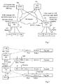
Fig. 1 . Thus, it is assumed that users of two different local networks A and B have agreed to set up a VPN tunnel between the networks to enable "safe" communication of data packets over apublic IP network 100, in this example the Internet, between devices in the opposite networks, e.g. due to the reasons presented above. - In
Fig. 1 , afirst gateway 102 and asecond gateway 104 are shown serving the first and second networks A and B, respectively, where a plurality of devices E1A, E2A, E3A... are present in the first network and plurality of devices E1B, E2B, E3B... are present in the second network. A private address space is used in each local network for internal communication, the address spaces potentially overlapping with each other since such address spaces are widely re-used in numerous local networks, generally. It is further assumed that eachgateway - Before establishing the VPN tunnel, each
gateway gateways PKI server 108. A first step 1:1 illustrates schematically the DNS registration and key establishment made by both gateways, as shown by the two-way arrows in the figure. This step can thus be executed according to regular procedures which are not necessary to describe here further to explain this example. - The following steps 1:2A and 1:2B illustrate that the VPN tunnel is established between the gateways, and also that each gateway defines an IP address space for devices in the opposite local network, which has been selected as to avoid overlap with the IP address space used internally for its own devices. Thus,
gateway 102 defines an IP address space for devices of network B in step 1:2A, whilegateway 104 defines an IP address space for devices of network A in step 1:2B. Establishing the VPN includes, among other things, storing in each gateway the above defined IP address space, or at least an identification thereof, as well as the name and associated public IP address of the opposite gateway, which are available and retrieved from theDDNS 106. - In this way, a gateway in a local network can establish multiple VPN tunnels with gateways of other local networks, and a translation table or the like can be created in the gateway, containing at least a tunnel identity and a non-overlapping IP address space used in the network for each opposite local network. None of these IP address spaces should thus not overlap with any other IP address space used in that network. Whenever an incoming data packet is received from a device in any of the opposite local networks, the incoming VPN tunnel is identified and a local IP address, taken from the IP address space associated with that tunnel in the table, is used in the receiving network for the device of the sending network, which will be described in more detail below.
- As mentioned above, the translation table may contain an identification of the defined IP address space associated with each tunnel identity. For example, if the IP address spaces include IPv4 (IP fourth version) based addresses, a unique number in a second or third octet of each IP address can be allocated to represent the corresponding opposite local network. That unique number may then be sufficient for identifying the network in the table. For example, if the address space of 10.0.0.0/24 is used for devices within the present network, the following exemplary IP address spaces may be defined for different opposite networks: 10.0.1.0/24, 10.0.2.0/24, 10.0.3.0/24..., using the third octet as a network identification.
- Thereby, the correct VPN tunnel can also be determined for an outgoing packet based on the unique number in the internal destination address of that packet, such that the packet can then be sent via the determined VPN tunnel. It is assumed that the sending device can obtain knowledge of the IP address space that was defined for devices in the opposite local network and that the destination address in the packet is the one assigned to the receiving device.
- Returning to
Fig. 1 , a data packet is sent from one device E1B in local network B, directed to another device E3A in local network A. The packet has an internal header with local destination and source IP addresses, and is firstly received at thegateway 104 in a following step 1:3. In the internal header, the destination and source IP addresses of E3A and E1B, respectively, are addresses used in the sending network B, but not in the receiving network A. Therefore, a translation of these addresses is necessary for obtaining unambiguous addressing in the receiving network A, which will be made by thegateway 102 of the receiving network A. This will thus ensure that the packet reaches the intended destination device. - Before sending out the packet,
gateway 104 identifies the VPN tunnel with network A based on the private destination IP address in the internal header from the second or third octet in the manner described above, and adds an external header with the public IP addresses ofgateways public IP network 100 togateway 102 of network A, in a next step 1:5. The public destination IP address in the external header can then be used for routing the packet towardsgateway 102 through thepublic IP network 100 in a conventional manner. - When receiving the data packet,
gateway 102 removes the external header, having fulfilled its purpose, while the sending network can be deduced from the VPN tunnel used for transmitting the packet. It should be remembered that the received packet contains private destination and source addresses which were valid in the sending network B, but not in the receivingnetwork A. Gateway 102 therefore changes the destination and source addresses in the internal header of the packet, in a further step 1:6, by translating them into addresses used in the receiving network A. - In more detail, the destination address is changed to a destination address used in network A for device E3A, and the source address is changed to an internal source address of the selected address space used in network A for device E1B, the latter address being taken from the internal IP address space previously defined in step 1:2A by
gateway 102 for devices in network B. The latter address has been assigned to device E1B, along with the address assignments of other devices, during establishment of the VPN tunnel and this information has been stored at eachgateway -
Fig. 2 illustrates an example of how the header of the data packet discussed above can be configured in more detail at different stages of the packet transmission described forFig. 1 . The left side ofFig. 2 thus depicts the sending device E1B, thegateways - In this example, network B uses the address space 10.0.0.0/24 for its own devices and the address space 10.0.1.0/24 has been defined for devices of the opposite network A. The third octet in these address spaces thus indicates the device's network, i.e. in network B "0" indicates network B and "1" indicates network A. On the opposite side, network A also uses the address space 10.0.0.0/24 for its own devices and the address space 10.0.1.0/24 has likewise been defined for devices of the opposite network B. Thus in network A "0" indicates network A and "1" indicates network B, contrary to the situation in network B.
- When the packet sent from device E1B is firstly received at
gateway 104 in accordance with step 1:3 above, it has an internal header valid in network B with a destination address 10.0.1.11 which is valid for device E3A, and a source address 10.0.0.4 which is valid for device E1B. In accordance with step 1:4 above,gateway 104 adds an external header with a public destination address IPA ofgateway 102 and a public source address IPB ofgateway 104.Gateway 104 then identifies the correct VPN tunnel from the network indication of "1" pointing to network A, and sends the packet via the tunnel togateway 102, in accordance with step 1:5 above. - Having received the packet,
gateway 102 then removes the external header and changes the internal header by translating the private destination address to 10.0.0.11 and the source address to 10.0.1.4, which are valid in network A for devices E1B and E3A, respectively. The packet with the modified internal header is then finally forwarded to device E3A, in accordance with step 1:7 above. Hence, even if overlapping address spaces are used in the networks A and B as described above, the destination and source addresses in the internal header will identify the respective devices properly and without risk for confusion in the receiving network A. - Moreover, device E3A can send a data packet as a reply to device E1B using the received source address as destination address and its own private address as source address, which are both valid in network A. In that case, the above procedure will be repeated in the reverse direction and the receiving
gateway 104 will thus change the internal header by translating the destination and source addresses back to the ones valid in network B, i.e. 10.0.0.4 (source) and 10.0.1.11 (destination). - A procedure for communicating data packets between a first communications device in a first local network and a second communications device in an opposite second local network, as executed by a gateway of the first local network, will now be described with reference to the flow chart in
Fig. 3 . It is assumed that the private IP addresses used in the first and second local networks for their own respective devices are potentially overlapping with each other, e.g. by belonging to an address space that is typically re-used in plural local networks. - In a
first step 300, a VPN tunnel is established with a gateway in the opposite second local network which includes, among other things, storing a name and associated public IP address of the opposite gateway, which is available and can be retrieved from a DDNS. In anext step 302, a private IP address space is defined for the second network which has been selected as to be non-overlapping with the private IP address space used in the first network for its own devices. It is further assumed that the opposite second gateway likewise defines a non-overlapping private IP address space for the first network as well.Steps - At some point later in a
further step 304, an incoming data packet is received via the VPN tunnel, which packet has been sent from the second device and having an internal header with destination and source addresses used in the second network for the first and second devices, respectively. The first gateway then changes the destination and source addresses in the internal header, in anext step 306, to destination and source addresses used in first network for the first and second devices, respectively. In a last shownstep 308, the packet is forwarded with the modified internal header to the first device. The first device is then able to respond by sending a data packet to the second device using the received source address as destination address which will be translated once again by the receiving first gateway, in the manner described above. - An arrangement in a
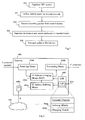
first gateway 400 will now be described in more detail with reference to the block diagram inFig. 4 . It is assumed that thegateway 400 is serving a first local network, and is capable of communicating data packets between a first communications device in the first local network and a second communications device in a second local network served by a second gateway. It is also assumed that a VPN tunnel has been established between the first gateway and the second gateway, a public IP address has been assigned to each gateway, and that potentially overlapping private IP addresses are used for devices in each local network. - The
gateway 400 comprises IPaddress defining means 400a adapted to define a selected internal IP address space to be used in the first local network for devices in the second local network. The selected IP address space is separate from, i.e. non-overlapped with, an internal IP address space used in the first local network for devices in the first local network. - The
gateway 400 further comprises receiving means 400b adapted to receive an incoming data packet P from the second device. The incoming packet P has external and internal IP headers, the latter including an internal destination address used in the second local network for the first device and an internal source address used in the second local network for the second device. - The
gateway 400 also comprises IPaddress changing means 400c adapted to change the internal destination address to an internal destination address used in the first local network for the first device, and to change the internal source address to an internal source address of the selected address space used in the first local network for the second device and being within the selected internal IP address space. The IPaddress changing means 400c is also adapted to remove the external IP header from the received packet. - The
gateway 400 also comprises forwarding means 400d adapted to forward the incoming packet P' to the second device with a modified internal IP header including the changed internal destination and source addresses. Thereby, the addresses in the packet header are separate from and cannot be confused with any addresses of other devices valid in the second local network. - So far, it has been described basically what is made at the receiving side of a data packet transmission, e.g. procedures and functions in the
gateway 102 at network A inFig. 1 and by means of the flow chart inFig. 3 . It will now also be described with reference to the flow chart inFig. 5 what is performed by the gateway at the sending side of the data packet transmission, e.g., procedures and functions in thegateway 104 at network B inFig. 1 . Using the same situation as forFig. 3 , the following further procedure may be executed by the first gateway when receiving an outgoing data packet from the first device directed to the second device in the opposite second network. - A
first step 500 thus illustrates that an outgoing data packet coming from the first device, is received. The outgoing packet has an internal IP header including an internal destination address used in the first local network for the second device and an internal source address used in the first local network for the first device. In afurther step 502, the correct VPN tunnel is determined for the outgoing packet based on the internal destination address. For example, if the IP address spaces used include IPv4-based addresses, a unique number in a second or third octet of each IP address can be allocated to represent the corresponding opposite local network, and the correct VPN tunnel is then determined from that number. - In a
next step 504, the packet is encapsulated with an external IP header including the public IP addresses of the first and second gateways as external destination and source addresses, respectively, allowing for routing over the public IP network. In alast step 506, the outgoing packet is sent to the second gateway over the public IP network via the determined VPN tunnel. - It is possible to establish VPN tunnels between the first local network and a plurality of opposite local networks. In that case, a selected internal IP address space is defined for each opposite network to be used in the first local network for devices in each respective opposite network. Each selected IP address space should then be separate from, i.e. non-overlapped with, any other address space used in the first local network.
- A unique number in a second or third octet of each IP address can further be allocated to represent each corresponding opposite local network. In that case, a correct VPN tunnel can be determined for each outgoing packet based on that unique number in an internal destination address in the outgoing packet, and the packet will then be sent via the determined VPN tunnel. Further, establishing the VPN tunnels includes adding in the gateway of each local network a DNS-registered name and corresponding public PKI key of each opposite gateway.
- According to further possible embodiments illustrated in
Fig. 4 , atrust list 400e with trusted parties can be created for the first local network in thefirst gateway 400. When a request or the like is received for establishing VPN tunnel with a gateway of acandidate network 402, the VPN tunnel can be admitted for establishment if the candidate local network is associated with a first party present in thetrust list 400e. Furthermore, thegateway 400 may be configured such that the VPN tunnel can also be admitted for establishment if the candidatelocal network 402 is indirectly associated with the first party in the trust list by being associated with a second party present in a trust list of the first party. Thegateway 400 may be further configured such that the VPN tunnel can be admitted for establishment depending on a predetermined number of trust levels approved for the first local network. - As mentioned above, the candidate
local network 402 may be evaluated for establishment of a VPN tunnel, based on thetrust list 400e, in response to a VPN tunnel request R from the candidate local network. Thegateway 400 may be further configured such that an established VPN tunnel between two local networks is terminated automatically if a trust list associated with either network is modified to disqualify the VPN tunnel. - An exemplary procedure for using a trust list in the above manner at a first gateway for VPN tunnel requests, will now be briefly described with reference to the flow chart in
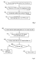
Fig. 6 . Firstly, a trust list with trusted parties is created for the first local network, as schematically illustrated by afirst step 600. When a request for establishing VPN tunnel with gateway in candidate network is received at some point according to anext step 602, the candidate network is evaluated based on the created trust list in a followingstep 604. - It is then determined if the requested VPN tunnel can be admitted in a
step 606, which can be deduced from the trust list as described above, e.g. considering multiple levels of trust lists of already trusted parties. If so, the VPN tunnel is established, as shown by afinal step 608, and data packets can be communicated according to the above description. If the trust list does not allow for the VPN tunnel, the request is rejected or simply ignored, in astep 610. - As further illustrated in
Fig. 4 , the functional units in thegateway 400 described above can be implemented as program modules of acomputer program 404 comprising code means which when run on thefirst gateway 400 causes the first gateway to perform the above-described functions and steps of the first gateway. In this embodiment, thecomputer program 404 is carried by acomputer program product 406 comprising a computer readable medium on which the computer program is stored. - The program modules of the
computer program 404 include at least an addressspace defining module 404a and anaddress changing module 404b. The addressspace defining module 404a is capable of defining a selected internal IP address space to be used in the first local network for devices in the second local network, the selected IP address space being separate from, i.e. non-overlapped with, an internal IP address space used in the first local network for devices in the first local network. - The
address changing module 404b is capable of, when receiving from the second device via the VPN tunnel an incoming packet having an internal IP header including an internal destination address used in the second local network for the first device and an internal source address used in the second local network for the second device, changing the internal destination address to an internal destination address used in the first local network for the first device, and changing the internal source address to an internal source address of the selected address space used in the first local network for the second device and being within the selected internal IP address space. The incoming packet can then be forwarded to the first device with a modified internal IP header including the changed internal destination and source addresses. - The code means of the
computer program 404 andcomputer program product 406 may also cause the first gateway to perform the following functions. - When the incoming packet has an external IP header including the public IP addresses of the first and second gateways as external destination and source addresses, respectively, the code means may cause the first gateway to remove the external IP header from the incoming packet.
- When an outgoing data packet is received from the first device, the outgoing packet having an internal IP header including an internal destination address used in the first local network for the second device and an internal source address used in the first local network for the first device, the code means may also cause the first gateway to:
- encapsulate the packet with an external IP header including the public IP addresses of the gateways as external destination and source addresses, respectively, and
- determine the correct VPN tunnel for the outgoing packet based on the internal destination address,
- The code means may also cause the first gateway to establish VPN tunnels between the first local network and a plurality of opposite local networks, and to define a selected internal IP address space for each opposite network to be used in the first local network for devices in each respective opposite network, each selected IP address space being separate from, i.e. non-overlapped with, any other address space used in the first local network.
- The selected IP address spaces may include IPv4-based addresses, and a unique number in a second or third octet of each IP address may then be allocated to represent the corresponding opposite local network. In that case, the code means may also cause the first gateway to determine a VPN tunnel for each outgoing packet based on the unique number in an internal destination address in the outgoing packet, wherein the packet is then sent via the determined VPN tunnel.
- The code means may also cause the first gateway to establish the VPN tunnels by adding a DNS-registered name and corresponding public PKI key of each opposite gateway. The public PKI key and a corresponding private PKI key may have been generated for each gateway and the public PKI keys are stored in a PKI server accessible for the gateways.
- When a trust list with trusted parties has been created for the first local network, the code means may cause the first gateway to admit a VPN tunnel for establishment between the first local network and a candidate local network if the candidate local network is associated with a first party present in the trust list.
- The code means may also cause the first gateway to admit the VPN tunnel for establishment if the candidate local network is indirectly associated with the first party in the trust list by being associated with a second party present in a trust list of the first party.
- The code means may also cause the first gateway to admit the VPN tunnel for establishment depending on a predetermined number of trust levels approved for the first local network.
- The code means may also cause the first gateway to evaluate the candidate local network for establishment of VPN tunnel in response to a VPN tunnel request from the candidate local network.
- The code means may also cause the first gateway to terminate an established VPN tunnel between two local networks automatically if a trust list associated with either network is modified to disqualify the VPN tunnel.
- It should be noted that
Fig. 4 merely illustrates various exemplary functional units and program modules in thegateway 400 in a logical sense, while the skilled person is free to implement the described functions in practice using any suitable software and hardware means. Thus, the invention is generally not limited to the shown structure of thegateway 400. For example, the computer program product may be a flash memory, ROM (Read-Only Memory) or an EEPROM (Electrically Erasable Programmable ROM), and the computer program modules described above could in alternative embodiments be distributed on different computer program products in the form of memories within thegateway 400. - While the invention has been described with reference to specific exemplary embodiments, the description is generally only intended to illustrate the inventive concept and should not be taken as limiting the scope of the invention. The invention is defined by the appended claims.
Claims (20)
- A method of communicating data packets between a first communications device (E3A) in a first local network and a second communications device (E1B) in a second local network, wherein potentially overlapping private IP addresses are used for devices in the first and second local networks, comprising the steps of:- establishing a VPN, Virtual Private Network, tunnel between a first gateway (A) serving the first local network and a second gateway (B) serving the second local network, wherein a public IP address has been assigned to each gateway,- defining, in the first gateway, a selected internal IP address space to be used in the first local network for devices in the second local network, the selected IP address space being separate from, i.e. non-overlapped with, an internal IP address space used in the first local network for devices in the first local network,- receiving, in the first gateway, an incoming data packet from the second device (E1B) via said VPN tunnel, the incoming packet having an internal IP header including an internal destination address used in the second local network for the first device and an internal source address used in the second local network for the second device,- changing, in the first gateway (A), said internal destination address to an internal destination address used in the first local network for the first device,- changing, in the first gateway (A), said internal source address to an internal source address of the selected address space used in the first local network for the second device and being within said selected internal IP address space, and- forwarding the incoming packet to the first device (E3A) with a modified internal IP header including the changed internal destination and source addresses, characterized in that the method further comprises:- creating a trust list with trusted parties for the first local network, and- admitting a VPN tunnel for establishment between the first local network and a candidate local network if the candidate local network is associated with a first party present in said trust list.
- A method according to claim 1, the incoming packet further having an external IP header including the public IP addresses of said first and second gateways as external destination and source addresses, respectively, wherein the external IP header is removed from the incoming packet by the first gateway.
- A method according to claim 1 or 2, comprising the following further steps:- receiving, in the first gateway, an outgoing data packet from the first device, the outgoing packet having an internal IP header including an internal destination address used in the first local network for the second device and an internal source address used in the first local network for the first device,- encapsulating the packet with an external IP header including the public IP addresses of said gateways as external destination and source addresses, respectively,- determining the correct VPN tunnel for the outgoing packet based on said internal destination address, and- sending the outgoing packet to the second gateway via the VPN tunnel.
- A method according to any of claims 1-3, wherein VPN tunnels are established between the first local network and a plurality of opposite local networks, and a selected internal IP address space is defined for each opposite network to be used in the first local network for devices in each respective opposite network, each selected IP address space being separate from, i.e. non-overlapped with, any other address space used in the first local network.
- A method according to claim 1-4, wherein the VPN tunnel is admitted for establishment if the candidate local network is indirectly associated with said first party in the trust list by being associated with a second party present in a trust list of the first party.
- A method according to claim 5, wherein the candidate local network is evaluated for establishment of VPN tunnel in response to a VPN tunnel request from the candidate local network.
- A method according to any of claims 5 or 6, wherein an established VPN tunnel between two local networks is terminated automatically if a trust list associated with either network is modified to disqualify the VPN tunnel.
- An arrangement in a first gateway (A) serving a first local network, capable of communicating data packets between a first communications device (E1A) in the first local network and a second communications device (E3B) in a second local network served by a second gateway (B), the first gateway being adapted to establish a VPN tunnel between the first gateway and the second gateway wherein a public IP address has been assigned to each gateway, and potentially overlapping private IP addresses are used for devices in each local network, comprising:- IP address defining means (400a) adapted to define a selected internal IP address space to be used in the first local network for devices in the second local network, the selected IP address space being separate from, i.e. non-overlapped with, an internal IP address space used in the first local network for devices in the first local network,- receiving means (400b) adapted to receive an incoming data packet from the second device via said VPN tunnel, the incoming packet having an internal IP header including an internal destination address used in the second local network for the first device and an internal source address used in the second local network for the second device,- IP address changing means (400c) adapted to change said internal destination address to an internal destination address used in the first local network for the first device, and to change said internal source address to an internal source address of the selected address space used in the first local network for the second device and being within said selected internal IP address space, and- forwarding means (400d) adapted to forward the incoming packet to the second device with a modified internal IP header including the changed internal destination and source addresses,wherein the arrangement is characterized by being further adapted to create a trust list with trusted parties for the first local network, and to admit a VPN tunnel for establishment between the first local network and a candidate local network if the candidate local network is associated with a first party present in said trust list.
- An arrangement according to claim 8, the incoming packet further having an external IP header including the public IP addresses of said first and second gateways as external destination and source addresses, respectively, wherein the IP address changing means is further adapted to remove the external IP header from the incoming packet by the first gateway.
- An arrangement according to claim 8 or 9, further adapted to:- receive an outgoing data packet from the first device, the outgoing packet having an internal IP header including an internal destination address used in the first local network for the second device and an internal source address used in the first local network for the first device,- encapsulate the packet with an external IP header including the public IP addresses of said gateways as external destination and source addresses, respectively,- determine the correct VPN tunnel for the outgoing packet based on said internal destination address, and- send the outgoing packet to the second gateway via the VPN tunnel.
- An arrangement according to any of claims 8-10, wherein VPN tunnels are established between the first local network and a plurality of opposite local networks, and a selected internal IP address space is defined for each opposite network to be used in the first local network for devices in each respective opposite network, each selected IP address space being separate from, i.e. non-overlapped with, any other address space used in the first local network.
- An arrangement according to claim 11, wherein the selected IP address spaces include IPv4-based addresses, and a unique number in a second or third octet of each IP address is allocated to represent the corresponding opposite local network.
- An arrangement according to claim 12, further adapted to determine a VPN tunnel for each outgoing packet based on said unique number in an internal destination address in the outgoing packet, and then send the packet via the determined VPN tunnel.
- An arrangement according to claim 13, wherein establishing the VPN tunnels includes adding in the gateway of each local network a DNS-registered name and corresponding public PKI key of each opposite gateway.
- An arrangement according to claim 14, wherein said public PKI key and a corresponding private PKI key have been generated for each gateway and the public PKI keys are stored in a PKI server accessible for the gateways.
- An arrangement according to claim 8, further adapted to admit the VPN tunnel for establishment if the candidate local network is indirectly associated with said first party in the trust list by being associated with a second party present in a trust list of the first party.
- An arrangement according to claim 16, further adapted to admit the VPN tunnel for establishment depending on a predetermined number of trust levels approved for the first local network.
- An arrangement according to claim 16 or 17, further adapted to evaluate the candidate local network for establishment of VPN tunnel in response to a VPN tunnel request from the candidate local network.
- An arrangement according to any of claims 16-18, further adapted to terminate an established VPN tunnel between two local networks automatically if a trust list associated with either network is modified to disqualify the VPN tunnel.
- A computer program product (400e) configured for a first gateway (A) that serves a first local network and is capable of communicating data packets between a first communications device (E1A) in the first local network and a second communications device (E3B) in a second local network served by a second gateway (B), wherein a VPN tunnel is established between the first gateway (A) and the second gateway (B), a public IP address has been assigned to each gateway, and potentially overlapping private IP addresses are used for devices in each local network, wherein the computer program comprises code means which when run on the first gateway causes the first gateway to:- define a selected internal IP address space to be used in the first local network for devices in the second local network, the selected IP address space being separate from, i.e. non-overlapped with, an internal IP address space used in the first local network for devices in the first local network, and
when receiving from the second device (E1B) via said VPN tunnel an incoming packet having an internal IP header including an internal destination address used in the second local network for the first device and an internal source address used in the second local network for the second device,- change said internal destination address to an internal destination address used in the first local network for the first device,- change said internal source address to an internal source address of the selected address space used in the first local network for the second device and being within said selected internal IP address space,wherein the computer program is characterized by further causing the first gateway to:
before the incoming packet is forwarded to the first device (E3A) with a modified internal IP header including the changed internal destination and source addresses,- create a trust list with trusted parties for the first local network, and- admit a VPN tunnel for establishment between the first local network and a candidate local network if the candidate local network is associated with a first party present in said trust list.
Applications Claiming Priority (2)
| Application Number | Priority Date | Filing Date | Title |
|---|---|---|---|
| US3819208P | 2008-03-20 | 2008-03-20 | |
| PCT/SE2009/050292 WO2009116945A1 (en) | 2008-03-20 | 2009-03-20 | Method and apparatus for communication of data packets between local networks |
Publications (3)
| Publication Number | Publication Date |
|---|---|
| EP2253123A1 EP2253123A1 (en) | 2010-11-24 |
| EP2253123A4 EP2253123A4 (en) | 2011-06-15 |
| EP2253123B1 true EP2253123B1 (en) | 2013-08-07 |
Family
ID=41091161
Family Applications (2)
| Application Number | Title | Priority Date | Filing Date |
|---|---|---|---|
| EP20090721670 Active EP2253123B1 (en) | 2008-03-20 | 2009-03-20 | Method and apparatus for communication of data packets between local networks |
| EP09721812.7A Not-in-force EP2253124B1 (en) | 2008-03-20 | 2009-03-20 | Method and apparatus for communication of data packets between local networks |
Family Applications After (1)
| Application Number | Title | Priority Date | Filing Date |
|---|---|---|---|
| EP09721812.7A Not-in-force EP2253124B1 (en) | 2008-03-20 | 2009-03-20 | Method and apparatus for communication of data packets between local networks |
Country Status (6)
| Country | Link |
|---|---|
| US (2) | US8559448B2 (en) |
| EP (2) | EP2253123B1 (en) |
| JP (2) | JP5335886B2 (en) |
| ES (1) | ES2429121T3 (en) |
| IL (2) | IL207903A (en) |
| WO (2) | WO2009116948A1 (en) |
Families Citing this family (105)
| Publication number | Priority date | Publication date | Assignee | Title |
|---|---|---|---|---|
| US8160255B2 (en) * | 2006-04-24 | 2012-04-17 | Cisco Technology, Inc. | System and method for encrypted group network communication with point-to-point privacy |
| US8625610B2 (en) * | 2007-10-12 | 2014-01-07 | Cisco Technology, Inc. | System and method for improving spoke to spoke communication in a computer network |
| CA2703204C (en) * | 2007-10-24 | 2014-08-19 | Jonathan Peter Deutsch | Various methods and apparatuses for a central management station for automatic distribution of configuration information to remote devices |
| US8346961B2 (en) | 2007-12-12 | 2013-01-01 | Cisco Technology, Inc. | System and method for using routing protocol extensions for improving spoke to spoke communication in a computer network |
| US8837491B2 (en) | 2008-05-27 | 2014-09-16 | Glue Networks | Regional virtual VPN |
| KR20100040658A (en) * | 2008-10-10 | 2010-04-20 | 삼성전자주식회사 | Method and apparatus for preventing ip address conflict in remote access service of upnp network |
| US9319300B2 (en) * | 2008-12-09 | 2016-04-19 | Glue Networks, Inc. | Systems and methods for determining endpoint configurations for endpoints of a virtual private network (VPN) and deploying the configurations to the endpoints |
| US8726007B2 (en) * | 2009-03-31 | 2014-05-13 | Novell, Inc. | Techniques for packet processing with removal of IP layer routing dependencies |
| WO2010138036A1 (en) * | 2009-05-29 | 2010-12-02 | Telefonaktiebolaget L M Ericsson (Publ) | Content sharing system performance improvement |
| US8687631B2 (en) | 2009-10-16 | 2014-04-01 | Cisco Technology, Inc. | System and method for providing a translation mechanism in a network environment |
| EP2494750A1 (en) * | 2009-10-29 | 2012-09-05 | Sierra Wireless, Inc. | Routing device and method of configuration for network name resolution of same |
| JP5357707B2 (en) * | 2009-11-11 | 2013-12-04 | 株式会社日立製作所 | Gateway device and port number assigning method |
| JP5260487B2 (en) * | 2009-12-28 | 2013-08-14 | 日本電信電話株式会社 | Address determination device, address determination method, and address determination program |
| JP5569697B2 (en) * | 2011-03-09 | 2014-08-13 | 村田機械株式会社 | Relay server and relay communication system |
| JP5452527B2 (en) * | 2011-03-11 | 2014-03-26 | エヌ・ティ・ティ・コムウェア株式会社 | Address management device, address management method, and address management program |
| JP5552460B2 (en) * | 2011-04-13 | 2014-07-16 | 日本電信電話株式会社 | Inter-base connection system, inter-base connection method, address conversion information generation apparatus, address conversion information generation method, and program |
| CN102333022B (en) * | 2011-05-31 | 2014-01-15 | 广东省电力调度中心 | Method for interacting cross-safety protection region information in power communication network and protection system |
| CN107342991B (en) * | 2011-07-08 | 2021-12-24 | 威尔耐特斯公司 | Dynamic VPN address allocation |
| WO2013080475A1 (en) * | 2011-11-30 | 2013-06-06 | 村田機械株式会社 | Relay server device and relay communication system |
| US10044582B2 (en) * | 2012-01-28 | 2018-08-07 | A10 Networks, Inc. | Generating secure name records |
| US8954964B2 (en) * | 2012-02-27 | 2015-02-10 | Ca, Inc. | System and method for isolated virtual image and appliance communication within a cloud environment |
| US8930493B2 (en) | 2012-03-20 | 2015-01-06 | International Business Machines Corporation | Inter-domain replication of service information |
| CN104901943A (en) * | 2012-03-31 | 2015-09-09 | 北京奇虎科技有限公司 | Method and system for accessing website |
| TWI482469B (en) * | 2012-05-23 | 2015-04-21 | Gemtek Technology Co Ltd | Routing device |
| US9407548B2 (en) | 2013-01-02 | 2016-08-02 | Acceleration Systems, LLC | ReNAT systems and methods |
| KR102103704B1 (en) * | 2013-01-02 | 2020-04-24 | 스카이캐스터, 엘엘씨 | Systems and Methods for Providing a ReNAT Communications Environment |
| US9760528B1 (en) | 2013-03-14 | 2017-09-12 | Glue Networks, Inc. | Methods and systems for creating a network |
| US9722918B2 (en) | 2013-03-15 | 2017-08-01 | A10 Networks, Inc. | System and method for customizing the identification of application or content type |
| US9928082B1 (en) | 2013-03-19 | 2018-03-27 | Gluware, Inc. | Methods and systems for remote device configuration |
| EP2981030B1 (en) * | 2013-03-26 | 2019-07-31 | KDDI Corporation | Transfer device |
| EP3021555B1 (en) | 2013-07-12 | 2018-09-12 | Huawei Technologies Co., Ltd. | Message processing method and device |
| US9887960B2 (en) | 2013-08-14 | 2018-02-06 | Nicira, Inc. | Providing services for logical networks |
| US9952885B2 (en) | 2013-08-14 | 2018-04-24 | Nicira, Inc. | Generation of configuration files for a DHCP module executing within a virtualized container |
| US9503371B2 (en) | 2013-09-04 | 2016-11-22 | Nicira, Inc. | High availability L3 gateways for logical networks |
| US9577845B2 (en) | 2013-09-04 | 2017-02-21 | Nicira, Inc. | Multiple active L3 gateways for logical networks |
| TW201529224A (en) * | 2013-10-04 | 2015-08-01 | Fujimi Inc | Polishing apparatus and polishing method |
| US10063458B2 (en) | 2013-10-13 | 2018-08-28 | Nicira, Inc. | Asymmetric connection with external networks |
| JP6894060B2 (en) * | 2014-02-06 | 2021-06-23 | イー^ナット テクノロジーズ リミティド ライアビリティ カンパニー | Systems and methods that provide a composite secure link architecture |
| EP3103221B1 (en) * | 2014-02-06 | 2020-07-01 | Skycasters, LLC | Systems and methods for providing a multiple secure link architecture |
| US9590901B2 (en) | 2014-03-14 | 2017-03-07 | Nicira, Inc. | Route advertisement by managed gateways |
| US9225597B2 (en) | 2014-03-14 | 2015-12-29 | Nicira, Inc. | Managed gateways peering with external router to attract ingress packets |
| US9419855B2 (en) | 2014-03-14 | 2016-08-16 | Nicira, Inc. | Static routes for logical routers |
| US9647883B2 (en) | 2014-03-21 | 2017-05-09 | Nicria, Inc. | Multiple levels of logical routers |
| US9338091B2 (en) | 2014-03-27 | 2016-05-10 | Nicira, Inc. | Procedures for efficient cloud service access in a system with multiple tenant logical networks |
| US9794186B2 (en) | 2014-03-27 | 2017-10-17 | Nicira, Inc. | Distributed network address translation for efficient cloud service access |
| US9825854B2 (en) * | 2014-03-27 | 2017-11-21 | Nicira, Inc. | Host architecture for efficient cloud service access |
| WO2015147943A1 (en) * | 2014-03-27 | 2015-10-01 | Nicira, Inc. | Distributed network address translation for cloud service access |
| US9906422B2 (en) | 2014-05-16 | 2018-02-27 | A10 Networks, Inc. | Distributed system to determine a server's health |
| US9876714B2 (en) | 2014-11-14 | 2018-01-23 | Nicira, Inc. | Stateful services on stateless clustered edge |
| US10044617B2 (en) | 2014-11-14 | 2018-08-07 | Nicira, Inc. | Stateful services on stateless clustered edge |
| US11533255B2 (en) | 2014-11-14 | 2022-12-20 | Nicira, Inc. | Stateful services on stateless clustered edge |
| US9866473B2 (en) | 2014-11-14 | 2018-01-09 | Nicira, Inc. | Stateful services on stateless clustered edge |
| US10129180B2 (en) | 2015-01-30 | 2018-11-13 | Nicira, Inc. | Transit logical switch within logical router |
| US9785412B1 (en) | 2015-02-27 | 2017-10-10 | Glue Networks, Inc. | Methods and systems for object-oriented modeling of networks |
| US10038628B2 (en) | 2015-04-04 | 2018-07-31 | Nicira, Inc. | Route server mode for dynamic routing between logical and physical networks |
| US11212877B2 (en) * | 2015-07-06 | 2021-12-28 | Icom Incorporated | Relaying device, method of relaying communication packet and voice communication system |
| US10230629B2 (en) | 2015-08-11 | 2019-03-12 | Nicira, Inc. | Static route configuration for logical router |
| US10075363B2 (en) | 2015-08-31 | 2018-09-11 | Nicira, Inc. | Authorization for advertised routes among logical routers |
| US9787581B2 (en) | 2015-09-21 | 2017-10-10 | A10 Networks, Inc. | Secure data flow open information analytics |
| US10095535B2 (en) | 2015-10-31 | 2018-10-09 | Nicira, Inc. | Static route types for logical routers |
| CN105681486B (en) * | 2016-01-15 | 2018-11-23 | 华洋通信科技股份有限公司 | A kind of across broadcast domain data communications method of XinIP |
| EP3223494A1 (en) * | 2016-03-21 | 2017-09-27 | Thomson Licensing | Method and apparatus for interconnection between networks |
| US10333849B2 (en) | 2016-04-28 | 2019-06-25 | Nicira, Inc. | Automatic configuration of logical routers on edge nodes |
| US10841273B2 (en) | 2016-04-29 | 2020-11-17 | Nicira, Inc. | Implementing logical DHCP servers in logical networks |
| US10484515B2 (en) | 2016-04-29 | 2019-11-19 | Nicira, Inc. | Implementing logical metadata proxy servers in logical networks |
| US10091161B2 (en) | 2016-04-30 | 2018-10-02 | Nicira, Inc. | Assignment of router ID for logical routers |
| US10153973B2 (en) | 2016-06-29 | 2018-12-11 | Nicira, Inc. | Installation of routing tables for logical router in route server mode |
| US10560320B2 (en) | 2016-06-29 | 2020-02-11 | Nicira, Inc. | Ranking of gateways in cluster |
| US10812348B2 (en) | 2016-07-15 | 2020-10-20 | A10 Networks, Inc. | Automatic capture of network data for a detected anomaly |
| US10341118B2 (en) | 2016-08-01 | 2019-07-02 | A10 Networks, Inc. | SSL gateway with integrated hardware security module |
| US10454758B2 (en) | 2016-08-31 | 2019-10-22 | Nicira, Inc. | Edge node cluster network redundancy and fast convergence using an underlay anycast VTEP IP |
| US10341236B2 (en) | 2016-09-30 | 2019-07-02 | Nicira, Inc. | Anycast edge service gateways |
| US10382562B2 (en) | 2016-11-04 | 2019-08-13 | A10 Networks, Inc. | Verification of server certificates using hash codes |
| US10250475B2 (en) | 2016-12-08 | 2019-04-02 | A10 Networks, Inc. | Measurement of application response delay time |
| US10237123B2 (en) | 2016-12-21 | 2019-03-19 | Nicira, Inc. | Dynamic recovery from a split-brain failure in edge nodes |
| US10742746B2 (en) | 2016-12-21 | 2020-08-11 | Nicira, Inc. | Bypassing a load balancer in a return path of network traffic |
| US10212071B2 (en) | 2016-12-21 | 2019-02-19 | Nicira, Inc. | Bypassing a load balancer in a return path of network traffic |
| US10616045B2 (en) | 2016-12-22 | 2020-04-07 | Nicira, Inc. | Migration of centralized routing components of logical router |
| US10397270B2 (en) | 2017-01-04 | 2019-08-27 | A10 Networks, Inc. | Dynamic session rate limiter |
| US10187377B2 (en) | 2017-02-08 | 2019-01-22 | A10 Networks, Inc. | Caching network generated security certificates |
| US10425330B2 (en) * | 2017-04-24 | 2019-09-24 | International Business Machines Corporation | Routing packets in multiple destination networks with overlapping address spaces |
| US10637800B2 (en) | 2017-06-30 | 2020-04-28 | Nicira, Inc | Replacement of logical network addresses with physical network addresses |
| US10681000B2 (en) | 2017-06-30 | 2020-06-09 | Nicira, Inc. | Assignment of unique physical network addresses for logical network addresses |
| US11296984B2 (en) | 2017-07-31 | 2022-04-05 | Nicira, Inc. | Use of hypervisor for active-active stateful network service cluster |
| US10951584B2 (en) | 2017-07-31 | 2021-03-16 | Nicira, Inc. | Methods for active-active stateful network service cluster |
| US11570092B2 (en) | 2017-07-31 | 2023-01-31 | Nicira, Inc. | Methods for active-active stateful network service cluster |
| US10104039B1 (en) * | 2017-09-28 | 2018-10-16 | Cloudflare, Inc. | Establishing and using a tunnel from an origin server in a distributed edge compute and routing service |
| US20190104105A1 (en) * | 2017-10-04 | 2019-04-04 | Harris Solutions NY, Inc. | Systems and methods for creating a virtual layer 2 network through tethering |
| CN109962989B (en) * | 2017-12-25 | 2022-03-01 | 中国电信股份有限公司 | Method, device and system for traversing network address gateway |
| US11153122B2 (en) | 2018-02-19 | 2021-10-19 | Nicira, Inc. | Providing stateful services deployed in redundant gateways connected to asymmetric network |
| US10708125B1 (en) * | 2018-09-05 | 2020-07-07 | Amazon Technologies, Inc. | Gateway configuration using a network manager |
| US10931560B2 (en) | 2018-11-23 | 2021-02-23 | Vmware, Inc. | Using route type to determine routing protocol behavior |
| US10797998B2 (en) | 2018-12-05 | 2020-10-06 | Vmware, Inc. | Route server for distributed routers using hierarchical routing protocol |
| US10938788B2 (en) | 2018-12-12 | 2021-03-02 | Vmware, Inc. | Static routes for policy-based VPN |
| CN111698338B (en) * | 2019-03-15 | 2021-10-01 | 华为技术有限公司 | Data transmission method and computer system |
| US11095480B2 (en) | 2019-08-30 | 2021-08-17 | Vmware, Inc. | Traffic optimization using distributed edge services |
| US11606294B2 (en) | 2020-07-16 | 2023-03-14 | Vmware, Inc. | Host computer configured to facilitate distributed SNAT service |
| US11616755B2 (en) | 2020-07-16 | 2023-03-28 | Vmware, Inc. | Facilitating distributed SNAT service |
| US11611613B2 (en) | 2020-07-24 | 2023-03-21 | Vmware, Inc. | Policy-based forwarding to a load balancer of a load balancing cluster |
| US11902050B2 (en) | 2020-07-28 | 2024-02-13 | VMware LLC | Method for providing distributed gateway service at host computer |
| US11451413B2 (en) | 2020-07-28 | 2022-09-20 | Vmware, Inc. | Method for advertising availability of distributed gateway service and machines at host computer |
| US11870751B2 (en) | 2021-10-11 | 2024-01-09 | Cisco Technology, Inc. | Smart service discovery to interconnect clusters having overlapping IP address space |
| US11799761B2 (en) | 2022-01-07 | 2023-10-24 | Vmware, Inc. | Scaling edge services with minimal disruption |
| US11962564B2 (en) | 2022-02-15 | 2024-04-16 | VMware LLC | Anycast address for network address translation at edge |
| US12081430B2 (en) * | 2022-07-08 | 2024-09-03 | Cisco Technology, Inc. | Marking spoke links for network segregation and service chaining in hub and spoke overlay networks |
Family Cites Families (14)
| Publication number | Priority date | Publication date | Assignee | Title |
|---|---|---|---|---|
| US6888837B1 (en) * | 1999-03-23 | 2005-05-03 | Nortel Networks Limited | Network address translation in a network having multiple overlapping address domains |
| US6493765B1 (en) | 1999-03-23 | 2002-12-10 | Nortel Networks Limited | Domain name resolution in a network having multiple overlapping address domains |
| US7099319B2 (en) * | 2002-01-23 | 2006-08-29 | International Business Machines Corporation | Virtual private network and tunnel gateway with multiple overlapping, remote subnets |
| US7395354B2 (en) | 2002-02-21 | 2008-07-01 | Corente, Inc. | Methods and systems for resolving addressing conflicts based on tunnel information |
| US8533282B2 (en) * | 2002-02-25 | 2013-09-10 | Broadcom Corporation | System, method and computer program product for selectively caching domain name system information on a network gateway |
| KR100485801B1 (en) * | 2002-03-07 | 2005-04-28 | 삼성전자주식회사 | Network connecting apparatus and method for offering direct connection between network devices existing different private networks |
| US7333510B1 (en) * | 2002-07-12 | 2008-02-19 | Cisco Technology, Inc. | Method and apparatus for providing IPv6 networks to communicate with overlapping IPv4 networks using NAT-PT |
| US20040148439A1 (en) * | 2003-01-14 | 2004-07-29 | Motorola, Inc. | Apparatus and method for peer to peer network connectivty |
| CN1301611C (en) * | 2003-01-21 | 2007-02-21 | 三星电子株式会社 | Gateway for supporting communications between network devices of different private networks |
| US20050076142A1 (en) | 2003-09-19 | 2005-04-07 | Chin Kwan Wu | Automatic sub domain delegation of private name spaces for home-to-home virtual private networks |
| US20050257039A1 (en) * | 2004-05-13 | 2005-11-17 | Netgear, Inc. | Virtual private network configuration system and method |
| JP4327142B2 (en) * | 2005-09-29 | 2009-09-09 | パナソニック株式会社 | Information processing system, tunnel communication device, tunnel communication method, proxy response device, and proxy response method |
| JP5132059B2 (en) * | 2006-01-30 | 2013-01-30 | 富士通株式会社 | Packet relay method and packet relay system |
| US7609701B2 (en) * | 2006-02-22 | 2009-10-27 | Zheng Yang | Communication using private IP addresses of local networks |
-
2009
- 2009-03-20 JP JP2011500742A patent/JP5335886B2/en not_active Expired - Fee Related
- 2009-03-20 JP JP2011500741A patent/JP2011515944A/en active Pending
- 2009-03-20 EP EP20090721670 patent/EP2253123B1/en active Active
- 2009-03-20 US US12/922,946 patent/US8559448B2/en not_active Expired - Fee Related
- 2009-03-20 EP EP09721812.7A patent/EP2253124B1/en not_active Not-in-force
- 2009-03-20 US US12/922,974 patent/US8295285B2/en active Active
- 2009-03-20 WO PCT/SE2009/050297 patent/WO2009116948A1/en active Application Filing
- 2009-03-20 ES ES09721670T patent/ES2429121T3/en active Active
- 2009-03-20 WO PCT/SE2009/050292 patent/WO2009116945A1/en active Application Filing
-
2010
- 2010-08-31 IL IL207903A patent/IL207903A/en active IP Right Grant
- 2010-09-07 IL IL208053A patent/IL208053A/en not_active IP Right Cessation
Also Published As
| Publication number | Publication date |
|---|---|
| EP2253124A4 (en) | 2011-05-11 |
| EP2253123A1 (en) | 2010-11-24 |
| US20110026537A1 (en) | 2011-02-03 |
| US20110013641A1 (en) | 2011-01-20 |
| WO2009116945A1 (en) | 2009-09-24 |
| JP5335886B2 (en) | 2013-11-06 |
| US8559448B2 (en) | 2013-10-15 |
| EP2253124A1 (en) | 2010-11-24 |
| JP2011515945A (en) | 2011-05-19 |
| IL207903A0 (en) | 2010-12-30 |
| US8295285B2 (en) | 2012-10-23 |
| WO2009116948A1 (en) | 2009-09-24 |
| IL208053A (en) | 2014-09-30 |
| IL208053A0 (en) | 2010-12-30 |
| JP2011515944A (en) | 2011-05-19 |
| EP2253124B1 (en) | 2016-03-16 |
| IL207903A (en) | 2014-05-28 |
| ES2429121T3 (en) | 2013-11-13 |
| EP2253123A4 (en) | 2011-06-15 |
Similar Documents
| Publication | Publication Date | Title |
|---|---|---|
| EP2253123B1 (en) | Method and apparatus for communication of data packets between local networks | |
| US20220286427A1 (en) | Dynamic vpn address allocation | |
| US7131141B1 (en) | Method and apparatus for securely connecting a plurality of trust-group networks, a protected resource network and an untrusted network | |
| US8805977B2 (en) | Method and system for address conflict resolution | |
| US6801528B2 (en) | System and method for dynamic simultaneous connection to multiple service providers | |
| US6047325A (en) | Network device for supporting construction of virtual local area networks on arbitrary local and wide area computer networks | |
| US7760729B2 (en) | Policy based network address translation | |
| US20040148439A1 (en) | Apparatus and method for peer to peer network connectivty | |
| US20030214955A1 (en) | Apparatus and method for offering connections between network devices located in different home networks | |
| JP4766976B2 (en) | Node connection method and apparatus | |
| EP1881654A1 (en) | Peer-to-peer communication method and system enabling call and arrival | |
| WO2009129707A1 (en) | A method, apparatus and communication system for sending and receiving information between local area networks | |
| US20060268863A1 (en) | Transparent address translation methods | |
| JP3858884B2 (en) | Network access gateway, network access gateway control method and program | |
| WO2016009106A1 (en) | Access to a node | |
| CN116488958A (en) | Gateway processing method, virtual access gateway, virtual service gateway and related equipment | |
| CN117439815B (en) | Intranet penetration system and method based on reverse transparent bridging | |
| US20230388397A1 (en) | Resolving Overlapping IP Addresses in Multiple Locations | |
| Hughes | The Future of Messaging with No NAT | |
| JP5904965B2 (en) | Communication apparatus and communication system | |
| Valverde | IPv6 Multihoming Using Map-n-Route |
Legal Events
| Date | Code | Title | Description |
|---|---|---|---|
| PUAI | Public reference made under article 153(3) epc to a published international application that has entered the european phase |
Free format text: ORIGINAL CODE: 0009012 |
|
| 17P | Request for examination filed |
Effective date: 20100905 |
|
| AK | Designated contracting states |
Kind code of ref document: A1 Designated state(s): AT BE BG CH CY CZ DE DK EE ES FI FR GB GR HR HU IE IS IT LI LT LU LV MC MK MT NL NO PL PT RO SE SI SK TR |
|
| AX | Request for extension of the european patent |
Extension state: AL BA RS |
|
| A4 | Supplementary search report drawn up and despatched |
Effective date: 20110516 |
|
| RIC1 | Information provided on ipc code assigned before grant |
Ipc: H04L 12/46 20060101ALI20110510BHEP Ipc: H04L 29/12 20060101AFI20091009BHEP Ipc: H04L 12/28 20060101ALI20110510BHEP |
|
| DAX | Request for extension of the european patent (deleted) | ||
| 17Q | First examination report despatched |
Effective date: 20120312 |
|
| GRAP | Despatch of communication of intention to grant a patent |
Free format text: ORIGINAL CODE: EPIDOSNIGR1 |
|
| GRAS | Grant fee paid |
Free format text: ORIGINAL CODE: EPIDOSNIGR3 |
|
| GRAA | (expected) grant |
Free format text: ORIGINAL CODE: 0009210 |
|
| AK | Designated contracting states |
Kind code of ref document: B1 Designated state(s): AT BE BG CH CY CZ DE DK EE ES FI FR GB GR HR HU IE IS IT LI LT LU LV MC MK MT NL NO PL PT RO SE SI SK TR |
|
| REG | Reference to a national code |
Ref country code: GB Ref legal event code: FG4D |
|
| REG | Reference to a national code |
Ref country code: CH Ref legal event code: EP Ref country code: AT Ref legal event code: REF Ref document number: 626167 Country of ref document: AT Kind code of ref document: T Effective date: 20130815 |
|
| REG | Reference to a national code |
Ref country code: IE Ref legal event code: FG4D |
|
| REG | Reference to a national code |
Ref country code: DE Ref legal event code: R096 Ref document number: 602009017797 Country of ref document: DE Effective date: 20131002 |
|
| REG | Reference to a national code |
Ref country code: NL Ref legal event code: T3 Ref country code: ES Ref legal event code: FG2A Ref document number: 2429121 Country of ref document: ES Kind code of ref document: T3 Effective date: 20131113 |
|
| REG | Reference to a national code |
Ref country code: AT Ref legal event code: MK05 Ref document number: 626167 Country of ref document: AT Kind code of ref document: T Effective date: 20130807 |
|
| REG | Reference to a national code |
Ref country code: LT Ref legal event code: MG4D |
|
| PG25 | Lapsed in a contracting state [announced via postgrant information from national office to epo] |
Ref country code: HR Free format text: LAPSE BECAUSE OF FAILURE TO SUBMIT A TRANSLATION OF THE DESCRIPTION OR TO PAY THE FEE WITHIN THE PRESCRIBED TIME-LIMIT Effective date: 20130807 Ref country code: LT Free format text: LAPSE BECAUSE OF FAILURE TO SUBMIT A TRANSLATION OF THE DESCRIPTION OR TO PAY THE FEE WITHIN THE PRESCRIBED TIME-LIMIT Effective date: 20130807 Ref country code: CY Free format text: LAPSE BECAUSE OF FAILURE TO SUBMIT A TRANSLATION OF THE DESCRIPTION OR TO PAY THE FEE WITHIN THE PRESCRIBED TIME-LIMIT Effective date: 20130911 Ref country code: SE Free format text: LAPSE BECAUSE OF FAILURE TO SUBMIT A TRANSLATION OF THE DESCRIPTION OR TO PAY THE FEE WITHIN THE PRESCRIBED TIME-LIMIT Effective date: 20130807 Ref country code: IS Free format text: LAPSE BECAUSE OF FAILURE TO SUBMIT A TRANSLATION OF THE DESCRIPTION OR TO PAY THE FEE WITHIN THE PRESCRIBED TIME-LIMIT Effective date: 20131207 Ref country code: AT Free format text: LAPSE BECAUSE OF FAILURE TO SUBMIT A TRANSLATION OF THE DESCRIPTION OR TO PAY THE FEE WITHIN THE PRESCRIBED TIME-LIMIT Effective date: 20130807 Ref country code: NO Free format text: LAPSE BECAUSE OF FAILURE TO SUBMIT A TRANSLATION OF THE DESCRIPTION OR TO PAY THE FEE WITHIN THE PRESCRIBED TIME-LIMIT Effective date: 20131107 Ref country code: PT Free format text: LAPSE BECAUSE OF FAILURE TO SUBMIT A TRANSLATION OF THE DESCRIPTION OR TO PAY THE FEE WITHIN THE PRESCRIBED TIME-LIMIT Effective date: 20131209 |
|
| PG25 | Lapsed in a contracting state [announced via postgrant information from national office to epo] |
Ref country code: PL Free format text: LAPSE BECAUSE OF FAILURE TO SUBMIT A TRANSLATION OF THE DESCRIPTION OR TO PAY THE FEE WITHIN THE PRESCRIBED TIME-LIMIT Effective date: 20130807 Ref country code: SI Free format text: LAPSE BECAUSE OF FAILURE TO SUBMIT A TRANSLATION OF THE DESCRIPTION OR TO PAY THE FEE WITHIN THE PRESCRIBED TIME-LIMIT Effective date: 20130807 Ref country code: BE Free format text: LAPSE BECAUSE OF FAILURE TO SUBMIT A TRANSLATION OF THE DESCRIPTION OR TO PAY THE FEE WITHIN THE PRESCRIBED TIME-LIMIT Effective date: 20130807 Ref country code: LV Free format text: LAPSE BECAUSE OF FAILURE TO SUBMIT A TRANSLATION OF THE DESCRIPTION OR TO PAY THE FEE WITHIN THE PRESCRIBED TIME-LIMIT Effective date: 20130807 Ref country code: FI Free format text: LAPSE BECAUSE OF FAILURE TO SUBMIT A TRANSLATION OF THE DESCRIPTION OR TO PAY THE FEE WITHIN THE PRESCRIBED TIME-LIMIT Effective date: 20130807 Ref country code: GR Free format text: LAPSE BECAUSE OF FAILURE TO SUBMIT A TRANSLATION OF THE DESCRIPTION OR TO PAY THE FEE WITHIN THE PRESCRIBED TIME-LIMIT Effective date: 20131108 |
|
| PG25 | Lapsed in a contracting state [announced via postgrant information from national office to epo] |
Ref country code: CY Free format text: LAPSE BECAUSE OF FAILURE TO SUBMIT A TRANSLATION OF THE DESCRIPTION OR TO PAY THE FEE WITHIN THE PRESCRIBED TIME-LIMIT Effective date: 20130807 |
|
| PG25 | Lapsed in a contracting state [announced via postgrant information from national office to epo] |
Ref country code: SK Free format text: LAPSE BECAUSE OF FAILURE TO SUBMIT A TRANSLATION OF THE DESCRIPTION OR TO PAY THE FEE WITHIN THE PRESCRIBED TIME-LIMIT Effective date: 20130807 Ref country code: RO Free format text: LAPSE BECAUSE OF FAILURE TO SUBMIT A TRANSLATION OF THE DESCRIPTION OR TO PAY THE FEE WITHIN THE PRESCRIBED TIME-LIMIT Effective date: 20130807 Ref country code: CZ Free format text: LAPSE BECAUSE OF FAILURE TO SUBMIT A TRANSLATION OF THE DESCRIPTION OR TO PAY THE FEE WITHIN THE PRESCRIBED TIME-LIMIT Effective date: 20130807 Ref country code: EE Free format text: LAPSE BECAUSE OF FAILURE TO SUBMIT A TRANSLATION OF THE DESCRIPTION OR TO PAY THE FEE WITHIN THE PRESCRIBED TIME-LIMIT Effective date: 20130807 Ref country code: DK Free format text: LAPSE BECAUSE OF FAILURE TO SUBMIT A TRANSLATION OF THE DESCRIPTION OR TO PAY THE FEE WITHIN THE PRESCRIBED TIME-LIMIT Effective date: 20130807 |
|
| PG25 | Lapsed in a contracting state [announced via postgrant information from national office to epo] |
Ref country code: IT Free format text: LAPSE BECAUSE OF FAILURE TO SUBMIT A TRANSLATION OF THE DESCRIPTION OR TO PAY THE FEE WITHIN THE PRESCRIBED TIME-LIMIT Effective date: 20130807 |
|
| PLBE | No opposition filed within time limit |
Free format text: ORIGINAL CODE: 0009261 |
|
| STAA | Information on the status of an ep patent application or granted ep patent |
Free format text: STATUS: NO OPPOSITION FILED WITHIN TIME LIMIT |
|
| 26N | No opposition filed |
Effective date: 20140508 |
|
| REG | Reference to a national code |
Ref country code: DE Ref legal event code: R097 Ref document number: 602009017797 Country of ref document: DE Effective date: 20140508 |
|
| PG25 | Lapsed in a contracting state [announced via postgrant information from national office to epo] |
Ref country code: LU Free format text: LAPSE BECAUSE OF FAILURE TO SUBMIT A TRANSLATION OF THE DESCRIPTION OR TO PAY THE FEE WITHIN THE PRESCRIBED TIME-LIMIT Effective date: 20140320 |
|
| REG | Reference to a national code |
Ref country code: CH Ref legal event code: PL |
|
| REG | Reference to a national code |
Ref country code: FR Ref legal event code: ST Effective date: 20141128 |
|
| PG25 | Lapsed in a contracting state [announced via postgrant information from national office to epo] |
Ref country code: CH Free format text: LAPSE BECAUSE OF NON-PAYMENT OF DUE FEES Effective date: 20140331 Ref country code: FR Free format text: LAPSE BECAUSE OF NON-PAYMENT OF DUE FEES Effective date: 20140331 Ref country code: LI Free format text: LAPSE BECAUSE OF NON-PAYMENT OF DUE FEES Effective date: 20140331 |
|
| PG25 | Lapsed in a contracting state [announced via postgrant information from national office to epo] |
Ref country code: MT Free format text: LAPSE BECAUSE OF FAILURE TO SUBMIT A TRANSLATION OF THE DESCRIPTION OR TO PAY THE FEE WITHIN THE PRESCRIBED TIME-LIMIT Effective date: 20130807 |
|
| PG25 | Lapsed in a contracting state [announced via postgrant information from national office to epo] |
Ref country code: MC Free format text: LAPSE BECAUSE OF FAILURE TO SUBMIT A TRANSLATION OF THE DESCRIPTION OR TO PAY THE FEE WITHIN THE PRESCRIBED TIME-LIMIT Effective date: 20130807 |
|
| PG25 | Lapsed in a contracting state [announced via postgrant information from national office to epo] |
Ref country code: BG Free format text: LAPSE BECAUSE OF FAILURE TO SUBMIT A TRANSLATION OF THE DESCRIPTION OR TO PAY THE FEE WITHIN THE PRESCRIBED TIME-LIMIT Effective date: 20130807 |
|
| PG25 | Lapsed in a contracting state [announced via postgrant information from national office to epo] |
Ref country code: HU Free format text: LAPSE BECAUSE OF FAILURE TO SUBMIT A TRANSLATION OF THE DESCRIPTION OR TO PAY THE FEE WITHIN THE PRESCRIBED TIME-LIMIT; INVALID AB INITIO Effective date: 20090320 |
|
| PG25 | Lapsed in a contracting state [announced via postgrant information from national office to epo] |
Ref country code: MK Free format text: LAPSE BECAUSE OF FAILURE TO SUBMIT A TRANSLATION OF THE DESCRIPTION OR TO PAY THE FEE WITHIN THE PRESCRIBED TIME-LIMIT Effective date: 20130807 |
|
| REG | Reference to a national code |
Ref country code: DE Ref legal event code: R079 Ref document number: 602009017797 Country of ref document: DE Free format text: PREVIOUS MAIN CLASS: H04L0029120000 Ipc: H04L0067286900 |
|
| PGFP | Annual fee paid to national office [announced via postgrant information from national office to epo] |
Ref country code: IE Payment date: 20230327 Year of fee payment: 15 |
|
| PGFP | Annual fee paid to national office [announced via postgrant information from national office to epo] |
Ref country code: TR Payment date: 20230306 Year of fee payment: 15 Ref country code: GB Payment date: 20230327 Year of fee payment: 15 Ref country code: DE Payment date: 20230329 Year of fee payment: 15 |
|
| PGFP | Annual fee paid to national office [announced via postgrant information from national office to epo] |
Ref country code: NL Payment date: 20230326 Year of fee payment: 15 |
|
| PGFP | Annual fee paid to national office [announced via postgrant information from national office to epo] |
Ref country code: ES Payment date: 20230403 Year of fee payment: 15 |