JP2011515944A - Method and apparatus for data packet communication between local networks - Google Patents
Method and apparatus for data packet communication between local networks Download PDFInfo
- Publication number
- JP2011515944A JP2011515944A JP2011500741A JP2011500741A JP2011515944A JP 2011515944 A JP2011515944 A JP 2011515944A JP 2011500741 A JP2011500741 A JP 2011500741A JP 2011500741 A JP2011500741 A JP 2011500741A JP 2011515944 A JP2011515944 A JP 2011515944A
- Authority
- JP
- Japan
- Prior art keywords
- local network
- address
- gateway
- internal
- vpn tunnel
- Prior art date
- Legal status (The legal status is an assumption and is not a legal conclusion. Google has not performed a legal analysis and makes no representation as to the accuracy of the status listed.)
- Pending
Links
Images


Classifications
-
- H—ELECTRICITY
- H04—ELECTRIC COMMUNICATION TECHNIQUE
- H04L—TRANSMISSION OF DIGITAL INFORMATION, e.g. TELEGRAPHIC COMMUNICATION
- H04L9/00—Cryptographic mechanisms or cryptographic arrangements for secret or secure communications; Network security protocols
- H04L9/40—Network security protocols
-
- H—ELECTRICITY
- H04—ELECTRIC COMMUNICATION TECHNIQUE
- H04L—TRANSMISSION OF DIGITAL INFORMATION, e.g. TELEGRAPHIC COMMUNICATION
- H04L12/00—Data switching networks
- H04L12/28—Data switching networks characterised by path configuration, e.g. LAN [Local Area Networks] or WAN [Wide Area Networks]
- H04L12/46—Interconnection of networks
- H04L12/4633—Interconnection of networks using encapsulation techniques, e.g. tunneling
-
- H—ELECTRICITY
- H04—ELECTRIC COMMUNICATION TECHNIQUE
- H04L—TRANSMISSION OF DIGITAL INFORMATION, e.g. TELEGRAPHIC COMMUNICATION
- H04L12/00—Data switching networks
- H04L12/28—Data switching networks characterised by path configuration, e.g. LAN [Local Area Networks] or WAN [Wide Area Networks]
- H04L12/46—Interconnection of networks
- H04L12/4604—LAN interconnection over a backbone network, e.g. Internet, Frame Relay
-
- H—ELECTRICITY
- H04—ELECTRIC COMMUNICATION TECHNIQUE
- H04L—TRANSMISSION OF DIGITAL INFORMATION, e.g. TELEGRAPHIC COMMUNICATION
- H04L12/00—Data switching networks
- H04L12/28—Data switching networks characterised by path configuration, e.g. LAN [Local Area Networks] or WAN [Wide Area Networks]
- H04L12/46—Interconnection of networks
- H04L12/4641—Virtual LANs, VLANs, e.g. virtual private networks [VPN]
-
- H—ELECTRICITY
- H04—ELECTRIC COMMUNICATION TECHNIQUE
- H04L—TRANSMISSION OF DIGITAL INFORMATION, e.g. TELEGRAPHIC COMMUNICATION
- H04L61/00—Network arrangements, protocols or services for addressing or naming
- H04L61/09—Mapping addresses
- H04L61/25—Mapping addresses of the same type
- H04L61/2503—Translation of Internet protocol [IP] addresses
- H04L61/2521—Translation architectures other than single NAT servers
- H04L61/2535—Multiple local networks, e.g. resolving potential IP address conflicts
-
- H—ELECTRICITY
- H04—ELECTRIC COMMUNICATION TECHNIQUE
- H04L—TRANSMISSION OF DIGITAL INFORMATION, e.g. TELEGRAPHIC COMMUNICATION
- H04L61/00—Network arrangements, protocols or services for addressing or naming
- H04L61/09—Mapping addresses
- H04L61/25—Mapping addresses of the same type
- H04L61/2503—Translation of Internet protocol [IP] addresses
- H04L61/256—NAT traversal
- H04L61/2567—NAT traversal for reachability, e.g. inquiring the address of a correspondent behind a NAT server
-
- H—ELECTRICITY
- H04—ELECTRIC COMMUNICATION TECHNIQUE
- H04L—TRANSMISSION OF DIGITAL INFORMATION, e.g. TELEGRAPHIC COMMUNICATION
- H04L61/00—Network arrangements, protocols or services for addressing or naming
- H04L61/09—Mapping addresses
- H04L61/25—Mapping addresses of the same type
- H04L61/2503—Translation of Internet protocol [IP] addresses
- H04L61/256—NAT traversal
- H04L61/2589—NAT traversal over a relay server, e.g. traversal using relay for network address translation [TURN]
-
- H—ELECTRICITY
- H04—ELECTRIC COMMUNICATION TECHNIQUE
- H04L—TRANSMISSION OF DIGITAL INFORMATION, e.g. TELEGRAPHIC COMMUNICATION
- H04L61/00—Network arrangements, protocols or services for addressing or naming
- H04L61/09—Mapping addresses
- H04L61/25—Mapping addresses of the same type
- H04L61/2503—Translation of Internet protocol [IP] addresses
- H04L61/2592—Translation of Internet protocol [IP] addresses using tunnelling or encapsulation
-
- H—ELECTRICITY
- H04—ELECTRIC COMMUNICATION TECHNIQUE
- H04L—TRANSMISSION OF DIGITAL INFORMATION, e.g. TELEGRAPHIC COMMUNICATION
- H04L61/00—Network arrangements, protocols or services for addressing or naming
- H04L61/45—Network directories; Name-to-address mapping
- H04L61/4505—Network directories; Name-to-address mapping using standardised directories; using standardised directory access protocols
- H04L61/4511—Network directories; Name-to-address mapping using standardised directories; using standardised directory access protocols using domain name system [DNS]
-
- H—ELECTRICITY
- H04—ELECTRIC COMMUNICATION TECHNIQUE
- H04L—TRANSMISSION OF DIGITAL INFORMATION, e.g. TELEGRAPHIC COMMUNICATION
- H04L61/00—Network arrangements, protocols or services for addressing or naming
- H04L61/50—Address allocation
- H04L61/5076—Update or notification mechanisms, e.g. DynDNS
-
- H—ELECTRICITY
- H04—ELECTRIC COMMUNICATION TECHNIQUE
- H04L—TRANSMISSION OF DIGITAL INFORMATION, e.g. TELEGRAPHIC COMMUNICATION
- H04L63/00—Network architectures or network communication protocols for network security
- H04L63/02—Network architectures or network communication protocols for network security for separating internal from external traffic, e.g. firewalls
- H04L63/0272—Virtual private networks
Landscapes
- Engineering & Computer Science (AREA)
- Computer Networks & Wireless Communication (AREA)
- Signal Processing (AREA)
- Computer Security & Cryptography (AREA)
- Data Exchanges In Wide-Area Networks (AREA)
- Small-Scale Networks (AREA)
Abstract
重複する可能性のあるプライベートIPアドレス空間を用いて2つの異なるローカルネットワーク(A、B)内のデバイス(E1B、E3A)間で通信されるデータパケットについて、一義的なアドレス指定を行うための方法および装置である。2つのローカルネットワーク内のゲートウェイ(102、104)間で、まず、VPNトンネルが確立され、そして、各ネットワークにおいて、自分自身のデバイスについて使用される内部IPアドレス空間とは重複しない内部IPアドレス空間が、対向ネットワーク内のデバイスについて定義される。一方のネットワークのゲートウェイ(102)が対向ネットワーク内のデバイス(E1B)からデータパケットを受信すると、パケットのヘッダが、対向ネットワーク内で有効なアドレス空間に属する宛先アドレスとソースアドレスとを現在のネットワーク内で有効なアドレス空間に属するアドレスに変更することによって、修正される。
【選択図】 なしMethod for unambiguously addressing data packets communicated between devices (E1B, E3A) in two different local networks (A, B) using potentially overlapping private IP address spaces And equipment. A VPN tunnel is first established between the gateways (102, 104) in the two local networks, and each network has an internal IP address space that does not overlap with the internal IP address space used for its own device. , Defined for devices in the opposite network. When the gateway (102) of one network receives a data packet from the device (E1B) in the opposite network, the header of the packet indicates the destination address and source address belonging to the address space valid in the opposite network in the current network. Is corrected by changing to an address belonging to a valid address space.
[Selection figure] None
Description
本発明は、一般に、重複するアドレス空間を使用する可能性がある、異なるローカルネットワークの中に位置する通信デバイス間のVPN(Virtual Private Network)トンネルで、データパケットを通信するための方法および装置に関するものである。 The present invention generally relates to a method and apparatus for communicating data packets in a Virtual Private Network (VPN) tunnel between communication devices located in different local networks that may use overlapping address spaces. Is.
IP(Internet Protocol)ネットワーク上の異なる当事者(パーティ)間におけるデジタル符号化情報のパケットベースでの送信は、各種の通信サービスに対して使用される。この通新サービスには、例えば、電子メールメッセージング、ファイル転送、インターネット閲覧、音声電話およびテレビ電話、コンテンツストリーミング、ゲーム等がある。デジタル符号化情報は、送信側でデータパケットに構成され、次いで、送信側は、このパケットを、送信経路を介して目標の受信側へ送信する。データパケットは、基本的に、ペイロードデータを含むデータフィールドと、受信側の宛先アドレスと送信側のソースアドレスとを含むヘッダフィールドとで構成される。 The packet-based transmission of digitally encoded information between different parties (party) on an IP (Internet Protocol) network is used for various communication services. Examples of this new service include e-mail messaging, file transfer, Internet browsing, voice and videophone calls, content streaming, and games. The digitally encoded information is organized into data packets on the transmitting side, which then transmits this packet to the target receiving side via the transmission path. The data packet basically includes a data field including payload data and a header field including a destination address on the reception side and a source address on the transmission side.
データパケットは、異なるローカルネットワークまたはプライベートネットワーク内に位置する各種の通信デバイス間で通信されることがあり、各ネットワークは、ゲートウェイを用いてネットワーク外のソースからデバイスへのパケットを受信し、また、デバイスからネットワーク外の宛先へパケットを送信する。異なるローカルネットワーク内のそのようなデバイス間で通信されるパケットは、次いで、例えば、インターネットのようなパブリックIPネットワーク上でそれぞれのネットワークゲートウェイ間でトランスポートされる。 Data packets may be communicated between various communication devices located in different local or private networks, each network using a gateway to receive packets from sources outside the network to the device, and Send a packet from the device to a destination outside the network. Packets communicated between such devices in different local networks are then transported between the respective network gateways over a public IP network such as, for example, the Internet.
本明細書では、「ローカルネットワーク」という用語は、内部のプライベートアドレス指定と、ネットワーク外の当事者との外部通信のためのゲートウェイとを使用する、任意のネットワークを一般に表すために使用される。他によく使用される同等の用語には、「プライベートネットワーク」、「住宅用ネットワーク」、「ホームネットワーク」等がある。また、「ゲートウェイ」とは、住宅用ゲートウェイ(RGW)、IPルータ、または、ローカルネットワーク内のデバイスとネットワーク外のエンティティとの間でデータパケットを通信することのできる、任意の他のタイプのネットワークエンティティであってもよい。 As used herein, the term “local network” is used to generally represent any network that uses internal private addressing and a gateway for external communication with parties outside the network. Other commonly used equivalent terms include “private network”, “residential network”, “home network”, and the like. A “gateway” also refers to a residential gateway (RGW), IP router, or any other type of network that can communicate data packets between devices in the local network and entities outside the network. It may be an entity.
パブリックIPネットワークでの通信は、一般に、データ保護とプライバシに関して「安全でない」と考えられているので、パケットの中のペイロードデータと他の機密情報とを不正な傍受または操作から保護することが望ましい。この問題を克服する1つの方法は、パブリックIPネットワーク上では通信の当事者間でVPN(Virtual Private Network:仮想プライベートネットワーク)トンネルを確立することである。 Because communication over public IP networks is generally considered “insecure” with respect to data protection and privacy, it is desirable to protect the payload data and other sensitive information in the packet from unauthorized interception or manipulation. . One way to overcome this problem is to establish a VPN (Virtual Private Network) tunnel between communicating parties on a public IP network.
VPNは、基本的に、端末とサーバとの間でデータパケットを転送するための、パブリックIPネットワークを通る暗号化されたトンネルであると考えることができる。VPNは、公衆インターネットを通るセキュアな通信のためによく使用される。VPNの顧客とVPNのサービスプロバイダとの間で期待される振る舞いを実現するため、各種のQoS(Quality of Service)パラメータが、VPNについて定義されてもよい。一般に、VPNは、ユーザのコミュニティの中で、そのコミュニティに何らかの点で関連する一定の機能性を提供するために、2つ以上の通信デバイスについて確立されてもよい。 A VPN can basically be thought of as an encrypted tunnel through a public IP network for transferring data packets between a terminal and a server. VPNs are often used for secure communications across the public Internet. Various QoS (Quality of Service) parameters may be defined for the VPN to achieve the expected behavior between the VPN customer and the VPN service provider. In general, a VPN may be established for two or more communication devices within a user's community to provide certain functionality related in some way to that community.
インターネットの人気や用途が成長するにつれて、プライベートネットワークやローカルネットワークがインターネット全体にも拡大することがますます望まれるようになっている。例えば、ローカルネットワークを有する多くの会社や企業は、自社独自のVPNを確立して、従業員がリモートでローカルネットワークにアクセスすることを許容している。 As the popularity and use of the Internet grows, it is increasingly desirable for private and local networks to extend throughout the Internet. For example, many companies and businesses with local networks have established their own VPNs to allow employees to access the local network remotely.
VPNは、従って、公衆ネットワークインフラストラクチャ上で実行される、論理的かつ「分散型」のローカルネットワークとみなすことができる。これらのネットワークは、さまざまな技術を使用して、トラフィックのプライバシと、トラフィックの分離と、データのQoSとを得る。VPNは、イントラネット、インターネット、またはサービスプロバイダのネットワークインフラストラクチャ上で確立することができる。一般に、利用可能なVPNサービスには、「Access VPN」と「LAN(Local Area Network)−to−LAN VPN」と呼ばれる2つの基本的なタイプがあり、前者は、リモートアクセス用に使用され、後者は、異なるローカルネットワークが相互接続される時にイントラネットまたはエクストラネットを提供するために使用される。 A VPN can therefore be viewed as a logical, “distributed” local network running on a public network infrastructure. These networks use various techniques to obtain traffic privacy, traffic separation, and data QoS. The VPN can be established on an intranet, the Internet, or a service provider's network infrastructure. In general, there are two basic types of VPN services available, called “Access VPN” and “Local Area Network (LAN) -to-LAN VPN”, the former being used for remote access and the latter Is used to provide an intranet or extranet when different local networks are interconnected.
しかしながら、ローカルネットワーク内のデバイス間にVPNを確立すると、その結果、さまざまな問題が生じることがある。1つの問題は、ローカルネットワーク内のデバイスは、典型的には、プライベートアドレス空間からのIPアドレスを使用するということであり、そのようなプライベートIPアドレスは、ローカルなアドミニストレータ等によって内部的にデバイスに対して自由に割り当てることができる。使用されるプライベートIPアドレスは、従って、明示的に告げられない限り、基本的に他のユーザには知られていないし、また、加入者にパブリックIPアドレスを提供するインターネットサービスプロバイダにも知られていない。 However, establishing a VPN between devices in a local network can result in various problems. One problem is that devices in the local network typically use IP addresses from the private address space, and such private IP addresses are internally assigned to devices by local administrators or the like. They can be assigned freely. The private IP address used is therefore basically unknown to other users unless explicitly told, and is also known to Internet service providers that provide public IP addresses to subscribers. Absent.
もう1つの問題は、異なるローカルネットワークによって自分たちのデバイスについて使用されるプライベートIPアドレスは、概して相互に重複するということであり、特に、複数のローカルネットワークで再使用される一般的なIpv4ベースのプライベートアドレス空間にはそれが言える。例えば、あるローカルネットワーク内のデバイスによって使用されるプライベートIPアドレスが、対向ローカルネットワーク内の別のデバイスによって使用されるものと同一のアドレスであることがあり、結果として、これらの2つのネットワーク間で通信されるデータパケットのアドレス指定があいまいになる。これによって、VPNトンネルを使って異なるローカルネットワークを一緒に接続することが、面倒なことになる。そのような重複するかまたは再使用されるアドレス空間が原因で、プライベートIPアドレスは、パブリックインターネットでは、事実上「ルーティング不可能」となり、従って、パブリックIPアドレスは、パケットの中でも使用されなければならなくなる。 Another problem is that private IP addresses used for their devices by different local networks generally overlap each other, especially the common Ipv4-based that is reused in multiple local networks That's true for private address space. For example, a private IP address used by a device in one local network may be the same address used by another device in the opposite local network, and as a result, between these two networks The addressing of data packets to be communicated is ambiguous. This makes it cumbersome to connect different local networks together using a VPN tunnel. Due to such overlapping or reused address space, private IP addresses are effectively “not routable” in the public Internet, and therefore public IP addresses must be used in packets. Disappear.
上記に概説したいくつかの問題の少なくとも一部に対処することが本発明の目的である。また、2つの異なるローカルネットワーク内のデバイスが、重複する可能性のあるアドレス空間を使用して通信する場合でさえ、データパケットを一義的にアドレス指定できるようにするメカニズムを提供することも目的である。 It is an object of the present invention to address at least some of the several problems outlined above. It is also intended to provide a mechanism that allows data packets to be uniquely addressed even when devices in two different local networks communicate using potentially overlapping address spaces. is there.
さまざまな態様に従えば、第1のローカルネットワーク内のデバイスおよび第2のローカルネットワーク内のデバイスについて重複する可能性のあるプライベートIPアドレスが使用されている場合に、第1のローカルネットワーク内の第1の通信デバイスと第2のローカルネットワーク内の第2の通信デバイスとの間のデータパケットの通信を可能にするための、方法と、ゲートウェイの中の装置と、コンピュータプログラムと、コンピュータプログラム製品とを提供する。 In accordance with various aspects, a second IP address in the first local network may be used when a private IP address that may overlap is used for a device in the first local network and a device in the second local network. A method, an apparatus in a gateway, a computer program, and a computer program product for enabling communication of data packets between a communication device and a second communication device in a second local network I will provide a.
一態様では、第1のローカルネットワークにサービスを提供する第1のゲートウェイと第2のローカルネットワークにサービスを提供する第2のゲートウェイとの間にVPNトンネルが確立される方法が提供される。ここで、パブリックIPアドレスが各ゲートウェイに割り当てられている。第2のローカルネットワーク内のデバイスについて第1のローカルネットワーク内で使用されることを目的として、選択された1つのIPアドレス空間が、第1のゲートウェイの中で定義される。選択されたIPアドレス空間は、第1のローカルネットワーク内のデバイスについて第1のローカルネットワーク内で使用される内部IPアドレス空間とは別であり、すなわち、重複していない。 In one aspect, a method is provided in which a VPN tunnel is established between a first gateway serving a first local network and a second gateway serving a second local network. Here, a public IP address is assigned to each gateway. A selected IP address space is defined in the first gateway for use in the first local network for devices in the second local network. The selected IP address space is separate from the internal IP address space used in the first local network for devices in the first local network, i.e. not overlapping.
第1のゲートウェイは、次いで、VPNトンネルを介して第2のデバイスからの着信データパケットを受信する。この着信パケットは、第1のデバイスについて第2のローカルネットワーク内で使用される内部宛先アドレスと、第2のデバイスについて第2のローカルネットワーク内で使用される内部ソースアドレスとを含む内部IPヘッダを有する。次いで、第1のゲートウェイは、受信した内部宛先アドレスを、第1のデバイスについて第1のローカルネットワーク内で使用される内部宛先アドレスに変更し、そして、受信した内部ソースアドレスを、第2のデバイスについて第1のローカルネットワーク内で使用され、かつ、選択された内部IPアドレス空間の中にある、選択されたアドレス空間の内部ソースアドレスへと変更する。次いで、第1のゲートウェイは、着信パケットを、変更された内部宛先アドレスと内部ソースアドレスとを含む修正された内部IPヘッダと共に、第1のデバイスに転送する。 The first gateway then receives the incoming data packet from the second device via the VPN tunnel. The incoming packet includes an internal IP header that includes an internal destination address used in the second local network for the first device and an internal source address used in the second local network for the second device. Have. The first gateway then changes the received internal destination address to the internal destination address used in the first local network for the first device, and the received internal source address is changed to the second device. To the internal source address of the selected address space that is used in the first local network and is within the selected internal IP address space. The first gateway then forwards the incoming packet to the first device with a modified internal IP header that includes the modified internal destination address and internal source address.
別の態様では、第1のローカルネットワークにサービスを提供し、そして、第1のローカルネットワーク内の第1の通信デバイスと、第2のゲートウェイによってサービスが提供される第2のローカルネットワーク内の第2の通信デバイスとの間でデータパケットを通信することができる装置が、第1のゲートウェイの中で提供される。第1のゲートウェイは、第1のゲートウェイと第2のゲートウェイとの間にVPNトンネルを確立するように構成されている。ここで、パブリックIPアドレスは、各ゲートウェイに割り当てられており、重複する可能性のあるプライベートIPアドレスが、各ローカルネットワーク内のデバイスについて使用される。 In another aspect, the first local network is serviced, and the first communication device in the first local network and the second in the second local network served by the second gateway. An apparatus capable of communicating data packets with two communication devices is provided in the first gateway. The first gateway is configured to establish a VPN tunnel between the first gateway and the second gateway. Here, a public IP address is assigned to each gateway, and a private IP address that may be duplicated is used for devices in each local network.
ゲートウェイ装置は、第2のローカルネットワーク内のデバイスについて第1のローカルネットワーク内で使用されることになる、選択された内部IPアドレス空間を定義するように構成されている、IPアドレス定義手段を備えている。ここで、選択されたIPアドレス空間は、第1のローカルネットワーク内のデバイスについて第1のローカルネットワーク内で使用される内部IPアドレスとは別であり、すなわち、重複していない。 The gateway device comprises IP address defining means configured to define a selected internal IP address space to be used in the first local network for devices in the second local network. ing. Here, the selected IP address space is separate from the internal IP addresses used in the first local network for devices in the first local network, i.e. not overlapping.
また、ゲートウェイ装置は、着信データパケットを第2のデバイスからVPNトンネルを介して受信するように構成されている受信手段を備えている。この着信パケットは、第1のデバイスについて第2のローカルネットワーク内で使用される内部宛先アドレスと、第2のデバイスについて第2のローカルネットワーク内で使用される内部ソースアドレスとを含む内部IPヘッダを有する。 The gateway device also includes receiving means configured to receive incoming data packets from the second device via the VPN tunnel. The incoming packet includes an internal IP header that includes an internal destination address used in the second local network for the first device and an internal source address used in the second local network for the second device. Have.
また、ゲートウェイ装置は、内部宛先アドレスを、第1のデバイスについて第1のローカルネットワーク内で使用される内部宛先アドレスに変更し、そして、内部ソースアドレスを、第2のデバイスについて第1のローカルネットワーク内で使用され、かつ、選択された内部IPアドレス空間の中にある、選択されたアドレス空間の内部ソースアドレスに変更するように構成されている、IPアドレス変更手段を備えている。 The gateway device also changes the internal destination address to the internal destination address used in the first local network for the first device, and the internal source address for the second device to the first local network. And an IP address changing means configured to change to an internal source address of the selected address space that is used in and within the selected internal IP address space.
また、ゲートウェイ装置は、着信パケットを、変更された内部宛先アドレスと内部ソースアドレスとを含む修正された内部IPヘッダと共に第2のデバイスに転送するように構成されている、転送手段を備えている。 The gateway device also includes forwarding means configured to forward the incoming packet to the second device with a modified internal IP header that includes the modified internal destination address and internal source address. .
別の態様では、第1のローカルネットワークにサービスを提供し、かつ、第1のローカルネットワーク内の第1の通信デバイスと、第2のゲートウェイによってサービスが提供される第2のローカルネットワーク内の第2の通信デバイスとの間でデータパケットを通信することができる第1のゲートウェイのための、コンピュータプログラムが構成される。さらに、VPNトンネルが第1のゲートウェイと第2のゲートウェイとの間に確立され、パブリックIPアドレスが各ゲートウェイに割り当てられており、そして、重複する可能性のあるプライベートIPアドレスが、各ローカルネットワーク内のデバイスについて使用される。 In another aspect, a first in a second local network serving a first local network and served by a first communication device in the first local network and a second gateway. A computer program is configured for a first gateway capable of communicating data packets with two communication devices. Furthermore, a VPN tunnel is established between the first gateway and the second gateway, a public IP address is assigned to each gateway, and a private IP address that may be duplicated is within each local network. Used for devices.
コンピュータプログラムは、第1のゲートウェイで実行される時には第1のゲートウェイに、第2のローカルネットワーク内のデバイスについて第1のローカルネットワーク内で使用されることになる、選択された内部IPアドレス空間を定義させる、コード手段を備えている。この選択されたIPアドレス空間は、第1のローカルネットワーク内のデバイスについて第1のローカルネットワーク内で使用される内部IPアドレス空間とは別であり、すなわち、重複していない。 The computer program, when executed on the first gateway, causes the first gateway to select the selected internal IP address space to be used in the first local network for devices in the second local network. Code means are provided for defining. This selected IP address space is separate from the internal IP address space used in the first local network for devices in the first local network, i.e. not overlapping.
VPNトンネルを介して第2のデバイスから、第1のデバイスについて第2のローカルネットワーク内で使用される内部宛先アドレスと、第2のデバイスについて第2のローカルネットワーク内で使用される内部ソースアドレスとを含む内部IPヘッダを有する着信パケットを受信する場合、コード手段は、第1のゲートウェイに、内部宛先アドレスを、第1のデバイスについて第1のローカルネットワーク内で使用される内部宛先アドレスに変更させ、そして、内部ソースアドレスを、第2のデバイスについて第1のローカルネットワーク内で使用され、かつ、選択された内部IPアドレス空間の中にある、選択されたアドレス空間の内部ソースアドレスへと変更させる。次いで、着信パケットは、変更された内部宛先アドレスと内部ソースアドレスとを含む修正された内部IPヘッダと共に、第1のデバイスへ転送される。 From a second device over a VPN tunnel, an internal destination address used in the second local network for the first device and an internal source address used in the second local network for the second device The code means causes the first gateway to change the internal destination address to the internal destination address used in the first local network for the first device when receiving an incoming packet having an internal IP header containing And the internal source address is changed to the internal source address of the selected address space that is used in the first local network for the second device and is within the selected internal IP address space. . The incoming packet is then forwarded to the first device with a modified internal IP header that includes the modified internal destination address and internal source address.
別の態様では、コンピュータプログラム製品が、上記のコンピュータプログラムと、コンピュータプログラムが記憶されるコンピュータ可読媒体とを備える。 In another aspect, a computer program product comprises the above computer program and a computer readable medium on which the computer program is stored.
上記の方法と、ゲートウェイ装置と、コンピュータプログラムと、コンピュータプログラム製品とはそれぞれ、以下のいくつかの実施形態に従って構成される特徴と機能とをさらに含んでもよい。 Each of the above method, gateway device, computer program, and computer program product may further include features and functions configured according to the following embodiments.
着信パケットが、それぞれ外部宛先アドレスおよび外部ソースアドレスとして第1のゲートウェイと第2のゲートウェイとのパブリックIPアドレスを含む外部IPヘッダをも有する場合、外部IPヘッダは、第1のゲートウェイによって着信パケットから削除される。 If the incoming packet also has an external IP header that includes the public IP addresses of the first gateway and the second gateway as the external destination address and external source address, respectively, the external IP header is received from the incoming packet by the first gateway. Deleted.
別の実施形態では、第1のゲートウェイは、さらに、第1のデバイスから発信データパケットを受信する。この、発信データパケットは、第2のデバイスについて第1のローカルネットワーク内で使用される内部宛先アドレスと、第1のデバイスについて第1のローカルネットワーク内で使用される内部ソースアドレスとを含む内部IPヘッダを有する。次いで、パケットは、それぞれ外部宛先アドレスおよび外部ソースアドレスとしてゲートウェイのパブリックIPアドレスを含む外部IPヘッダを使ってカプセル化される。内部宛先アドレスに基づいて、発信パケットについての正確なVPNトンネルを判定することができ、また、発信パケットは、次いで、VPNトンネルを介して第2のゲートウェイへ送信される。 In another embodiment, the first gateway further receives outgoing data packets from the first device. The outgoing data packet includes an internal IP address including an internal destination address used in the first local network for the second device and an internal source address used in the first local network for the first device. Has a header. The packet is then encapsulated using an external IP header that includes the gateway's public IP address as the external destination address and external source address, respectively. Based on the internal destination address, the exact VPN tunnel for the outgoing packet can be determined, and the outgoing packet is then sent via the VPN tunnel to the second gateway.
別の実施形態では、第1のローカルネットワークと複数の対向ローカルネットワークとの間にVPNトンネルが確立される。次いで、それぞれの対向ネットワーク内のデバイスについて第1のローカルネットワーク内で使用されることになる選択された内部IPアドレス空間が、各対向ネットワークについて定義され、選択された各IPアドレス空間は、第1のローカルネットワーク内で使用される他のいずれのアドレス空間とも別であり、すなわち、重複していない。選択されたIPアドレス空間は、IPv4ベースのアドレスを含んでもよく、次いで、各IPアドレスの第2または第3オクテットの中の一意の数が、対応する対向ローカルネットワークを表すために割り当てられてもよい。次いで、各発信パケットについて、発信パケットの中の内部宛先アドレスの中の一意の数に基づいて、VPNトンネルを判定することができ、次いで、パケットは、判定されたVPNトンネルを介して送信される。VPNトンネルを確立することには、各ローカルネットワークのゲートウェイの中に、各対向ゲートウェイのDNS登録名と対応する公開PKI鍵とを追加することが含まれてもよい。また、公開PKI鍵と対応する秘密PKI鍵とが、各ゲートウェイについて生成されてもよく、この公開PKI鍵は、ゲートウェイがアクセス可能なPKIサーバに記憶される。 In another embodiment, a VPN tunnel is established between the first local network and the plurality of opposing local networks. Then, a selected internal IP address space to be used in the first local network for the devices in the respective opposing network is defined for each opposing network, and each selected IP address space is defined in the first It is separate from any other address space used in the local network, i.e. not overlapping. The selected IP address space may include IPv4-based addresses, and then a unique number in the second or third octet of each IP address may be assigned to represent the corresponding opposing local network. Good. Then, for each outgoing packet, a VPN tunnel can be determined based on the unique number in the internal destination address in the outgoing packet, and then the packet is sent over the determined VPN tunnel . Establishing a VPN tunnel may include adding the DNS registration name of each opposing gateway and the corresponding public PKI key in each local network gateway. Also, a public PKI key and a corresponding private PKI key may be generated for each gateway, and this public PKI key is stored in a PKI server accessible by the gateway.
別の実施形態では、信頼されたパーティ群を含む信頼リストが、第1のローカルネットワークについて作成されており、候補ローカルネットワークが、信頼リストの中に存在する第1のパーティと関連付けられている場合、第1のローカルネットワークと候補ローカルネットワークとの間でVPNトンネルの確立が許可される。さらに、候補ローカルネットワークが第1のパーティの信頼リストの中に存在する第2のパーティと関連付けられることによって信頼リストの中の第1のパーティと間接的に関連付けられている場合、VPNトンネルの確立が許可されてもよい。例えば、VPNトンネルは、第1のローカルネットワークについて承認される所定数の信頼レベルに依存して、確立が許可されてもよい。 In another embodiment, a trust list that includes trusted parties is created for the first local network, and the candidate local network is associated with a first party that exists in the trust list. A VPN tunnel is allowed to be established between the first local network and the candidate local network. Further, if the candidate local network is indirectly associated with the first party in the trust list by being associated with a second party that is present in the first party trust list, the establishment of a VPN tunnel May be allowed. For example, a VPN tunnel may be allowed to establish depending on a predetermined number of trust levels approved for the first local network.
候補ローカルネットワークは、候補ローカルネットワークからのVPNトンネルリクエストに応じて、VPNトンネルの確立について評価されてもよいだろう。また、2つのローカルネットワーク間で確立されたVPNトンネルは、いずれかのネットワークに関連付けられている信頼リストが、そのVPNトンネルを不適格とみなすように修正された場合、自動的に終了されてもよいだろう。 The candidate local network may be evaluated for VPN tunnel establishment in response to a VPN tunnel request from the candidate local network. Also, a VPN tunnel established between two local networks may be automatically terminated if the trust list associated with either network is modified to consider that VPN tunnel ineligible. Would be good.
本発明の見込まれるさらなる特徴および利点が、以下の詳細説明から明らかになるであろう。 Further possible features and advantages of the present invention will become apparent from the following detailed description.
次に、本発明について、例示的な実施形態によって、かつ、添付の図面を参照しながら、詳細に記述しよう。 The present invention will now be described in detail by way of example embodiments and with reference to the accompanying drawings.
本発明は、2つの異なるローカルネットワーク内のデバイスが、重複するアドレス空間を使用して通信する場合でさえ、データパケットを一義的にアドレス指定できるようにするメカニズムを提供する。簡単に言うと、最初に、パブリックIPアドレスが各ゲートウェイに割り当てられている2つのローカルネットワーク内のゲートウェイの間で、VPNトンネルが確立される。加えて、対向ローカルネットワーク内のデバイスについて本ネットワーク内で使用されるために、選択された内部IPアドレス空間が、各ローカルネットワーク内で定義される。ここで、それは、本ローカルネットワーク内でそれ自身のデバイスについて使用される内部IPアドレス空間とは別であり、すなわち、重複していない。 The present invention provides a mechanism that allows data packets to be uniquely addressed even when devices in two different local networks communicate using overlapping address spaces. Briefly, a VPN tunnel is first established between gateways in two local networks where a public IP address is assigned to each gateway. In addition, a selected internal IP address space is defined in each local network for use in the network for devices in the opposing local network. Here it is separate from the internal IP address space used for its own devices in the local network, i.e. not overlapping.
対向ネットワーク内のデバイスからの任意の着信データパケットが、本ローカルネットワークのゲートウェイで受信される場合、そのパケットのヘッダは、本ネットワーク内でそれ自身のデバイスについて使用されるアドレス空間と重複する可能性のある、プライベートIP宛先アドレスおよびソースアドレスを有する内部IPヘッダを有する。次いで、ヘッダは、宛先アドレスおよびソースアドレスを、本ネットワーク内で2つのデバイスについて使用される上記のアドレス空間に属するアドレスへとそれぞれ変更することによって、受信側ゲートウェイで修正される。特に、送信側デバイスのソースアドレスは、対向ネットワーク内のデバイスについて上記で定義される内部IPアドレス空間から取り込まれる。それによって、着信パケットの内部IPヘッダの中のソースアドレスは、本ネットワーク内の任意のデバイスのプライベートIPアドレスとも混同され得ない。 If any incoming data packet from a device in the opposite network is received at the gateway of this local network, the header of that packet may overlap with the address space used for its own device in this network Has an internal IP header with a private IP destination address and a source address. The header is then modified at the receiving gateway by changing the destination address and source address respectively to addresses belonging to the above address space used for the two devices in the network. In particular, the source address of the sending device is taken from the internal IP address space defined above for the devices in the opposite network. Thereby, the source address in the inner IP header of the incoming packet cannot be confused with the private IP address of any device in the network.
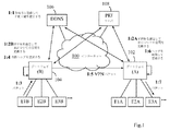
ここで、上記のことをどのようにして達成できるかの一例を、図1に示される通信シナリオを参照しながら説明する。つまり、2つの異なるローカルネットワークAおよびBのユーザ同士が、パブリックIPネットワーク100上で、この例では、インターネット上で、例えば、上記に提示した理由のために対向ネットワーク内のデバイス間のデータパケットの「安全な」通信を可能にするため、ネットワーク間にVPNトンネルを設定することに同意していると仮定する。
Here, an example of how the above can be achieved will be described with reference to the communication scenario shown in FIG. In other words, users of two different local networks A and B can exchange data packets between devices in the opposite network on the
図1では、第1のゲートウェイ102と第2のゲートウェイ104とが、それぞれ第1のネットワークAおよび第2のネットワークBにサービスを提供していることを示している。ここで、複数のデバイスE1A、E2A、E3A等は第1のネットワーク内に存在し、複数のデバイスE1B、E2B、E3B等は第2のネットワーク内に存在する。内部の通信用にプライベートアドレス空間が各ローカルネットワーク内で使用されるが、一般に、そのようなアドレス空間は多数のローカルネットワーク内で広範に再使用されるため、アドレス空間が相互に重複する可能性がある。さらに、各ゲートウェイ102および104は、以下に説明する方法でプライベートネットワークアドレスを変換する機能を含むと仮定する。ここで、この機能は、「NAT」(Network Address Tramslation)機能と呼ぶことがある。
FIG. 1 shows that the
VPNトンネルを確立する前に、ゲートウェイ102および104はそれぞれ、最初にそれらの名前とパブリックIPアドレスとをDNS(Domain Name Server)に登録することになる。この場合は、動的IPアドレスと固定IPアドレスとを両方とも可能にするDDNS106(Dynamic DNS)に登録することになる。ここで、これは、典型的にはゲートウェイを起動する時に行われる。また、ゲートウェイ102および104は、それらの公開鍵と秘密鍵または暗号化用の証明書を、周知のPKI(Public Key Infrastructure)メカニズムに従って生成し、そして、公開鍵がPKIサーバ108に登録される。第1のステップ1:1は、図中の双方向矢印によって示されるように、両方のゲートウェイによって行われるDNS登録と鍵の確立とを略示する。従って、このステップは、通常の手順に従って実行することができ、ここでは、これ以上、この例を説明するために記述する必要はない。
Before establishing the VPN tunnel, each of the
その後のステップ1:2Aと1:2Bとは、ゲートウェイ間でVPNトンネルが確立されることを示し、また、各ゲートウェイが、自分自身のデバイスについて内部的に使用されるIPアドレス空間との重複を避けるように選択されている、対向ローカルネットワーク内のデバイスのためのIPアドレス空間を定義することを示している。従って、ゲートウェイ102は、ステップ1:2AでネットワークBのデバイス用のIPアドレス空間を定義し、一方、ゲートウェイ104は、ステップ1:2BでネットワークAのデバイス用のIPアドレス空間を定義する。VPNを確立することには、特に、各ゲートウェイの中に、上記で定義されたIPアドレス空間を、または少なくともその識別情報を、対向ゲートウェイの名前と関連のパブリックIPアドレスと共に記憶することが含まれる。ここで、それらは、DDNS106で利用可能であり、かつ検索される。
Subsequent steps 1: 2A and 1: 2B indicate that a VPN tunnel is established between the gateways, and that each gateway overlaps the IP address space used internally for its own device. Fig. 4 illustrates defining an IP address space for devices in the opposing local network that are selected to be avoided. Thus,
このようにして、あるローカルネットワーク内のゲートウェイが、他のローカルネットワークのゲートウェイとの複数のVPNトンネルを確立することができ、少なくともトンネル識別情報と、そのネットワーク内で各対向ローカルネットワークについて使用される、重複しないIPアドレス空間とを含む変換テーブル等を、ゲートウェイの中に作成することができる。従って、これらのIPアドレス空間はいずれも、そのネットワーク内で使用される他のいかなるIPアドレス空間とも重複しないはずである。任意の対向ローカルネットワークの中のデバイスから着信データパケットが受信される度に、着信VPNトンネルが識別され、そして、変換テーブルの中のそのトンネルに関連するIPアドレス空間から取り込まれるローカルIPアドレスが、送信側ネットワークのデバイスについて受信側ネットワーク内で使用される。ここで、これについては、以下でより詳述する。 In this way, a gateway in one local network can establish multiple VPN tunnels with gateways in other local networks, and is used for at least the tunnel identification information and each opposing local network within that network. A conversion table including a non-overlapping IP address space can be created in the gateway. Therefore, none of these IP address spaces should overlap with any other IP address space used in the network. Each time an incoming data packet is received from a device in any opposing local network, the incoming VPN tunnel is identified and the local IP address taken from the IP address space associated with that tunnel in the translation table is Used in the receiving network for devices in the sending network. This will be described in more detail below.
上記のように、変換テーブルは、各トンネル識別情報に関連付けられている、定義されたIPアドレス空間の識別表示を含んでもよい。例えば、IPアドレス空間が、IPv4(IP第4バージョン)に基づくアドレスを含む場合、各IPアドレスの第2または第3オクテットの中の一意の数が、対応する対向ローカルネットワークを表すために、割り当てられてもよい。その結果、その一意の数が、変換テーブルの中のネットワークを識別するために十分である場合もある。例えば、10.0.0.0/24というアドレス空間が本ネットワークの中のデバイスについて使用される場合、ネットワーク識別表示として第3オクテットを使用して、例示的なIPアドレス空間、すなわち、10.0.1.0/24、10.0.2.0/24、10.0.3.0/24等が、異なる対向ネットワークについて定義されてもよい。しかしながら、他のアドレス指定スキームおよび適切なネットワーク識別表示が、同様に使用されてもよいのであって、本発明は、上記の例に限定されるものではない。 As described above, the translation table may include an identification indication of the defined IP address space associated with each tunnel identification information. For example, if the IP address space includes an address based on IPv4 (IP 4th version), a unique number in the second or third octet of each IP address is assigned to represent the corresponding opposing local network. May be. As a result, the unique number may be sufficient to identify the network in the translation table. For example, if an address space of 10.0.0.0/24 is used for devices in the network, the third octet is used as the network identification, and an exemplary IP address space, i.e. 0.1.0 / 24, 10.0.2.0/24, 10.0.3.0/24, etc. may be defined for different opposing networks. However, other addressing schemes and appropriate network identification may be used as well, and the invention is not limited to the above examples.
また、それによって、発信パケットのために正確なVPNトンネルを、そのパケットの内部宛先アドレスの中の一意の数に基づいて判定することができ、次いで、その結果、そのパケットを、判定されたVPNトンネルを介して送信することができる。送信側デバイスは、対向ローカルネットワーク内のデバイスについて定義されたIPアドレス空間の知識を得ることができ、かつ、パケット内の宛先アドレスは、受信側デバイスに割り当てられたものであると仮定する。 It can also determine the exact VPN tunnel for the outgoing packet based on the unique number in the packet's internal destination address, which in turn results in the packet being determined VPN Can be sent through a tunnel. Assume that the sending device can gain knowledge of the IP address space defined for the devices in the opposing local network, and the destination address in the packet is that assigned to the receiving device.
図1に戻ると、データパケットが、ローカルネットワークBの中の1つのデバイスE1Bから、ローカルネットワークAの中の別のデバイスE3Aに向けて送信される。パケットは、ローカル宛先IPアドレスとソースIPアドレスとを有する内部ヘッダを有しており、次のステップ1:3で、最初にゲートウェイ104で受信される。内部ヘッダでは、E3AとE1Bとの宛先IPアドレスおよびソースIPアドレスはそれぞれ、送信側ネットワークBで使用されているアドレスであるが、受信側ネットワークAでは使用されていない。従って、受信側ネットワークAの中で一義的なアドレス指定を行うには、これらのアドレスの変換が必要であり、それは、受信側ネットワークAのゲートウェイ102によって行われることになる。従って、これによって、パケットが意図されている宛先デバイスに到達することが保証されることになる。
Returning to FIG. 1, a data packet is transmitted from one device E1B in the local network B towards another device E3A in the local network A. The packet has an internal header with a local destination IP address and a source IP address and is received at the
パケットを送信する前に、ゲートウェイ104は、他の識別スキームも可能であるけれども、内部ヘッダの中のプライベート宛先IPアドレスに基づいて、例えば、上記の方法で、第2または第3オクテットから、ネットワークAとのVPNトンネルを識別し、そして、次のステップ1:4で、ゲートウェイ102および104のパブリックIPアドレスをそれぞれ宛先IPアドレスおよびソースIPアドレスとして有する外部ヘッダを追加する。次いで、パケットが、次のステップ1:5で、パブリックIPネットワーク100によってネットワークAのゲートウェイ102へ送信される。次いで、外部ヘッダの中のパブリック宛先IPアドレスを、パケットを従来の方法でパブリックIPネットワーク100を経由してゲートウェイ102へとルーティングするために使用することができる。
Prior to sending the packet, the
データパケットを受信する場合、ゲートウェイ102は、その目的を満足する外部ヘッダを削除し、他方、送信側ネットワークを、パケットを送信するために使用されるVPNトンネルから推定することができる。ここで、覚えておくべきことは、受信されるパケットは、受信側ネットワークAではなくて送信側ネットワークBの中で有効であったプライベート宛先アドレスとソースアドレスとを含むことである。従って、ゲートウェイ102は、次のステップ1:6で、受信側ネットワークAで使用されるアドレスへと変換することによって、パケットの内部ヘッダの中の宛先アドレスとソースアドレスとを変更する。
When receiving a data packet, the
詳細には、宛先アドレスは、デバイスE3AについてネットワークA内で使用される宛先アドレスへと変更され、そして、ソースアドレスは、デバイスE1BについてネットワークA内で使用される選択されたアドレス空間の内部ソースアドレスへと変更され、後者のアドレスは、従前にステップ1:2AでネットワークB内のデバイスについてゲートウェイ102によって定義された内部IPアドレス空間から取り込まれる。後者のアドレスは、VPNトンネルの確立の間に、他のデバイスのアドレス割当に従って、デバイスE1Bに割り当てられているものであり、この情報は、着信パケットのためのアドレス変換を可能にするため、各ゲートウェイ102および104に記憶されているものである。アドレス割当は、所定のスキームに従って、例えば、カウンタが、第1の対向ローカルネットワークへの第3オクテットにおいて「1」を割り当て、第2の対向ローカルネットワークへの第3オクテットにおいて「2」を割り当て、以下同様にして割り当てることによって実行されても良い。また、アドレス割当は、固定であっても動的であってもよい。
Specifically, the destination address is changed to the destination address used in network A for device E3A, and the source address is the internal source address of the selected address space used in network A for device E1B. The latter address is taken from the internal IP address space previously defined by the
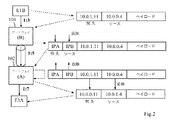
図2は、上記で論じたデータパケットのヘッダが、図1について説明されるパケット送信の様々な段階でどのように構成されうるかの一例をより詳細に図示する。従って、図2の左側は、送信側デバイスE1Bと、それぞれネットワークBのゲートウェイ104およびネットワークAのゲートウェイ102と、そして、受信側デバイスE3Aとを示している。
FIG. 2 illustrates in more detail an example of how the header of the data packet discussed above may be configured at various stages of the packet transmission described with respect to FIG. Thus, the left side of FIG. 2 shows the sending device E1B, the
この例では、ネットワークBは、自分自身のデバイスについてアドレス空間10.0.0.0/24を使用し、そして、アドレス空間10.0.1.0/24は、対向ネットワークAのデバイスについて定義されている。従って、これらのアドレス空間における第3オクテットは、デバイスのネットワークを示し、すなわち、ネットワークBでは、「0」はネットワークBを示し、「1」はネットワークAを示している。また、反対側では、ネットワークAは、自分自身のデバイスについてアドレス空間10.0.0.0/24を使用し、そして、アドレス空間10.0.1.0/24は、同様に、対向ネットワークBのデバイスについて定義されている。従って、ネットワークAでは、ネットワークBでの状況とは逆に、「0」はネットワークAを示し、「1」はネットワークBを示している。 In this example, network B uses address space 10.0.0.0/24 for its own device, and address space 10.0.1.0/24 is defined for the device in opposing network A. Has been. Thus, the third octet in these address spaces indicates the network of devices, ie, in network B, “0” indicates network B and “1” indicates network A. Also on the other side, network A uses address space 10.0.0.0/24 for its own device, and address space 10.0.1.0/24 is also the opposite network. The device B is defined. Accordingly, in the network A, contrary to the situation in the network B, “0” indicates the network A and “1” indicates the network B.
デバイスE1Bから送信されるパケットが、上記のステップ1:3に従って最初にゲートウェイ104で受信される場合、パケットは、デバイスE3Aについて有効な宛先アドレス10.0.1.11と、デバイスE1Bについて有効なソースアドレス10.0.0.4とを有する、ネットワークB内で有効な内部ヘッダを有する。上記のステップ1:4に従って、ゲートウェイ104は、ゲートウェイ102のパブリック宛先アドレスIPAとゲートウェイ104のパブリックソースアドレスIPBとを使って、外部ヘッダを追加する。次いで、ゲートウェイ104は、ネットワークAを指し示す「1」というネットワーク指標から正確なVPNトンネルを識別し、そして、上記のステップ1:5に従って、トンネルを介してパケットをゲートウェイ102へ送信する。
If a packet sent from device E1B is first received at
パケットを受信しているゲートウェイ102は、次いで、外部ヘッダを削除し、そして、プライベート宛先アドレスを10.0.0.11へ、かつ、ソースアドレスを10.0.1.4へと変換することによって、内部ヘッダを変更する。ここで、それらは、ネットワークAにおいてそれぞれデバイスE1BとE3Aとについて有効である。内部ヘッダが修正されたパケットは、次いで、最終的には、上記のステップ1:7に従って、デバイスE3Aへ転送される。ゆえに、上記のように、ネットワークAおよびBにおいて重複するアドレス空間が使用される場合であっても、内部ヘッダの中の宛先アドレスおよびソースアドレスは、それぞれのデバイスを適切に、かつ、受信側ネットワークAにおける混乱のリスクを伴わずに、識別することになる。
The
また、デバイスE3Aは、受信したソースアドレスを宛先アドレスとして、かつ、自分自身のプライベートアドレスをソースアドレスとして使用して、デバイスE1Bへのリプライとしてデータパケットを送信することができる。ここで、どちらのアドレスもネットワークAでは有効である。その場合、上記の手順は、逆方向に繰り返されるでことになり、従って、受信側ゲートウェイ104は、宛先アドレスとソースアドレスとをネットワークBで有効なもの変換戻すことによって、すなわち、10.0.0.4(ソース)と10.0.1.11(宛先)とに変換することによって、内部ヘッダを変更することになる。
Further, the device E3A can transmit a data packet as a reply to the device E1B using the received source address as the destination address and its own private address as the source address. Here, both addresses are valid in the network A. In that case, the above procedure would be repeated in the reverse direction, so that the receiving
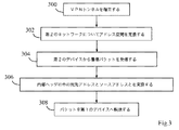
ここで、第1のローカルネットワークのゲートウェイによって実行される、第1のローカルネットワーク内の第1の通信デバイスと対向する第2のローカルネットワーク内の第2の通信デバイスとの間でデータパケットを通信するための手順について、図3のフローチャートを参照しながら説明する。第1のローカルネットワークおよび第2のローカルネットワーク内で自身のそれぞれのデバイスについて使用されるプライベートIPアドレスが、例えば、典型的には、複数のローカルネットワーク内で再使用されるアドレス空間に属することによって、相互に重複する可能性があると仮定する。 Here, the data packet is communicated between the first communication device in the first local network and the second communication device in the second local network that is executed by the gateway of the first local network. The procedure for this will be described with reference to the flowchart of FIG. The private IP addresses used for their respective devices in the first local network and the second local network, for example, typically belong to an address space that is reused in multiple local networks Suppose there is a possibility of overlapping each other.
第1のステップ300で、対向する第2のローカルネットワーク内のゲートウェイとのVPNトンネルが確立される。これには、特に、DDNSから利用可能であって、かつ、検索することもできる、対向ゲートウェイの名前と関連のパブリックIPアドレスとを記憶することが含まれる。第2のステップ302で、プライベートIPアドレス空間が、第1のネットワーク内で自身のデバイスについて使用されるプライベートIPアドレス空間とは重複しないように選択されている、第2のネットワークについて定義される。さらに、対向する第2のゲートウェイが、同様に、重複しないプライベートIPアドレス空間を第1のネットワークについても定義すると仮定する。ステップ300および302は、基本的に、ステップ1:2Aと1:2Bについて上述したように実行することができる。
In a
次のステップ304では、後の何らかの時点で着信データパケットがVPNトンネルを介して受信される。ここで、そのパケットは、第2のデバイスから送信されているものであって、それぞれ第1のデバイスおよび第2のデバイスについて第2のネットワーク内で使用される宛先アドレスとソースアドレスとを有する内部ヘッダを有する。次いで、次のステップ306で、第1のゲートウェイが、内部ヘッダの中の宛先アドレスとソースアドレスとを、それぞれ第1のデバイスと第2のデバイスについて第1のネットワーク内で使用される宛先アドレスとソースアドレスとに変更する。最後に示されるステップ308で、パケットは、内部ヘッダを修正された上で、第1のデバイスへ転送される。次いで、第1のデバイスは、受信したソースアドレスを宛先アドレスとして使用して、データパケットを第2のデバイスへ送信することによって、応答することができる。ここで、そのアドレスは、上記の方法で、受信側の第1のゲートウェイによって再び変換されることになる。
In the
ここで、第1のゲートウェイ400における装置について、図4のブロック図を参照しながら、より詳細に説明する。ゲートウェイ400は、第1のローカルネットワークにサービスを提供していて、そして、第1のローカルネットワーク内の第1の通信デバイスと、第2のゲートウェイによってサービスが提供される第2のローカルネットワーク内の第2の通信デバイスとの間で、データパケットを通信できると仮定する。また、第1のゲートウェイと第2のゲートウェイとの間でVPNトンネルが確立されていて、パブリックIPアドレスが各ゲートウェイに割り当てられており、そして、各ローカルネットワーク内のデバイスについて、重複する可能性のあるプライベートIPアドレスが使用されていると仮定する。
Here, the device in the
ゲートウェイ400は、第2のローカルネットワーク内のデバイスについて第1のローカルネットワーク内で使用されることになる、選択された内部IPアドレス空間を定義するように構成されているIPアドレス定義手段400aを備える。選択された内部IPアドレス空間は、第1のローカルネットワーク内のデバイスについて第1のローカルネットワーク内で使用される内部IPアドレス空間とは別であり、すなわち、重複していない。
The
ゲートウェイ400は、さらに、着信データパケットPを第2のデバイスから受信するように構成されている受信手段400bを備える。着信パケットPは、外部IPヘッダおよび内部IPヘッダを有しており、後者は、第1のデバイスについて第2のローカルネットワーク内で使用される内部宛先アドレスと、第2のデバイスについて第2のローカルネットワーク内で使用される内部ソースアドレスとを含んでいる。
The
また、ゲートウェイ400は、内部宛先アドレスを、第1のデバイスについて第1のローカルネットワーク内で使用される内部宛先アドレスに変更し、そして、内部ソースアドレスを、第2のデバイスについて第1のローカルネットワーク内で使用され、かつ、選択された内部IPアドレス空間の中にある、選択されたアドレス空間の内部ソースアドレスに変更するように構成されている、IPアドレス変更手段400cを備える。また、IPアドレス変更手段400cは、受信したパケットから外部IPヘッダを削除するように構成されている。
The
また、ゲートウェイ400は、着信パケットP’を、変更された内部宛先アドレスおよびソースアドレスを含む、修正された内部IPヘッダを使って第2のデバイスに転送するように構成されている転送手段400dを備える。それによって、パケットヘッダの中のアドレスは、第2のローカルネットワーク内で有効な他のデバイスの任意のアドレスとも別であって、混同され得ない。
The
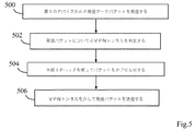
ここまでは、基本的に、データパケット送信の受信側で何が行われるかについて、例えば、図1のネットワークAのゲートウェイ102における手順と機能とについて、図3のフローチャートによって説明している。次に、図5のフローチャートを参照しながら、データパケット送信の送信側のゲートウェイによって何が行われるかについても、例えば、図1のネットワークBのゲートウェイ104における手順と機能とについて、説明する。図3の場合と同一の状況を使用して、対向する第2のネットワーク内の第2のデバイスに向けられている第1のデバイスからの発信データパケットを受信する場合、以下のさらなる手順が、第1のゲートウェイによって実行されてもよい。
So far, basically, what is performed on the receiving side of the data packet transmission, for example, the procedure and function in the
第1のステップ500は、従って、第1のデバイスから到来する発信データパケットが受信されることを示している。この発信パケットは、第2のデバイスについて第1のローカルネットワーク内で使用される内部宛先アドレスと、第1のデバイスについて第1のローカルネットワーク内で使用される内部ソースアドレスとを含む内部IPヘッダを有する。次のステップ502では、発信パケットについて、正確なVPNトンネルが、内部宛先アドレスに基づいて判定される。例えば、使用されるIPアドレス空間が、IPv4ベースのアドレスを含んでいる場合、対応する対向ローカルネットワークを表すために、各IPアドレスの第2または第3オクテットに一意の番号を割り当てることができ、そうすれば、正確なVPNトンネルが、その番号から判定される。
The
次のステップ504で、パケットが、パブリックIPネットワーク上でのルーティングを可能にする、それぞれ外部宛先アドレスおよびソースアドレスとして第1のゲートウェイおよび第2のゲートウェイのパブリックIPアドレスを含む外部IPヘッダを使ってカプセル化される。最後のステップ506で、発信パケットが、判定されたVPNトンネルを介してパブリックIPネットワーク上で第2のゲートウェイへ送信される。
In a
第1のローカルネットワークと複数の対向ローカルネットワークとの間でVPNトンネルを確立することは可能である。その場合、各対向ネットワーク内のデバイスについて第1のローカルネットワーク内で使用されることになる、選択された内部IPアドレス空間が、各対向ネットワークについて定義される。そして、選択された各IPアドレス空間は、第1のローカルネットワーク内で使用される任意の他の内部IPアドレス空間とも別であり、すなわち、重複しないはずである。 It is possible to establish a VPN tunnel between the first local network and multiple opposing local networks. In that case, a selected internal IP address space to be used in the first local network for the devices in each opposing network is defined for each opposing network. Each selected IP address space is then separate from any other internal IP address space used in the first local network, i.e., should not overlap.
さらに、対応する各対向ローカルネットワークを表すために、各IPアドレスの第2または第3オクテットに一意の番号を割り当てることができる。その場合、各発信パケットについて、発信パケットの中の内部宛先アドレスにおけるその一意の番号に基づいて正確なVPNトンネルを判定することができ、次いで、パケットは、判定されたVPNトンネルを介して送信されることになる。さらに、VPNトンネルを確立することには、各ローカルネットワークのゲートウェイに、DNSに登録されている名前と各対向ゲートウェイの対応する公開PKI鍵とを追加することが含まれる。 In addition, a unique number can be assigned to the second or third octet of each IP address to represent each corresponding opposing local network. In that case, for each outgoing packet, the exact VPN tunnel can be determined based on its unique number at the internal destination address in the outgoing packet, and then the packet is sent over the determined VPN tunnel. Will be. Further, establishing a VPN tunnel includes adding a name registered in the DNS and the corresponding public PKI key of each opposing gateway to each local network gateway.
さらに、図4に示される実施形態に従って、信頼される当事者(パーティ群)が含まれた信頼リスト400eを、第1のゲートウェイ400内で第1のローカルネットワークについて作成することができる。候補ネットワーク402のゲートウェイとのVPNトンネルを確立するためのリクエストの類が受信される場合、候補ローカルネットワークが信頼リスト400eの中に存在する第1のユーザと関連付けられている場合、VPNトンネルの確立が許可されてもよい。さらに、ゲートウェイ400は、候補ローカルネットワーク402が第1のパーティの信頼リストの中に存在する第2のユーザと関連付けられていることによって信頼リストの中の第1のパーティと間接的に関連付けられている場合、VPNトンネルの確立が許可されるように構成されてもよい。さらに、ゲートウェイ400は、第1のローカルネットワークについて承認される所定数の信頼性レベルに依存して、VPNトンネルの確立が許可されるように構成されてもよい。
Further, according to the embodiment shown in FIG. 4, a trust list 400e including trusted parties (party groups) can be created in the
上記のように、候補ローカルネットワーク402は、候補ローカルネットワークからのVPNトンネルリクエストRに応じて、信頼リスト400eに基づいて、VPNトンネルの確立について評価されてもよい。さらに、ゲートウェイ400は、2つのローカルネットワーク間で確立されたVPNトンネルが、いずれかのネットワークに関連付けられている信頼リストが、そのVPNトンネルを不適格とみなすように修正される場合、自動的に終了されるように構成されてもよい。
As described above, the candidate
ここで、VPNトンネルリクエストのために第1のゲートウェイにおいて上記の方法で信頼リストを使用するための例示的な手順について、図6のフローチャートを参照しながら簡単に説明する。まず、最初のステップ600によって略示されるように、信頼されたパーティユーザを含む信頼リストが、第1のローカルネットワークについて作成される。次のステップ602に従って、ある時点で、候補ネットワーク内のゲートウェイとのVPNトンネルを確立するためのリクエストが受信される場合、次のステップ604で、候補ネットワークが、作成された信頼リストに基づいて評価される。
An exemplary procedure for using a trust list in the above manner at the first gateway for a VPN tunnel request will now be briefly described with reference to the flowchart of FIG. First, as outlined by the
次いで、リクエストされたVPNトンネルが許可されるかどうかが、ステップ606で判定される。ここでは、例えば、すでに信頼されている当事者(パーティ群)の信頼リストの複数のレベルを考慮して、上記のように、信頼リストから導出することができる。許可される場合、最後のステップ608で示されるように、VPNトンネルが確立され、データパケットを、上記の記述に従って通信することができる。信頼リストがVPNトンネルを許可しない場合、ステップ610で、リクエストは拒否されるか、または単純に無視される。
It is then determined at
さらに図4に示されるように、上記のゲートウェイ400の中の機能性ユニットが、第1のゲートウェイ400上で実行される場合には、第1のゲートウェイの上記の機能群とステップ群とを第1のゲートウェイに実行させるコード手段を備える、コンピュータプログラム404のプログラムモジュールとして実装することができる。この実施形態では、コンピュータプログラム404は、コンピュータプログラムが記憶されているコンピュータ可読媒体を含むコンピュータプログラム製品406によって搬送される。
Further, as shown in FIG. 4, when the functional unit in the
コンピュータプログラム404のプログラムモジュールは、少なくとも、アドレス空間定義モジュール404aとアドレス変更モジュール404bとを含んでいる。アドレス空間定義モジュール404aは、第2のローカルネットワーク内のデバイスについて第1のローカルネットワーク内で使用されることになる、選択された内部IPアドレス空間を定義することができ、この選択されたIPアドレス空間は、第1のローカルネットワーク内のデバイスについて第1のローカルネットワーク内で使用される内部IPアドレス空間とは別であり、すなわち、重複していない。
The program modules of the
アドレス変更モジュール404bは、第1のデバイスについて第2のローカルネットワーク内で使用される内部宛先アドレスと第2のデバイスについて第2のローカルネットワーク内で使用される内部ソースアドレスとを含む内部IPヘッダを有する着信パケットを、第2のデバイスからVPNトンネルを介して受信する場合に、内部宛先アドレスを、第1のデバイスについて第1のローカルネットワーク内で使用される内部宛先アドレスに変更することと、内部ソースアドレスを、第2のデバイスについて第1のローカルネットワーク内で使用される選択されたアドレス空間の内部ソースアドレスであって、選択された内部IPアドレス空間の中にある内部ソースアドレスに変更することとができる。次いで、着信パケットが、変更された宛先アドレスとソースアドレスとを含む修正された内部IPヘッダを使って、第1のデバイスに転送される。
The
また、コンピュータプログラム404およびコンピュータプログラム製品406のコード手段は、第1のゲートウェイに、下記の機能群を実行させてもよい。
Further, the code means of the
着信パケットが、第1のゲートウェイのパブリックIPアドレスおよび第2のゲートウェイのパブリックIPアドレスをそれぞれ外部宛先アドレスおよび外部ソースアドレスとして含む外部IPヘッダを有する場合、コード手段が、第1のゲートウェイに着信パケットから外部IPヘッダを削除させてもよい。 If the incoming packet has an external IP header that includes the public IP address of the first gateway and the public IP address of the second gateway as the external destination address and the external source address, respectively, the code means sends the incoming packet to the first gateway. The external IP header may be deleted from
また、発信データパケットが第1のデバイスから受信され、その発信パケットが、第2のデバイスについて第1のローカルネットワーク内で使用される内部宛先アドレスと、第1のデバイスについて第1のローカルネットワーク内で使用される内部ソースアドレスとを含む内部IPヘッダを有する場合、コード手段が、第1のゲートウェイに、
−それぞれ外部宛先アドレスおよび外部ソースアドレスとして、ゲートウェイのパブリックIPアドレスを含む外部IPヘッダを使ってパケットをカプセル化させ、そして
−発信パケットがVPNトンネルを介して第2のゲートウェイへ送信される前に、内部宛先アドレスに基づいて、その発信パケットについての正確なVPNトンネルを判定させる
ようにしてもよい。
Also, an outgoing data packet is received from the first device, and the outgoing packet is an internal destination address used in the first local network for the second device and in the first local network for the first device. Code means to the first gateway, having an internal IP header containing the internal source address used in
Encapsulate the packet with an external IP header containing the gateway's public IP address as the external destination address and external source address, respectively, and before the outgoing packet is sent to the second gateway via the VPN tunnel The exact VPN tunnel for the outgoing packet may be determined based on the internal destination address.
また、コード手段は、第1のゲートウェイに、第1のローカルネットワークと複数の対向ローカルネットワークとの間にVPNトンネルを確立させ、そして、各対向ネットワーク内のデバイスについて第1のネットワーク内で使用されることになる、選択された内部IPアドレス空間を、各対向ネットワークについて定義させてもよく、この選択された各IPアドレス空間は、第1のローカルネットワーク内で使用される任意の他のアドレス空間とも別であり、すなわち、重複していない。 The code means also causes the first gateway to establish a VPN tunnel between the first local network and the plurality of opposing local networks, and is used in the first network for devices in each opposing network. A selected internal IP address space that will be defined may be defined for each opposing network, and each selected IP address space may be any other address space used within the first local network. It is also different, that is, there is no overlap.
選択されたIPアドレス空間は、IPv4ベースのアドレスを含んでもよく、次いで、各IPアドレスの第2または第3オクテットの中の一意の数が、対応する対向ローカルネットワークを表すために割り当てられてもよい。また、その場合、コード手段は、第1のゲートウェイに、各発信パケットについて、発信パケットの中の内部宛先アドレスの中の一意の数に基づいて、VPNトンネルを判定させてもよく、その場合、パケットは、次いで、判定されたVPNトンネルを介して送信される。 The selected IP address space may include IPv4-based addresses, and then a unique number in the second or third octet of each IP address may be assigned to represent the corresponding opposing local network. Good. Also, in that case, the code means may cause the first gateway to determine the VPN tunnel for each outgoing packet based on a unique number in the internal destination address in the outgoing packet, The packet is then transmitted over the determined VPN tunnel.
また、コード手段は、第1のゲートウェイに、各対向ゲートウェイのDNS登録名と対応する公開PKI鍵とを追加することによって、VPNトンネルを確立させてもよい。公開PKI鍵および対応する秘密PKI鍵が、各ゲートウェイについて生成されていてもよく、公開PKI鍵は、ゲートウェイに対してアクセス可能なPKIサーバの中に記憶される。 The code means may establish the VPN tunnel by adding the DNS registration name of each opposing gateway and the corresponding public PKI key to the first gateway. A public PKI key and a corresponding secret PKI key may be generated for each gateway, and the public PKI key is stored in a PKI server accessible to the gateway.
信頼されたパーティ群が含まれた信頼リストが第1のローカルネットワークについて作成されている場合、候補ローカルネットワークが信頼リストの中に存在する第1のパーティと関連付けられている場合、コード手段は、第1のゲートウェイに、第1のローカルネットワークと候補ローカルネットワークとの間でのVPNトンネルの確立を許可させてもよい。 If a trust list containing trusted parties is created for the first local network, if the candidate local network is associated with a first party present in the trust list, the code means The first gateway may be allowed to establish a VPN tunnel between the first local network and the candidate local network.
また、コード手段は、候補ローカルネットワークが第1のパーティの信頼リストの中に存在する第2のパーティと関連付けられることによって、信頼リストの中の第1のパーティと間接的に関連付けられる場合、第1のゲートウェイに、VPNトンネルの確立を許可させてもよい。 The code means may also be configured such that if the candidate local network is indirectly associated with the first party in the trust list by being associated with a second party that is present in the first party trust list. One gateway may be allowed to establish a VPN tunnel.
また、コード手段は、第1のローカルネットワークについて許可される、所定数の信頼性レベルに依存して、第1のゲートウェイに、VPNトンネルの確立を許可させてもよい。 The code means may also allow the first gateway to allow establishment of a VPN tunnel depending on a predetermined number of reliability levels allowed for the first local network.
また、コード手段は、候補ローカルネットワークからのVPNトンネルリクエストに応じて、第1のゲートウェイに、VPNトンネルの確立について候補ローカルネットワークを評価させてもよい。 The code means may cause the first gateway to evaluate the candidate local network for establishing the VPN tunnel in response to a VPN tunnel request from the candidate local network.
また、コード手段は、いずれかのネットワークに関連付けられている信頼リストが、そのVPNトンネルを不適格とみなすように修正される場合、第1のゲートウェイに、2つのローカルネットワーク間で、確立されたVPNトンネルを自動的に終了させてもよい。 Also, the code means may be established between the two local networks at the first gateway if the trust list associated with any network is modified to consider the VPN tunnel ineligible. The VPN tunnel may be automatically terminated.
留意すべきことは、図4は、ゲートウェイ400の中の各種の例示的な機能性ユニットとプログラムモジュールとを単に論理的な意味で示しているにすぎず、他方、当業者であれば、実際には、任意の適切なソフトウェアおよびハードウェア手段を使用して自由に実装することができることである。従って、本発明は、一般に、ゲートウェイ400の図示する構造に限定されるものではない。例えば、コンピュータプログラム製品は、フラッシュメモリ、ROM(Read−Only Memory)またはEEPROM(Electrically Erasable Programmable ROM)であってもよいし、上記のコンピュータプログラムモジュールは、代替実施形態では、ゲートウェイ400の範囲内のメモリという形で、異なるコンピュータプログラム製品上に分散されてもよいだろう。
It should be noted that FIG. 4 merely shows the various exemplary functional units and program modules in
本発明について、特定の実施形態を参照して記載しているが、この記載は、一般に、発明の概念を例示することだけを意図しており、本発明の範囲を限定していると解釈されるべきではない。本発明は、添付の請求項によって定義される。 Although the invention has been described with reference to particular embodiments, this description is generally intended to be exemplary only of the concepts of the invention and is to be construed as limiting the scope of the invention. Should not. The invention is defined by the appended claims.
Claims (28)
前記第1のローカルネットワークにサービスを提供する第1のゲートウェイ(A)と、前記第2のローカルネットワークにサービスを提供する第2のゲートウェイ(B)との間にVPNトンネルを確立するステップであって、パブリックIPアドレスが前記第1のゲートウェイ(A)と前記第2のゲートウェイ(B)との各ゲートウェイに割り当てられている、ステップと、
前記第1のゲートウェイにおいて、前記第2のローカルネットワーク内のデバイスについて、前記第1のローカルネットワーク内で使用される、選択された内部IPアドレス空間を定義するステップであって、前記選択された内部IPアドレス空間は、前記第1のローカルネットワーク内のデバイスについて前記第1のローカルネットワーク内で使用される内部IPアドレス空間とは異なる、重複していないIPアドレス空間である、ステップと、
前記第1のゲートウェイにおいて、前記VPNトンネルを介して前記第2のデバイス(E1B)からの着信パケットを受信するステップであって、前記着信パケットは、前記第1のデバイスについて前記第2のローカルネットワーク内で使用される内部宛先アドレスと、前記第2のデバイスについて前記第2のローカルネットワーク内で使用される内部ソースアドレスとを含む内部IPヘッダを有する、ステップと、
前記内部宛先アドレスを、前記第1のデバイスについて前記第1のローカルネットワーク内で使用される内部宛先アドレスに変更するステップと、
前記内部ソースアドレスを、前記第2のデバイスについて前記第1のローカルネットワーク内で使用され、かつ、前記選択された内部IPアドレス空間の中にある、選択されたアドレス空間の内部ソースアドレスへと変更するステップと、
前記着信パケットを、変更された内部宛先アドレスと変更された内部ソースアドレスとを含む修正された内部IPヘッダと共に、前記第1のデバイス(E3A)に転送するステップと
を備えることを特徴とする方法。 A first communication device (E3A) in the first local network when a private IP address that may be duplicated is used for a device in the first local network and a device in the second local network ) And a second communication device (E1B) in the second local network, comprising:
Establishing a VPN tunnel between a first gateway (A) providing service to the first local network and a second gateway (B) providing service to the second local network. A public IP address is assigned to each of the first gateway (A) and the second gateway (B);
Defining, in the first gateway, a selected internal IP address space to be used in the first local network for devices in the second local network, the selected internal IP address space being used in the first local network; An IP address space is a non-overlapping IP address space that is different from an internal IP address space used in the first local network for devices in the first local network;
Receiving an incoming packet from the second device (E1B) via the VPN tunnel at the first gateway, wherein the incoming packet is the second local network for the first device; Having an internal IP header that includes an internal destination address used within and an internal source address used within the second local network for the second device;
Changing the internal destination address to an internal destination address used in the first local network for the first device;
Changing the internal source address to an internal source address of a selected address space that is used in the first local network for the second device and is within the selected internal IP address space And steps to
Forwarding the incoming packet to the first device (E3A) with a modified internal IP header that includes a modified internal destination address and a modified internal source address. .
前記外部IPヘッダは、前記第1のゲートウェイによって前記着信パケットから削除される
ことを特徴とする請求項1に記載の方法。 The incoming packet further includes an external IP header including a public IP address of the first gateway and a public IP address of the second gateway as an external destination address and an external source address, respectively.
The method of claim 1, wherein the outer IP header is deleted from the incoming packet by the first gateway.
それぞれ外部宛先アドレスと外部ソースアドレスとして、前記第1のゲートウェイのパブリックIPアドレスと前記第2のゲートウェイのパブリックIPアドレスを含む外部IPヘッダで、前記発信パケットをカプセル化するステップと、
前記内部宛先アドレスに基づいて、前記発信パケットについての正確なVPNトンネルを判定するステップと、
前記発信パケットを、前記VPNトンネルを介して前記第2のゲートウェイへ送信するステップと
を更に備えることを特徴とする請求項1または2に記載の方法。 Receiving an outgoing packet from the first device at the first gateway, the outgoing packet comprising an internal destination address used in the first local network for the second device; Having an internal IP header that includes an internal source address used in the first local network for the first device;
Encapsulating the outgoing packet with an external IP header including a public IP address of the first gateway and a public IP address of the second gateway, respectively as an external destination address and an external source address;
Determining an accurate VPN tunnel for the outgoing packet based on the internal destination address;
The method according to claim 1, further comprising: transmitting the outgoing packet to the second gateway via the VPN tunnel.
前記複数の対向ローカルネットワークそれぞれの対向ネットワーク内のデバイスについて前記第1のローカルネットワーク内で使用されることになる選択された内部IPアドレス空間が、前記それぞれの対向ネットワークについて定義され、
前記選択された内部IPアドレス空間それぞれは、前記第1のローカルネットワーク内で使用される任意の他のアドレス空間と異なる、重複していないIPアドレス空間である
ことを特徴とする請求項1乃至3のいずれか1項に記載の方法。 The VPN tunnel is established between the first local network and a plurality of opposing local networks;
A selected internal IP address space to be used in the first local network for devices in the opposing network of each of the plurality of opposing local networks is defined for the respective opposing network;
Each of the selected internal IP address spaces is a non-overlapping IP address space that is different from any other address space used in the first local network. The method of any one of these.
前記アドレス群のそれぞれの第2または第3オクテットの一意の数が、対応する前記対向ローカルネットワークを表すために割り当てられる
ことを特徴とする請求項4に記載の方法。 The selected internal IP address space includes an IPv4-based address group;
The method of claim 4, wherein a unique number of each second or third octet of the group of addresses is assigned to represent the corresponding opposing local network.
前記発信パケットは、判定されたVPNトンネルを介して送信される
ことを特徴とする請求項5に記載の方法。 For each of the outgoing packets, a VPN tunnel is determined based on the unique number in an internal destination address in the outgoing packet;
The method according to claim 5, wherein the outgoing packet is transmitted through the determined VPN tunnel.
ことを特徴とする請求項4乃至6のいずれか1項に記載の方法。 The establishment of the VPN tunnel includes adding a DNS registration name of each opposing gateway and a corresponding public PKI key to each gateway of the local network. The method of any one of these.
前記公開PKI鍵は、前記ゲートウェイがアクセス可能なPKIサーバに記憶されている
ことを特徴とする請求項7に記載の方法。 A secret PKI key corresponding to the public PKI key is generated for each gateway,
The method of claim 7, wherein the public PKI key is stored on a PKI server accessible to the gateway.
候補ローカルネットワークが、前記信頼リストの中に存在する第1のパーティと関連付けられている場合、前記第1のローカルネットワークと前記候補ローカルネットワークとの間でVPNトンネルの確立が許可される
ことを特徴とする請求項1乃至8のいずれか1項に記載の方法。 A trust list including trusted parties is created for the first local network;
When a candidate local network is associated with a first party present in the trust list, establishment of a VPN tunnel between the first local network and the candidate local network is permitted. The method according to any one of claims 1 to 8.
ことを特徴とする請求項9に記載の方法。 The candidate local network is indirectly associated with the first party in the trust list by being associated with a second party that is present in the trust list of the first party. The method of claim 9, wherein the VPN tunnel is allowed to be established.
ことを特徴とする請求項10に記載の方法。 11. The method of claim 10, wherein the VPN tunnel is allowed to be established depending on a predetermined number of trust levels approved for the first local network.
ことを特徴とする請求項9乃至11のいずれか1項に記載の方法。 The method according to any one of claims 9 to 11, wherein the candidate local network is evaluated for establishment of a VPN tunnel in response to a VPN tunnel request from the candidate local network.
ことを特徴とする請求項9乃至12のいずれか1項に記載の方法。 A VPN tunnel established between two local networks will be automatically terminated if the trust list associated with either local network is modified to consider the VPN tunnel ineligible 13. A method according to any one of claims 9 to 12, characterized in that
当該装置は、前記第1のローカルネットワーク内の第1の通信デバイス(E1A)と第2のゲートウェイ(B)によってサービスが提供される第2のローカルネットワーク内の第2の通信デバイス(E1B)との間でデータパケットを通信することができ、
前記第1のゲートウェイは、前記第1のゲートウェイと前記第2のゲートウェイとの間でVPNトンネルを確立するように構成されていて、
パブリックIPアドレスが前記第1のゲートウェイと前記第2のゲートウェイそれぞれに割り当てられていて、かつ前記第1のローカルネットワーク内のデバイスおよび前記第2のローカルネットワーク内のデバイスについて重複する可能性のあるプライベートIPアドレスが使用されており、
前記装置は、
前記第2のローカルネットワーク内のデバイスについて、前記第1のローカルネットワーク内で使用される、選択された内部IPアドレス空間を定義するように構成されているIPアドレス定義手段(400a)であって、前記選択された内部IPアドレス空間は、前記第1のローカルネットワーク内のデバイスについて前記第1のローカルネットワーク内で使用される内部IPアドレス空間とは異なる、重複していないIPアドレス空間である、IPアドレス定義手段(400a)と、
前記VPNトンネルを介して前記第2のデバイスからの着信パケットを受信するように構成されている受信手段(400b)であって、前記着信パケットは、前記第1のデバイスについて前記第2のローカルネットワーク内で使用される内部宛先アドレスと、前記第2のデバイスについて前記第2のローカルネットワーク内で使用される内部ソースアドレスとを含む内部IPヘッダを有する、受信手段(400b)と、
前記内部宛先アドレスを、前記第1のデバイスについて前記第1のローカルネットワーク内で使用される前記内部宛先アドレスに変更し、かつ前記内部ソースアドレスを、前記第2のデバイスについて前記第1のローカルネットワーク内で使用され、かつ、前記選択された内部IPアドレス空間の中にある、選択されたアドレス空間の内部ソースアドレスへと変更するように構成されているIPアドレス変更手段(400c)と、
前記着信パケットを、変更された内部宛先アドレスと変更された内部ソースアドレスとを含む修正された内部IPヘッダと共に、前記第2のデバイスに転送するように構成されている転送手段(400d)と
を備えることを特徴とする装置。 A device at a first gateway (A) for providing service to a first local network comprising:
The apparatus includes a first communication device (E1A) in the first local network and a second communication device (E1B) in a second local network that is serviced by a second gateway (B). Can communicate data packets between,
The first gateway is configured to establish a VPN tunnel between the first gateway and the second gateway;
A private IP address is assigned to each of the first gateway and the second gateway, and may be duplicated for devices in the first local network and devices in the second local network IP address is used,
The device is
IP address defining means (400a) configured to define a selected internal IP address space to be used in the first local network for devices in the second local network, The selected internal IP address space is a non-overlapping IP address space that is different from the internal IP address space used in the first local network for devices in the first local network. Address defining means (400a);
Receiving means (400b) configured to receive an incoming packet from the second device via the VPN tunnel, wherein the incoming packet is the second local network for the first device; Receiving means (400b) having an internal IP header that includes an internal destination address used within and an internal source address used within the second local network for the second device;
Changing the internal destination address to the internal destination address used in the first local network for the first device, and changing the internal source address to the first local network for the second device An IP address changing means (400c) configured to change to an internal source address of the selected address space that is used in and within the selected internal IP address space;
Forwarding means (400d) configured to forward the incoming packet to the second device with a modified internal IP header including a modified internal destination address and a modified internal source address; A device comprising:
前記IPアドレス変更手段は、更に、前記外部IPヘッダを、前記第1のゲートウェイによって前記着信パケットから削除するように構成されている
ことを特徴とする請求項14に記載の装置。 The incoming packet further includes an external IP header including a public IP address of the first gateway and a public IP address of the second gateway as an external destination address and an external source address, respectively.
The apparatus according to claim 14, wherein the IP address changing means is further configured to delete the external IP header from the incoming packet by the first gateway.
それぞれ外部宛先アドレスと外部ソースアドレスとして、前記第1のゲートウェイのパブリックIPアドレスと前記第2のゲートウェイのパブリックIPアドレスを含む外部IPヘッダで、前記発信パケットをカプセル化し、
前記内部宛先アドレスに基づいて、前記発信パケットについての正確なVPNトンネルを判定し、
前記発信パケットを、前記VPNトンネルを介して前記第2のゲートウェイへ送信する
ように更に構成されている
ことを特徴とする請求項14または15に記載の装置。 As an outgoing packet received from the first device, an internal destination address used in the first local network for the second device and used in the first local network for the first device Receiving an outgoing packet having an internal IP header including an internal source address
Encapsulating the outgoing packet with an external IP header containing the public IP address of the first gateway and the public IP address of the second gateway, respectively as an external destination address and an external source address;
Determining an exact VPN tunnel for the outgoing packet based on the internal destination address;
The apparatus according to claim 14 or 15, further configured to transmit the outgoing packet to the second gateway via the VPN tunnel.
前記複数の対向ローカルネットワークそれぞれの対向ネットワーク内のデバイスについて前記第1のローカルネットワーク内で使用されることになる選択された内部IPアドレス空間が、前記それぞれの対向ネットワークについて定義され、
前記選択された内部IPアドレス空間それぞれは、前記第1のローカルネットワーク内で使用される任意の他のアドレス空間と異なる、重複していないIPアドレス空間である
ことを特徴とする請求項14乃至16のいずれか1項に記載の装置。 The VPN tunnel is established between the first local network and a plurality of opposing local networks;
A selected internal IP address space to be used in the first local network for devices in the opposing network of each of the plurality of opposing local networks is defined for the respective opposing network;
Each of the selected internal IP address spaces is a non-overlapping IP address space that is different from any other address space used in the first local network. The apparatus of any one of these.
前記アドレス群のそれぞれの第2または第3オクテットの一意の数が、対応する対向ローカルネットワークを表すために割り当てられる
ことを特徴とする請求項17に記載の装置。 The selected internal IP address space includes an IPv4-based address group;
18. The apparatus of claim 17, wherein a unique number of each second or third octet of the address group is assigned to represent a corresponding opposing local network.
ことを特徴とする請求項14乃至18のいずれか1項に記載の装置。 Further, for each of the outgoing packets, a VPN tunnel is determined based on the unique number in the internal destination address in the outgoing packet, and the outgoing packet is transmitted through the determined VPN tunnel. The apparatus according to claim 14, wherein the apparatus is configured as follows.
ことを特徴とする請求項19に記載の装置。 The establishment of the VPN tunnel includes adding a DNS registered name and a corresponding public PKI key of each of the opposing gateways in each of the gateways of each local network. Equipment.
前記公開PKI鍵は、前記ゲートウェイがアクセス可能なPKIサーバに記憶されている
ことを特徴とする請求項20に記載の装置。 A secret PKI key corresponding to the public PKI key is generated for each gateway,
The apparatus according to claim 20, wherein the public PKI key is stored in a PKI server accessible by the gateway.
ことを特徴とする請求項14乃至21のいずれか1項に記載の装置。 If a trust list including trusted parties is created for the first local network and a candidate local network is associated with a first party that is present in the trust list, the first list The apparatus according to any one of claims 14 to 21, further configured to allow establishment of a VPN tunnel between a local network and the candidate local network.
ことを特徴とする請求項22に記載の装置。 If the candidate local network is indirectly associated with the first party in the trust list by being associated with a second party present in the trust list of the first party; 23. The apparatus of claim 22, further configured to allow establishment of the VPN tunnel.
ことを特徴とする請求項23に記載の装置。 24. The apparatus of claim 23, further configured to allow establishment of the VPN tunnel depending on a predetermined number of trust levels approved for the first local network.
ことを特徴とする請求項22乃至24のいずれか1項に記載の装置。 25. The system according to any one of claims 22 to 24, further configured to evaluate the candidate local network for establishment of a VPN tunnel in response to a VPN tunnel request from the candidate local network. apparatus.
ことを特徴とする請求項22乃至25のいずれか1項に記載の装置。 If the trust list associated with any local network has been modified to consider the VPN tunnel ineligible, the VPN tunnel further established to automatically terminate the VPN tunnel established between the two local networks. 26. The apparatus according to any one of claims 22 to 25, wherein the apparatus is configured.
前記第1のゲートウェイ(A)と前記第2のゲートウェイ(B)との間にはVPNトンネルが確立されていて、
前記第1のゲートウェイと前記第2のゲートウェイそれぞれにパブリックIPアドレスが割り当てられていて、かつ前記第1のローカルネットワーク内のデバイスおよび前記第2のローカルネットワーク内のデバイスについて重複する可能性のあるプライベートIPアドレスが使用されていて、
前記コンピュータプログラムは、前記第1のゲートウェイ上で動作する場合に前記第1のゲートウェイに、
前記第2のローカルネットワーク内のデバイスについて、前記第1のローカルネットワーク内で使用される、選択された内部IPアドレス空間を定義させるコード手段であって、前記選択された内部IPアドレス空間は、前記第1のローカルネットワーク内のデバイスについて前記第1のローカルネットワーク内で使用される内部IPアドレス空間とは異なる、重複していないIPアドレス空間である、コード手段と、
前記VPNトンネルを介して前記第2のデバイスからの着信パケットとして、前記第1のデバイスについて前記第2のローカルネットワーク内で使用される内部宛先アドレスと、前記第2のデバイスについて前記第2のローカルネットワーク内で使用される内部ソースアドレスとを含む内部IPヘッダを有する着信パケットを受信する場合に、
前記内部宛先アドレスを、前記第1のデバイスについて前記第1のローカルネットワーク内で使用される前記内部宛先アドレスに変更させるコード手段と、、
前記内部ソースアドレスを、前記第2のデバイスについて前記第1のローカルネットワーク内で使用され、かつ、前記選択された内部IPアドレス空間の中にある、選択されたアドレス空間の内部ソースアドレスへと変更させる手段とを備え、
その後、前記着信パケットは、変更された内部宛先アドレスと変更された内部ソースアドレスとを含む修正された内部IPヘッダと共に、前記第2のデバイスに転送される
ことを特徴とするコンピュータプログラム。 A second in a second local network that serves the first local network and is served by a first communication device (E1A) and a second gateway (B) in the first local network. A computer program (400e) for a first gateway (A) capable of communicating data packets with two communication devices (E3B),
A VPN tunnel is established between the first gateway (A) and the second gateway (B),
A public IP address is assigned to each of the first gateway and the second gateway, and private devices that may overlap for devices in the first local network and devices in the second local network IP address is used,
When the computer program runs on the first gateway, the computer program
Code means for defining a selected internal IP address space used in the first local network for devices in the second local network, wherein the selected internal IP address space is Code means that is a non-overlapping IP address space that is different from the internal IP address space used in the first local network for devices in the first local network;
As an incoming packet from the second device via the VPN tunnel, an internal destination address used in the second local network for the first device and the second local for the second device When receiving an incoming packet having an internal IP header including an internal source address used in the network,
Code means for changing the internal destination address to the internal destination address used in the first local network for the first device;
Changing the internal source address to an internal source address of a selected address space that is used in the first local network for the second device and is within the selected internal IP address space And means for causing
Thereafter, the incoming packet is forwarded to the second device together with a modified internal IP header including a modified internal destination address and a modified internal source address.
Applications Claiming Priority (3)
| Application Number | Priority Date | Filing Date | Title |
|---|---|---|---|
| US3819208P | 2008-03-20 | 2008-03-20 | |
| US61/038,192 | 2008-03-20 | ||
| PCT/SE2009/050292 WO2009116945A1 (en) | 2008-03-20 | 2009-03-20 | Method and apparatus for communication of data packets between local networks |
Publications (1)
| Publication Number | Publication Date |
|---|---|
| JP2011515944A true JP2011515944A (en) | 2011-05-19 |
Family
ID=41091161
Family Applications (2)
| Application Number | Title | Priority Date | Filing Date |
|---|---|---|---|
| JP2011500742A Expired - Fee Related JP5335886B2 (en) | 2008-03-20 | 2009-03-20 | Method and apparatus for communicating data packets between local networks |
| JP2011500741A Pending JP2011515944A (en) | 2008-03-20 | 2009-03-20 | Method and apparatus for data packet communication between local networks |
Family Applications Before (1)
| Application Number | Title | Priority Date | Filing Date |
|---|---|---|---|
| JP2011500742A Expired - Fee Related JP5335886B2 (en) | 2008-03-20 | 2009-03-20 | Method and apparatus for communicating data packets between local networks |
Country Status (6)
| Country | Link |
|---|---|
| US (2) | US8295285B2 (en) |
| EP (2) | EP2253124B1 (en) |
| JP (2) | JP5335886B2 (en) |
| ES (1) | ES2429121T3 (en) |
| IL (2) | IL207903A (en) |
| WO (2) | WO2009116948A1 (en) |
Cited By (4)
| Publication number | Priority date | Publication date | Assignee | Title |
|---|---|---|---|---|
| JP2011139298A (en) * | 2009-12-28 | 2011-07-14 | Nippon Telegr & Teleph Corp <Ntt> | Address determination device, address determination method, and address determination program |
| JP2013247678A (en) * | 2012-05-23 | 2013-12-09 | Gemtec Technology Co Ltd | Routing device |
| JP2017505587A (en) * | 2014-02-06 | 2017-02-16 | アクセレレイション システムズ,リミティド ライアビリティ カンパニー | System and method for providing composite secure link architecture |
| JP2019062557A (en) * | 2014-02-06 | 2019-04-18 | アクセレレイション システムズ,リミティド ライアビリティ カンパニー | Systems and methods for providing multiple secure link architecture |
Families Citing this family (101)
| Publication number | Priority date | Publication date | Assignee | Title |
|---|---|---|---|---|
| US8160255B2 (en) * | 2006-04-24 | 2012-04-17 | Cisco Technology, Inc. | System and method for encrypted group network communication with point-to-point privacy |
| US8625610B2 (en) * | 2007-10-12 | 2014-01-07 | Cisco Technology, Inc. | System and method for improving spoke to spoke communication in a computer network |
| EP2203832A4 (en) * | 2007-10-24 | 2013-01-16 | Lantronix Inc | Various methods and apparatuses for a central management station for automatic distribution of configuration information to remote devices |
| US8346961B2 (en) | 2007-12-12 | 2013-01-01 | Cisco Technology, Inc. | System and method for using routing protocol extensions for improving spoke to spoke communication in a computer network |
| US8837491B2 (en) | 2008-05-27 | 2014-09-16 | Glue Networks | Regional virtual VPN |
| KR20100040658A (en) * | 2008-10-10 | 2010-04-20 | 삼성전자주식회사 | Method and apparatus for preventing ip address conflict in remote access service of upnp network |
| US9319300B2 (en) * | 2008-12-09 | 2016-04-19 | Glue Networks, Inc. | Systems and methods for determining endpoint configurations for endpoints of a virtual private network (VPN) and deploying the configurations to the endpoints |
| US8726007B2 (en) * | 2009-03-31 | 2014-05-13 | Novell, Inc. | Techniques for packet processing with removal of IP layer routing dependencies |
| RU2011154095A (en) * | 2009-05-29 | 2013-07-10 | Телефонактиеболагет Лм Эрикссон (Пабл) | IMPROVEMENT OF PRODUCTIVITY OF THE SYSTEM OF JOINT USE OF CONTENT |
| US8687631B2 (en) * | 2009-10-16 | 2014-04-01 | Cisco Technology, Inc. | System and method for providing a translation mechanism in a network environment |
| WO2011050466A1 (en) * | 2009-10-29 | 2011-05-05 | Sierra Wireless, Inc. | Routing device and method of configuration for network name resolution of same |
| JP5357707B2 (en) * | 2009-11-11 | 2013-12-04 | 株式会社日立製作所 | Gateway device and port number assigning method |
| JP5569697B2 (en) * | 2011-03-09 | 2014-08-13 | 村田機械株式会社 | Relay server and relay communication system |
| JP5452527B2 (en) * | 2011-03-11 | 2014-03-26 | エヌ・ティ・ティ・コムウェア株式会社 | Address management device, address management method, and address management program |
| JP5552460B2 (en) * | 2011-04-13 | 2014-07-16 | 日本電信電話株式会社 | Inter-base connection system, inter-base connection method, address conversion information generation apparatus, address conversion information generation method, and program |
| CN102333022B (en) * | 2011-05-31 | 2014-01-15 | 广东省电力调度中心 | Method for interacting cross-safety protection region information in power communication network and protection system |
| CN103748861B (en) * | 2011-07-08 | 2017-07-11 | 威尔耐特斯公司 | For the system and method for Dynamic VPN address distribution |
| CN103959720B (en) | 2011-11-30 | 2017-04-26 | 村田机械株式会社 | Relay server device and relay communication system |
| US10044582B2 (en) * | 2012-01-28 | 2018-08-07 | A10 Networks, Inc. | Generating secure name records |
| US8954964B2 (en) * | 2012-02-27 | 2015-02-10 | Ca, Inc. | System and method for isolated virtual image and appliance communication within a cloud environment |
| US8930493B2 (en) | 2012-03-20 | 2015-01-06 | International Business Machines Corporation | Inter-domain replication of service information |
| CN104901943A (en) * | 2012-03-31 | 2015-09-09 | 北京奇虎科技有限公司 | Method and system for accessing website |
| EP3920514A1 (en) * | 2013-01-02 | 2021-12-08 | E^NAT Technologies, LLC | Systems and methods for providing a renat communications environment |
| US9276847B2 (en) | 2013-01-02 | 2016-03-01 | Acceleration Systems, LLC | Systems and methods for providing a ReNAT virtual private network |
| US9760528B1 (en) | 2013-03-14 | 2017-09-12 | Glue Networks, Inc. | Methods and systems for creating a network |
| US9722918B2 (en) | 2013-03-15 | 2017-08-01 | A10 Networks, Inc. | System and method for customizing the identification of application or content type |
| US9928082B1 (en) | 2013-03-19 | 2018-03-27 | Gluware, Inc. | Methods and systems for remote device configuration |
| WO2014156009A1 (en) * | 2013-03-26 | 2014-10-02 | Kddi株式会社 | Transfer device |
| CN104521220B (en) | 2013-07-12 | 2017-06-20 | 华为技术有限公司 | Message processing method and equipment |
| US9952885B2 (en) | 2013-08-14 | 2018-04-24 | Nicira, Inc. | Generation of configuration files for a DHCP module executing within a virtualized container |
| US9887960B2 (en) | 2013-08-14 | 2018-02-06 | Nicira, Inc. | Providing services for logical networks |
| US9577845B2 (en) | 2013-09-04 | 2017-02-21 | Nicira, Inc. | Multiple active L3 gateways for logical networks |
| US9503371B2 (en) | 2013-09-04 | 2016-11-22 | Nicira, Inc. | High availability L3 gateways for logical networks |
| CN105658377A (en) * | 2013-10-04 | 2016-06-08 | 福吉米株式会社 | Polishing device and polishing method |
| US10063458B2 (en) | 2013-10-13 | 2018-08-28 | Nicira, Inc. | Asymmetric connection with external networks |
| US9225597B2 (en) | 2014-03-14 | 2015-12-29 | Nicira, Inc. | Managed gateways peering with external router to attract ingress packets |
| US9419855B2 (en) | 2014-03-14 | 2016-08-16 | Nicira, Inc. | Static routes for logical routers |
| US9590901B2 (en) | 2014-03-14 | 2017-03-07 | Nicira, Inc. | Route advertisement by managed gateways |
| US9647883B2 (en) | 2014-03-21 | 2017-05-09 | Nicria, Inc. | Multiple levels of logical routers |
| US9338091B2 (en) | 2014-03-27 | 2016-05-10 | Nicira, Inc. | Procedures for efficient cloud service access in a system with multiple tenant logical networks |
| US9794186B2 (en) | 2014-03-27 | 2017-10-17 | Nicira, Inc. | Distributed network address translation for efficient cloud service access |
| US9825854B2 (en) * | 2014-03-27 | 2017-11-21 | Nicira, Inc. | Host architecture for efficient cloud service access |
| WO2015147943A1 (en) * | 2014-03-27 | 2015-10-01 | Nicira, Inc. | Distributed network address translation for cloud service access |
| US9906422B2 (en) | 2014-05-16 | 2018-02-27 | A10 Networks, Inc. | Distributed system to determine a server's health |
| US11533255B2 (en) | 2014-11-14 | 2022-12-20 | Nicira, Inc. | Stateful services on stateless clustered edge |
| US9866473B2 (en) | 2014-11-14 | 2018-01-09 | Nicira, Inc. | Stateful services on stateless clustered edge |
| US10044617B2 (en) | 2014-11-14 | 2018-08-07 | Nicira, Inc. | Stateful services on stateless clustered edge |
| US9876714B2 (en) | 2014-11-14 | 2018-01-23 | Nicira, Inc. | Stateful services on stateless clustered edge |
| US10129180B2 (en) | 2015-01-30 | 2018-11-13 | Nicira, Inc. | Transit logical switch within logical router |
| US9785412B1 (en) | 2015-02-27 | 2017-10-10 | Glue Networks, Inc. | Methods and systems for object-oriented modeling of networks |
| US10038628B2 (en) | 2015-04-04 | 2018-07-31 | Nicira, Inc. | Route server mode for dynamic routing between logical and physical networks |
| CN107736077B (en) * | 2015-07-06 | 2021-10-22 | 艾可慕株式会社 | Relay device, communication packet relay method, and voice communication system |
| US10129142B2 (en) | 2015-08-11 | 2018-11-13 | Nicira, Inc. | Route configuration for logical router |
| US10075363B2 (en) | 2015-08-31 | 2018-09-11 | Nicira, Inc. | Authorization for advertised routes among logical routers |
| US9787581B2 (en) | 2015-09-21 | 2017-10-10 | A10 Networks, Inc. | Secure data flow open information analytics |
| US10095535B2 (en) | 2015-10-31 | 2018-10-09 | Nicira, Inc. | Static route types for logical routers |
| CN105681486B (en) * | 2016-01-15 | 2018-11-23 | 华洋通信科技股份有限公司 | A kind of across broadcast domain data communications method of XinIP |
| EP3223494A1 (en) * | 2016-03-21 | 2017-09-27 | Thomson Licensing | Method and apparatus for interconnection between networks |
| US10333849B2 (en) | 2016-04-28 | 2019-06-25 | Nicira, Inc. | Automatic configuration of logical routers on edge nodes |
| US10841273B2 (en) | 2016-04-29 | 2020-11-17 | Nicira, Inc. | Implementing logical DHCP servers in logical networks |
| US10484515B2 (en) | 2016-04-29 | 2019-11-19 | Nicira, Inc. | Implementing logical metadata proxy servers in logical networks |
| US10091161B2 (en) | 2016-04-30 | 2018-10-02 | Nicira, Inc. | Assignment of router ID for logical routers |
| US10153973B2 (en) | 2016-06-29 | 2018-12-11 | Nicira, Inc. | Installation of routing tables for logical router in route server mode |
| US10560320B2 (en) | 2016-06-29 | 2020-02-11 | Nicira, Inc. | Ranking of gateways in cluster |
| US10812348B2 (en) | 2016-07-15 | 2020-10-20 | A10 Networks, Inc. | Automatic capture of network data for a detected anomaly |
| US10341118B2 (en) | 2016-08-01 | 2019-07-02 | A10 Networks, Inc. | SSL gateway with integrated hardware security module |
| US10454758B2 (en) | 2016-08-31 | 2019-10-22 | Nicira, Inc. | Edge node cluster network redundancy and fast convergence using an underlay anycast VTEP IP |
| US10341236B2 (en) | 2016-09-30 | 2019-07-02 | Nicira, Inc. | Anycast edge service gateways |
| US10382562B2 (en) | 2016-11-04 | 2019-08-13 | A10 Networks, Inc. | Verification of server certificates using hash codes |
| US10250475B2 (en) | 2016-12-08 | 2019-04-02 | A10 Networks, Inc. | Measurement of application response delay time |
| US10742746B2 (en) | 2016-12-21 | 2020-08-11 | Nicira, Inc. | Bypassing a load balancer in a return path of network traffic |
| US10212071B2 (en) | 2016-12-21 | 2019-02-19 | Nicira, Inc. | Bypassing a load balancer in a return path of network traffic |
| US10237123B2 (en) | 2016-12-21 | 2019-03-19 | Nicira, Inc. | Dynamic recovery from a split-brain failure in edge nodes |
| US10616045B2 (en) | 2016-12-22 | 2020-04-07 | Nicira, Inc. | Migration of centralized routing components of logical router |
| US10397270B2 (en) | 2017-01-04 | 2019-08-27 | A10 Networks, Inc. | Dynamic session rate limiter |
| US10187377B2 (en) | 2017-02-08 | 2019-01-22 | A10 Networks, Inc. | Caching network generated security certificates |
| US10425330B2 (en) * | 2017-04-24 | 2019-09-24 | International Business Machines Corporation | Routing packets in multiple destination networks with overlapping address spaces |
| US10681000B2 (en) * | 2017-06-30 | 2020-06-09 | Nicira, Inc. | Assignment of unique physical network addresses for logical network addresses |
| US10637800B2 (en) | 2017-06-30 | 2020-04-28 | Nicira, Inc | Replacement of logical network addresses with physical network addresses |
| US10951584B2 (en) | 2017-07-31 | 2021-03-16 | Nicira, Inc. | Methods for active-active stateful network service cluster |
| US11570092B2 (en) | 2017-07-31 | 2023-01-31 | Nicira, Inc. | Methods for active-active stateful network service cluster |
| US11296984B2 (en) | 2017-07-31 | 2022-04-05 | Nicira, Inc. | Use of hypervisor for active-active stateful network service cluster |
| US10104039B1 (en) * | 2017-09-28 | 2018-10-16 | Cloudflare, Inc. | Establishing and using a tunnel from an origin server in a distributed edge compute and routing service |
| US20190104105A1 (en) * | 2017-10-04 | 2019-04-04 | Harris Solutions NY, Inc. | Systems and methods for creating a virtual layer 2 network through tethering |
| CN109962989B (en) * | 2017-12-25 | 2022-03-01 | 中国电信股份有限公司 | Method, device and system for traversing network address gateway |
| US11153122B2 (en) | 2018-02-19 | 2021-10-19 | Nicira, Inc. | Providing stateful services deployed in redundant gateways connected to asymmetric network |
| US10708125B1 (en) * | 2018-09-05 | 2020-07-07 | Amazon Technologies, Inc. | Gateway configuration using a network manager |
| US10931560B2 (en) | 2018-11-23 | 2021-02-23 | Vmware, Inc. | Using route type to determine routing protocol behavior |
| US10797998B2 (en) | 2018-12-05 | 2020-10-06 | Vmware, Inc. | Route server for distributed routers using hierarchical routing protocol |
| US10938788B2 (en) | 2018-12-12 | 2021-03-02 | Vmware, Inc. | Static routes for policy-based VPN |
| CN111698338B (en) | 2019-03-15 | 2021-10-01 | 华为技术有限公司 | Data transmission method and computer system |
| US11159343B2 (en) | 2019-08-30 | 2021-10-26 | Vmware, Inc. | Configuring traffic optimization using distributed edge services |
| US11616755B2 (en) | 2020-07-16 | 2023-03-28 | Vmware, Inc. | Facilitating distributed SNAT service |
| US11606294B2 (en) | 2020-07-16 | 2023-03-14 | Vmware, Inc. | Host computer configured to facilitate distributed SNAT service |
| US11611613B2 (en) | 2020-07-24 | 2023-03-21 | Vmware, Inc. | Policy-based forwarding to a load balancer of a load balancing cluster |
| US11451413B2 (en) | 2020-07-28 | 2022-09-20 | Vmware, Inc. | Method for advertising availability of distributed gateway service and machines at host computer |
| US11902050B2 (en) | 2020-07-28 | 2024-02-13 | VMware LLC | Method for providing distributed gateway service at host computer |
| US11870751B2 (en) | 2021-10-11 | 2024-01-09 | Cisco Technology, Inc. | Smart service discovery to interconnect clusters having overlapping IP address space |
| US11799761B2 (en) | 2022-01-07 | 2023-10-24 | Vmware, Inc. | Scaling edge services with minimal disruption |
| US11962564B2 (en) | 2022-02-15 | 2024-04-16 | VMware LLC | Anycast address for network address translation at edge |
| US12081430B2 (en) * | 2022-07-08 | 2024-09-03 | Cisco Technology, Inc. | Marking spoke links for network segregation and service chaining in hub and spoke overlay networks |
Citations (2)
| Publication number | Priority date | Publication date | Assignee | Title |
|---|---|---|---|---|
| JP2004229299A (en) * | 2003-01-21 | 2004-08-12 | Samsung Electronics Co Ltd | Network connection device to support communication between network devices located in different private networks |
| JP2007096827A (en) * | 2005-09-29 | 2007-04-12 | Matsushita Electric Ind Co Ltd | Information processing system, tunnel communication apparatus, tunnel communication method, proxy response apparatus, and proxy response method |
Family Cites Families (12)
| Publication number | Priority date | Publication date | Assignee | Title |
|---|---|---|---|---|
| US6888837B1 (en) | 1999-03-23 | 2005-05-03 | Nortel Networks Limited | Network address translation in a network having multiple overlapping address domains |
| US6493765B1 (en) * | 1999-03-23 | 2002-12-10 | Nortel Networks Limited | Domain name resolution in a network having multiple overlapping address domains |
| US7099319B2 (en) * | 2002-01-23 | 2006-08-29 | International Business Machines Corporation | Virtual private network and tunnel gateway with multiple overlapping, remote subnets |
| US7395354B2 (en) | 2002-02-21 | 2008-07-01 | Corente, Inc. | Methods and systems for resolving addressing conflicts based on tunnel information |
| US8533282B2 (en) * | 2002-02-25 | 2013-09-10 | Broadcom Corporation | System, method and computer program product for selectively caching domain name system information on a network gateway |
| KR100485801B1 (en) * | 2002-03-07 | 2005-04-28 | 삼성전자주식회사 | Network connecting apparatus and method for offering direct connection between network devices existing different private networks |
| US7333510B1 (en) * | 2002-07-12 | 2008-02-19 | Cisco Technology, Inc. | Method and apparatus for providing IPv6 networks to communicate with overlapping IPv4 networks using NAT-PT |
| US20040148439A1 (en) * | 2003-01-14 | 2004-07-29 | Motorola, Inc. | Apparatus and method for peer to peer network connectivty |
| US20050076142A1 (en) | 2003-09-19 | 2005-04-07 | Chin Kwan Wu | Automatic sub domain delegation of private name spaces for home-to-home virtual private networks |
| US20050257039A1 (en) * | 2004-05-13 | 2005-11-17 | Netgear, Inc. | Virtual private network configuration system and method |
| JP5132059B2 (en) | 2006-01-30 | 2013-01-30 | 富士通株式会社 | Packet relay method and packet relay system |
| US7609701B2 (en) | 2006-02-22 | 2009-10-27 | Zheng Yang | Communication using private IP addresses of local networks |
-
2009
- 2009-03-20 US US12/922,974 patent/US8295285B2/en active Active
- 2009-03-20 EP EP09721812.7A patent/EP2253124B1/en not_active Not-in-force
- 2009-03-20 WO PCT/SE2009/050297 patent/WO2009116948A1/en active Application Filing
- 2009-03-20 ES ES09721670T patent/ES2429121T3/en active Active
- 2009-03-20 WO PCT/SE2009/050292 patent/WO2009116945A1/en active Application Filing
- 2009-03-20 JP JP2011500742A patent/JP5335886B2/en not_active Expired - Fee Related
- 2009-03-20 EP EP20090721670 patent/EP2253123B1/en active Active
- 2009-03-20 US US12/922,946 patent/US8559448B2/en not_active Expired - Fee Related
- 2009-03-20 JP JP2011500741A patent/JP2011515944A/en active Pending
-
2010
- 2010-08-31 IL IL207903A patent/IL207903A/en active IP Right Grant
- 2010-09-07 IL IL208053A patent/IL208053A/en not_active IP Right Cessation
Patent Citations (2)
| Publication number | Priority date | Publication date | Assignee | Title |
|---|---|---|---|---|
| JP2004229299A (en) * | 2003-01-21 | 2004-08-12 | Samsung Electronics Co Ltd | Network connection device to support communication between network devices located in different private networks |
| JP2007096827A (en) * | 2005-09-29 | 2007-04-12 | Matsushita Electric Ind Co Ltd | Information processing system, tunnel communication apparatus, tunnel communication method, proxy response apparatus, and proxy response method |
Non-Patent Citations (2)
| Title |
|---|
| CSNG200001237012; 萱島 信: '多重ファイアウォール環境に適したVPN構築方式の提案' 電子情報通信学会論文誌 (J82-D-I) 第6号 第J82-D-I巻, 19990625, 772-778頁, 社団法人電子情報通信学会 * |
| JPN6013015457; 萱島 信: '多重ファイアウォール環境に適したVPN構築方式の提案' 電子情報通信学会論文誌 (J82-D-I) 第6号 第J82-D-I巻, 19990625, 772-778頁, 社団法人電子情報通信学会 * |
Cited By (6)
| Publication number | Priority date | Publication date | Assignee | Title |
|---|---|---|---|---|
| JP2011139298A (en) * | 2009-12-28 | 2011-07-14 | Nippon Telegr & Teleph Corp <Ntt> | Address determination device, address determination method, and address determination program |
| JP2013247678A (en) * | 2012-05-23 | 2013-12-09 | Gemtec Technology Co Ltd | Routing device |
| US9130884B2 (en) | 2012-05-23 | 2015-09-08 | Gemtek Technology Co., Ltd. | Routing device |
| JP2017505587A (en) * | 2014-02-06 | 2017-02-16 | アクセレレイション システムズ,リミティド ライアビリティ カンパニー | System and method for providing composite secure link architecture |
| JP2019062557A (en) * | 2014-02-06 | 2019-04-18 | アクセレレイション システムズ,リミティド ライアビリティ カンパニー | Systems and methods for providing multiple secure link architecture |
| JP2021106396A (en) * | 2018-11-30 | 2021-07-26 | イー^ナット テクノロジーズ リミティド ライアビリティ カンパニー | System and method for providing combined secure link architecture |
Also Published As
| Publication number | Publication date |
|---|---|
| IL207903A0 (en) | 2010-12-30 |
| IL208053A (en) | 2014-09-30 |
| JP2011515945A (en) | 2011-05-19 |
| WO2009116945A1 (en) | 2009-09-24 |
| EP2253124B1 (en) | 2016-03-16 |
| EP2253124A4 (en) | 2011-05-11 |
| US20110013641A1 (en) | 2011-01-20 |
| US8295285B2 (en) | 2012-10-23 |
| IL208053A0 (en) | 2010-12-30 |
| ES2429121T3 (en) | 2013-11-13 |
| EP2253124A1 (en) | 2010-11-24 |
| US20110026537A1 (en) | 2011-02-03 |
| EP2253123A4 (en) | 2011-06-15 |
| WO2009116948A1 (en) | 2009-09-24 |
| JP5335886B2 (en) | 2013-11-06 |
| US8559448B2 (en) | 2013-10-15 |
| EP2253123A1 (en) | 2010-11-24 |
| EP2253123B1 (en) | 2013-08-07 |
| IL207903A (en) | 2014-05-28 |
Similar Documents
| Publication | Publication Date | Title |
|---|---|---|
| US8295285B2 (en) | Method and apparatus for communication of data packets between local networks | |
| US20220286427A1 (en) | Dynamic vpn address allocation | |
| US7796616B2 (en) | Apparatus and method for offering connections between network devices located in different home networks | |
| CN101043411B (en) | Method and system for realizing mobile VPN service in hybrid network | |
| KR101785760B1 (en) | Method and network element for enhancing ds-lite with private ipv4 reachability | |
| US8805977B2 (en) | Method and system for address conflict resolution | |
| KR101455219B1 (en) | Method, apparatus and system for forwarding packet | |
| US20060056420A1 (en) | Communication apparatus selecting a source address | |
| US8737396B2 (en) | Communication method and communication system | |
| WO2011041967A1 (en) | Method for anonymous communication, method for registration, method and system for trasmitting and receiving information | |
| JP5816293B2 (en) | Private device identification in the public network | |
| CN107094110B (en) | DHCP message forwarding method and device | |
| JP2004357292A (en) | System for converting data transferred on ip switched network from ipv4 base into ipv6 base | |
| WO2011044808A1 (en) | Method and system for tracing anonymous communication | |
| US8400990B1 (en) | Global service set identifiers | |
| WO2011032447A1 (en) | Method, system and communication terminal for implementing inter-communication between new network and internet | |
| WO2011050676A1 (en) | Anonymous communication method, registration and cancellation method, and access node | |
| JP3858884B2 (en) | Network access gateway, network access gateway control method and program | |
| WO2011044807A1 (en) | Method for registration and communication of anonymous communication and transceiver system for data message | |
| CN106656718B (en) | VxLAN gateway and method for accessing host to internet based on VxLAN gateway |
Legal Events
| Date | Code | Title | Description |
|---|---|---|---|
| A621 | Written request for application examination |
Free format text: JAPANESE INTERMEDIATE CODE: A621 Effective date: 20120313 |
|
| A977 | Report on retrieval |
Free format text: JAPANESE INTERMEDIATE CODE: A971007 Effective date: 20130318 |
|
| A131 | Notification of reasons for refusal |
Free format text: JAPANESE INTERMEDIATE CODE: A131 Effective date: 20130401 |
|
| A521 | Request for written amendment filed |
Free format text: JAPANESE INTERMEDIATE CODE: A523 Effective date: 20130618 |
|
| A02 | Decision of refusal |
Free format text: JAPANESE INTERMEDIATE CODE: A02 Effective date: 20140314 |