EP2252350B2 - Verabreichungsvorrichtung mit blockierbarem betätigungselement - Google Patents
Verabreichungsvorrichtung mit blockierbarem betätigungselement Download PDFInfo
- Publication number
- EP2252350B2 EP2252350B2 EP09710102.6A EP09710102A EP2252350B2 EP 2252350 B2 EP2252350 B2 EP 2252350B2 EP 09710102 A EP09710102 A EP 09710102A EP 2252350 B2 EP2252350 B2 EP 2252350B2
- Authority
- EP
- European Patent Office
- Prior art keywords
- blocking
- housing
- administering
- actuating element
- blocking means
- Prior art date
- Legal status (The legal status is an assumption and is not a legal conclusion. Google has not performed a legal analysis and makes no representation as to the accuracy of the status listed.)
- Active
Links
Images




Classifications
-
- A—HUMAN NECESSITIES
- A61—MEDICAL OR VETERINARY SCIENCE; HYGIENE
- A61M—DEVICES FOR INTRODUCING MEDIA INTO, OR ONTO, THE BODY; DEVICES FOR TRANSDUCING BODY MEDIA OR FOR TAKING MEDIA FROM THE BODY; DEVICES FOR PRODUCING OR ENDING SLEEP OR STUPOR
- A61M5/00—Devices for bringing media into the body in a subcutaneous, intra-vascular or intramuscular way; Accessories therefor, e.g. filling or cleaning devices, arm rests
- A61M5/178—Syringes
- A61M5/20—Automatic syringes, e.g. with automatically actuated piston rod, with automatic needle injection, filling automatically
- A61M5/2033—Spring-loaded one-shot injectors with or without automatic needle insertion
-
- A—HUMAN NECESSITIES
- A61—MEDICAL OR VETERINARY SCIENCE; HYGIENE
- A61M—DEVICES FOR INTRODUCING MEDIA INTO, OR ONTO, THE BODY; DEVICES FOR TRANSDUCING BODY MEDIA OR FOR TAKING MEDIA FROM THE BODY; DEVICES FOR PRODUCING OR ENDING SLEEP OR STUPOR
- A61M5/00—Devices for bringing media into the body in a subcutaneous, intra-vascular or intramuscular way; Accessories therefor, e.g. filling or cleaning devices, arm rests
- A61M5/178—Syringes
- A61M5/24—Ampoule syringes, i.e. syringes with needle for use in combination with replaceable ampoules or cartridges, e.g. automatic
- A61M5/2448—Ampoule syringes, i.e. syringes with needle for use in combination with replaceable ampoules or cartridges, e.g. automatic comprising means for injection of two or more media, e.g. by mixing
-
- A—HUMAN NECESSITIES
- A61—MEDICAL OR VETERINARY SCIENCE; HYGIENE
- A61M—DEVICES FOR INTRODUCING MEDIA INTO, OR ONTO, THE BODY; DEVICES FOR TRANSDUCING BODY MEDIA OR FOR TAKING MEDIA FROM THE BODY; DEVICES FOR PRODUCING OR ENDING SLEEP OR STUPOR
- A61M5/00—Devices for bringing media into the body in a subcutaneous, intra-vascular or intramuscular way; Accessories therefor, e.g. filling or cleaning devices, arm rests
- A61M5/178—Syringes
- A61M5/20—Automatic syringes, e.g. with automatically actuated piston rod, with automatic needle injection, filling automatically
- A61M2005/2073—Automatic syringes, e.g. with automatically actuated piston rod, with automatic needle injection, filling automatically preventing premature release, e.g. by making use of a safety lock
-
- A—HUMAN NECESSITIES
- A61—MEDICAL OR VETERINARY SCIENCE; HYGIENE
- A61M—DEVICES FOR INTRODUCING MEDIA INTO, OR ONTO, THE BODY; DEVICES FOR TRANSDUCING BODY MEDIA OR FOR TAKING MEDIA FROM THE BODY; DEVICES FOR PRODUCING OR ENDING SLEEP OR STUPOR
- A61M5/00—Devices for bringing media into the body in a subcutaneous, intra-vascular or intramuscular way; Accessories therefor, e.g. filling or cleaning devices, arm rests
- A61M5/178—Syringes
- A61M5/24—Ampoule syringes, i.e. syringes with needle for use in combination with replaceable ampoules or cartridges, e.g. automatic
- A61M5/2448—Ampoule syringes, i.e. syringes with needle for use in combination with replaceable ampoules or cartridges, e.g. automatic comprising means for injection of two or more media, e.g. by mixing
- A61M2005/2451—Ampoule syringes, i.e. syringes with needle for use in combination with replaceable ampoules or cartridges, e.g. automatic comprising means for injection of two or more media, e.g. by mixing preventing delivery before mixing is completed, e.g. by locking mechanisms
-
- A—HUMAN NECESSITIES
- A61—MEDICAL OR VETERINARY SCIENCE; HYGIENE
- A61M—DEVICES FOR INTRODUCING MEDIA INTO, OR ONTO, THE BODY; DEVICES FOR TRANSDUCING BODY MEDIA OR FOR TAKING MEDIA FROM THE BODY; DEVICES FOR PRODUCING OR ENDING SLEEP OR STUPOR
- A61M2205/00—General characteristics of the apparatus
- A61M2205/58—Means for facilitating use, e.g. by people with impaired vision
- A61M2205/581—Means for facilitating use, e.g. by people with impaired vision by audible feedback
-
- A—HUMAN NECESSITIES
- A61—MEDICAL OR VETERINARY SCIENCE; HYGIENE
- A61M—DEVICES FOR INTRODUCING MEDIA INTO, OR ONTO, THE BODY; DEVICES FOR TRANSDUCING BODY MEDIA OR FOR TAKING MEDIA FROM THE BODY; DEVICES FOR PRODUCING OR ENDING SLEEP OR STUPOR
- A61M2205/00—General characteristics of the apparatus
- A61M2205/58—Means for facilitating use, e.g. by people with impaired vision
- A61M2205/582—Means for facilitating use, e.g. by people with impaired vision by tactile feedback
-
- A—HUMAN NECESSITIES
- A61—MEDICAL OR VETERINARY SCIENCE; HYGIENE
- A61M—DEVICES FOR INTRODUCING MEDIA INTO, OR ONTO, THE BODY; DEVICES FOR TRANSDUCING BODY MEDIA OR FOR TAKING MEDIA FROM THE BODY; DEVICES FOR PRODUCING OR ENDING SLEEP OR STUPOR
- A61M2205/00—General characteristics of the apparatus
- A61M2205/58—Means for facilitating use, e.g. by people with impaired vision
- A61M2205/583—Means for facilitating use, e.g. by people with impaired vision by visual feedback
-
- A—HUMAN NECESSITIES
- A61—MEDICAL OR VETERINARY SCIENCE; HYGIENE
- A61M—DEVICES FOR INTRODUCING MEDIA INTO, OR ONTO, THE BODY; DEVICES FOR TRANSDUCING BODY MEDIA OR FOR TAKING MEDIA FROM THE BODY; DEVICES FOR PRODUCING OR ENDING SLEEP OR STUPOR
- A61M5/00—Devices for bringing media into the body in a subcutaneous, intra-vascular or intramuscular way; Accessories therefor, e.g. filling or cleaning devices, arm rests
- A61M5/178—Syringes
- A61M5/31—Details
- A61M5/315—Pistons; Piston-rods; Guiding, blocking or restricting the movement of the rod or piston; Appliances on the rod for facilitating dosing ; Dosing mechanisms
- A61M5/31565—Administration mechanisms, i.e. constructional features, modes of administering a dose
- A61M5/31566—Means improving security or handling thereof
- A61M5/3157—Means providing feedback signals when administration is completed
-
- A—HUMAN NECESSITIES
- A61—MEDICAL OR VETERINARY SCIENCE; HYGIENE
- A61M—DEVICES FOR INTRODUCING MEDIA INTO, OR ONTO, THE BODY; DEVICES FOR TRANSDUCING BODY MEDIA OR FOR TAKING MEDIA FROM THE BODY; DEVICES FOR PRODUCING OR ENDING SLEEP OR STUPOR
- A61M5/00—Devices for bringing media into the body in a subcutaneous, intra-vascular or intramuscular way; Accessories therefor, e.g. filling or cleaning devices, arm rests
- A61M5/50—Devices for bringing media into the body in a subcutaneous, intra-vascular or intramuscular way; Accessories therefor, e.g. filling or cleaning devices, arm rests having means for preventing re-use, or for indicating if defective, used, tampered with or unsterile
- A61M5/5013—Means for blocking the piston or the fluid passageway to prevent illegal refilling of a syringe
- A61M5/502—Means for blocking the piston or the fluid passageway to prevent illegal refilling of a syringe for blocking the piston
Definitions
- the present invention relates to a device for administering a fluid product, such as fluid medications, pharmaceuticals, or cosmetics.
- a device for administering a fluid product that is to be mixed in a two-chamber carpule prior to use.
- a pen essentially consists of an administration device, which is housed in a pen housing, and a receiving device for receiving the fluid product, such as a cartridge holder, which accommodates a cartridge and is connected to the pen housing in order to connect the cartridge to the administration device.
- the administration device usually consists of a mechanism that can drive a plug in the cartridge.
- An injection needle unit is generally attached to the end of the cartridge holder opposite the mechanism, which forms a fluid connection to the fluid product in the cartridge.
- the injection pen includes a trigger button, which, when pressed, activates the delivery mechanism, allowing the medication to be injected from the cartridge through the injection needle. It is known from the prior art to block, cover, or otherwise secure the trigger button against accidental activation. The blockage or securing mechanism is released shortly before using the injection pen to allow the injection to be performed.
- two-chamber cartridges are often used, for example for the use of hormone preparations.
- the two-chamber cartridges have a first chamber with a lyophilized active ingredient and a second chamber with a solvent.
- the active ingredient is only dissolved in the solvent shortly before administration when the solvent is fed into the first chamber containing the active ingredient.
- These two-chamber cartridges have two plugs that separate the two chambers. When mixing the active ingredient, the two plugs are moved within the cartridge in such a way that the solvent can flow into the active ingredient chamber via a bypass.
- it is important that no unwanted or premature administration is initiated since in this case the medication may not yet be fully mixed.
- the device for administering a fluid product comprises a housing for accommodating an administering device, an actuating element for actuating the administering device, a receiving device for receiving the fluid product, and a blocking device for blocking the actuating element.
- the housing of the device can be sleeve-like, so that the device takes the form of a pen.
- a key feature of the housing design is that the administering device can be accommodated therein without impairing its function. It is also possible for the housing to contain functional elements of the administering device and thus form part of the administering device.
- the administering device consists, for example, of a mechanism that generally has a feed member, such as a piston rod, which can be advanced relative to the housing toward the receiving device for the fluid product.
- Non-mechanical drives such as gas drives, are also known.
- the actuating element for actuating the administration device is movable relative to the housing in order to act on the administration device.
- the actuating element can protrude from the housing in the form of a button.
- the actuating element can be used to actuate the administration mechanism, e.g., the feed member, directly driven, or a pre-tensioned spring element can be released from the pre-tension, which in turn acts on the feed element.
- the fluid product is housed in the receiving device for receiving the fluid product.
- the fluid product is preferably located in a carpule, which can be inserted into the receiving device.
- carpules generally have a first end closed by a plug and a second end closed by a thin membrane through which a cannula of an injection needle unit can be pierced during use.
- the receiving device with the carpule can be connected to the administration mechanism by inserting the receiving device into the housing or attaching it to the housing.
- the device for administering a fluid product has a blocking device.
- the blocking device prevents the actuation of the actuating element and thus the actuation of the administering device when the blocking device is in a blocking position.
- the blocking device can be moved from the blocking position to a release position, in which the actuating element can be actuated to administer the fluid product by means of the administering device.
- the receiving device is rotatably mounted relative to the housing, whereby the blocking device can be moved from the blocking position to the release position by rotating the receiving device relative to the housing.
- the receiving device is rotated, for example, about a longitudinal axis of the housing or the receiving device.
- the pen can be unlocked and the administration device can be triggered with the actuating element.
- Such unlocking of the blocking device is particularly advantageous when using two-chamber carpules, which are twisted or screwed into the housing of the administration device for the mixing process.
- one turning process can, for example, trigger the mixing in the two-chamber carpule and, secondly, move the blocking device of the administration device into a release position.
- the receiving device can be arranged on the housing by means of a bayonet lock, whereby the bayonet lock is also generated by a rotating movement.
- the blocking device can also be moved into a release position during this rotation.
- the receiving device preferably has a stop
- the blocking device has a counter-stop.
- the stop of the receiving device and the counter-stop of the blocking device interact in such a way that they abut one another when the receiving device is rotated relative to the housing. Upon further rotation of the receiving device, they entrain the blocking device and move it from the blocking position to the release position.
- the blocking device is rotatable, for example, relative to the housing in the circumferential direction of the housing.
- the actuating element can be actuated.
- the actuating element is moved relative to the housing along the longitudinal axis of the housing when the blocking device is in the release position.
- an actuating button protruding from the housing at one end is pressed or pushed into the housing.
- the blocking device is arranged on the actuating element.
- the blocking device and the actuating element can be formed as a single piece.
- the blocking device and the actuating element can be manufactured from a single piece.
- the actuating element then moves with the blocking device when the blocking device is moved from the blocking position to the release position. For example, the actuating element is rotated along with the rotation of the receiving device.
- the blocking device is preferably designed as a flexible arm.
- the flexible arm is deflectable in the circumferential direction of an axis of the actuating element, i.e., it can bend from its rest position in the direction of rotation about the longitudinal axis.
- the flexible arm forms the counter-stop of the blocking device, which interacts with the stop of the receiving device. When the receiving device is rotated, its stop strikes the flexible arm and deflects the arm from its rest position, thereby moving the blocking device into a release position.
- the actuating element is preferably blocked by a blocking stop on the blocking device, which, in the blocking position, abuts a longitudinal stop on the housing or a part fixed to the housing in the longitudinal direction.
- a longitudinal stop is understood to be a stop that blocks movement along a longitudinal axis of the administration device. If the blocking stop abuts the longitudinal stop, the actuating element cannot be actuated in this longitudinal direction. Pressing or inserting the actuating element into the housing is thus blocked. This blocking is released by deflecting the flexible arm. by moving the blocking stop on the blocking device laterally away from the longitudinal stop due to the deflection of the flexible arm when the receiving device is rotated. In the extended position of the flexible arm, the blocking device is in a release position. The blocking stop can then be moved laterally in the longitudinal direction past the longitudinal stop when the actuating element is moved into the housing.
- the blocking device is designed as a rotary element that can be rotated relative to the actuating element.
- the blocking device has a blocking stop that, in the blocking position, abuts against a longitudinal stop on the actuating element or on the housing, or on a part fixed to the housing.
- the actuating element is therefore not displaceable in the longitudinal direction of the housing relative to the blocking device in the blocking position.
- the longitudinal stop is provided on the actuating element
- the rotary element is rotatably mounted in the housing such that it is not displaceable in the longitudinal direction relative to the housing.
- the rotating element is mounted in the housing in such a way that it is rotatable relative to the housing in the blocking position but not longitudinally displaceable, and can be displaced longitudinally relative to the housing in the release position.
- the blocking therefore acts between the blocking device in the form of the rotating element and the housing. If the rotating element is rotated relative to the housing by the rotation of the receiving device, the blocking stop is moved away from the longitudinal stop on the housing or the part fixed to the housing. The blocking device can then be displaced longitudinally relative to the housing together with the actuating element. This ultimately prevents the actuating element from being actuated in these variants as well.
- the blocking device or the rotating element is rotated by the rotary movement of the receiving device relative to the housing by means of the stop on the receiving device and the counter-stop on the blocking device.
- This rotation removes the stop between the locking stop of the locking device and the longitudinal stop on the actuating element or on the housing, or on the part fixed to the housing, allowing these stops to be moved past each other in the longitudinal direction. Accordingly, in this position, the locking device is in a release position, allowing the actuating element to be actuated.
- the rotating element of the locking device is secured in the locking position.
- a securing can be achieved, for example, by a clamp fit or by preloading a spring element.
- the rotating element is then pushed out of the clamp fit or deflected against the spring tension.
- a locking device that locks the receiving device relative to the housing in the release position of the blocking device.
- This locking mechanism ensures that the receiving device does not rotate back in the opposite direction, thus preventing the blocking device from being moved from the release position back into a blocking position.
- a locking device can be implemented, for example, by a catch on the receiving device that snaps into a recess, for example, on the housing.
- the application of the present invention is particularly advantageous when using a two-chamber carpule in a device for administering a fluid product.
- the receiving device for the two-chamber carpule has a thread and the housing has a counter thread. This means that the receiving device can be screwed or turned into the housing.
- screwing the receiving device into the housing can be used to mix the components in the two-chamber carpule.
- a plug in the two-chamber carpule is first advanced, e.g. by means of the advance member of the administration mechanism. The advance is transferred via the solvent in the first chamber to the second plug, which separates the solvent chamber from the active ingredient chamber.
- the two plugs are moved evenly until the second plug reaches a bypass in the carpule wall, through which the solvent can flow from the solvent chamber into the active ingredient chamber.
- the first plug is pushed forward until the solvent is in the first chamber and it comes to rest on the second plug.
- the screwing in of the two-chamber carpule is provided in such a way that the blocking device is moved from the blocking position to the release position as soon as the solvent has completely passed from the solvent chamber into the active ingredient chamber.
- the locking device the receiving device is locked in the release position of the blocking device relative to the housing, so that the administration device is ready for an injection in this position, i.e. the active ingredient is completely mixed and the blocking of the administration device is released.
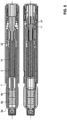
- FIGS 1 to 6 show a first embodiment of an administration device according to the present invention with a blocking device for blocking an actuating element.
- Figures 7a and 7b show a second embodiment of a blocking device for blocking an actuating element.
- Figures 1 to 5 are each shown in two views, with the second, lower view rotated by 90° compared to the first, upper view.
- the administration device uses a two-chamber carpule as a container for a fluid product.
- the fluid product is dispensed from the carpule by advancing a drive element via a dispensing spring. Therefore, the fluid product is dispensed automatically as soon as the dispensing spring is activated.
- the administration device has a fixed dosage, i.e., the dispensed volume is predetermined. The advance of the drive element is therefore also predetermined and cannot be individually adjusted.
- the administration device is blocked after a single dispensing and is disposed of after dispensing.
- a blocking device according to the present invention can nevertheless be advantageously used in reusable administration devices, in devices with individual dosing or manual dispensing and also in devices with single-chamber cartridges.
- distal and proximal refer to the end of the administration device at which the fluid product is dispensed and the opposite end, respectively.
- the administration device comprises a housing 1, a receiving device for receiving the fluid product in the form of a carpule holder 2, a drive member 3 with a holding device in the form of holding arms 4, a blocking device in the form of a blocking ring 5 and an actuating element in the form of a release button 6.
- a two-chamber carpule 7 is housed in the carpule holder 2.
- the two-chamber carpule has a first plug 8a and a second plug 8b.
- the second plug 8b closes the two-chamber carpule at the proximal end.
- the two-chamber carpule has a taper whose opening is sealed by a membrane.
- the membrane can be pierced by a cannula of an injection needle unit.
- the injection needle unit is not shown in the figures.
- a first chamber 9a is formed, in which a dry or lyophilized active ingredient is housed (not shown).
- a second chamber is formed, in which the solvent for the active ingredient is stored.
- the drive member 3 is sleeve-shaped.
- a drive spring 10 is arranged inside the drive member 3 and is clamped between a distal stop on the sleeve base of the drive member and a proximal stop on a housing-fixed element 11.
- the drive member 3 is held relative to the housing element 11 by snap arms 12, which releasably snap into place behind a stop of the housing element 11.
- the holding arms 4 are mounted at the distal end of the drive member 3 such that, in this initial position, they project laterally from a longitudinal axis of the output member. In the embodiment shown, two holding arms are shown, which are spread apart from one another. Of course, three or more such holding arms 4 can also be provided.
- the blocking ring 5 is in the initial state of the Figure 1 in a blocking position in which it blocks actuation of the release button 6, i.e. the release button 6 cannot be pressed longitudinally into the housing 1.
- the blocking ring 5 has a blocking stop 14 which bears against a counter-stop 15 on the release button 6. Due to the abutment of the blocking stop 14 of the blocking ring 5 and the counter-stop 15 of the release button 6, the release button 6 cannot be actuated, i.e. it cannot be pressed into the housing along its longitudinal axis relative to the housing.
- the blocking ring 5 is fixedly mounted longitudinally relative to the housing, but can be rotated relative to the housing.
- the blocking stop 14 can be implemented, for example, by ribs or cams on the blocking ring or by the proximal edge of the blocking ring 5.
- the blocking ring 15 is sleeve-like and surrounds the snap arms 12 of the drive member 3.
- the inner peripheral surface of the blocking ring 5 rests against the snap arms 12 in such a way that they cannot be released from their snap-in position behind the housing element 11.
- the blocking ring 5 thus blocks, on the one hand, the actuation of the release button 6 and, on the other hand, the release of the snap arms 12.
- the initial state corresponds to the delivery state in which the administration device is delivered to a user. Operation of the administration device is not possible in this state.
- FIG 2 The delivery device is shown in a mixed state, in which the active ingredient of chamber 9a of the dual-chamber carpule 7 is mixed with the solvent of chamber 9b.
- the completion of mixing can be indicated by a tactile, acoustic, or visual signal.
- the plugs 8a and 8b were moved within the carpule 7 until the plug 8a comes to rest on a bypass 16 through which the solvent can flow into the chamber 9a and the plug 8b comes to rest on the plug 8a.
- the carpule holder 2 is screwed into the housing 1 so that the drive member, which in this state is at rest relative to the housing, moves the plugs 8a and 8b relative to the carpule 7.
- an internal thread is provided on the inside of the housing and an external thread on the outside of the carpule holder.
- the holding arms 4 have slipped off the proximal edge of the carpule 7 and have been moved radially inwards in the direction of the longitudinal axis of the drive member.
- the ends of the holding arms 4 have inclined surfaces along which the holding arms 4 are deflected inwards as soon as the proximal edge of the carpule 7 is pressed with sufficient force against the inclined surfaces, as is the case when the carpule holder 2 is screwed into the housing 1.
- the holding arms 4 move inwards towards each other and form a plunger for the plug 8b of the carpule 7.
- the carpule 7 continues to be held in its defined position in the carpule holder 2, while the plugs 8a and 8b are displaced within the carpule 7.
- the retaining arms 4 form a clamping fit with the inner wall of the cartridge 7, as they exhibit a radially outward preload since they were bent radially inward. This clamping fit serves to hold the cartridge in a defined position in the cartridge holder.
- an injection needle unit is attached to the carpule holder 2 at the distal end in such a way that a cannula pierces the membrane of the carpule 2, thus establishing a fluid connection to chamber 9a.
- Slightly further screwing in the carpule holder 7 leads to a further advancement of the plugs 8a and 8b, allowing any air in the chamber 9a to escape. This advancement is normally continued until a small amount of the active ingredient 9a emerges from the cannula of the injection needle unit.
- the completion of the venting process can be indicated by a tactile, acoustic, or visual signal.
- FIG. 3 This vented state is in Figure 3
- the injection needle unit has been omitted for the sake of simplicity.
- the blocking ring 5 is moved from the blocking position to a release position.
- the cartridge holder has a stop 17 and the blocking ring has a counter-stop 18.
- the stop 17 of the cartridge holder 2 is designed such that it abuts against the counter-stop 18 of the blocking ring 5 during the rotating movement of the cartridge holder in the circumferential direction.
- the cartridge holder takes the blocking ring 5 with it, so that it is rotated relative to the housing 1 and the release button 6.
- the blocking stop is activated when turning 14 of the blocking ring 5 is turned away from the counter-stop 15 of the release button 6 until a groove or channel 19 of the blocking ring is opposite the counter-stop 15, within which the counter-stop 15 of the release button 6 can be moved in the longitudinal direction.
- the inner surfaces of the blocking ring 5, which prevent the snap arms 12 from snapping out of their snap position, are also rotated away from this position.
- recesses in the sleeve surface of the blocking ring 5 are opposite the snap arms 12. The blocking ring 5 is therefore also in a release position relative to the snap arms 12.
- FIG. 4 The administration device is shown in a triggered state, in which the trigger button 6 has been pressed into the housing 1 along its longitudinal axis relative to the housing 1. In doing so, the counter-stops 15 of the trigger button 6 have been displaced within the grooves 19 of the blocking ring 5.
- the trigger button 6 has inwardly projecting webs 20 which, in the triggered or inserted state of the trigger button, bear against inclined surfaces at the proximal end of the snap arms 12 and, when the trigger button 6 is advanced, spread these radially outward so that the ends of the snap arms come to rest within the recesses in the blocking ring 5.
- the snap arms 12 By spreading the snap arms 12, the securing of the drive member 3 on the housing element 11 is released.
- the spring force of the drive spring 10 begins to act and presses against the drive member 3.
- the drive member 3 is advanced relative to the carpule 7 by the force of the spring 10 and drives the plugs 8a and 8b within the carpule 7, so that the active ingredient is released from the chamber 9a.
- the drive spring 10 advances the drive member 3 into the carpule until a projection 21 provided on the drive member 3 strikes an edge of the housing element 11. As soon as the projection 21 strikes the housing element 11, the release of the active ingredient is terminated.
- a flexible arm 22 is provided on the drive member 3. Upon completion of the dispensing, the flexible arm 22 extends into a recess in the carpule holder and serves as a block for movement of the drive member 3 in the proximal direction. Furthermore, when the arm 22 engages the recess in the carpule holder, it generates an acoustic noise, indicating that the dispensing has ended.
- FIGs 7a and 7b A second embodiment of an administration device with a blocking device according to the invention is shown.
- the blocking device is arranged on the actuating element in the form of the release button.
- a locking arm 23 protrudes from the trigger button 6 in the longitudinal direction of the administration device.
- the locking arm 23 and the trigger button 6 are formed as a single piece.
- a blocking stop 24 is provided on the locking arm 23, which abuts a longitudinal stop of the housing element 11 in the longitudinal direction. By blocking the blocking stop 24 against the longitudinal stop 25, the trigger button 6 cannot be pressed longitudinally into the housing 1.
- the carpule holder 2 has a locking device with which it locks relative to the housing as soon as the blocking device is in a release position, so that a turning back of the carpule holder and thus a renewed blocking of the release button is prevented.
Landscapes
- Health & Medical Sciences (AREA)
- Vascular Medicine (AREA)
- Engineering & Computer Science (AREA)
- Anesthesiology (AREA)
- Biomedical Technology (AREA)
- Heart & Thoracic Surgery (AREA)
- Hematology (AREA)
- Life Sciences & Earth Sciences (AREA)
- Animal Behavior & Ethology (AREA)
- General Health & Medical Sciences (AREA)
- Public Health (AREA)
- Veterinary Medicine (AREA)
- Infusion, Injection, And Reservoir Apparatuses (AREA)
Description
- Die vorliegende Erfindung betrifft eine Vorrichtung zur Verabreichung eines fluiden Produkts, wie z. B. fluide Medikamente, Pharmazeutika oder Kosmetika. Insbesondere betrifft die Erfindung eine Vorrichtung zur Verabreichung eines fluiden Produkts, welches in einer Zweikammerkarpule vor der Anwendung abzumischen ist.
- Bei der Behandlung verschiedener Erkrankungen, wie z.B. Diabetes und bei Wachstumsstörungen, werden Injektionsgeräte, so genannte Pens, verwendet, um das Medikament in Form eines fluiden Produkts in das Körpergewebe zu injizieren. Derartige Pens können auch zu pharmazeutischen oder kosmetischen Zwecken verwendet werden. Ein Pen besteht im Wesentlichen aus einer Verabreichungseinrichtung, welche in einem Pengehäuse untergebracht ist, und einer Aufnahmevorrichtung zur Aufnahme des fluiden Produkts, wie z.B. einem Karpulenhalter, der eine Karpule in sich aufnimmt und mit dem Pengehäuse verbunden wird, um die Karpule an die Verabreichungseinrichtung anzuschliessen. Die Verabreichungseinrichtung besteht in der Regel aus einer Mechanik, welche einen Stopfen in der Karpule antreiben kann. An dem der Mechanik gegenüberliegenden Ende des Karpulenhalters wird im Allgemeinen eine Injektionsnadeleinheit angebracht, welche eine Fluidverbindung zu dem fluiden Produkt in der Karpule bildet. Der Injektionspen umfasst einen Auslöseknopf, durch dessen Betätigung die Verabreichungsmechanik aktiviert wird, so dass durch die Injektionsnadel das Medikament aus der Karpule injiziert werden kann. Aus dem Stand der Technik ist bekannt, den Auslöseknopf zu blockieren, abzudecken oder anderweitig gegen ein ungewolltes Auslösen zu Sichern. Die Blockierung oder Sicherung wird kurz vor der Anwendung des Injektionspens gelöst, um die Injektion vornehmen zu können.
- In der Praxis finden oftmals Zweikammer-Karpulen Anwendung, die z.B. für den Einsatz von Hormonpräparaten vorgesehen sind. Die Zweikammer-Karpulen weisen eine erste Kammer mit einem lyophilisierten Wirkstoff und eine zweite Kammer mit einem Lösungsmittel auf. Der Wirkstoff wird erst kurz vor der Verabreichung in dem Lösungsmittel gelöst, in dem das Lösungsmittel in die erste Kammer mit dem Wirkstoff geleitet wird. Diese Zweikammer-Karpulen weisen zwei Stopfen auf welche die beiden Kammern von einander trennen. Beim Abmischen des Wirkstoffes werden die beiden Stopfen innerhalb der Karpule derart verschoben, dass das Lösungsmittel über einen Bypass in die Wirkstoffkammer gelangen kann. Vor allem bei der Verwendung derartiger Zweikammer-Karpulenn in einem Injektionspen ist es wichtig, das keine ungewünschte oder vorzeitige Verabreichung eingeleitet wird, da in einem solchen Fall noch keine vollständige Abmischung des Medikaments vorliegen kann.
- Aus der
WO2007/002052A2 ist ein Autoinjektor mit einem Anzeigesystem bekannt, wobei der gebrauchsbereite Zustand des Autoinjektors anzeigbar ist. Dabei ist ein Auslöseknopf des Autoinjektors aus dem Gehäuse des Autoinjektors bewegbar. - Ferner ist aus der
US 6,893,420B2 ist eine Zweikammer-Injektionsvorrichtung bekannt, wobei die Injektion erst nach dem Abmischvorgang auslösbar ist. - Es ist eine Aufgabe der vorliegenden Erfindung, eine Vorrichtung zur Verabreichung eines fluiden Produktes zu schaffen, bei dem ein unbeabsichtigtes oder vorzeitiges Betätigen der Vorrichtung verhindert wird und somit die Sicherheit der Vorrichtung erhöht wird.
- Diese Aufgabe wird durch eine Vorrichtung zur Verabreichung eines fluiden Produkts gemäss den Patentansprüchen 1, 6 und 10 erfüllt. Bevorzugte Ausführungsformen einer solchen Vorrichtung gehen aus den Unteransprüchen hervor.
- Demnach umfasst die Vorrichtung zur Verabreichung eines fluiden Produkts ein Gehäuse zur Aufnahme einer Verabreichungseinrichtung, ein Betätigungselement zum Betätigen der Verabreichungseinrichtung, eine Aufnahmevorrichtung zur Aufnahme des fluiden Produkts und eine Blockiereinrichtung zum Blockieren des Betätigungselements. Das Gehäuse der Vorrichtung kann hülsenartig ausgebildet sein, so dass die Vorrichtung die Gestalt eines Pens, bzw. Stiftes annimmt. Wesentlich bei der Gestaltung des Gehäuses ist, dass die Verabreichungseinrichtung darin ohne Beeinträchtigung ihrer Funktion untergebracht werden kann. Es ist auch möglich, dass das Gehäuse Funktionselemente der Verabreichungseinrichtung aufweist und somit einen Teil der Verabreichungseinrichtung bildet. Die Verabreichungseinrichtung besteht z.B. aus einer Mechanik, die in der Regel ein Vorschubglied, wie etwa eine Kolbenstange aufweist, welches gegenüber dem Gehäuse in Richtung der Aufnahmevorrichtung für das fluide Produkt vorgeschoben werden kann. Dort trifft es im Allgemeinen auf einen Stopfen der Aufnahmevorrichtung, so dass durch das Verschieben des Vorschubgliedes auch der Stopfen in der Aufnahmevorrichtung angetrieben und das fluide Produkt ausgeschüttet wird. Der Antrieb des Vorschubgliedes kann manuell erfolgen. Es ist jedoch auch möglich, einen Antrieb in Form einer vorgespannten Feder vorzusehen. Weiter sind zudem auch nicht mechanische Antriebe, wie z.B. Gasantriebe bekannt.
- Das Betätigungselement zum Betätigen der Verabreichungseinrichtung ist gegenüber dem Gehäuse beweglich, um auf die Verabreichungseinrichtung wirken zu können. Das Betätigungselement kann in Form eines Knopfes aus dem Gehäuse herausragen. Es ist jedoch auch möglich, das Betätigungselement seitlich am Gehäuse anzubringen, z.B. in Form eines Schiebers. Mit dem Betätigungselement kann zum Betätigen der Verabreichungsmechanik, z.B. das Vorschubglied unmittelbar angetrieben werden, oder es kann ein vorgespanntes Federelement aus der Vorspannung gelöst werden, welches wiederum auf das Vorschubglied wirkt.
- In der Aufnahmevorrichtung zur Aufnahme des fluiden Produkts ist das fluide Produkt untergebracht. Vorzugsweise befindet sich das fluide Produkt in einer Karpule, welche in die Aufnahmevorrichtung eingesetzt werden kann. Derartige Karpulen weisen in der Regel ein erstes Ende auf, welches durch einen Stopfen abgeschlossen ist und ein zweites Ende, das durch eine dünne Membran abgeschlossen ist, durch welche bei der Anwendung eine Kanüle einer Injektionsnadeleinheit durchgestochen werden kann. Die Aufnahmevorrichtung mit der Karpule kann an die Verabreichungsmechanik angeschlossen werden, in dem die Aufnahmevorrichtung in das Gehäuse eingesetzt oder an das dem Gehäuse angebracht wird.
- Zum Blockieren des Betätigungselements weist die Vorrichtung zur Verabreichung eines fluiden Produkts eine Blockiereinrichtung auf. Die Blockiereinrichtung verhindert die Betätigung des Betätigungselements und somit die Betätigung der Verabreichungseinrichtung, wenn sich die Blockiereinrichtung in einer Blockierposition befindet. Die Blockiereinrichtung kann von der Blockierposition in eine Freigabeposition bewegt werden, in der das Betätigungselement zur Verabreichung des fluiden Produkts mittels der Verabreichungseinrichtung betätigt werden kann.
- Gemäss der vorliegenden Erfindung ist die Aufnahmevorrichtung relativ zum Gehäuse drehbar gelagert, wobei durch Drehung der Aufnahmevorrichtung relativ zum Gehäuse die Blockiereinrichtung von der Blockierposition in die Freigabeposition bewegbar ist. Dabei wird die Aufnahmevorrichtung beispielsweise um eine Längsachse des Gehäuses, bzw. der Aufnahmevorrichtung, gedreht. Somit kann mittels der Drehung der Aufnahmevorrichtung der Pen entsichert und die Verabreichungseinrichtung mit dem Betätigungselement ausgelöst werden.
- Eine derartige Entriegelung der Blockiereinrichtung ist insbesondere bei der Verwendung von Zweikammer-Karpulen vorteilhaft, welche für den Abmischvorgang in das Gehäuse der Verabreichungsvorrichtung eingedreht bzw. eingeschraubt werden. In diesem Fall kann mittels dem einen Drehvorgang z.B. zum einen das Abmischen in der Zweikammer-Karpule ausgelöst werden und zum anderen die Blockiereinrichtung der Verabreichungsvorrichtung in eine Freigabeposition bewegt werden. Möglich ist es auch, dass die Aufnahmevorrichtung mittels einem Bajonettverschluss an dem Gehäuse angeordnet wird, wobei auch der Bajonettverschluss durch eine Drehbewegung erzeugt wird. Auch bei dieser Drehung kann gemäss der vorliegenden Erfindung gleichzeitig die Blockiereinrichtung in eine Freigabeposition bewegt werden.
- Um die Blockiereinrichtung von der Blockierposition in die Freigabeposition zu bewegen, weist vorzugsweise die Aufnahmevorrichtung einen Anschlag und die Blockiereinrichtung einen Gegenanschlag auf. Der Anschlag der Aufnahmevorrichtung und der Gegenanschlag der Blockiereinrichtung wirken derart zusammen, dass sie beim Drehen der Aufnahmevorrichtung gegenüber dem Gehäuse an einander anschlagen und bei einem weiteren Verdrehen der Aufnahmevorrichtung die Blockiereinrichtung mitnehmen und aus der Blockierposition in die Freigabeposition bewegen. Hierfür ist die Blockiereinrichtung z.B. relativ zum Gehäuse in Umfangsrichtung des Gehäuses verdrehbar.
- Sobald sich die Blockiereinrichtung in der Freigabeposition befindet kann das Betätigungselement betätigt werden. Vorzugsweise wird das Betätigungselement in der Freigabeposition der Blockiereinrichtung entlang der Gehäuselängsachse relativ zum Gehäuse bewegt. Beispielsweise wird ein an einem Ende aus dem Gehäuse ragender Betätigungsknopf in das Gehäuse eingedrückt bzw. eingeschoben.
- Gemäss einer ersten Ausführungsform der vorliegenden Erfindung ist die Blockiereinrichtung am Betätigungselement angeordnet. Beispielsweise können die Blockiereinrichtung und das Betätigungselement einstückig ausgebildet sein. In diesem Fall können die Blockiereinrichtung und das Betätigungselement aus einem Stück gefertigt werden. Es ist jedoch auch möglich, die Blockiereinrichtung nachträglich an dem Betätigungselement fest anzubringen. In einer Variante bewegt sich dann das Betätigungselement mit der Blockiereinrichtung mit, wenn die Blockiereinrichtung von der Blockierposition in die Freigabeposition bewegt wird. Beispielsweise wird das Betätigungselement beim Drehen der Aufnahmevorrichtung mitgedreht.
- In einer anderen Variante ist die Blockiereinrichtung vorzugsweise als ein flexibler Arm ausgebildet. Der flexible Arm ist in Umfangsrichtung einer Achse des Betätigungselements auslenkbar, das heisst er kann sich in Drehrichtung um die Längsachse aus seiner Ruhelage heraus verbiegen. In dieser Ausführungsform bildet der flexible Arm den Gegenanschlag der Blockiereinrichtung, der mit dem Anschlag der Aufnahmeeinrichtung zusammenwirkt. Beim Verdrehen der Aufnahmevorrichtung schlägt deren Anschlag an dem flexiblen Arm an und lenkt den Arm aus der Ruhelage aus, wodurch die Blockiereinrichtung in eine Freigabeposition bewegt wird.
- Das Blockieren des Betätigungselements wird vorzugsweise durch einen Blockieranschlag an der Blockiereinrichtung ausgeführt, der in der Blockierposition an einem Längsanschlag am Gehäuse, bzw. an einem in Längsrichtung gehäusefesten Teil, anschlägt. Als Längsanschlag soll ein Anschlag verstanden werden, der eine Bewegung entlang einer Längsachse der Verabreichungsvorrichtung blockiert. Liegt der Blockieranschlag an dem Längsanschlag an, kann das Betätigungselement nicht in dieser Längsrichtung betätigt werden. Ein Eindrücken oder Einschieben des Betätigungselements in das Gehäuse ist somit blockiert. Diese Blockierung wird durch das Auslenken des flexiblen Armes aufgehoben, indem der Blockieranschlag an der Blockiereinrichtung durch die Auslenkung des flexiblen Arms beim Drehen der Aufnahmeeinrichtung von dem Längsanschlag seitlich wegbewegt wird. In der ausgelegten Stellung des flexiblen Armes befindet sich die Blockiereinrichtung in einer Freigabeposition. Der Blockieranschlag kann dann seitlich in Längsrichtung an dem Längsanschlag vorbei geführt werden, wenn das Betätigungselement in das Gehäuse hineinbewegt wird.
- In einer zweiten Ausführungsform der Erfindung ist die Blockiereinrichtung als Drehelement ausgebildet, welches relativ zum Betätigungselement gedreht werden kann. In diesem Fall weist die Blockiereinrichtung einen Blockieranschlag auf, der in der Blockierposition an einem Längsanschlag am Betätigungselement oder am Gehäuse, bzw. an einem gehäusefesten Teil, anschlägt. Das Betätigungselement ist auch in dieser Ausführung somit gegenüber der Blockiereinrichtung in der Blockierposition nicht in Längsrichtung des Gehäuses verschiebbar. Ist der Längsanschlag am Betätigungselement vorgesehen, wird das Drehelement derart drehbar im Gehäuse gelagert, dass es relativ zum Gehäuse nicht in Längsrichtung verschiebbar ist. Durch Verdrehen des Drehelements mittel der Drehung der Aufnahmevorrichtung wird der Blockieranschlag vom Längsanschlag am Betätigungselement entfernt und die Blockierung aufgehoben. Das Betätigungselement kann dann relativ zum Gehäuse und zum Drehelement in Längsrichtung verschoben werden.
- Ist der Längsanschlag am Gehäuse oder einem gehäusefesten Teil vorgesehen, wird das Drehelement derart im Gehäuse gelagert, dass es in der Blockierposition relativ zum Gehäuse drehbar, aber nicht längsverschiebbar ist und in der Freigabeposition relativ zum Gehäuse in Längsrichtung verschoben werden kann. Die Blockierung wirkt demnach zwischen Blockiereinrichtung in Form des Drehelements und dem Gehäuse. Wird das Drehelement durch die Drehung der Aufnahmevorrichtung relativ zum Gehäuse verdreht, wird der Blockieranschlag vom Längsanschlag am Gehäuse oder dem gehäusefesten Teil wegbewegt. Die Blockiereinrichtung kann dann gemeinsam mit dem Betätigungselement relativ zum Gehäuse in Längsrichtung verschoben werden. Somit ist letztlich auch bei diesen Varianten das Betätigungselement an einer Betätigung gehindert. Die Blockiereinrichtung, bzw. das Drehelement, werden durch die Drehbewegung der Aufnahmevorrichtung relativ zum Gehäuse mittels dem Anschlag an der Aufnahmevorrichtung und dem Gegenanschlag an der Blockiereinrichtung verdreht. Durch diese Verdrehung wird der Anschlag zwischen dem Blockieranschlag der Blockiereinrichtung und dem Längsanschlag am Betätigungselement oder am Gehäuse, bzw. am gehäusefesten Teil, aufgehoben und diese Anschläge können in Längsrichtung an einander vorbei bewegt werden. Demnach befindet sich in dieser Position die Blockiereinrichtung in einer Freigabeposition in der das Betätigungselement betätigt werden kann.
- Es ist vorteilhaft, wenn das Drehelement der Blockiereinrichtung in der Blockierposition gesichert ist. Eine derartige Sicherung kann z.B. durch einen Klemmsitz oder durch eine Vorspannung eines Federelements erfolgen. Beim Drehen der Aufnahmevorrichtung wird dann das Drehelement aus dem Klemmsitz geschoben, bzw. entgegen der Federspannung ausgelenkt.
- Bei beiden Ausführungsformen der vorliegenden Erfindung ist eine Rasteinrichtung vorgesehen, welche die Aufnahmevorrichtung in der Freigabeposition der Blockiereinrichtung relativ zum Gehäuse verrastet. Durch die Verrastung wird sichergestellt, dass die Aufnahmevorrichtung nicht in der Gegenrichtung zurückdreht und somit die Blockiereinrichtung aus der Freigabeposition wieder zurück in eine Blockierposition bewegt wird. Eine solche Rasteinrichtung kann beispielsweise durch einen Schnapper an der Aufnahmevorrichtung realisiert werden, der in eine Vertiefung beispielsweise am Gehäuse einschnappt.
- Besonders vorteilhaft ist die Anwendung der vorliegenden Erfindung beim Einsatz einer Zweikammer-Karpule in einer Vorrichtung zur Verabreichung eines fluiden Produktes. Die Aufnahmevorrichtung für die Zweikammer-Karpule weist ein Gewinde und das Gehäuse ein Gegengewinde auf Somit kann die Aufnahmevorrichtung in das Gehäuse eingedreht bzw. eingeschraubt werden. Beim Einsatz der Zweikammer-Karpule kann das Eindrehen der Aufnahmevorrichtung in das Gehäuse zum Abmischen der Komponenten in der Zweikammer-Karpule verwendet werden. Durch das Eindrehen der Aufnahmevorrichtung in das Gehäuse wird zunächst ein in der Zweikammer-Karpule z.B. mittels dem Vorschubglied der Verabreichungsmechanik vorgeschoben. Der Vorschub wird über das Lösungsmittel in der ersten Kammer auf den zweiten Stopfen übertragen der die Lösungsmittelkammer von der Wirkstoffkammer trennt. Die beiden Stopfen werden so lange gleichmässig verschoben, bis der zweite Stopfen an einem Bypass in der Karpulenwand angekommen ist, durch den das Lösungsmittel aus der Lösungsmittelkammer in die Wirkstoffkammer gelangen kann. Der erste Stopfen wird solange vorgeschoben bis das Lösungsmittel in der ersten Kammer ist und er am zweiten Stopfen zu liegen kommt. Vorzugsweise ist das Eindrehen der Zweikammer-Karpule derart vorgesehen, dass die Blockiereinrichtung von der Blockierposition in die Freigabeposition bewegt ist, sobald das Lösungsmittel vollständig aus der Lösungsmittelkammer in die Wirkstoffkammer gelangt ist. Mittels der Rasteinrichtung wird die Aufnahmevorrichtung in der Freigabeposition der Blockiereinrichtung relativ zum Gehäuse verrastet, so dass die Vorrichtung zur Verabreichung in dieser Stellung fertig für eine Injektion ist, das heisst, der Wirkstoff ist vollständig abgemischt und die Blockierung der Verabreichungsvorrichtung ist aufgehoben. Sobald eine Injektionsnadeleinheit auf die Aufnahmevorrichtung aufgesetzt ist, kann eine Injektion durchgeführt werden. Bei dieser Ausführungsform ist es vorteilhaft, dass kein gesonderter Handgriff zur Entriegelung der Blockiereinrichtung notwendig ist, sondern die Auflösung der Blockierung durch das ohnehin notwendige Abmischen der Zweikammer-Karpule durchgeführt wird.
- Bevorzugte Ausführungsbeispiele der Erfindung werden nachfolgend Anhand der Figuren erläutert. An den Ausführungsbeispielen offenbar werdende Merkmale bilden je einzeln und in jeder Kombination die Gegenstände der Ansprüche und auch die vorstehend beschriebenen Ausgestaltungen in vorteilhafter Weise weiter. Es zeigen:
- Figur 1
- eine Verabreichungsvorrichtung in einem Ausgangszustand,
- Figur 2
- die Verabreichungsvorrichtung in einem abgemischten Zustand,
- Figur 3
- die Verabreichungsvorrichtung in einem entlüfteten Zustand,
- Figur 4
- die Verabreichungsvorrichtung in einem ausgelösten Zustand,
- Figur 5
- die Verabreichungsvorrichtung in einem Zustand nach der Ausschüttung eines Produkts,
- Figur 6a
- Innenansicht der Verabreichungsvorrichtung in einer Blockierposition,
- Figur 6b
- Innenansicht der Verabreichungsvorrichtung in einer Freigabeposition,
- Figur 7a
- Detailansicht einer zweiten Ausführungsform einer Verabreichungsvorrichtung in einer Blockierposition und
- Figur 7b
- Detailansicht der zweiten Ausführungsform der Verabreichungsvorrichtung in einer Freigabeposition.
- Die
Figuren 1 bis 6 zeigen eine erste Ausführungsform einer Verabreichungsvorrichtung gemäss der vorliegenden Erfindung mit einer Blockiereinrichtung zum Blockieren eines Betätigungselements. In den Figuren 7a und 7b ist eine zweite Ausführungsform einer Blockiereinrichtung zum Blockieren eines Betätigungselements dargestellt. DieFiguren 1 bis 5 sind jeweils in zwei Ansichten gezeigt, wobei die zweite, untere Ansicht gegenüber der ersten, oberen Ansicht um 90° gedreht ist. - Das Verabreichungsgerät gemäss der ersten Ausführungsform verwendet eine Zweikammer-Karpule als Behälter für ein fluides Produkt. Die Ausschüttung des fluiden Produkts aus der Karpule erfolgt durch den Vorschub eines Antriebsglieds mittels einer Ausschüttfeder. Es erfolgt daher eine automatische Ausschüttung des fluiden Produkts, sobald die Ausschüttfeder aktiviert wird. Die Verabreichungsvorrichtung weist eine fixe Dosierung auf, das heisst, das Ausschüttvolumen ist fest vorgegeben. Der Vorschub des Antriebsglieds ist daher ebenfalls fest vorgegeben und kann nicht individuell eingestellt werden. Das Verabreichungsgerät ist nach einer einzigen Ausschüttung blockiert und wird nach der Ausschüttung entsorgt.
- Für einen Fachmann ist es klar, dass eine Blockiereinrichtung gemäss der vorliegenden Erfindung gleichwohl bei wieder verwendbaren Verabreichungsgeräten, bei Geräten mit individueller Dosierung oder manueller Ausschüttung und auch bei Geräten mit Einkammer-Karpulen vorteilhaft eingesetzt werden kann.
- Im Folgenden wird mit den Begriffen distal, bzw. proximal, das Ende des Verabreichungsgeräts, an welchem das fluide Produkt ausgeschüttet wird, bzw. das gegenüberliegende Ende, bezeichnet.
- Das Verabreichungsgerät gemäss der ersten Ausführungsform der vorliegenden Erfindung weist ein Gehäuse 1, eine Aufnahmevorrichtung zur Aufnahme des fluiden Produkts in Form eines Karpulenhalters 2, ein Antriebsglied 3 mit einer Halteeinrichtung in Form von Haltearmen 4, eine Blockiereinrichtung in Form eines Blockierrings 5 und ein Betätigungselements in Form eines Auslöseknopfes 6 auf.
- In dem Karpulenhalter 2 ist eine Zweikammer-Karpule 7 untergebracht. Die Zweikammer-Karpule weist einen ersten Stopfen 8a und einen zweiten Stopfen 8b auf. Der zweite Stopfen 8b schliesst die Zweikammer-Karpule am proximalen Ende ab. Am distalen Ende weist die Zweikammer-Karpule eine Verjüngung auf, deren Öffnung durch eine Membran abgeschlossen ist. Die Membran kann durch eine Kanüle einer Injektionsnadeleinheit durchstochen werden. Die Injektionsnadeleinheit wird in den Figuren nicht dargestellt. Zwischen der Membran und dem ersten Stopfen 8a ist eine erste Kammer 9a ausgebildet, in welcher ein trockener bzw. lyophilisierter Wirkstoff untergebracht wird (nicht dargestellt). Zwischen dem ersten Stopfen 8a und dem zweiten Stopfen 8b wird eine zweite Kammer gebildet, in welcher das Lösungsmittel für den Wirkstoff gelagert wird.
- Das Antriebsglied 3 ist hülsenartig ausgebildet. Im inneren des Antriebsglieds 3 ist eine Antriebsfeder 10 angeordnet, die zwischen einem distalen Anschlag am Hülsenboden des Antriebsglieds und einem proximalen Anschlag an einem gehäusefesten Element 11 eingespannt ist. Im Ausgangszustand der
Figur 1 wird das Antriebsglied 3 relativ zum Gehäuseelement 11 durch Schnapparme 12 gehalten, welche hinter einem Anschlag des Gehäuseelements 11 lösbar einschnappen. Am distalen Ende des Antriebsglieds 3 sind die Haltearme 4 derart angebracht, dass sie in dieser Ausgangsposition von einer Längsachse des Abtriebsglieds seitlich abragen. In der gezeigten Ausführungsform sind zwei Haltearme dargestellt, die zueinander aufgespreizt sind. Es können natürlich auch drei oder mehr derartige Haltearme 4 vorgesehen werden. In dem Ausgangszustand inFigur 1 stossen die Haltearme 4 mit ihrem distalen Ende an eine proximale Kante der Karpule 7. Die Haltearme 4 drücken die Karpule 7 gegen eine Schulter 13 des Karpulenhalters 2. Die Karpule 7 wird daher von der Halteeinrichtung in Form der Haltearme 4 in einer definierten Position relativ zum Karpulenhalter 2 gehalten. Eine hin und her Bewegung in proximaler oder distaler Richtung der Karpule im Halter wird dadurch unterbunden. - Der Blockierring 5 befindet sich im Ausgangszustand der
Figur 1 in einer Blockierposition, in der er eine Betätigung des Auslöseknopfes 6 blockiert, d.h. der Auslöseknopf 6 kann nicht in Längsrichtung in das Gehäuse 1 eingedrückt werden. Hierfür weist der Blockierring 5 einen Blockieranschlag 14 auf, der an einem Gegenanschlag 15 am Auslöseknopf 6 ansteht. Aufgrund des Aneinanderstossens des Blockieranschlags 14 des Blockierrings 5 und des Gegenanschlags 15 des Auslöseknopfes 6 kann der Auslöseknopf 6 nicht betätigt werden, das heisst er kann nicht relativ zum Gehäuse entlang der Längsachse in das Gehäuse eingedrückt werden. Hierfür ist der Blockierring 5 relativ zum Gehäuse in Längsrichtung festgelagert, kann jedoch relativ zum Gehäuse verdreht werden. Der Blockieranschlag 14 kann z.B. durch Rippen oder Nocken am Blockierring oder durch die proximale Kante des Blockierrings 5 realisiert werden. - Der Blockierring 15 ist hülsenartig ausgebildet und umgibt die Schnapparme 12 des Antriebsglieds 3. Im Ausgangszustand der
Figur 1 liegt die Innenumfangsfläche des Blockierrings 5 derart aussen an den Schnapparmen 12 an, dass diese nicht aus ihrer Verschnappung hinter dem Gehäuseelement 11 freigegeben werden können. Der Blockierring 5 blockiert somit zum einen eine Betätigung des Auslöseknopfes 6 und zum anderen eine Freigabe der Schnapparme 12. Der Ausgangszustand entspricht einem Auslieferungszustand, wie das Verabreichungsgerät an einen Anwender abgegeben wird. Eine Betätigung des Verabreichungsgeräts ist in diesem Zustand nicht möglich. - In
Figur 2 ist das Verabreichungsgerät in einem abgemischten Zustand gezeigt, in dem der Wirkstoff der Kammer 9a der Zweikammer-Karpule 7 mit dem Lösungsmittel der Kammer 9b abgemischt ist. Die Beendigung des Abmischens kann durch ein taktiles, akustisches oder visuelles Signal angezeigt werden. Wie inFigur 2 gezeigt ist wurden zum Abmischen die Stopfen 8a und 8b innerhalb der Karpule 7 verschoben, bis der Stopfen 8a an einem Bypass 16 zu liegen kommt, durch den das Lösungsmittel in die Kammer 9a fliessen kann und der Stopfen 8b an dem Stopfen 8a zu liegen kommt. Zum Vorschub der Stopfen wird der Karpulenhalter 2 in das Gehäuse 1 eingeschraubt, so dass das Antriebsglied, dass in diesem Zustand relativ zum Gehäuse in Ruhe ist, die Stopfen 8a und 8b relativ zur Karpule 7 verschiebt. Zum Einschrauben des Karpulenhalters ist an der Innenseite des Gehäuses ein Innengewinde und an der Aussenseite des Karpulenhalters ein Aussengewinde vorgesehen. - Wie in
Figur 2 zu sehen ist, sind die Haltearme 4 an der proximalen Kante der Karpule 7 abgerutscht und wurden radial nach innen in Richtung der Längsachse des Antriebsglieds bewegt. Hierfür weisen die Enden der Haltearme 4 schräge Flächen auf, entlang welcher die Haltearme 4 nach innen abgelenkt werden, sobald die proximale Kante der Karpule 7 mit ausreichender Kraft gegen die schrägen Flächen gedrückt wird, wie es beim Einschrauben des Karpulenhalters 2 in das Gehäuse 1 der Fall ist. Die Haltearme 4 bewegen sich dabei nach innen aufeinander zu und bilden einen Stössel für den Stopfen 8b der Karpule 7. Durch den Anschlag der Haltearme 4 an dem Stopfen 8b wird die Karpule 7 weiterhin in ihrer definierten Position in dem Karpulenhalter 2 gehalten, während die Stopfen 8a und 8b innerhalb der Karpule 7 verschoben werden. Unabhängig davon bilden die Haltearme 4 mit der Innenwand der Karpule 7 eine Klemmpassung, bzw. einen Klemmsitz, da sie eine Vorspannung in radialer Richtung nach aussen aufweisen, seitdem sie radial nach innen verbogen wurden. Diese Klemmpassung dient dem Halten der Karpule in einer definierten Position in dem Karpulenhalter. - Nach dem Abmischen der Zweikammer-Karpule kann es notwendig sein, die Kammer 9a mit dem gelösten Wirkstoff zu entlüften, bevor der Wirkstoff injiziert werden kann. Hierfür wird eine Injektionsnadeleinheit auf den Karpulenhalter 2 am distalen Ende derart aufgebracht, dass eine Kanüle die Membran der Karpule 2 durchsticht und somit eine Flüssigkeitsverbindung zur Kammer 9a herstellt. Geringfügiges weiteres Eindrehen des Karpulenhalters 7 führt zu einem weitem Vorschub der Stopfen 8a und 8b, so dass in der Kammer 9a befindliche Luft entweichen kann. Ein Vorschub wird normalerweise so lange durchgeführt, bis eine geringe Menge des Wirkstoffes 9a aus der Kanüle der Injektionsnadeleinheit austritt. Der Abschluss der Entlüftung kann durch ein taktiles, akustisches oder visuelles Signal angezeigt werden.
- Dieser entlüftete Zustand ist in
Figur 3 dargestellt. Auf die Darstellung der Injektionsnadeleinheit wurde aus Gründen der Einfachheit verzichtet. Bei der letzten Einschraubbewegung des Karpulenhalters 2 in das Gehäuse 1, bei dem auch die Karpule entlüftet werden kann, wird der Blockierring 5 von der Blockierposition in eine Freigabeposition bewegt. Wie in denFiguren 6a bis 6d gezeigt ist, weist hierfür der Karpulenhalter einen Anschlag 17 und der Blockierring einen Gegenanschlag 18 auf. Der Anschlag 17 des Karpulenhalters 2 ist derart ausgebildet, dass er bei der Drehbewegung des Karpulenhalters in Umfangsrichtung gegen den Gegenanschlag 18 des Blockierrings 5 anstösst. Bei einem weiteren Verdrehen des Karpulenhalters 2 nimmt der Karpulenhalter den Blockierrings 5 mit, so dass dieser relativ zum Gehäuse 1 und zum Auslöseknopf 6 gedreht wird. Durch diese Drehbewegung wird der Blockierring von der Blockierposition in die Freigabeposition bewegt. Wie inFigur 3 dargestellt ist, wird bei der Drehung der Blockieranschlag 14 des Blockierrings 5 von dem Gegenanschlag 15 des Auslöseknopfes 6 weggedreht, bis dem Gegenanschlag 15 eine Nut oder Rille 19 des Blockierrings gegenüberliegt, innerhalb der der Gegenanschlag 15 des Auslöseknopfes 6 in Längsrichtung verschoben werden kann. - Beim Drehen des Blockierrings 5 mittels dem Karpulenhalter 2 werden zudem die Innenflächen des Blockierrings 5, welche die Schnapparme 12 an einem Ausschnappen aus ihrer Schnappposition hindern, aus dieser Position weggedreht. In der Freigabeposition des Blockierrings 5 liegen den Schnapparmen 12 Aussparungen in der Hülsenfläche des Blockierrings 5 gegenüber. Auch gegenüber den Schnapparmen 12 befindet sich der Blockierring 5 demnach in einer Freigabeposition.
- In
Figur 4 ist die Verabreichungsvorrichtung in einem ausgelösten Zustand dargestellt, in dem der Auslöseknopf 6 relativ zum Gehäuse 1 entlang der Längsachse in das Gehäuse 1 eingedrückt wurde. Dabei wurden die Gegenanschläge 15 des Auslöseknopfes 6 innerhalb der Rillen 19 des Blockierrings 5 verschoben. Der Auslöseknopf 6 weist nach innen ragende Stege 20 auf, die in dem ausgelösten, bzw. eingeschobenen Zustand des Auslöseknopfes gegen schräge Flächen am proximalen Ende der Schnapparme 12 anliegen und diese beim Vorschub des Auslöseknopfes 6 radial nach aussen aufspreizen, so dass die Enden der Schnapparme innerhalb der Aussparungen im Blockierring 5 zu liegen kommen. Durch das Aufspreizen der Schnapparme 12 wird die Sicherung des Antriebsglieds 3 am Gehäuseelement 11 gelöst. In dem ausgelösten Zustand beginnt die Federkraft der Antriebsfeder 10 zu wirken und drückt gegen das Antriebsglied 3. - Wie in
Figur 5 gezeigt ist, wird das Antriebsglied 3 durch die Kraft der Feder 10 relativ zur Karpule 7 vorgeschoben und treibt die Stopfen 8a und 8b innerhalb der Karpule 7 an, so dass der Wirkstoff aus der Kammer 9a ausgeschüttet wird. Die Antriebsfeder 10 schiebt das Antriebsglied 3 so lange in die Karpule vor, bis ein Vorsprung 21, der am Antriebsglied 3 vorgesehen ist, an einer Kante des Gehäuseelements 11 anschlägt. Sobald der Vorsprung 21 am Gehäuseelement 11 anschlägt, ist die Ausschüttung des Wirkstoffes beendet. - In dem dargestellten Ausführungsbeispiel ist an dem Antriebsglied 3 ein flexibler Arm 22 vorgesehen, der bei Beendigung der Ausschüttung in eine Aussparung im Karpulenhalter hineinragt und als Blockierung für eine Bewegung des Antriebsglieds 3 in proximaler Richtung dient. Ferner erzeugt der Arm 22 beim Einrasten in die Aussparung des Karpulenhalters ein akustisches Geräusch, durch welches angezeigt wird, dass die Ausschüttung beendet ist.
- In den
Figuren 7a und 7b ist eine zweite Ausführungsform einer Verabreichungsvorrichtung mit einer erfindungsgemässen Blockiereinrichtung gezeigt. In dieser Variante ist die Blockiereinrichtung am Betätigungselement in Form des Auslöseknopfes angeordnet. Wie inFigur 7a gezeigt ist, ragt von dem Auslöseknopf 6 in Längsrichtung der Verabreichungsvorrichtung ein Verriegelungsarm 23 ab. Der Verriegelungsarm 23 und der Auslöseknopf 6 sind einstückig ausgebildet. An dem Verriegelungsarm 23 ist ein Blockieranschlag 24 vorgesehen, der an einem Längsanschlag des Gehäuseelements 11 in Längsrichtung anschlägt. Durch die Blockierung des Blockieranschlags 24 am Längsanschlag 25 kann der Auslöseknopf 6 nicht in Längsrichtung in das Gehäuse 1 eingedrückt werden. - In
Figur 7a ist der Karpulenhalter 2 bereits in das Gehäuse 1 eingeschraubt. Der Karpulenhalter 2 wird so lange in das Gehäuse eingeschraubt, bis ein Anschlag 17' des Karpulenhalters in Umfangsrichtung gegen einen Gegenanschlag 18' des Verriegelungsarms 23 des Auslöseknopfes 6 stösst. Beim Weiterdrehen des Karpulenhalters 2 wird der Verriegelungsarm 23 in Umfangsrichtung gegenüber seiner Ruhelage ausgelenkt, da der Anschlag 17' gegen den Gegenanschlag 18' wirkt. Dadurch wird der Blockieranschlag des Auslöseknopfes 6 aus seiner Blockierposition gegenüber dem Längsanschlag 25 des Gehäuseelements 11 ausgelenkt und kommt gegenüber einer Aussparung im Gehäuseelement 11 zu liegen. Die Blockiereinrichtung zum Blockieren des Auslöseknopfes 6 befindet sich nun in einer Freigabeposition, in der der Auslöseknopf 6 entlang der Längsachse in das Gehäuse 1 eingedrückt werden kann. Dabei wird der Blockieranschlag 24 durch die Aussparung im Gehäuseelement 11 geführt. - Bei dieser Ausführungsform weist der Karpulenhalter 2 eine Rasteinrichtung auf, mit der er gegenüber dem Gehäuse verrastet, sobald die Blockiereinrichtung in einer Freigabeposition ist, damit ein Zurückdrehen des Karpulenhalters und somit eine erneute Blockierung des Auslöseknopfes verhindert wird.
-
- 1
- Gehäuse
- 2
- Karpulenhalter
- 3, 3'
- Antriebsglied
- 4, 4'
- Haltearm
- 5
- Blockierring
- 6
- Auslöseknopf
- 7
- Zweikammer-Karpule
- 8a, b
- Stopfen
- 9a, b
- Kammer
- 10
- Antriebsfeder
- 11
- gehäusefestes Element
- 12
- Schnapparme
- 13
- Schulter
- 14
- Blockieranschlag
- 15
- Gegenanschlag
- 16
- Bypass
- 17, 17'
- Anschlag
- 18, 18'
- Gegenanschlag
- 19
- Rille
- 20
- Steg
- 21
- Vorsprung
- 22
- Arm
- 23
- Verriegelungsarm
- 24
- Blockieranschlag
- 25
- Längsanschlag
- 26
- Stössel
Claims (11)
- Vorrichtung zur Verabreichung eines fluiden Produkts umfassend:- ein Gehäuse (1) zur Aufnahme einer Verabreichungseinrichtung,- ein Betätigungselement (6) zum Betätigen der Verabreichungseinrichtung,- eine Aufnahmevorrichtung (2) zur Aufnahme des fluiden Produkts,- eine Blockiereinrichtung (5, 23) zum Blockieren des Betätigungselements (6), wobei- die Aufnahmevorrichtung (2) relativ zum Gehäuse (1) drehbar gelagert ist,- wobei durch Drehung der Aufnahmevorrichtung (2) relativ zum Gehäuse (1) die Blockiereinrichtung (5, 23) von einer Blockierposition in eine Freigabeposition bewegbar ist,wobei eine Rasteinrichtung vorgesehen ist, welche die Aufnahmevorrichtung in der Freigabeposition der Blockiereinrichtung relativ zum Gehäuse verrastet, sodass die Aufnahmevorrichtung nur in eine Drehrichtung drehbar ist, um die Blockiereinrichtung (5, 23) von der Blockierposition in die Freigabeposition zu bewegen, und in der Freigabeposition nicht in die Gegenrichtung zurückgedreht werden kann,dadurch gekennzeichnet, dassdie Aufnahmevorrichtung (7) einen Anschlag (17, 17') und die Blockiereinrichtung (5, 23) einen Gegenanschlag (18, 18') aufweist, die zur Bewegung der Blockiereinrichtung (5, 23) aus der Blockierposition in die Freigabeposition zusammenwirken.
- Vorrichtung zur Verabreichung eines fluiden Produkts nach Anspruch 1, dadurch gekennzeichnet, dass das Betätigungselement (6) in der Freigabeposition der Blockiereinrichtung (5, 23) entlang einer Gehäuselängsachse relativ zum Gehäuse (1) beweglich ist.
- Vorrichtung zur Verabreichung eines fluiden Produkts nach einem der vorhergehenden Ansprüche, dadurch gekennzeichnet, dass die Blockiereinrichtung (23) am Betätigungselement (6) angeordnet ist.
- Vorrichtung zur Verabreichung eines fluiden Produkts nach Anspruch 3, dadurch gekennzeichnet, dass die Blockiereinrichtung (23) und das Betätigungselement (6) einstückig ausgebildet sind.
- Vorrichtung zur Verabreichung eines fluiden Produkts nach einem der Ansprüche 3 oder 4, dadurch gekennzeichnet, dass die Blockiereinrichtung (23) einen Blockieranschlag (24) aufweist, der in der Blockierposition an einem Längsanschlag (25) am Gehäuse (1), bzw. einem in Längsrichtung gehäusefestem Teil (11), anschlägt.
- Vorrichtung zur Verabreichung eines fluiden Produkts umfassend:- ein Gehäuse (1) zur Aufnahme einer Verabreichungseinrichtung,- ein Betätigungselement (6) zum Betätigen der Verabreichungseinrichtung,- eine Aufnahmevorrichtung (2) zur Aufnahme des fluiden Produkts,- eine Blockiereinrichtung (5, 23) zum Blockieren des Betätigungselements (6), wobei die Blockiereinrichtung (23) am Betätigungselement (6) angeordnet ist, wobei- die Aufnahmevorrichtung (2) relativ zum Gehäuse (1) drehbar gelagert ist,- wobei durch Drehung der Aufnahmevorrichtung (2) relativ zum Gehäuse (1) die Blockiereinrichtung (5, 23) von einer Blockierposition in eine Freigabeposition bewegbar ist,wobei eine Rasteinrichtung vorgesehen ist, welche die Aufnahmevorrichtung in der Freigabeposition der Blockiereinrichtung relativ zum Gehäuse verrastet, sodass die Aufnahmevorrichtung nur in eine Drehrichtung drehbar ist, um die Blockiereinrichtung (5, 23) von der Blockierposition in die Freigabeposition zu bewegen, und in der Freigabeposition nicht in die Gegenrichtung zurückgedreht werden kann,dadurch gekennzeichnet, dassdie Blockiereinrichtung einen flexiblen Arm (23) aufweist, der in Umfangsrichtung der Längsachse relativ zum Betätigungselement (6) auslenkbar ist.
- Vorrichtung zur Verabreichung eines fluiden Produkts nach Anspruch 1 oder 2, dadurch gekennzeichnet, dass die Blockiereinrichtung (5) relativ zum Betätigungselement (6) drehbar angeordnet ist.
- Vorrichtung zur Verabreichung eines fluiden Produkts nach dem vorhergehenden Anspruch, dadurch gekennzeichnet, dass die Blockiereinrichtung (5) einen Blockieranschlag (14) aufweist, der in der Blockierposition an einem Längsanschlag (15) am Betätigungselement (6) oder am Gehäuse (1) bzw. einem gehäusefesten Teil (11), anschlägt.
- Vorrichtung zur Verabreichung eines fluiden Produkts nach einem der Ansprüche 7 oder 8, dadurch gekennzeichnet, dass die Blockiereinrichtung (5) ein Verriegelungsmittel umfasst, das in der Blockierposition ein Antriebsglied (3) gegen Vorschub verriegelt.
- Vorrichtung zur Verabreichung eines fluiden Produkts umfassend:- ein Gehäuse (1) zur Aufnahme einer Verabreichungseinrichtung,- ein Betätigungselement (6) zum Betätigen der Verabreichungseinrichtung,- eine Aufnahmevorrichtung (2) zur Aufnahme des fluiden Produkts,- eine Blockiereinrichtung (5, 23) zum Blockieren des Betätigungselements (6), wobei- die Aufnahmevorrichtung (2) relativ zum Gehäuse (1) drehbar gelagert ist,- wobei durch Drehung der Aufnahmevorrichtung (2) relativ zum Gehäuse (1) die Blockiereinrichtung (5, 23) von einer Blockierposition in eine Freigabeposition bewegbar ist,wobei eine Rasteinrichtung vorgesehen ist, welche die Aufnahmevorrichtung in der Freigabeposition der Blockiereinrichtung relativ zum Gehäuse verrastet, sodass die Aufnahmevorrichtung nur in eine Drehrichtung drehbar ist, um die Blockiereinrichtung (5, 23) von der Blockierposition in die Freigabeposition zu bewegen, und in der Freigabeposition nicht in die Gegenrichtung zurückgedreht werden kann,dadurch gekennzeichnet, dassdie Aufnahmevorrichtung (2) eine Zweikammer-Karpule (7) aufnimmt, wobei die Zweikammer-Karpule (7) durch Drehung der Aufnahmevorrichtung (2) abmischbar ist.
- Vorrichtung zur Verabreichung eines fluiden Produkts nach Anspruch 10, dadurch gekennzeichnet, dass die Freigabestellung der Blockiereinrichtung (5, 23) einer Stellung der Zweikammer-Karpule (7) entspricht, in der die Zweikammer-Karpule (7) abgemischt ist.
Applications Claiming Priority (2)
| Application Number | Priority Date | Filing Date | Title |
|---|---|---|---|
| CH1892008 | 2008-02-11 | ||
| PCT/CH2009/000042 WO2009100550A1 (de) | 2008-02-11 | 2009-02-04 | Verabreichungsvorrichtung mit blockierbarem betätigungselement |
Publications (3)
| Publication Number | Publication Date |
|---|---|
| EP2252350A1 EP2252350A1 (de) | 2010-11-24 |
| EP2252350B1 EP2252350B1 (de) | 2016-04-20 |
| EP2252350B2 true EP2252350B2 (de) | 2025-05-28 |
Family
ID=39540794
Family Applications (1)
| Application Number | Title | Priority Date | Filing Date |
|---|---|---|---|
| EP09710102.6A Active EP2252350B2 (de) | 2008-02-11 | 2009-02-04 | Verabreichungsvorrichtung mit blockierbarem betätigungselement |
Country Status (4)
| Country | Link |
|---|---|
| US (1) | US8298175B2 (de) |
| EP (1) | EP2252350B2 (de) |
| CN (1) | CN101998869B (de) |
| WO (1) | WO2009100550A1 (de) |
Families Citing this family (43)
| Publication number | Priority date | Publication date | Assignee | Title |
|---|---|---|---|---|
| WO2003068290A2 (en) | 2002-02-11 | 2003-08-21 | Antares Pharma, Inc. | Intradermal injector |
| WO2006079064A1 (en) | 2005-01-24 | 2006-07-27 | Antares Pharma, Inc. | Prefilled needle assisted jet injector |
| WO2007131013A1 (en) | 2006-05-03 | 2007-11-15 | Antares Pharma, Inc. | Two-stage reconstituting injector |
| US9144648B2 (en) | 2006-05-03 | 2015-09-29 | Antares Pharma, Inc. | Injector with adjustable dosing |
| ES2548447T3 (es) | 2008-03-10 | 2015-10-16 | Antares Pharma, Inc. | Dispositivo de seguridad para inyector |
| WO2009147026A1 (en) * | 2008-06-02 | 2009-12-10 | Shl Group Ab | Medicament delivery device |
| DE102008032372A1 (de) * | 2008-07-09 | 2010-01-21 | Tecpharma Licensing Ag | Zweikammer-Ampullen-Abmischsicherung |
| JP5611208B2 (ja) | 2008-08-05 | 2014-10-22 | アンタレス・ファーマ・インコーポレーテッド | 多数回服用量の注射装置 |
| US8579865B2 (en) | 2009-03-20 | 2013-11-12 | Antares Pharma, Inc. | Hazardous agent injection system |
| DK2611482T3 (en) * | 2010-08-31 | 2018-11-05 | Shl Group Ab | Drug delivery device |
| EP2611481B1 (de) * | 2010-08-31 | 2018-12-12 | SHL Group AB | Vorrichtung zur medikamentenverabreichung |
| KR101521742B1 (ko) * | 2011-02-03 | 2015-05-19 | 에스에이치엘 그룹 에이비 | 약물 주입 장치 |
| US9220660B2 (en) | 2011-07-15 | 2015-12-29 | Antares Pharma, Inc. | Liquid-transfer adapter beveled spike |
| US8496619B2 (en) | 2011-07-15 | 2013-07-30 | Antares Pharma, Inc. | Injection device with cammed ram assembly |
| CH705692A2 (de) | 2011-11-03 | 2013-05-15 | Tecpharma Licensing Ag | Verabreichungsvorrichtung zum Abmischen eines Wirkstoffs mit einer Lösungsflüssigkeit. |
| US8834449B2 (en) | 2012-01-23 | 2014-09-16 | Ikomed Technologies, Inc. | Mixing syringe |
| US9751056B2 (en) | 2012-01-23 | 2017-09-05 | Merit Medical Systems, Inc. | Mixing syringe |
| EP4327849A3 (de) | 2012-03-06 | 2024-04-24 | Antares Pharma, Inc. | Vorgefüllte spritze mit losbrechkraftfunktion |
| KR20150011346A (ko) | 2012-04-06 | 2015-01-30 | 안타레스 팔마, 인코퍼레이티드 | 테스토스테론 조성물의 바늘-보조식 젯 주입 투여 장치 및 방법 |
| WO2013169800A1 (en) | 2012-05-07 | 2013-11-14 | Antares Pharma, Inc. | Injection device with cammed ram assembly |
| DK2953667T3 (da) | 2013-02-11 | 2020-01-27 | Antares Pharma Inc | Nålestøttet jetinjektionsindretning med reduceret udløserkraft |
| EP3572108A1 (de) | 2013-03-11 | 2019-11-27 | Antares Pharma, Inc. | Dosierungsinjektor mit einem zahnradsystem |
| WO2014165136A1 (en) | 2013-03-12 | 2014-10-09 | Antares Pharma, Inc. | Constant volume prefilled syringes and kits thereof |
| US9867931B2 (en) | 2013-10-02 | 2018-01-16 | Cook Medical Technologies Llc | Therapeutic agents for delivery using a catheter and pressure source |
| BR112015025812A2 (pt) * | 2013-04-10 | 2017-07-25 | Sanofi Sa | dispositivo de injeção |
| CN105102032B (zh) * | 2013-04-10 | 2020-03-13 | 赛诺菲 | 注射装置 |
| US20160089500A1 (en) * | 2013-05-21 | 2016-03-31 | Novo Nordisk A/S | Drug Delivery Device with Means for Disabling Activation of Expelling Mechanism |
| EP2999504A1 (de) | 2013-05-21 | 2016-03-30 | Novo Nordisk A/S | Wirkstofffreisetzungsvorrichtung mit kolbenstangenkupplung |
| JP6382956B2 (ja) | 2013-05-21 | 2018-08-29 | ノボ・ノルデイスク・エー/エス | 動的な軸方向ストッパ特徴を有する前方装填式の薬剤送達装置 |
| KR101780613B1 (ko) * | 2013-08-29 | 2017-09-21 | 케어베이 유럽 리미티드 | 약물 전달 장치 |
| EP3181171A1 (de) | 2015-12-14 | 2017-06-21 | Sanofi-Aventis Deutschland GmbH | Antriebsmechanismus für eine injektionsvorrichtung |
| EP3181169A1 (de) | 2015-12-14 | 2017-06-21 | Sanofi-Aventis Deutschland GmbH | Antriebsmechanismus für eine injektionsvorrichtung |
| TWI746569B (zh) | 2016-06-08 | 2021-11-21 | 瑞士商瑞健醫療股份有限公司 | 計量器具、注射裝置、及其應用 |
| CH710923A2 (de) | 2016-07-26 | 2016-09-30 | Tecpharma Licensing Ag | Vorrichtung zur Verabreichung einer Dosis eines fluiden Produkts. |
| WO2018096149A1 (de) | 2016-11-28 | 2018-05-31 | Idorsia Pharmaceuticals Ltd | Vorrichtung zur abgabe einer substanz |
| KR102683457B1 (ko) | 2020-04-21 | 2024-07-10 | 에스에이치엘 메디컬 아게 | 주사기 홀더 |
| BR112022023464A2 (pt) | 2020-06-05 | 2022-12-20 | Cook Medical Technologies Llc | Endoscópios médicos para entregar agentes terapêuticos |
| USD989279S1 (en) | 2020-11-24 | 2023-06-13 | Takeda Pharmaceutical Company Limited | Fluid delivery device |
| EP4251241A1 (de) * | 2020-11-24 | 2023-10-04 | Takeda Pharmaceutical Company Limited | Flüssigkeitsabgabevorrichtungen und verfahren dafür |
| WO2023287654A1 (en) | 2021-07-14 | 2023-01-19 | Cook Medical Technologies, LLC | Systems and methods for preventing clogging of a delivery system |
| KR20240113956A (ko) * | 2022-01-07 | 2024-07-23 | 에스에이치엘 메디컬 아게 | 약물 전달 장치용 서브 조립체 |
| US12496429B2 (en) | 2022-10-18 | 2025-12-16 | Cook Medical Technologies Llc | Systems and methods for delivering pressurized fluid to a target site alone or in conjunction with therapeutic agents |
| CN119950893B (zh) * | 2025-02-12 | 2025-09-16 | 江苏万海医疗器械有限公司 | 推液稳定式注射笔及其工作方法 |
Citations (5)
| Publication number | Priority date | Publication date | Assignee | Title |
|---|---|---|---|---|
| US5569192A (en) † | 1992-03-27 | 1996-10-29 | Duphar International Research B.V. | Automatic injector |
| WO1998020921A1 (en) † | 1996-11-13 | 1998-05-22 | Astra Aktiebolag | Membrane and a chamber of a drug delivery device |
| US6572581B1 (en) † | 1999-02-18 | 2003-06-03 | Bioject Inc. | Ergonomic needle-less jet injection apparatus and method |
| US6893420B2 (en) † | 2000-10-19 | 2005-05-17 | Sedat | Syringe for automatic injection of an extemporaneous mixture |
| US20070135767A1 (en) † | 2005-12-08 | 2007-06-14 | Gillespie Richard D Iii | Automatic injection and retraction devices for use with pre-filled syringe cartridges |
Family Cites Families (7)
| Publication number | Priority date | Publication date | Assignee | Title |
|---|---|---|---|---|
| CN2224627Y (zh) * | 1994-10-26 | 1996-04-17 | 周正龙 | 缓注式自动注射器 |
| US6607508B2 (en) | 2000-04-27 | 2003-08-19 | Invivotech, Inc. | Vial injector device |
| US6585685B2 (en) | 2001-06-08 | 2003-07-01 | Bioject Inc. | Jet injector apparatus and method |
| DE102005007614A1 (de) * | 2005-02-18 | 2006-08-24 | Tecpharma Licensing Ag | Autoinjektor mit einer Auslöseverriegelung |
| JP2008543500A (ja) | 2005-06-21 | 2008-12-04 | イーライ リリー アンド カンパニー | 医薬品注射用の器具及び方法 |
| DE102005052460A1 (de) * | 2005-11-03 | 2007-05-16 | Tecpharma Licensing Ag | Autoinjektor - Ablaufsteuerung für Behältniswechsel |
| DE102006017209A1 (de) | 2006-04-12 | 2007-10-18 | Tecpharma Licensing Ag | Injektionsvorrichtung mit Spannfeder und Spannelement |
-
2009
- 2009-02-04 WO PCT/CH2009/000042 patent/WO2009100550A1/de not_active Ceased
- 2009-02-04 CN CN2009801127878A patent/CN101998869B/zh active Active
- 2009-02-04 EP EP09710102.6A patent/EP2252350B2/de active Active
-
2010
- 2010-08-10 US US12/853,735 patent/US8298175B2/en active Active
Patent Citations (5)
| Publication number | Priority date | Publication date | Assignee | Title |
|---|---|---|---|---|
| US5569192A (en) † | 1992-03-27 | 1996-10-29 | Duphar International Research B.V. | Automatic injector |
| WO1998020921A1 (en) † | 1996-11-13 | 1998-05-22 | Astra Aktiebolag | Membrane and a chamber of a drug delivery device |
| US6572581B1 (en) † | 1999-02-18 | 2003-06-03 | Bioject Inc. | Ergonomic needle-less jet injection apparatus and method |
| US6893420B2 (en) † | 2000-10-19 | 2005-05-17 | Sedat | Syringe for automatic injection of an extemporaneous mixture |
| US20070135767A1 (en) † | 2005-12-08 | 2007-06-14 | Gillespie Richard D Iii | Automatic injection and retraction devices for use with pre-filled syringe cartridges |
Also Published As
| Publication number | Publication date |
|---|---|
| EP2252350A1 (de) | 2010-11-24 |
| WO2009100550A1 (de) | 2009-08-20 |
| US20110077588A1 (en) | 2011-03-31 |
| CN101998869B (zh) | 2013-04-17 |
| US8298175B2 (en) | 2012-10-30 |
| EP2252350B1 (de) | 2016-04-20 |
| CN101998869A (zh) | 2011-03-30 |
Similar Documents
| Publication | Publication Date | Title |
|---|---|---|
| EP2252350B1 (de) | Verabreichungsvorrichtung mit blockierbarem betätigungselement | |
| EP2252351B1 (de) | Verabreichungsvorrichtung mit halteeinrichtung | |
| EP2144649B1 (de) | Verabreichungsvorrichtung mit funktionalem antriebsglied | |
| EP2010252B1 (de) | Injektionsvorrichtung mit Spannfeder und Spannelement | |
| DE3645245C2 (de) | Injektionsgerät | |
| EP2396237B1 (de) | Austragvorrichtung mit tube | |
| EP1186312B1 (de) | Austragsvorrichtung für Medien | |
| EP3490642B1 (de) | Vorrichtung zur verabreichung einer dosis eines fluiden produkts | |
| EP2678054B1 (de) | Injektionsspritzenkopf, auspresseinheit sowie daraus gebildete injektionsspritze | |
| WO2003011374A1 (de) | Verabreichungsgerät mit verdrehsicherung | |
| EP3801688B1 (de) | Vorrichtung und verfahren zur abgabe mindestens einer substanz | |
| DE20112501U1 (de) | Verriegelungssperre für eine Verbindung von Gehäuseteilen eines Injektions- oder Infusionsgeräts | |
| WO2008019518A1 (de) | Dosiermechaniksperrung | |
| EP1414506A2 (de) | Reservoirmodul mit Kolbenstange | |
| EP1416982A2 (de) | Verriegelungssperre für eine Verbindung von Gehäuseabschnitten eines Verabreichungsgeräts | |
| EP1711218A2 (de) | Injektionsgerät mit verrastbarem dosierglied | |
| EP1988952A1 (de) | Injektionsvorrichtung mit gesichertem dosierknopf | |
| EP0828527A1 (de) | Injektionsgerät | |
| EP2680910A1 (de) | Vorrichtung und verfahren zur betätigung einer karpule | |
| WO2017143461A1 (de) | Injektionsvorrichtung zur aufdosierung und zur ausschüttung einer dosis eines fluiden produkts | |
| WO2004006997A1 (de) | Verabreichungsgerät mit rückzugsgesperrter kolbenstange | |
| WO2010085903A1 (de) | Verabreichungsvorrichtung mit halteelement für fluidbehälter | |
| DE19532410C2 (de) | Injektionseinrichtung | |
| WO2010085904A1 (de) | Verabreichungsvorrichtung mit kolbenstangenrückzug |
Legal Events
| Date | Code | Title | Description |
|---|---|---|---|
| TPAC | Observations filed by third parties |
Free format text: ORIGINAL CODE: EPIDOSNTIPA |
|
| PUAI | Public reference made under article 153(3) epc to a published international application that has entered the european phase |
Free format text: ORIGINAL CODE: 0009012 |
|
| TPAC | Observations filed by third parties |
Free format text: ORIGINAL CODE: EPIDOSNTIPA |
|
| 17P | Request for examination filed |
Effective date: 20100913 |
|
| AK | Designated contracting states |
Kind code of ref document: A1 Designated state(s): AT BE BG CH CY CZ DE DK EE ES FI FR GB GR HR HU IE IS IT LI LT LU LV MC MK MT NL NO PL PT RO SE SI SK TR |
|
| AX | Request for extension of the european patent |
Extension state: AL BA RS |
|
| RIN1 | Information on inventor provided before grant (corrected) |
Inventor name: TSCHIRREN, MARKUS Inventor name: KAENEL-JOST, CELINE Inventor name: MOSER, ULRICH Inventor name: DRUNK, ANNETTE Inventor name: HIRSCHEL, JUERG |
|
| DAX | Request for extension of the european patent (deleted) | ||
| 17Q | First examination report despatched |
Effective date: 20130809 |
|
| GRAP | Despatch of communication of intention to grant a patent |
Free format text: ORIGINAL CODE: EPIDOSNIGR1 |
|
| RIC1 | Information provided on ipc code assigned before grant |
Ipc: A61M 5/50 20060101ALN20151116BHEP Ipc: A61M 5/20 20060101AFI20151116BHEP Ipc: A61M 5/24 20060101ALI20151116BHEP Ipc: A61M 5/315 20060101ALN20151116BHEP |
|
| INTG | Intention to grant announced |
Effective date: 20151222 |
|
| GRAS | Grant fee paid |
Free format text: ORIGINAL CODE: EPIDOSNIGR3 |
|
| GRAA | (expected) grant |
Free format text: ORIGINAL CODE: 0009210 |
|
| AK | Designated contracting states |
Kind code of ref document: B1 Designated state(s): AT BE BG CH CY CZ DE DK EE ES FI FR GB GR HR HU IE IS IT LI LT LU LV MC MK MT NL NO PL PT RO SE SI SK TR |
|
| REG | Reference to a national code |
Ref country code: GB Ref legal event code: FG4D Free format text: NOT ENGLISH |
|
| REG | Reference to a national code |
Ref country code: CH Ref legal event code: EP |
|
| REG | Reference to a national code |
Ref country code: AT Ref legal event code: REF Ref document number: 791702 Country of ref document: AT Kind code of ref document: T Effective date: 20160515 |
|
| REG | Reference to a national code |
Ref country code: IE Ref legal event code: FG4D Free format text: LANGUAGE OF EP DOCUMENT: GERMAN |
|
| REG | Reference to a national code |
Ref country code: DE Ref legal event code: R096 Ref document number: 502009012451 Country of ref document: DE |
|
| REG | Reference to a national code |
Ref country code: LT Ref legal event code: MG4D |
|
| REG | Reference to a national code |
Ref country code: NL Ref legal event code: MP Effective date: 20160420 |
|
| PG25 | Lapsed in a contracting state [announced via postgrant information from national office to epo] |
Ref country code: FI Free format text: LAPSE BECAUSE OF FAILURE TO SUBMIT A TRANSLATION OF THE DESCRIPTION OR TO PAY THE FEE WITHIN THE PRESCRIBED TIME-LIMIT Effective date: 20160420 Ref country code: PL Free format text: LAPSE BECAUSE OF FAILURE TO SUBMIT A TRANSLATION OF THE DESCRIPTION OR TO PAY THE FEE WITHIN THE PRESCRIBED TIME-LIMIT Effective date: 20160420 Ref country code: NO Free format text: LAPSE BECAUSE OF FAILURE TO SUBMIT A TRANSLATION OF THE DESCRIPTION OR TO PAY THE FEE WITHIN THE PRESCRIBED TIME-LIMIT Effective date: 20160720 Ref country code: LT Free format text: LAPSE BECAUSE OF FAILURE TO SUBMIT A TRANSLATION OF THE DESCRIPTION OR TO PAY THE FEE WITHIN THE PRESCRIBED TIME-LIMIT Effective date: 20160420 Ref country code: NL Free format text: LAPSE BECAUSE OF FAILURE TO SUBMIT A TRANSLATION OF THE DESCRIPTION OR TO PAY THE FEE WITHIN THE PRESCRIBED TIME-LIMIT Effective date: 20160420 |
|
| PG25 | Lapsed in a contracting state [announced via postgrant information from national office to epo] |
Ref country code: SE Free format text: LAPSE BECAUSE OF FAILURE TO SUBMIT A TRANSLATION OF THE DESCRIPTION OR TO PAY THE FEE WITHIN THE PRESCRIBED TIME-LIMIT Effective date: 20160420 Ref country code: ES Free format text: LAPSE BECAUSE OF FAILURE TO SUBMIT A TRANSLATION OF THE DESCRIPTION OR TO PAY THE FEE WITHIN THE PRESCRIBED TIME-LIMIT Effective date: 20160420 Ref country code: PT Free format text: LAPSE BECAUSE OF FAILURE TO SUBMIT A TRANSLATION OF THE DESCRIPTION OR TO PAY THE FEE WITHIN THE PRESCRIBED TIME-LIMIT Effective date: 20160822 Ref country code: HR Free format text: LAPSE BECAUSE OF FAILURE TO SUBMIT A TRANSLATION OF THE DESCRIPTION OR TO PAY THE FEE WITHIN THE PRESCRIBED TIME-LIMIT Effective date: 20160420 Ref country code: GR Free format text: LAPSE BECAUSE OF FAILURE TO SUBMIT A TRANSLATION OF THE DESCRIPTION OR TO PAY THE FEE WITHIN THE PRESCRIBED TIME-LIMIT Effective date: 20160721 Ref country code: LV Free format text: LAPSE BECAUSE OF FAILURE TO SUBMIT A TRANSLATION OF THE DESCRIPTION OR TO PAY THE FEE WITHIN THE PRESCRIBED TIME-LIMIT Effective date: 20160420 |
|
| PG25 | Lapsed in a contracting state [announced via postgrant information from national office to epo] |
Ref country code: IT Free format text: LAPSE BECAUSE OF FAILURE TO SUBMIT A TRANSLATION OF THE DESCRIPTION OR TO PAY THE FEE WITHIN THE PRESCRIBED TIME-LIMIT Effective date: 20160420 |
|
| REG | Reference to a national code |
Ref country code: DE Ref legal event code: R026 Ref document number: 502009012451 Country of ref document: DE |
|
| PLBI | Opposition filed |
Free format text: ORIGINAL CODE: 0009260 |
|
| PG25 | Lapsed in a contracting state [announced via postgrant information from national office to epo] |
Ref country code: RO Free format text: LAPSE BECAUSE OF FAILURE TO SUBMIT A TRANSLATION OF THE DESCRIPTION OR TO PAY THE FEE WITHIN THE PRESCRIBED TIME-LIMIT Effective date: 20160420 Ref country code: CZ Free format text: LAPSE BECAUSE OF FAILURE TO SUBMIT A TRANSLATION OF THE DESCRIPTION OR TO PAY THE FEE WITHIN THE PRESCRIBED TIME-LIMIT Effective date: 20160420 Ref country code: SK Free format text: LAPSE BECAUSE OF FAILURE TO SUBMIT A TRANSLATION OF THE DESCRIPTION OR TO PAY THE FEE WITHIN THE PRESCRIBED TIME-LIMIT Effective date: 20160420 Ref country code: EE Free format text: LAPSE BECAUSE OF FAILURE TO SUBMIT A TRANSLATION OF THE DESCRIPTION OR TO PAY THE FEE WITHIN THE PRESCRIBED TIME-LIMIT Effective date: 20160420 Ref country code: DK Free format text: LAPSE BECAUSE OF FAILURE TO SUBMIT A TRANSLATION OF THE DESCRIPTION OR TO PAY THE FEE WITHIN THE PRESCRIBED TIME-LIMIT Effective date: 20160420 |
|
| 26 | Opposition filed |
Opponent name: SHL GROUP AB Effective date: 20170110 |
|
| REG | Reference to a national code |
Ref country code: FR Ref legal event code: PLFP Year of fee payment: 9 |
|
| PLAX | Notice of opposition and request to file observation + time limit sent |
Free format text: ORIGINAL CODE: EPIDOSNOBS2 |
|
| PG25 | Lapsed in a contracting state [announced via postgrant information from national office to epo] |
Ref country code: BE Free format text: LAPSE BECAUSE OF NON-PAYMENT OF DUE FEES Effective date: 20170228 Ref country code: SI Free format text: LAPSE BECAUSE OF FAILURE TO SUBMIT A TRANSLATION OF THE DESCRIPTION OR TO PAY THE FEE WITHIN THE PRESCRIBED TIME-LIMIT Effective date: 20160420 |
|
| PLBB | Reply of patent proprietor to notice(s) of opposition received |
Free format text: ORIGINAL CODE: EPIDOSNOBS3 |
|
| PG25 | Lapsed in a contracting state [announced via postgrant information from national office to epo] |
Ref country code: MC Free format text: LAPSE BECAUSE OF FAILURE TO SUBMIT A TRANSLATION OF THE DESCRIPTION OR TO PAY THE FEE WITHIN THE PRESCRIBED TIME-LIMIT Effective date: 20160420 |
|
| REG | Reference to a national code |
Ref country code: IE Ref legal event code: MM4A |
|
| PG25 | Lapsed in a contracting state [announced via postgrant information from national office to epo] |
Ref country code: LU Free format text: LAPSE BECAUSE OF NON-PAYMENT OF DUE FEES Effective date: 20170204 |
|
| REG | Reference to a national code |
Ref country code: BE Ref legal event code: MM Effective date: 20170228 |
|
| REG | Reference to a national code |
Ref country code: FR Ref legal event code: PLFP Year of fee payment: 10 |
|
| PG25 | Lapsed in a contracting state [announced via postgrant information from national office to epo] |
Ref country code: IE Free format text: LAPSE BECAUSE OF NON-PAYMENT OF DUE FEES Effective date: 20170204 |
|
| REG | Reference to a national code |
Ref country code: AT Ref legal event code: MM01 Ref document number: 791702 Country of ref document: AT Kind code of ref document: T Effective date: 20170204 |
|
| PG25 | Lapsed in a contracting state [announced via postgrant information from national office to epo] |
Ref country code: AT Free format text: LAPSE BECAUSE OF NON-PAYMENT OF DUE FEES Effective date: 20170204 |
|
| RDAF | Communication despatched that patent is revoked |
Free format text: ORIGINAL CODE: EPIDOSNREV1 |
|
| STAA | Information on the status of an ep patent application or granted ep patent |
Free format text: STATUS: THE PATENT HAS BEEN GRANTED |
|
| PG25 | Lapsed in a contracting state [announced via postgrant information from national office to epo] |
Ref country code: MT Free format text: LAPSE BECAUSE OF FAILURE TO SUBMIT A TRANSLATION OF THE DESCRIPTION OR TO PAY THE FEE WITHIN THE PRESCRIBED TIME-LIMIT Effective date: 20160420 |
|
| APAH | Appeal reference modified |
Free format text: ORIGINAL CODE: EPIDOSCREFNO |
|
| APBM | Appeal reference recorded |
Free format text: ORIGINAL CODE: EPIDOSNREFNO |
|
| APBP | Date of receipt of notice of appeal recorded |
Free format text: ORIGINAL CODE: EPIDOSNNOA2O |
|
| APBQ | Date of receipt of statement of grounds of appeal recorded |
Free format text: ORIGINAL CODE: EPIDOSNNOA3O |
|
| PG25 | Lapsed in a contracting state [announced via postgrant information from national office to epo] |
Ref country code: HU Free format text: LAPSE BECAUSE OF FAILURE TO SUBMIT A TRANSLATION OF THE DESCRIPTION OR TO PAY THE FEE WITHIN THE PRESCRIBED TIME-LIMIT; INVALID AB INITIO Effective date: 20090204 |
|
| PG25 | Lapsed in a contracting state [announced via postgrant information from national office to epo] |
Ref country code: BG Free format text: LAPSE BECAUSE OF FAILURE TO SUBMIT A TRANSLATION OF THE DESCRIPTION OR TO PAY THE FEE WITHIN THE PRESCRIBED TIME-LIMIT Effective date: 20160420 |
|
| PG25 | Lapsed in a contracting state [announced via postgrant information from national office to epo] |
Ref country code: CY Free format text: LAPSE BECAUSE OF NON-PAYMENT OF DUE FEES Effective date: 20160420 |
|
| PG25 | Lapsed in a contracting state [announced via postgrant information from national office to epo] |
Ref country code: MK Free format text: LAPSE BECAUSE OF FAILURE TO SUBMIT A TRANSLATION OF THE DESCRIPTION OR TO PAY THE FEE WITHIN THE PRESCRIBED TIME-LIMIT Effective date: 20160420 |
|
| PG25 | Lapsed in a contracting state [announced via postgrant information from national office to epo] |
Ref country code: TR Free format text: LAPSE BECAUSE OF FAILURE TO SUBMIT A TRANSLATION OF THE DESCRIPTION OR TO PAY THE FEE WITHIN THE PRESCRIBED TIME-LIMIT Effective date: 20160420 |
|
| PG25 | Lapsed in a contracting state [announced via postgrant information from national office to epo] |
Ref country code: IS Free format text: LAPSE BECAUSE OF FAILURE TO SUBMIT A TRANSLATION OF THE DESCRIPTION OR TO PAY THE FEE WITHIN THE PRESCRIBED TIME-LIMIT Effective date: 20160820 |
|
| REG | Reference to a national code |
Ref country code: CH Ref legal event code: PUE Owner name: YPSOMED AG, CH Free format text: FORMER OWNER: TECPHARMA LICENSING AG, CH |
|
| REG | Reference to a national code |
Ref country code: DE Ref legal event code: R082 Ref document number: 502009012451 Country of ref document: DE Representative=s name: SSM SANDMAIR PATENTANWAELTE RECHTSANWALT PARTN, DE Ref country code: DE Ref legal event code: R081 Ref document number: 502009012451 Country of ref document: DE Owner name: YPSOMED AG, CH Free format text: FORMER OWNER: TECPHARMA LICENSING AG, BURGDORF, CH |
|
| REG | Reference to a national code |
Ref country code: GB Ref legal event code: 732E Free format text: REGISTERED BETWEEN 20210325 AND 20210331 |
|
| APAH | Appeal reference modified |
Free format text: ORIGINAL CODE: EPIDOSCREFNO |
|
| APBU | Appeal procedure closed |
Free format text: ORIGINAL CODE: EPIDOSNNOA9O |
|
| P01 | Opt-out of the competence of the unified patent court (upc) registered |
Effective date: 20230524 |
|
| RAP2 | Party data changed (patent owner data changed or rights of a patent transferred) |
Owner name: YPSOMED AG |
|
| PUAH | Patent maintained in amended form |
Free format text: ORIGINAL CODE: 0009272 |
|
| STAA | Information on the status of an ep patent application or granted ep patent |
Free format text: STATUS: PATENT MAINTAINED AS AMENDED |
|
| 27A | Patent maintained in amended form |
Effective date: 20250528 |
|
| AK | Designated contracting states |
Kind code of ref document: B2 Designated state(s): AT BE BG CH CY CZ DE DK EE ES FI FR GB GR HR HU IE IS IT LI LT LU LV MC MK MT NL NO PL PT RO SE SI SK TR |
|
| REG | Reference to a national code |
Ref country code: DE Ref legal event code: R102 Ref document number: 502009012451 Country of ref document: DE |
|
| REG | Reference to a national code |
Ref country code: CH Ref legal event code: U11 Free format text: ST27 STATUS EVENT CODE: U-0-0-U10-U11 (AS PROVIDED BY THE NATIONAL OFFICE) Effective date: 20260301 |
|
| PGFP | Annual fee paid to national office [announced via postgrant information from national office to epo] |
Ref country code: GB Payment date: 20260219 Year of fee payment: 18 |
|
| PGFP | Annual fee paid to national office [announced via postgrant information from national office to epo] |
Ref country code: DE Payment date: 20260217 Year of fee payment: 18 |
|
| PGFP | Annual fee paid to national office [announced via postgrant information from national office to epo] |
Ref country code: FR Payment date: 20260223 Year of fee payment: 18 |
|
| PGFP | Annual fee paid to national office [announced via postgrant information from national office to epo] |
Ref country code: CH Payment date: 20260301 Year of fee payment: 18 |