EP2251597A1 - Method of controlling oxygen supply in boiler and apparatus therefor - Google Patents
Method of controlling oxygen supply in boiler and apparatus therefor Download PDFInfo
- Publication number
- EP2251597A1 EP2251597A1 EP08720356A EP08720356A EP2251597A1 EP 2251597 A1 EP2251597 A1 EP 2251597A1 EP 08720356 A EP08720356 A EP 08720356A EP 08720356 A EP08720356 A EP 08720356A EP 2251597 A1 EP2251597 A1 EP 2251597A1
- Authority
- EP
- European Patent Office
- Prior art keywords
- oxygen
- exhaust gas
- oxygen supply
- gas flow
- controlling
- Prior art date
- Legal status (The legal status is an assumption and is not a legal conclusion. Google has not performed a legal analysis and makes no representation as to the accuracy of the status listed.)
- Granted
Links
Images


Classifications
-
- F—MECHANICAL ENGINEERING; LIGHTING; HEATING; WEAPONS; BLASTING
- F23—COMBUSTION APPARATUS; COMBUSTION PROCESSES
- F23C—METHODS OR APPARATUS FOR COMBUSTION USING FLUID FUEL OR SOLID FUEL SUSPENDED IN A CARRIER GAS OR AIR
- F23C9/00—Combustion apparatus characterised by arrangements for returning combustion products or flue gases to the combustion chamber
-
- F—MECHANICAL ENGINEERING; LIGHTING; HEATING; WEAPONS; BLASTING
- F22—STEAM GENERATION
- F22B—METHODS OF STEAM GENERATION; STEAM BOILERS
- F22B35/00—Control systems for steam boilers
- F22B35/002—Control by recirculating flue gases
-
- F—MECHANICAL ENGINEERING; LIGHTING; HEATING; WEAPONS; BLASTING
- F23—COMBUSTION APPARATUS; COMBUSTION PROCESSES
- F23C—METHODS OR APPARATUS FOR COMBUSTION USING FLUID FUEL OR SOLID FUEL SUSPENDED IN A CARRIER GAS OR AIR
- F23C7/00—Combustion apparatus characterised by arrangements for air supply
- F23C7/02—Disposition of air supply not passing through burner
-
- F—MECHANICAL ENGINEERING; LIGHTING; HEATING; WEAPONS; BLASTING
- F23—COMBUSTION APPARATUS; COMBUSTION PROCESSES
- F23L—SUPPLYING AIR OR NON-COMBUSTIBLE LIQUIDS OR GASES TO COMBUSTION APPARATUS IN GENERAL ; VALVES OR DAMPERS SPECIALLY ADAPTED FOR CONTROLLING AIR SUPPLY OR DRAUGHT IN COMBUSTION APPARATUS; INDUCING DRAUGHT IN COMBUSTION APPARATUS; TOPS FOR CHIMNEYS OR VENTILATING SHAFTS; TERMINALS FOR FLUES
- F23L7/00—Supplying non-combustible liquids or gases, other than air, to the fire, e.g. oxygen, steam
- F23L7/007—Supplying oxygen or oxygen-enriched air
-
- F—MECHANICAL ENGINEERING; LIGHTING; HEATING; WEAPONS; BLASTING
- F23—COMBUSTION APPARATUS; COMBUSTION PROCESSES
- F23N—REGULATING OR CONTROLLING COMBUSTION
- F23N3/00—Regulating air supply or draught
- F23N3/002—Regulating air supply or draught using electronic means
-
- F—MECHANICAL ENGINEERING; LIGHTING; HEATING; WEAPONS; BLASTING
- F23—COMBUSTION APPARATUS; COMBUSTION PROCESSES
- F23N—REGULATING OR CONTROLLING COMBUSTION
- F23N5/00—Systems for controlling combustion
- F23N5/003—Systems for controlling combustion using detectors sensitive to combustion gas properties
- F23N5/006—Systems for controlling combustion using detectors sensitive to combustion gas properties the detector being sensitive to oxygen
-
- F—MECHANICAL ENGINEERING; LIGHTING; HEATING; WEAPONS; BLASTING
- F23—COMBUSTION APPARATUS; COMBUSTION PROCESSES
- F23L—SUPPLYING AIR OR NON-COMBUSTIBLE LIQUIDS OR GASES TO COMBUSTION APPARATUS IN GENERAL ; VALVES OR DAMPERS SPECIALLY ADAPTED FOR CONTROLLING AIR SUPPLY OR DRAUGHT IN COMBUSTION APPARATUS; INDUCING DRAUGHT IN COMBUSTION APPARATUS; TOPS FOR CHIMNEYS OR VENTILATING SHAFTS; TERMINALS FOR FLUES
- F23L2900/00—Special arrangements for supplying or treating air or oxidant for combustion; Injecting inert gas, water or steam into the combustion chamber
- F23L2900/07001—Injecting synthetic air, i.e. a combustion supporting mixture made of pure oxygen and an inert gas, e.g. nitrogen or recycled fumes
-
- F—MECHANICAL ENGINEERING; LIGHTING; HEATING; WEAPONS; BLASTING
- F23—COMBUSTION APPARATUS; COMBUSTION PROCESSES
- F23L—SUPPLYING AIR OR NON-COMBUSTIBLE LIQUIDS OR GASES TO COMBUSTION APPARATUS IN GENERAL ; VALVES OR DAMPERS SPECIALLY ADAPTED FOR CONTROLLING AIR SUPPLY OR DRAUGHT IN COMBUSTION APPARATUS; INDUCING DRAUGHT IN COMBUSTION APPARATUS; TOPS FOR CHIMNEYS OR VENTILATING SHAFTS; TERMINALS FOR FLUES
- F23L2900/00—Special arrangements for supplying or treating air or oxidant for combustion; Injecting inert gas, water or steam into the combustion chamber
- F23L2900/07006—Control of the oxygen supply
-
- Y—GENERAL TAGGING OF NEW TECHNOLOGICAL DEVELOPMENTS; GENERAL TAGGING OF CROSS-SECTIONAL TECHNOLOGIES SPANNING OVER SEVERAL SECTIONS OF THE IPC; TECHNICAL SUBJECTS COVERED BY FORMER USPC CROSS-REFERENCE ART COLLECTIONS [XRACs] AND DIGESTS
- Y02—TECHNOLOGIES OR APPLICATIONS FOR MITIGATION OR ADAPTATION AGAINST CLIMATE CHANGE
- Y02E—REDUCTION OF GREENHOUSE GAS [GHG] EMISSIONS, RELATED TO ENERGY GENERATION, TRANSMISSION OR DISTRIBUTION
- Y02E20/00—Combustion technologies with mitigation potential
- Y02E20/32—Direct CO2 mitigation
-
- Y—GENERAL TAGGING OF NEW TECHNOLOGICAL DEVELOPMENTS; GENERAL TAGGING OF CROSS-SECTIONAL TECHNOLOGIES SPANNING OVER SEVERAL SECTIONS OF THE IPC; TECHNICAL SUBJECTS COVERED BY FORMER USPC CROSS-REFERENCE ART COLLECTIONS [XRACs] AND DIGESTS
- Y02—TECHNOLOGIES OR APPLICATIONS FOR MITIGATION OR ADAPTATION AGAINST CLIMATE CHANGE
- Y02E—REDUCTION OF GREENHOUSE GAS [GHG] EMISSIONS, RELATED TO ENERGY GENERATION, TRANSMISSION OR DISTRIBUTION
- Y02E20/00—Combustion technologies with mitigation potential
- Y02E20/34—Indirect CO2mitigation, i.e. by acting on non CO2directly related matters of the process, e.g. pre-heating or heat recovery
Definitions
- the present invention relates to a method and an apparatus of controlling oxygen supply for a boiler.
- Such an oxyfuel combustion boiler includes an oxygen introduction line which introduces oxygen to an atmosphere supply line connected to a wind box on an input side of a boiler body, and a recirculation gas line branched from an exhaust gas line connected to an output side of the boiler body and connected to the atmosphere supply line. At a start-up, the air is introduced from the atmosphere supply line to the boiler body to burn fuel.
- dampers or the like arranged in the lines are switched to circulate an exhaust gas emitted from the boiler body through the recirculation gas line or the like to the boiler body; oxygen is introduced from the oxygen introduction line to the boiler body to perform the oxyfuel combustion of the fuel while constraining the lowering of oxygen concentration due to the recirculation gas to increase the carbon dioxide concentration in the exhaust gas and capture carbon dioxide from a portion of the exhaust gas.
- Patent Literature 1 Such technique concerning a method and an apparatus of controlling oxygen supply for a boiler is disclosed, for example, in Patent Literature 1.
- Such boiler facilities have wind boxes on left and right sides of a boiler body, and exhaust gas is circulated in such a manner that the exhaust gas from the recirculation gas line and oxygen from the oxygen introduction line are introduced through the atmosphere supply line to the left and right wind boxes for circulation of the exhaust gas, so that unbalance in oxygen supply amount and exhaust gas flow rate may occur between the left and right wind boxes, disadvantageously resulting in unsteady combustion in the boiler body.
- the invention was made in view of the above and has its object to provide a method and an apparatus of controlling oxygen supply for a boiler capable of constraining unbalance in oxygen supply amount and exhaust gas flow rate into wind boxes to achieve steady combustion in a boiler body.
- the invention provides a method of controlling oxygen supply for a boiler wherein, for wind boxes arranged on left and right of a boiler body, oxygen is supplied to the left and right sides with oxygen supply amounts being controlled respectively and exhaust gas is introduced to the left and right sides with exhaust gas flow rates being controlled respectively, comprising controlling supply balance of oxygen by adjusting left and right oxygen supply amounts in accordance with an oxygen supply flow rate and left and right actually measured oxygen concentrations when controlling the oxygen supply amounts; and controlling the exhaust gas flow rates by correcting an exhaust gas flow rate set value corresponding to a boiler load demand in accordance with an oxygen concentration set value corresponding to a boiler load demand, left and right actually measured exhaust gas flow rates and left and right actually measured oxygen concentrations and adjusting left and right exhaust gas introductions when controlling the exhaust gas flow rates.
- the oxygen supply flow rate is measured; the left and right oxygen supply amounts are set in accordance with the oxygen supply flow rate; the left and right actual oxygen concentrations are measured; and the left and right oxygen supply amounts are corrected with the left and right actually measured oxygen concentrations.
- an exhaust gas flow rate set value corresponding to a boiler load demand is set; an exhaust gas flow rate set amount is multiplied by an oxygen concentration set value corresponding to a boiler load demand; the left and right actually measured exhaust gas flow rates are subtracted; and the left and right actually measured oxygen concentrations are added to adjust the left and right exhaust gas introductions.
- the invention provides an apparatus of controlling oxygen supply for a boiler comprising wind boxes arranged on left and right of a boiler body, left and right recirculation gas lines for introduction of an exhaust gas to the left and right wind boxes, exhaust gas introduction dampers for adjustment of exhaust gas flow rates of the left and right recirculation gas lines, left and right exhaust gas flowmeters for detection of the exhaust gas flow rates.of the left and right recirculation gas lines, left and right oxygen concentration monitors for detection of oxygen concentrations of the left and right recirculation gas lines, an oxygen supply line for supply of oxygen to the left and right recirculation gas lines, an oxygen flowmeter for detection of a supply flow rate of oxygen supplied to the left and right recirculation gas lines, left and right oxygen distribution dampers for adjustment of oxygen supply amounts such that the left and right recirculation gas lines receive supply from the oxygen supply line, and a control unit for control of the exhaust gas introduction and oxygen distribution dampers, wherein the control unit is configured to control supply balance of oxygen by adjusting oxygen supply opening degrees of the
- control units is configured to adjust the oxygen supply opening degrees by measuring the oxygen supply flow rate with the oxygen flow meter, setting reference opening degrees of the left and right oxygen distribution dampers in accordance with the oxygen supply flow, measuring the left and right actual oxygen concentrations with the oxygen concentration monitors and correcting the reference opening degrees of the left and right oxygen distribution dampers with the left and right actually measured oxygen concentrations when controlling the oxygen supply amounts.
- the control units sets an exhaust gas flow rate set amount corresponding to a boiler load demand, multiplies the exhaust gas flow rate set amount by an oxygen concentration set value corresponding to a boiler load demand, subtracts the left and right actual exhaust gas flow rates measured by the exhaust gas flowmeters and adds the left and right actual oxygen concentrations measured by the left and right oxygen concentration monitors to adjust the exhaust gas introduction opening degrees of the left and right exhaust gas introduction dampers when controlling the exhaust gas flow rates.
- the apparatus of controlling oxygen supply for the boiler further comprises oxygen adjustment lines branched from the oxygen supply line and connected to the left and right recirculation gas lines and adjusting means disposed in the oxygen adjustment lines, wherein the adjusting means are configured to be capable of finely adjusting the oxygen supply amounts of the recirculation gas lines by controlling oxygen from the oxygen adjustment lines.
- the left and right oxygen supply amounts are adjusted in accordance with the oxygen supply flow rate and the left and right actually measured oxygen concentrations to control the supply balance of oxygen and, when the exhaust gas flow rates are controlled, the left and right exhaust gas introductions are adjusted in accordance with the oxygen concentration set values corresponding to the boiler load demands, the left and right actually measured exhaust gas flow rates and the left and right actually measured oxygen concentrations to control the exhaust gas flow rates and, therefore, unbalance may be constrained in the oxygen supply amounts and the exhaust gas flow rates introduced into the left and right wind boxes to achieve steady combustion in the boiler body.
- an excellent effect may be achieved which may constrain unbalance in an oxygen supply amount and a exhaust gas flow rate introduced into left and right wind boxes to achieve steady combustion in a boiler body.
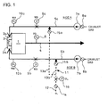
- FIG. 1 to 4 show the first embodiment of a method and an apparatus of controlling oxygen supply for a boiler of the invention.
- wind boxes 2a and 2b are disposed on left and right sides of a boiler body 1 and a burner 3 supplied with fuel in the boiler body 1 is arranged in the wind boxes 2a and 2b.
- An exhaust gas line 4 is connected to an output side of the boiler body 1 such that the exhaust gas may be emitted, and the wind boxes 2a and 2b on an input side of the boiler body 1 are connected to two recirculation gas lines 5a and 5b as separate systems corresponding to lateral sides (shown as sides A and B in Fig. 1 ), respectively.
- An oxygen concentration monitor 6 for detection of an oxygen concentration is incorporated in the exhaust gas line 4.
- the recirculation gas lines 5a and 5b may be connected to an atmosphere supply line (not shown) capable of introducing the atmosphere to the wind boxes 2a and 2b.
- the recirculation gas lines 5a and 5b have exhaust gas introduction dampers 8a and 8b such as adjustment dampers arranged adjacent to fans 7a and 7b so as to separately adjust the circulating exhaust gas flow rates into the wind boxes 2a and 2b, respectively.
- exhaust gas introduction dampers 8a and 8b such as adjustment dampers arranged adjacent to fans 7a and 7b so as to separately adjust the circulating exhaust gas flow rates into the wind boxes 2a and 2b, respectively.
- Incorporated in the recirculation gas lines 5a and 5b are left and right exhaust gas flowmeters 9a and 9b for detection of the left and right exhaust gas flow rates and left and right oxygen concentration monitors 10a and 10b for detection of the oxygen concentrations in the exhaust gas, respectively.
- the recirculation gas lines 5a and 5b are connected to an oxygen supply line 11 comprising a main supply line 12 on an oxygen supply source side and two connection supply lines 13a and 13b branched therefrom.
- the main supply line 12 of the oxygen supply line 11 has oxygen supplying means 14 such as a damper for adjustment of a total oxygen flow rate and an oxygen flowmeter 16 for detection of an oxygen supply flow rate.
- the connection supply lines 13a and 13b have oxygen distribution dampers 15a and 15b such as adjustment dampers for adjustment of the oxygen supply amounts to the recirculation gas lines 5a and 5b, respectively.
- all of the oxygen concentration monitor 6, the exhaust gas flowmeters 9a and 9b, the oxygen concentration monitors 10a and 10b and the oxygen flowmeter 16 are connected to a control unit (not shown) comprising processing means S1 for control of the oxygen supply amounts to the wind boxes 2a and 2b and processing means S2 for control of the exhaust gas flow rates to the wind boxes 2a and 2b so as to control the exhaust gas introduction and oxygen distribution dampers 8a, 8b, 15a and 15b based on signals of the exhaust gas flowmeters 9a and 9b, etc.
- the processing means S1 for control of the oxygen supply amount in the control unit comprises function generators 19a and 19b which output reference opening demands (reference opening degrees) 18a and 18b of the left and right oxygen distribution dampers 15a and 15b in accordance with a flow rate measurement signal (oxygen supply flow rate) 17 of the oxygen flowmeter 16; a subtractor 22 which obtains and outputs an oxygen concentration deviation 21 from concentration measurement signals (actually measured oxygen concentrations) 20a and 20b of the left and right oxygen concentration monitors 10a and 10b; a proportional integral adjuster 24 which executes a proportional integral process of the oxygen concentration deviation 21 from the subtractor 22 to output a control demand 23 for eliminating the oxygen concentration deviation; a manual/automatic operation device 25 switchable to output the control demand 23 from the proportional integral adjuster 24 through manual or automatic operation; and adders 28a and 28b which add a control demand 26 from the manual/automatic operation device 25 to the reference opening demands 18a and 18b from the function generators 19a and 19b to
- the processing means S2 for control of the exhaust gas flow rate in the control unit comprises a first processing unit S2a which calculates an exhaust gas flow rate set value from a boiler load demand and an actually measured exhaust gas flow rate and a second processing unit S2b which adds an actually measured oxygen concentration to the exhaust gas flow rate set value calculated by the first process.
- the first processing unit S2a comprises a flow rate function generator 31 which sets and outputs an exhaust gas flow rate set value 30 for the wind boxes 2a and 2b in accordance with a boiler load demand 29a; a concentration function generator 33 which sets and outputs an oxygen concentration set value 32 for the wind boxes 2a and 2b in accordance with a boiler load demand 29b; an average calculator 34 which obtains an average value to output a correction value 34a in accordance with the concentration measurement signals (actually measured oxygen concentrations) 20a and 20b of the left and right oxygen concentration monitors 10a and 10b; a switch 36 which terminates the usage of the average value for switching to output another correction value in accordance with a selection condition 35 in such a case that a difference is too large between left and right oxygen concentrations; a subtractor 38 which obtains and outputs an oxygen concentration set deviation 37 in accordance with the oxygen concentration set value 32 from the concentration function generator 33 and the correction value 34a from the switch 36; a proportional integral adjuster 40 which executes a proportional integral process of the oxygen
- the second processing unit S2b comprises a subtractor 56 which obtains and outputs an oxygen concentration deviation 55 from the concentration measurement signals (actually measured oxygen concentrations) 20a and 20b of the left and right oxygen concentration monitors 10a and 10b; a proportional integral adjuster 58 which executes a proportional integral process of the oxygen concentration deviation 55 from the subtractor 56 to output a control demand 57 for eliminating the oxygen concentration deviation; a manual/automatic operation device 59 switchable to output the control demand 57 from the proportional integral adjuster 58 through manual or automatic operation; and adders 62a and 62b which add a control demand 60 from the manual/automatic operation device 59 to the exhaust gas flow rate set value 53 from the first processing unit S2a to output corrective opening demands 61a and 61b. Exhaust gas introduction opening degrees of the left and right exhaust gas introduction dampers 8a and 8b are adjusted by the corrective opening demands 61a and 61b from the adders 62a and 62b, respectively.
- control unit When the exhaust gas is circulated in the boiler, the control unit, etc., control the oxygen supply amounts to the left and right wind boxes 2a and 2b and control the exhaust gas flow rates to the left and right wind boxes 2a and 2b.
- the oxygen flowmeter 16 of the oxygen supply line 11 measures the oxygen supply flow rate and sends the flow rate measurement signal 17 to the control unit (not shown) and the left and right oxygen concentration monitors 10a and 10b of the recirculation gas lines 5a and 5b respectively measure the oxygen concentrations and send the concentration measurement signals 20a and 20b to the control unit.
- the control unit obtains the reference opening demands (reference opening degrees) 18a and 18b of the left and right oxygen distribution dampers 15a and 15b via the function generators 19a and 19b through the flow rate measurement signal 17 to output the demands to the adders 28a and 28b.
- the oxygen concentration deviation 21 is obtained via subtractor 22 through the left and right concentration measurement signals 20a and 20b; the proportional integral adjuster 24 executes the process for eliminating the oxygen concentration deviation 21; and the control demand 26 for correction is output via the manual/automatic operation device 25 to the adders 28a and 28b.
- the left and right adders 28a and 28b add the control demand 26 for correction to the reference opening demands 18a and 18b to output the corrective opening demands 27a and 27b to control the oxygen supply opening degrees of the left and right oxygen distribution dampers 15a and 15b.
- the balance of the oxygen supply to the left and right wind boxes 2a and 2b is controlled based on the oxygen supply flow rate of the oxygen supply line 11 and the oxygen concentrations of the left and right recirculation gas lines 5a and 5b.
- the left and right exhaust gas flowmeters 9a and 9b of the recirculation gas lines 5a and 5b respectively measure the exhaust gas flow rates to send the exhaust gas measurement signals 47a and 47b to the control unit (not shown); and the left and right oxygen concentration monitors 10a and 10b of the recirculation gas lines 5a and 5b respectively measure the oxygen concentrations to send the concentration measurement signals 20a and 20b to the control unit.
- the first processing unit S2a of the control unit sets the exhaust gas flow rate set value 30 for the wind boxes 2a and 2b via the flow rate function generator 31 in accordance with the boiler load demand 29a to output the set value to the multiplier 44.
- the oxygen concentration set value 32 for the wind boxes 2a and 2b is set via the concentration function generator 33 in accordance with the boiler load demand 29b; an average value is obtained by the average calculator 34, etc., in accordance with the concentration measurement signals 20a and 20b of the left and right oxygen concentration monitors 10a and 10b and is output as the correction value 34a;
- the subtractor 38 obtains the oxygen concentration set deviation 37 in accordance with the oxygen concentration set value 32 and the correction value 34a;
- the proportional integral adjuster 40 executes the process for eliminating the oxygen concentration set deviation 37;
- the control demand 42 is output via the manual/automatic operation device 41 as a gain demand to the multiplier 44 and is output to the bias function generator 46.
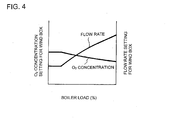
- the average value obtained from the concentration measurement signals 20a and 20b of the left and right oxygen concentration monitors 10a and 10b is applied as the correction value 34a from the average calculator 34 to the subtractor 38 and, if a difference is too large between left and right oxygen concentrations or if a combustion state is not appropriate, it is considered that the selection condition 35 is satisfied and the usage of the average value is terminated and switched to another predetermined value. If the boiler load demands 29a and 29b are given, a control program shown in Fig. 4 sets the oxygen concentrations for the wind boxes 2a and 2b and sets the flow rates of exhaust gas, etc., for the wind boxes 2a and 2b.
- the first processing unit S2a outputs the control demand from the bias function generator 46 as the bias demand 45 to the adder 48 and calculates the current data value 47 of the exhaust gas flow rate via the adder 48 in accordance with the exhaust gas measurement signals 47a and 47b of the left and right exhaust gas flowmeters 9a and 9b and output the current data value to the subtractor 50.
- the multiplier 44 multiplies the exhaust gas flow rate set value 30 from the flow rate function generator 31 by the control demand 42 as a gain demand to output the exhaust gas flow rate correction set value 43; the subtractor 50 obtains the exhaust gas flow rate set deviation 49 from the subtraction between the exhaust gas flow rate correction set value 43 and the exhaust gas flow rate current data value 47; the proportional integral adjuster 52 eliminates the exhaust gas flow rate set deviation 49 and outputs the exhaust gas flow rate control demand 51; and the adder 54 subsequently adds the exhaust gas flow rate control demand 51 and the bias demand 45 from the bias function generator 46 to output the exhaust gas flow rate set value 53.
- the second processing unit S2b obtains the oxygen concentration deviation 55 via the subtractor 56 from the left and right concentration measurement signals 20a and 20b, executes the process for eliminating the oxygen concentration deviation 55 with the proportional integral adjuster 58, and outputs the control demand 60 via the manual/automatic operation device 59 to the adders 62a and 62b.
- the adders 62a and 62b add the control demand 60 to the exhaust gas flow rate set value 53 from the first processing unit S2a to output the corrective opening demands 61a and 61b to control the exhaust gas introduction opening degrees of the left and right exhaust gas introduction dampers 8a and 8b.
- the left and right exhaust gases to the left and right wind boxes 2a and 2b are controlled based on the oxygen concentration set values corresponding to the boiler load demands 29a and 29b, the oxygen concentrations of the left and right recirculation gas lines 5a and 5b and the exhaust gas supply flow rates of the recirculation gas lines 5a and 5b.
- the left and right oxygen supply amounts are adjusted in accordance with the oxygen supply flow rate and the left and right actually measured oxygen concentrations to control the supply balance of oxygen and, when the exhaust gas flow rates are controlled, the left and right exhaust gas introductions are adjusted in accordance with the oxygen concentration set values corresponding to the boiler load demands 29a and 29b, the left and right actually measured exhaust gas flow rates and the left and right actually measured oxygen concentrations to control the exhaust gas flow rates and, therefore, unbalance may be constrained in the oxygen supply amounts and the exhaust gas flow rates introduced into the left and right wind boxes 2a and 2b to achieve steady combustion in the boiler body 1.
- the control unit when controlling the oxygen supply amounts, if the control unit is configured to measure the oxygen supply flow rate (flow rate measurement signal 17) with the oxygen flowmeter 16 to set the reference opening degrees (the reference opening demands 18a and 18b) with the left and right oxygen distribution dampers 15a and 15b depending on the oxygen supply flow rate, to measure the left and right actual oxygen concentrations (the concentration measurement signals 20a and 20b, the control demand 26) with the oxygen concentration monitors 10a and 10b, and to correct the reference opening degrees (the reference opening demands 18a and 18b) with the left and right oxygen distribution dampers 15a and 15b in accordance with the left and right actually measured oxygen concentrations to adjust the oxygen supply opening degrees, then the left and right oxygen supply amounts are properly adjusted to control the supply balance of oxygen when controlling the oxygen supply amounts, so that unbalance are further constrained in the oxygen supply amounts introduced into the left and right wind boxes 2a and 2b to achieve more steady combustion in the boiler body 1.
- the control unit when controlling the exhaust gas flow rates, if the control unit sets the exhaust gas flow rate set value 30 corresponding to the boiler load demand 29a, multiplies the exhaust gas flow rate set value 30 by the oxygen concentration set value 32 (the control demand 42) corresponding to the boiler load demand 29a, subtracts the left and right actually measured exhaust gas flow rates (the exhaust gas measurement signals 47a and 47b, the current data value 47) measured by the exhaust gas flowmeters 9a and 9b, adds the left and right actually measured oxygen concentrations (the concentration measurement signals 20a and 20b, the control demand 60) measured by the left and right oxygen concentration monitors 10a and 10b and adjusts the exhaust gas introduction opening degrees with the left and right exhaust gas introduction dampers 8a and 8b, then the left and right exhaust gas introductions are properly adjusted to control the exhaust gas flow rates when controlling the exhaust gas flow rates, so that the unbalance may be further constrained in the oxygen supply amounts and the exhaust gas flow rates into the left and right wind boxes 2a and 2b to achieve more steady combustion in the boiler body 1.
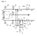
- FIG. 5 shows the second embodiment of a method and an apparatus of controlling oxygen supply for a boiler of the invention in which parts similar to those shown in Figs. 1 to 4 are represented by the same reference numerals.
- the apparatus of controlling oxygen supply for the boiler according to the second embodiment has a variation from the oxygen supply line 11 of the first embodiment.
- An oxygen supply line 71 of the second embodiment comprises a main supply line 12 and two connection supply lines 13a and 13b just like the first embodiment, and further comprises oxygen adjustment lines 72a and 72b branched from the main supply line 12 and connected to the left and right recirculation gas lines 5a and 5b.
- the main supply line 12 of the oxygen supply line 71 has oxygen supplying means 14 such as a damper for adjustment of a total oxygen flow rate and an oxygen flowmeter 16 for detection of an oxygen supply flow rate, and the two connection supply lines 13a and 13b respectively have oxygen distribution dampers 15a and 15b such as adjustment dampers to adjust the oxygen supply amounts to the recirculation gas lines 5a and 5b.
- oxygen supplying means 14 such as a damper for adjustment of a total oxygen flow rate and an oxygen flowmeter 16 for detection of an oxygen supply flow rate
- the two connection supply lines 13a and 13b respectively have oxygen distribution dampers 15a and 15b such as adjustment dampers to adjust the oxygen supply amounts to the recirculation gas lines 5a and 5b.
- the oxygen adjustment lines 72a and 72b of the oxygen supply line 71 have hand valves 73a and 73b as adjusting means, respectively.
- all of the oxygen concentration monitor 6, the exhaust gas flowmeters 9a and 9b, the oxygen concentration monitors 10a and 10b and the oxygen flowmeter 16 are connected to a control unit (not shown), and the control unit comprises processing means S1 (see Fig. 2 ) just like that of the first embodiment to control the oxygen supply amounts to the left and right wind boxes 2a and 2b and processing means S2 (see Fig. 3 ) just like that of the first embodiment to control the exhaust gas flow rates to the left and right wind boxes 2a and 2b so as to control the exhaust gas introduction and oxygen distribution dampers 8a, 8b, 15a and 15b based on signals of the exhaust gas flowmeters 9a and 9b, etc.
- the adjusting means may include other valves instead of the hand valves 73a and 73b so as to operate in association with the control unit.
- control unit When the exhaust gas is circulated in the boiler, the control unit, etc., control the oxygen supply amounts and the exhaust gas flow rates to the left and right wind boxes 2a and 2b as in the first embodiment to maintain the supply balance of oxygen to the left and right wind boxes 2a and 2b.
- a monitor or the like operates the hand valves 73a, 73b as adjusting means to control the oxygen from the oxygen adjustment lines 72a and 72b to finely tune the oxygen supply amounts of the recirculation gas lines 5a and 5b.
- the left and right exhaust gases to the left and right wind boxes 2a and 2b are properly controlled based on the oxygen concentration set values corresponding to the boiler load demands 29a and 29b, the oxygen concentrations of the left and right recirculation gas lines 5a and 5b and the exhaust gas supply flow rates of the recirculation gas lines 5a and 5b.
- the second embodiment includes the oxygen adjustment lines 72a, 72b branched from the oxygen supply line 71 and connected to the left and right recirculation gas lines 5a and 5b and the adjusting means such as hand valves 73a, 73b disposed in the oxygen adjustment lines 72a and 72b and the adjusting means are configured to control oxygen from the oxygen adjustment lines 72a, 72b to finely tune the oxygen supply amounts of the recirculation gas lines 5a and 5b, the oxygen supply amounts may easily be finely tuned even when the supply balance of the oxygen is slightly shifted.
- a monitor or the like may easily finely tune the oxygen supply amounts with the hand valves 73a and 73b as the adjusting means. Since the supply balance of oxygen may be completely achieved, the overall control is facilitated and the appearance may be improved.
Landscapes
- Engineering & Computer Science (AREA)
- Chemical & Material Sciences (AREA)
- Combustion & Propulsion (AREA)
- Mechanical Engineering (AREA)
- General Engineering & Computer Science (AREA)
- Physics & Mathematics (AREA)
- Thermal Sciences (AREA)
- Regulation And Control Of Combustion (AREA)
- Control Of Steam Boilers And Waste-Gas Boilers (AREA)
- Combustion Of Fluid Fuel (AREA)
- Air Supply (AREA)
Abstract
Description
- The present invention relates to a method and an apparatus of controlling oxygen supply for a boiler.
- Recently, in order to prevent global warming, it is desired to reduce emissions of greenhouse gases such as carbon dioxide and technologies are being developed for capturing carbon dioxide from combustion exhaust gas emitted from an oxyfuel combustion boiler for a storage process in ocean or in the underground formation.
- Such an oxyfuel combustion boiler includes an oxygen introduction line which introduces oxygen to an atmosphere supply line connected to a wind box on an input side of a boiler body, and a recirculation gas line branched from an exhaust gas line connected to an output side of the boiler body and connected to the atmosphere supply line. At a start-up, the air is introduced from the atmosphere supply line to the boiler body to burn fuel. After the completion of the start-up, dampers or the like arranged in the lines are switched to circulate an exhaust gas emitted from the boiler body through the recirculation gas line or the like to the boiler body; oxygen is introduced from the oxygen introduction line to the boiler body to perform the oxyfuel combustion of the fuel while constraining the lowering of oxygen concentration due to the recirculation gas to increase the carbon dioxide concentration in the exhaust gas and capture carbon dioxide from a portion of the exhaust gas.
- Such technique concerning a method and an apparatus of controlling oxygen supply for a boiler is disclosed, for example, in
Patent Literature 1. - [Patent Literature 1]
JP 2001-336736A - Such boiler facilities have wind boxes on left and right sides of a boiler body, and exhaust gas is circulated in such a manner that the exhaust gas from the recirculation gas line and oxygen from the oxygen introduction line are introduced through the atmosphere supply line to the left and right wind boxes for circulation of the exhaust gas, so that unbalance in oxygen supply amount and exhaust gas flow rate may occur between the left and right wind boxes, disadvantageously resulting in unsteady combustion in the boiler body.
- The invention was made in view of the above and has its object to provide a method and an apparatus of controlling oxygen supply for a boiler capable of constraining unbalance in oxygen supply amount and exhaust gas flow rate into wind boxes to achieve steady combustion in a boiler body.
- The invention provides a method of controlling oxygen supply for a boiler wherein, for wind boxes arranged on left and right of a boiler body, oxygen is supplied to the left and right sides with oxygen supply amounts being controlled respectively and exhaust gas is introduced to the left and right sides with exhaust gas flow rates being controlled respectively, comprising
controlling supply balance of oxygen by adjusting left and right oxygen supply amounts in accordance with an oxygen supply flow rate and left and right actually measured oxygen concentrations when controlling the oxygen supply amounts; and
controlling the exhaust gas flow rates by correcting an exhaust gas flow rate set value corresponding to a boiler load demand in accordance with an oxygen concentration set value corresponding to a boiler load demand, left and right actually measured exhaust gas flow rates and left and right actually measured oxygen concentrations and adjusting left and right exhaust gas introductions when controlling the exhaust gas flow rates. - In the method of controlling oxygen supply for the boiler and when controlling the oxygen supply amounts, preferably, the oxygen supply flow rate is measured; the left and right oxygen supply amounts are set in accordance with the oxygen supply flow rate; the left and right actual oxygen concentrations are measured; and the left and right oxygen supply amounts are corrected with the left and right actually measured oxygen concentrations.
- In the method of controlling oxygen supply for the boiler and when controlling the exhaust gas flow rates, preferably, an exhaust gas flow rate set value corresponding to a boiler load demand is set; an exhaust gas flow rate set amount is multiplied by an oxygen concentration set value corresponding to a boiler load demand; the left and right actually measured exhaust gas flow rates are subtracted; and the left and right actually measured oxygen concentrations are added to adjust the left and right exhaust gas introductions.
- On the other hand, the invention provides an apparatus of controlling oxygen supply for a boiler comprising wind boxes arranged on left and right of a boiler body, left and right recirculation gas lines for introduction of an exhaust gas to the left and right wind boxes, exhaust gas introduction dampers for adjustment of exhaust gas flow rates of the left and right recirculation gas lines, left and right exhaust gas flowmeters for detection of the exhaust gas flow rates.of the left and right recirculation gas lines, left and right oxygen concentration monitors for detection of oxygen concentrations of the left and right recirculation gas lines, an oxygen supply line for supply of oxygen to the left and right recirculation gas lines, an oxygen flowmeter for detection of a supply flow rate of oxygen supplied to the left and right recirculation gas lines, left and right oxygen distribution dampers for adjustment of oxygen supply amounts such that the left and right recirculation gas lines receive supply from the oxygen supply line, and a control unit for control of the exhaust gas introduction and oxygen distribution dampers,
wherein the control unit is configured to control supply balance of oxygen by adjusting oxygen supply opening degrees of the left and right oxygen distribution dampers in accordance with a oxygen supply flow rate and left and right actually measured oxygen concentrations when controlling the oxygen supply amounts and to control the exhaust gas flow rates by correcting an exhaust gas flow rate set value corresponding to a boiler load demand in accordance with an oxygen concentration set value corresponding to a boiler load demand, left and right actually measured exhaust gas flow rates and left and right actually measured oxygen concentrations and adjusting left and right exhaust gas introduction opening degrees of the left and right exhaust gas introduction dampers when controlling the exhaust gas flow rates. - In the apparatus of controlling oxygen supply for the boiler, preferably, the control units is configured to adjust the oxygen supply opening degrees by measuring the oxygen supply flow rate with the oxygen flow meter, setting reference opening degrees of the left and right oxygen distribution dampers in accordance with the oxygen supply flow, measuring the left and right actual oxygen concentrations with the oxygen concentration monitors and correcting the reference opening degrees of the left and right oxygen distribution dampers with the left and right actually measured oxygen concentrations when controlling the oxygen supply amounts.
- In apparatus of controlling the oxygen supply for the boiler, preferably, the control units sets an exhaust gas flow rate set amount corresponding to a boiler load demand, multiplies the exhaust gas flow rate set amount by an oxygen concentration set value corresponding to a boiler load demand, subtracts the left and right actual exhaust gas flow rates measured by the exhaust gas flowmeters and adds the left and right actual oxygen concentrations measured by the left and right oxygen concentration monitors to adjust the exhaust gas introduction opening degrees of the left and right exhaust gas introduction dampers when controlling the exhaust gas flow rates.
- Preferably, the apparatus of controlling oxygen supply for the boiler further comprises oxygen adjustment lines branched from the oxygen supply line and connected to the left and right recirculation gas lines and adjusting means disposed in the oxygen adjustment lines, wherein the adjusting means are configured to be capable of finely adjusting the oxygen supply amounts of the recirculation gas lines by controlling oxygen from the oxygen adjustment lines.
- In the method and the apparatus of controlling oxygen supply for the boiler, when the oxygen supply amounts are controlled for the left and right wind boxes, the left and right oxygen supply amounts are adjusted in accordance with the oxygen supply flow rate and the left and right actually measured oxygen concentrations to control the supply balance of oxygen and, when the exhaust gas flow rates are controlled, the left and right exhaust gas introductions are adjusted in accordance with the oxygen concentration set values corresponding to the boiler load demands, the left and right actually measured exhaust gas flow rates and the left and right actually measured oxygen concentrations to control the exhaust gas flow rates and, therefore, unbalance may be constrained in the oxygen supply amounts and the exhaust gas flow rates introduced into the left and right wind boxes to achieve steady combustion in the boiler body.
- According to a method and an apparatus of controlling oxygen supply for a boiler, an excellent effect may be achieved which may constrain unbalance in an oxygen supply amount and a exhaust gas flow rate introduced into left and right wind boxes to achieve steady combustion in a boiler body.
-
-
Fig. 1 is a conceptual diagram of a first embodiment of the invention; -
Fig. 2 is a control block diagram for control of an oxygen supply flow rate in the first embodiment of the invention; -
Fig. 3 is a control block diagram for control of an exhaust gas flow rate in the first embodiment of the invention; -
Fig. 4 is a line diagram of functions input to a function generator shown inFig. 3 ; and -
Fig. 5 is a conceptual diagram of a second embodiment of the invention. -
- 1
- boiler body
- 2a
- wind box
- 5a
- recirculation gas line
- 5b
- recirculation gas line
- 6
- oxygen concentration monitor
- 8a
- exhaust gas introduction damper
- 8b
- exhaust gas introduction damper
- 9a
- exhaust gas flowmeter
- 9b
- exhaust gas flowmeter
- 10a
- oxygen concentration monitor
- 10b
- oxygen concentration monitor
- 11
- oxygen supply line
- 15a
- oxygen distribution damper
- 15b
- oxygen distribution damper
- 16
- oxygen flowmeter
- 29a
- boiler load demand
- 29b
- boiler load demand
- 30
- exhaust gas flow rate set value
- 32
- oxygen concentration set value
- 71
- oxygen supply line
- 72a
- oxygen adjustment line
- 72b
- oxygen adjustment line
- 73a
- hand valve (adjusting means)
- 73b
- hand valve (adjusting means)
- A first embodiment of the invention will be described with reference to the accompanying drawings.
Figs. 1 to 4 show the first embodiment of a method and an apparatus of controlling oxygen supply for a boiler of the invention. - In the apparatus of controlling oxygen supply for the boiler of the first embodiment,
wind boxes boiler body 1 and aburner 3 supplied with fuel in theboiler body 1 is arranged in thewind boxes exhaust gas line 4 is connected to an output side of theboiler body 1 such that the exhaust gas may be emitted, and thewind boxes boiler body 1 are connected to tworecirculation gas lines Fig. 1 ), respectively. An oxygen concentration monitor 6 for detection of an oxygen concentration is incorporated in theexhaust gas line 4. Therecirculation gas lines wind boxes - The
recirculation gas lines gas introduction dampers 8a and 8b such as adjustment dampers arranged adjacent tofans wind boxes recirculation gas lines exhaust gas flowmeters - The
recirculation gas lines oxygen supply line 11 comprising amain supply line 12 on an oxygen supply source side and twoconnection supply lines main supply line 12 of theoxygen supply line 11 has oxygen supplying means 14 such as a damper for adjustment of a total oxygen flow rate and anoxygen flowmeter 16 for detection of an oxygen supply flow rate. Theconnection supply lines oxygen distribution dampers 15a and 15b such as adjustment dampers for adjustment of the oxygen supply amounts to therecirculation gas lines - On the other hand, all of the oxygen concentration monitor 6, the
exhaust gas flowmeters oxygen flowmeter 16 are connected to a control unit (not shown) comprising processing means S1 for control of the oxygen supply amounts to thewind boxes wind boxes oxygen distribution dampers exhaust gas flowmeters - As shown in
Fig. 2 , the processing means S1 for control of the oxygen supply amount in the control unit comprises function generators 19a and 19b which output reference opening demands (reference opening degrees) 18a and 18b of the left and rightoxygen distribution dampers 15a and 15b in accordance with a flow rate measurement signal (oxygen supply flow rate) 17 of theoxygen flowmeter 16; asubtractor 22 which obtains and outputs anoxygen concentration deviation 21 from concentration measurement signals (actually measured oxygen concentrations) 20a and 20b of the left and right oxygen concentration monitors 10a and 10b; a proportionalintegral adjuster 24 which executes a proportional integral process of theoxygen concentration deviation 21 from thesubtractor 22 to output acontrol demand 23 for eliminating the oxygen concentration deviation; a manual/automatic operation device 25 switchable to output thecontrol demand 23 from the proportionalintegral adjuster 24 through manual or automatic operation; andadders control demand 26 from the manual/automatic operation device 25 to the reference opening demands 18a and 18b from the function generators 19a and 19b to output corrective opening demands 27a and 27b, respectively. Oxygen supply opening degrees of the left and rightoxygen distribution dampers 15a and 15b are adjusted by the corrective opening demands 27a and 27b from theadder - On the other hand, as shown in
Fig. 3 , the processing means S2 for control of the exhaust gas flow rate in the control unit comprises a first processing unit S2a which calculates an exhaust gas flow rate set value from a boiler load demand and an actually measured exhaust gas flow rate and a second processing unit S2b which adds an actually measured oxygen concentration to the exhaust gas flow rate set value calculated by the first process. - The first processing unit S2a comprises a flow rate function generator 31 which sets and outputs an exhaust gas flow rate set value 30 for the wind boxes 2a and 2b in accordance with a boiler load demand 29a; a concentration function generator 33 which sets and outputs an oxygen concentration set value 32 for the wind boxes 2a and 2b in accordance with a boiler load demand 29b; an average calculator 34 which obtains an average value to output a correction value 34a in accordance with the concentration measurement signals (actually measured oxygen concentrations) 20a and 20b of the left and right oxygen concentration monitors 10a and 10b; a switch 36 which terminates the usage of the average value for switching to output another correction value in accordance with a selection condition 35 in such a case that a difference is too large between left and right oxygen concentrations; a subtractor 38 which obtains and outputs an oxygen concentration set deviation 37 in accordance with the oxygen concentration set value 32 from the concentration function generator 33 and the correction value 34a from the switch 36; a proportional integral adjuster 40 which executes a proportional integral process of the oxygen concentration set deviation 37 from the subtractor 38 to output a control demand 39 for eliminating the deviation; a manual/automatic operation device 41 switchable to output the control demand 39 from the proportional integral adjuster 40 through manual or automatic operation; a multiplier 44 which multiplies the left and right exhaust gas flow rate set value 30 from the flow rate function generator 31 by a control demand 42 from the manual/automatic operation device 41 as a gain demand to output an exhaust gas flow rate correction set value 43; a bias function generator 46 which outputs the control demand 42 from the manual/automatic operation device 41 as a bias demand 45; an adder 48 which adds exhaust gas measurement signals (actually measured exhaust gas flow rates) 47a and 47b of the left and right exhaust gas flowmeters 9a and 9b to output a current data value 47 of the exhaust gas flow rate; an subtractor 50 which obtains and outputs an exhaust gas flow rate set deviation 49 from the exhaust gas flow rate correction set value 43 from the multiplier 44 and the current data value 47 from the adder 48; a proportional integral adjuster 52 which executes a proportional integral process of the exhaust gas flow rate set deviation 49 from the subtractor 50 to output an exhaust gas flow rate control demand 51 for eliminating the exhaust gas flow rate set deviation; and an adder 54 which adds the exhaust gas flow rate control demand 51 from the proportional integral adjuster 52 and the bias demand 45 from the bias function generator 46 to output an exhaust gas flow rate set value 53.
- The second processing unit S2b comprises a
subtractor 56 which obtains and outputs anoxygen concentration deviation 55 from the concentration measurement signals (actually measured oxygen concentrations) 20a and 20b of the left and right oxygen concentration monitors 10a and 10b; a proportionalintegral adjuster 58 which executes a proportional integral process of theoxygen concentration deviation 55 from thesubtractor 56 to output acontrol demand 57 for eliminating the oxygen concentration deviation; a manual/automatic operation device 59 switchable to output thecontrol demand 57 from the proportionalintegral adjuster 58 through manual or automatic operation; andadders control demand 60 from the manual/automatic operation device 59 to the exhaust gas flow rate setvalue 53 from the first processing unit S2a to output corrective opening demands 61a and 61b. Exhaust gas introduction opening degrees of the left and right exhaustgas introduction dampers 8a and 8b are adjusted by the corrective opening demands 61a and 61b from theadders - The operation of the first embodiment of the invention will be described.
- When the exhaust gas is circulated in the boiler, the control unit, etc., control the oxygen supply amounts to the left and
right wind boxes right wind boxes - Specifically, when the oxygen supply amounts to the left and
right wind boxes oxygen flowmeter 16 of theoxygen supply line 11 measures the oxygen supply flow rate and sends the flowrate measurement signal 17 to the control unit (not shown) and the left and right oxygen concentration monitors 10a and 10b of therecirculation gas lines concentration measurement signals Fig. 2 , the control unit obtains the reference opening demands (reference opening degrees) 18a and 18b of the left and rightoxygen distribution dampers 15a and 15b via the function generators 19a and 19b through the flowrate measurement signal 17 to output the demands to theadders oxygen concentration deviation 21 is obtained viasubtractor 22 through the left and rightconcentration measurement signals integral adjuster 24 executes the process for eliminating theoxygen concentration deviation 21; and thecontrol demand 26 for correction is output via the manual/automatic operation device 25 to theadders right adders control demand 26 for correction to the reference opening demands 18a and 18b to output the corrective opening demands 27a and 27b to control the oxygen supply opening degrees of the left and rightoxygen distribution dampers 15a and 15b. - As a result, the balance of the oxygen supply to the left and
right wind boxes oxygen supply line 11 and the oxygen concentrations of the left and rightrecirculation gas lines - On the other hand, as shown in
Fig. 3 , when the exhaust gas flow rates to the left andright wind boxes exhaust gas flowmeters recirculation gas lines gas measurement signals recirculation gas lines concentration measurement signals - The first processing unit S2a of the control unit sets the exhaust gas flow rate set
value 30 for thewind boxes rate function generator 31 in accordance with theboiler load demand 29a to output the set value to themultiplier 44. Concurrently, the oxygen concentration setvalue 32 for thewind boxes concentration function generator 33 in accordance with theboiler load demand 29b; an average value is obtained by theaverage calculator 34, etc., in accordance with theconcentration measurement signals correction value 34a; thesubtractor 38 obtains the oxygen concentration setdeviation 37 in accordance with the oxygen concentration setvalue 32 and thecorrection value 34a; the proportionalintegral adjuster 40 executes the process for eliminating the oxygen concentration setdeviation 37; and thecontrol demand 42 is output via the manual/automatic operation device 41 as a gain demand to themultiplier 44 and is output to thebias function generator 46. In a usual case, the average value obtained from theconcentration measurement signals correction value 34a from theaverage calculator 34 to thesubtractor 38 and, if a difference is too large between left and right oxygen concentrations or if a combustion state is not appropriate, it is considered that theselection condition 35 is satisfied and the usage of the average value is terminated and switched to another predetermined value. If the boiler load demands 29a and 29b are given, a control program shown inFig. 4 sets the oxygen concentrations for thewind boxes wind boxes - The first processing unit S2a outputs the control demand from the
bias function generator 46 as thebias demand 45 to the adder 48 and calculates thecurrent data value 47 of the exhaust gas flow rate via the adder 48 in accordance with the exhaustgas measurement signals exhaust gas flowmeters subtractor 50. Themultiplier 44 multiplies the exhaust gas flow rate setvalue 30 from the flowrate function generator 31 by thecontrol demand 42 as a gain demand to output the exhaust gas flow rate correction setvalue 43; thesubtractor 50 obtains the exhaust gas flow rate setdeviation 49 from the subtraction between the exhaust gas flow rate correction setvalue 43 and the exhaust gas flow ratecurrent data value 47; the proportionalintegral adjuster 52 eliminates the exhaust gas flow rate setdeviation 49 and outputs the exhaust gas flowrate control demand 51; and theadder 54 subsequently adds the exhaust gas flowrate control demand 51 and thebias demand 45 from thebias function generator 46 to output the exhaust gas flow rate setvalue 53. - The second processing unit S2b obtains the
oxygen concentration deviation 55 via thesubtractor 56 from the left and rightconcentration measurement signals oxygen concentration deviation 55 with the proportionalintegral adjuster 58, and outputs thecontrol demand 60 via the manual/automatic operation device 59 to theadders adders control demand 60 to the exhaust gas flow rate setvalue 53 from the first processing unit S2a to output the corrective opening demands 61a and 61b to control the exhaust gas introduction opening degrees of the left and right exhaustgas introduction dampers 8a and 8b. - As a result, the left and right exhaust gases to the left and
right wind boxes recirculation gas lines recirculation gas lines - As above, according to the first embodiment, when the oxygen supply amounts are controlled for the left and
right wind boxes right wind boxes boiler body 1. - In the first embodiment, when controlling the oxygen supply amounts, if the control unit is configured to measure the oxygen supply flow rate (flow rate measurement signal 17) with the
oxygen flowmeter 16 to set the reference opening degrees (the reference opening demands 18a and 18b) with the left and rightoxygen distribution dampers 15a and 15b depending on the oxygen supply flow rate, to measure the left and right actual oxygen concentrations (theconcentration measurement signals oxygen distribution dampers 15a and 15b in accordance with the left and right actually measured oxygen concentrations to adjust the oxygen supply opening degrees, then the left and right oxygen supply amounts are properly adjusted to control the supply balance of oxygen when controlling the oxygen supply amounts, so that unbalance are further constrained in the oxygen supply amounts introduced into the left andright wind boxes boiler body 1. - In the first embodiment, when controlling the exhaust gas flow rates, if the control unit sets the exhaust gas flow rate set
value 30 corresponding to theboiler load demand 29a, multiplies the exhaust gas flow rate setvalue 30 by the oxygen concentration set value 32 (the control demand 42) corresponding to theboiler load demand 29a, subtracts the left and right actually measured exhaust gas flow rates (the exhaustgas measurement signals exhaust gas flowmeters concentration measurement signals gas introduction dampers 8a and 8b, then the left and right exhaust gas introductions are properly adjusted to control the exhaust gas flow rates when controlling the exhaust gas flow rates, so that the unbalance may be further constrained in the oxygen supply amounts and the exhaust gas flow rates into the left andright wind boxes boiler body 1. - Hereinafter, a second embodiment of the present invention will be described with reference to the accompanying drawings.
Fig. 5 shows the second embodiment of a method and an apparatus of controlling oxygen supply for a boiler of the invention in which parts similar to those shown inFigs. 1 to 4 are represented by the same reference numerals. - The apparatus of controlling oxygen supply for the boiler according to the second embodiment has a variation from the
oxygen supply line 11 of the first embodiment. Anoxygen supply line 71 of the second embodiment comprises amain supply line 12 and twoconnection supply lines oxygen adjustment lines main supply line 12 and connected to the left and rightrecirculation gas lines - As in the first embodiment, the
main supply line 12 of theoxygen supply line 71 has oxygen supplying means 14 such as a damper for adjustment of a total oxygen flow rate and anoxygen flowmeter 16 for detection of an oxygen supply flow rate, and the twoconnection supply lines oxygen distribution dampers 15a and 15b such as adjustment dampers to adjust the oxygen supply amounts to therecirculation gas lines - The
oxygen adjustment lines oxygen supply line 71 havehand valves - As in the first embodiment, in the configuration of the second embodiment, all of the oxygen concentration monitor 6, the
exhaust gas flowmeters oxygen flowmeter 16 are connected to a control unit (not shown), and the control unit comprises processing means S1 (seeFig. 2 ) just like that of the first embodiment to control the oxygen supply amounts to the left andright wind boxes Fig. 3 ) just like that of the first embodiment to control the exhaust gas flow rates to the left andright wind boxes oxygen distribution dampers exhaust gas flowmeters hand valves - The operation of the second embodiment of the invention will be described.
- When the exhaust gas is circulated in the boiler, the control unit, etc., control the oxygen supply amounts and the exhaust gas flow rates to the left and
right wind boxes right wind boxes - The supply balance of oxygen may not be complete and may have slight shift for various reasons. In this case, a monitor or the like operates the
hand valves oxygen adjustment lines recirculation gas lines - As a result, the left and right exhaust gases to the left and
right wind boxes recirculation gas lines recirculation gas lines - As above, according to the second embodiment, the same operational effect as the first embodiment can be acquired.
- When the second embodiment includes the
oxygen adjustment lines oxygen supply line 71 and connected to the left and rightrecirculation gas lines hand valves oxygen adjustment lines oxygen adjustment lines recirculation gas lines hand valves - It is to be understood that a method and an apparatus of controlling oxygen supply for a boiler according to the invention is not limited to the above embodiments and that various changes and modifications may be made without departing from the scope of the invention.
Claims (7)
- A method of controlling oxygen supply for a boiler wherein, for wind boxes arranged on left and right of a boiler body, oxygen is supplied to the left and right sides with oxygen supply amounts being controlled respectively and exhaust gas is introduced to the left and right sides with exhaust gas flow rates being controlled respectively, comprising
controlling supply balance of oxygen by adjusting left and right oxygen supply amounts in accordance with an oxygen supply flow rate and left and right actually measured oxygen concentrations when controlling the oxygen supply amounts; and
controlling the exhaust gas flow rates by correcting an exhaust gas flow rate set value corresponding to a boiler load demand in accordance with an oxygen concentration set value corresponding to the boiler load demand, left and right actually measured exhaust gas flow rates and left and right actually measured oxygen concentrations and adjusting left and right exhaust gas introductions when controlling the exhaust gas flow rates. - A method of controlling oxygen supply for a boiler as claimed in claim 1, wherein when controlling the oxygen supply amounts, the oxygen supply flow rate is measured; the left and right oxygen supply amounts are set in accordance with the oxygen supply flow rate; the left and right actual oxygen concentrations are measured; and the left and right oxygen supply amounts are corrected with the left and right actually measured oxygen concentrations.
- A method of controlling oxygen supply for a boiler as claimed in claim 1, wherein when controlling the exhaust gas flow rates, an exhaust gas flow rate set value corresponding to a boiler load demand is set; an exhaust gas flow rate set amount is multiplied by an oxygen concentration set value corresponding to a boiler load demand; the left and right actually measured exhaust gas flow rates are subtracted; and the left and right actually measured oxygen concentrations are.added to adjust.the left and right exhaust gas introductions.
- An apparatus of controlling oxygen supply for a boiler comprising wind boxes arranged on left and right of a boiler body, left and right recirculation gas lines for introduction of an exhaust gas to the left and right wind boxes, exhaust gas introduction dampers for adjustment of exhaust gas flow rates of the left and right recirculation gas lines, left and right exhaust gas flowmeters for detection of the exhaust gas flow rates of the left and right recirculation gas lines, left and right oxygen concentration monitors for detection of oxygen concentrations of the left and right recirculation gas lines, an oxygen supply line for supply of oxygen to the left and right recirculation gas lines, an oxygen flowmeter for detection of a supply flow rate of oxygen supplied to the left and right recirculation gas lines, left and right oxygen distribution dampers for adjustment of oxygen supply amounts such that the left and right recirculation gas lines receive supply from the oxygen supply line, and a control unit for control of the exhaust gas introduction and oxygen distribution dampers,
wherein the control unit is configured to control supply balance of oxygen by adjusting oxygen supply opening degrees of the left and right oxygen distribution dampers in accordance with a oxygen supply flow rate and left and right actually measured oxygen concentrations when controlling the oxygen supply amounts and to control the exhaust gas flow rates by correcting an exhaust gas flow rate set value corresponding to a boiler load demand in accordance with an oxygen concentration set value corresponding to a boiler load demand, left and right actually measured exhaust gas flow rates and left and right actually measured oxygen concentrations and adjusting left and right exhaust gas introduction opening degrees of the left and right exhaust gas introduction dampers when controlling the exhaust gas flow rates. - An apparatus of controlling oxygen supply for a boiler as claimed in claim 4, wherein the control units is configured to adjust the oxygen supply opening degrees by measuring the oxygen supply flow rate with the oxygen flow meter, setting reference opening degrees of the left and right oxygen distribution dampers in accordance with the oxygen supply flow rate, measuring the left and right actual oxygen concentrations with the oxygen concentration monitors and correcting the reference opening degrees of the left and right oxygen distribution dampers with the left and right actually measured oxygen concentrations when controlling the oxygen supply amounts.
- An apparatus of controlling oxygen supply for a boiler as claimed in claim 4, wherein the control units sets an exhaust gas flow rate set amount corresponding to a boiler load demand, multiplies the exhaust gas flow rate set amount by an oxygen concentration set value corresponding to a boiler load demand, subtracts the left and right actual exhaust gas flow rates measured by the exhaust gas flowmeters and adds the left and right actual oxygen concentrations measured by the left and right oxygen concentration monitors to adjust the exhaust gas introduction opening degrees of the left and right exhaust gas introduction dampers when controlling the exhaust gas flow rates.
- An apparatus of controlling oxygen supply for a boiler as claimed in claim 4, further comprises oxygen adjustment lines branched from the oxygen supply line and connected to the left and right recirculation gas lines and adjusting means disposed in the oxygen adjustment lines, wherein the adjusting means are configured to be capable of finely adjusting the oxygen supply amounts of"the recirculation gas lines by controlling oxygen from the oxygen adjustment lines.
Priority Applications (1)
| Application Number | Priority Date | Filing Date | Title |
|---|---|---|---|
| PL08720356T PL2251597T3 (en) | 2008-03-06 | 2008-03-06 | Method and apparatus of controlling oxygen supply for boiler |
Applications Claiming Priority (1)
| Application Number | Priority Date | Filing Date | Title |
|---|---|---|---|
| PCT/JP2008/000470 WO2009110032A1 (en) | 2008-03-06 | 2008-03-06 | Method of controlling oxygen supply in boiler and apparatus therefor |
Publications (3)
| Publication Number | Publication Date |
|---|---|
| EP2251597A1 true EP2251597A1 (en) | 2010-11-17 |
| EP2251597A4 EP2251597A4 (en) | 2012-06-06 |
| EP2251597B1 EP2251597B1 (en) | 2013-05-22 |
Family
ID=41055614
Family Applications (1)
| Application Number | Title | Priority Date | Filing Date |
|---|---|---|---|
| EP08720356.8A Active EP2251597B1 (en) | 2008-03-06 | 2008-03-06 | Method and apparatus of controlling oxygen supply for boiler |
Country Status (8)
| Country | Link |
|---|---|
| US (1) | US8662884B2 (en) |
| EP (1) | EP2251597B1 (en) |
| JP (1) | JP5214721B2 (en) |
| CN (1) | CN102016416B (en) |
| AU (1) | AU2008352208B2 (en) |
| ES (1) | ES2420558T3 (en) |
| PL (1) | PL2251597T3 (en) |
| WO (1) | WO2009110032A1 (en) |
Cited By (1)
| Publication number | Priority date | Publication date | Assignee | Title |
|---|---|---|---|---|
| CN103299129A (en) * | 2011-01-17 | 2013-09-11 | 株式会社Ihi | Method and device for controlling operation of oxygen combustion boiler |
Families Citing this family (5)
| Publication number | Priority date | Publication date | Assignee | Title |
|---|---|---|---|---|
| CN103225820B (en) * | 2013-05-13 | 2015-05-13 | 北京和隆优化科技股份有限公司 | Chain grate furnace combustion optimization control system |
| JP6163994B2 (en) * | 2013-09-18 | 2017-07-19 | 株式会社Ihi | Oxygen combustion boiler exhaust gas cooler steam generation prevention device |
| JP6537987B2 (en) * | 2016-02-01 | 2019-07-03 | 住友重機械工業株式会社 | Combustion control system and combustion control method |
| KR101727257B1 (en) | 2016-09-09 | 2017-04-14 | 주식회사 지스코 | Boiler equipment and operating method thereof |
| KR20260032619A (en) * | 2023-07-19 | 2026-03-09 | 에어 프로덕츠 앤드 케미칼스, 인코오포레이티드 | Control system for steam reforming device and control process for steam reforming device |
Family Cites Families (48)
| Publication number | Priority date | Publication date | Assignee | Title |
|---|---|---|---|---|
| US1098247A (en) * | 1909-12-10 | 1914-05-26 | George James Gibbs | Apparatus for indicating or measuring the rate of flow of fluid through pipes, or for detecting leakage. |
| US3481538A (en) * | 1968-05-02 | 1969-12-02 | Elliott Brothers London Ltd | Boiler control apparatus |
| US3998097A (en) * | 1975-03-17 | 1976-12-21 | Mitsubishi Jukogyo Kabushiki Kaisha | Flow-measuring device |
| JPS55131625A (en) * | 1979-03-30 | 1980-10-13 | Sumitomo Metal Ind Ltd | Combution control method |
| JPS5623615A (en) * | 1979-08-06 | 1981-03-06 | Babcock Hitachi Kk | Burning method for low nox |
| JPS6115957A (en) * | 1984-06-30 | 1986-01-24 | Kawasaki Steel Corp | Alloying furnace for galvanizing |
| JPS6127410A (en) * | 1984-07-18 | 1986-02-06 | Babcock Hitachi Kk | Combustion apparatus |
| JPS63306309A (en) * | 1987-06-04 | 1988-12-14 | Ishikawajima Harima Heavy Ind Co Ltd | Air flow rate controlling system for boiler |
| JPH076153B2 (en) * | 1989-01-19 | 1995-01-30 | 日本製紙株式会社 | Boiler combustion control device |
| US4926698A (en) * | 1989-03-03 | 1990-05-22 | Process Automation Business, Inc. | Dual wedge flow element |
| CS236689A2 (en) * | 1989-04-17 | 1991-09-15 | Poludniowy Okreg Energetycny K | Method of combustion process automatic optimization in heating installations and equipment for this method realization |
| US5044287A (en) * | 1989-06-16 | 1991-09-03 | Ebara Corporation | Method of controlling combustion in a fluidized bed furnace |
| EP0498809B2 (en) * | 1989-10-30 | 1997-10-29 | Honeywell Inc. | combustion control |
| JPH04244504A (en) | 1991-01-30 | 1992-09-01 | Central Res Inst Of Electric Power Ind | Carbon dioxide recovery type coal thermal power system |
| JP3053914B2 (en) | 1991-07-16 | 2000-06-19 | バブコック日立株式会社 | CO2 recovery boiler |
| JP3038073B2 (en) | 1991-12-20 | 2000-05-08 | 電源開発株式会社 | How to reduce N2O in fluidized bed boilers |
| JP3181649B2 (en) | 1991-12-20 | 2001-07-03 | 電源開発株式会社 | Boiler carbon dioxide capture device |
| JPH06137514A (en) * | 1992-10-28 | 1994-05-17 | Sumitomo Metal Ind Ltd | Method for producing high-concentration carbon dioxide |
| JP3338555B2 (en) | 1994-05-24 | 2002-10-28 | 電源開発株式会社 | Combustion burner for carbon dioxide recovery type exhaust gas recirculation boiler equipment |
| JP3777470B2 (en) * | 1995-11-15 | 2006-05-24 | バブコック日立株式会社 | Exhaust gas mixing device |
| JPH11281007A (en) * | 1998-03-31 | 1999-10-15 | Chugai Ro Co Ltd | Operation method of batch type furnace |
| US6203187B1 (en) * | 1998-08-06 | 2001-03-20 | Institute Of Gas Technology | Method and apparatus for controlled mixing of fluids |
| JP2000065305A (en) * | 1998-08-20 | 2000-03-03 | Hitachi Ltd | Once-through boiler |
| US6289266B1 (en) * | 1999-05-14 | 2001-09-11 | Allegheny Power Service Corporation | Method of operating a boiler |
| US6279495B1 (en) * | 1999-10-22 | 2001-08-28 | Pulp And Paper Research Institute Of Canada | Method and apparatus for optimizing the combustion air system in a recovery boiler |
| US6612186B1 (en) * | 2000-02-16 | 2003-09-02 | Micro Motion, Inc. | Mass fraction metering device |
| JP2001235103A (en) | 2000-02-21 | 2001-08-31 | Babcock Hitachi Kk | Oxygen burning boiler and its operating method |
| JP4161515B2 (en) * | 2000-05-30 | 2008-10-08 | 株式会社Ihi | Exhaust gas oxygen concentration control method and apparatus for oxyfuel boiler equipment |
| JP2002206736A (en) * | 2001-01-09 | 2002-07-26 | Babcock Hitachi Kk | Boiler and combustion method therefor |
| US6619041B2 (en) * | 2001-06-29 | 2003-09-16 | L'air Liquide - Societe Anonyme A Directoire Et Conseil De Surveillance Pour L'etude Et L'exploitation Des Procedes Georges Claude | Steam generation apparatus and methods |
| US6935251B2 (en) * | 2002-02-15 | 2005-08-30 | American Air Liquide, Inc. | Steam-generating combustion system and method for emission control using oxygen enhancement |
| JP4174311B2 (en) * | 2002-12-12 | 2008-10-29 | バブコック日立株式会社 | Combustion device and wind box |
| US8246343B2 (en) * | 2003-01-21 | 2012-08-21 | L'air Liquide Societe Anonyme Pour L'etude Et L'exploitation Des Procedes Georges Claude | Device and method for efficient mixing of two streams |
| US7401577B2 (en) * | 2003-03-19 | 2008-07-22 | American Air Liquide, Inc. | Real time optimization and control of oxygen enhanced boilers |
| US6843185B1 (en) * | 2003-06-27 | 2005-01-18 | Maxon Corporation | Burner with oxygen and fuel mixing apparatus |
| JP3986485B2 (en) * | 2003-09-29 | 2007-10-03 | 株式会社日立製作所 | Boiler control device and boiler control method |
| EP1798385B1 (en) * | 2004-10-05 | 2016-03-23 | JGC Corporation | Integrated gasification combined cycle and method of controlling thereof |
| AU2005229668B2 (en) * | 2004-11-04 | 2008-03-06 | Babcock-Hitachi K.K. | Overfiring air port, method for manufacturing air port, boiler, boiler facility, method for operating boiler facility and method for improving boiler facility |
| US7516620B2 (en) * | 2005-03-01 | 2009-04-14 | Jupiter Oxygen Corporation | Module-based oxy-fuel boiler |
| JP4554440B2 (en) * | 2005-06-02 | 2010-09-29 | 日揮株式会社 | Gasification combined power generation facility and control method thereof |
| US7950217B2 (en) * | 2005-08-12 | 2011-05-31 | American Air Liquide, Inc. | Oxygen-enriched air assisting system for improving the efficiency of cogeneration system |
| JP4731293B2 (en) * | 2005-11-28 | 2011-07-20 | 電源開発株式会社 | Combustion control method and apparatus for oxyfuel boiler |
| JP2007147161A (en) * | 2005-11-28 | 2007-06-14 | Electric Power Dev Co Ltd | Exhaust gas disposal method and apparatus for combustion apparatus |
| US8505472B2 (en) * | 2006-01-11 | 2013-08-13 | Babcock-Hitachi K.K. | Pulverized coal-fired boiler and pulverized coal burning method |
| US20080156236A1 (en) * | 2006-12-20 | 2008-07-03 | Osamu Ito | Pulverized coal combustion boiler |
| US8015932B2 (en) * | 2007-09-24 | 2011-09-13 | General Electric Company | Method and apparatus for operating a fuel flexible furnace to reduce pollutants in emissions |
| JP4644725B2 (en) * | 2008-05-07 | 2011-03-02 | 株式会社日立製作所 | Oxy-combustion boiler system, pulverized-coal-fired boiler remodeling method, oxy-combustion boiler system control device |
| JP5174618B2 (en) * | 2008-10-31 | 2013-04-03 | 株式会社日立製作所 | Oxyfuel combustion boiler system and control method for oxygen combustion boiler system |
-
2008
- 2008-03-06 ES ES08720356T patent/ES2420558T3/en active Active
- 2008-03-06 EP EP08720356.8A patent/EP2251597B1/en active Active
- 2008-03-06 PL PL08720356T patent/PL2251597T3/en unknown
- 2008-03-06 CN CN2008801290358A patent/CN102016416B/en active Active
- 2008-03-06 AU AU2008352208A patent/AU2008352208B2/en active Active
- 2008-03-06 US US12/920,686 patent/US8662884B2/en active Active
- 2008-03-06 WO PCT/JP2008/000470 patent/WO2009110032A1/en not_active Ceased
- 2008-03-06 JP JP2010501684A patent/JP5214721B2/en active Active
Cited By (3)
| Publication number | Priority date | Publication date | Assignee | Title |
|---|---|---|---|---|
| CN103299129A (en) * | 2011-01-17 | 2013-09-11 | 株式会社Ihi | Method and device for controlling operation of oxygen combustion boiler |
| CN103299129B (en) * | 2011-01-17 | 2015-08-26 | 株式会社Ihi | The method for controlling of operation of oxygen combustion boiler and device |
| EP2667093A4 (en) * | 2011-01-17 | 2017-06-07 | IHI Corporation | Method and device for controlling operation of oxygen combustion boiler |
Also Published As
| Publication number | Publication date |
|---|---|
| JPWO2009110032A1 (en) | 2011-07-14 |
| US20110045421A1 (en) | 2011-02-24 |
| AU2008352208B2 (en) | 2012-05-17 |
| EP2251597B1 (en) | 2013-05-22 |
| CN102016416A (en) | 2011-04-13 |
| AU2008352208A1 (en) | 2009-09-11 |
| EP2251597A4 (en) | 2012-06-06 |
| ES2420558T3 (en) | 2013-08-23 |
| US8662884B2 (en) | 2014-03-04 |
| CN102016416B (en) | 2012-10-03 |
| JP5214721B2 (en) | 2013-06-19 |
| PL2251597T3 (en) | 2013-10-31 |
| WO2009110032A1 (en) | 2009-09-11 |
Similar Documents
| Publication | Publication Date | Title |
|---|---|---|
| EP2251597B1 (en) | Method and apparatus of controlling oxygen supply for boiler | |
| KR101520240B1 (en) | Valve control device, gas turbine, and valve control method | |
| JP5970368B2 (en) | Boiler control device | |
| JPWO2014132932A1 (en) | Gas turbine system, control device, and operation method of gas turbine | |
| KR101770534B1 (en) | Control device and control method | |
| US10815905B2 (en) | Fuel control method for gas turbine, control device for executing said method, and gas turbine installation provided with said control device | |
| JP5595221B2 (en) | Gas turbine control device, gas turbine, and gas turbine control method | |
| JP2011157860A (en) | Mixed combustion system | |
| JP2004190913A (en) | Automatic correction device of calorific value in coal-fired boiler | |
| JP5314946B2 (en) | Heating furnace controller | |
| KR100936187B1 (en) | Oxygen Concentration Control Method | |
| KR101143728B1 (en) | Automatic control device for NOx concentration and method thereof | |
| JP4627509B2 (en) | Plant control apparatus and plant control method | |
| KR101752110B1 (en) | Gas turbine plant, control device thereof, and gas turbine operation method | |
| JPH0280511A (en) | Method for controlling dew point of atmospheric gas in furnace | |
| JP3817851B2 (en) | Fuel gas pressure control method and apparatus for gas fired boiler | |
| KR100689150B1 (en) | Boiler air-fuel ratio multiple control system | |
| JP2014159886A (en) | Boiler system | |
| JP2011111952A (en) | Power plant and operating method of the same | |
| CN121383446A (en) | Combustion control method, device, equipment and storage medium of gas water heater | |
| JP2007085682A (en) | Boiler for thermal power generation, and combustion air supply control method | |
| JPH0526425A (en) | Method of controlling combustion air amount in ash melting furnace | |
| JP2009162424A (en) | Low pressure steam supply device | |
| JP2015210007A (en) | Control apparatus and control method for mixed gas fuel production facility | |
| JPH04131611A (en) | Co/o2 controller |
Legal Events
| Date | Code | Title | Description |
|---|---|---|---|
| PUAI | Public reference made under article 153(3) epc to a published international application that has entered the european phase |
Free format text: ORIGINAL CODE: 0009012 |
|
| 17P | Request for examination filed |
Effective date: 20100826 |
|
| AK | Designated contracting states |
Kind code of ref document: A1 Designated state(s): AT BE BG CH CY CZ DE DK EE ES FI FR GB GR HR HU IE IS IT LI LT LU LV MC MT NL NO PL PT RO SE SI SK TR |
|
| AX | Request for extension of the european patent |
Extension state: AL BA MK RS |
|
| DAX | Request for extension of the european patent (deleted) | ||
| A4 | Supplementary search report drawn up and despatched |
Effective date: 20120509 |
|
| RIC1 | Information provided on ipc code assigned before grant |
Ipc: F23N 3/00 20060101ALI20120503BHEP Ipc: F23C 7/02 20060101ALI20120503BHEP Ipc: F23C 9/00 20060101ALI20120503BHEP Ipc: F23N 5/00 20060101ALI20120503BHEP Ipc: F22B 35/00 20060101ALI20120503BHEP Ipc: F23C 99/00 20060101AFI20120503BHEP Ipc: F23L 7/00 20060101ALI20120503BHEP |
|
| GRAP | Despatch of communication of intention to grant a patent |
Free format text: ORIGINAL CODE: EPIDOSNIGR1 |
|
| RIC1 | Information provided on ipc code assigned before grant |
Ipc: F23N 3/00 20060101ALI20121108BHEP Ipc: F22B 35/00 20060101ALI20121108BHEP Ipc: F23C 99/00 20060101AFI20121108BHEP Ipc: F23N 5/00 20060101ALI20121108BHEP Ipc: F23C 7/02 20060101ALI20121108BHEP Ipc: F23C 9/00 20060101ALI20121108BHEP Ipc: F23L 7/00 20060101ALI20121108BHEP |
|
| GRAS | Grant fee paid |
Free format text: ORIGINAL CODE: EPIDOSNIGR3 |
|
| GRAA | (expected) grant |
Free format text: ORIGINAL CODE: 0009210 |
|
| AK | Designated contracting states |
Kind code of ref document: B1 Designated state(s): AT BE BG CH CY CZ DE DK EE ES FI FR GB GR HR HU IE IS IT LI LT LU LV MC MT NL NO PL PT RO SE SI SK TR |
|
| REG | Reference to a national code |
Ref country code: GB Ref legal event code: FG4D |
|
| REG | Reference to a national code |
Ref country code: CH Ref legal event code: EP |
|
| REG | Reference to a national code |
Ref country code: AT Ref legal event code: REF Ref document number: 613425 Country of ref document: AT Kind code of ref document: T Effective date: 20130615 |
|
| REG | Reference to a national code |
Ref country code: IE Ref legal event code: FG4D |
|
| REG | Reference to a national code |
Ref country code: DE Ref legal event code: R096 Ref document number: 602008024770 Country of ref document: DE Effective date: 20130718 |
|
| REG | Reference to a national code |
Ref country code: ES Ref legal event code: FG2A Ref document number: 2420558 Country of ref document: ES Kind code of ref document: T3 Effective date: 20130823 |
|
| REG | Reference to a national code |
Ref country code: AT Ref legal event code: MK05 Ref document number: 613425 Country of ref document: AT Kind code of ref document: T Effective date: 20130522 |
|
| REG | Reference to a national code |
Ref country code: LT Ref legal event code: MG4D |
|
| PG25 | Lapsed in a contracting state [announced via postgrant information from national office to epo] |
Ref country code: LT Free format text: LAPSE BECAUSE OF FAILURE TO SUBMIT A TRANSLATION OF THE DESCRIPTION OR TO PAY THE FEE WITHIN THE PRESCRIBED TIME-LIMIT Effective date: 20130522 Ref country code: FI Free format text: LAPSE BECAUSE OF FAILURE TO SUBMIT A TRANSLATION OF THE DESCRIPTION OR TO PAY THE FEE WITHIN THE PRESCRIBED TIME-LIMIT Effective date: 20130522 Ref country code: SE Free format text: LAPSE BECAUSE OF FAILURE TO SUBMIT A TRANSLATION OF THE DESCRIPTION OR TO PAY THE FEE WITHIN THE PRESCRIBED TIME-LIMIT Effective date: 20130522 Ref country code: AT Free format text: LAPSE BECAUSE OF FAILURE TO SUBMIT A TRANSLATION OF THE DESCRIPTION OR TO PAY THE FEE WITHIN THE PRESCRIBED TIME-LIMIT Effective date: 20130522 Ref country code: IS Free format text: LAPSE BECAUSE OF FAILURE TO SUBMIT A TRANSLATION OF THE DESCRIPTION OR TO PAY THE FEE WITHIN THE PRESCRIBED TIME-LIMIT Effective date: 20130922 Ref country code: GR Free format text: LAPSE BECAUSE OF FAILURE TO SUBMIT A TRANSLATION OF THE DESCRIPTION OR TO PAY THE FEE WITHIN THE PRESCRIBED TIME-LIMIT Effective date: 20130823 Ref country code: SI Free format text: LAPSE BECAUSE OF FAILURE TO SUBMIT A TRANSLATION OF THE DESCRIPTION OR TO PAY THE FEE WITHIN THE PRESCRIBED TIME-LIMIT Effective date: 20130522 Ref country code: PT Free format text: LAPSE BECAUSE OF FAILURE TO SUBMIT A TRANSLATION OF THE DESCRIPTION OR TO PAY THE FEE WITHIN THE PRESCRIBED TIME-LIMIT Effective date: 20130923 Ref country code: NO Free format text: LAPSE BECAUSE OF FAILURE TO SUBMIT A TRANSLATION OF THE DESCRIPTION OR TO PAY THE FEE WITHIN THE PRESCRIBED TIME-LIMIT Effective date: 20130822 |
|
| REG | Reference to a national code |
Ref country code: PL Ref legal event code: T3 |
|
| REG | Reference to a national code |
Ref country code: NL Ref legal event code: VDEP Effective date: 20130522 |
|
| PG25 | Lapsed in a contracting state [announced via postgrant information from national office to epo] |
Ref country code: HR Free format text: LAPSE BECAUSE OF FAILURE TO SUBMIT A TRANSLATION OF THE DESCRIPTION OR TO PAY THE FEE WITHIN THE PRESCRIBED TIME-LIMIT Effective date: 20130522 Ref country code: BG Free format text: LAPSE BECAUSE OF FAILURE TO SUBMIT A TRANSLATION OF THE DESCRIPTION OR TO PAY THE FEE WITHIN THE PRESCRIBED TIME-LIMIT Effective date: 20130822 |
|
| PG25 | Lapsed in a contracting state [announced via postgrant information from national office to epo] |
Ref country code: LV Free format text: LAPSE BECAUSE OF FAILURE TO SUBMIT A TRANSLATION OF THE DESCRIPTION OR TO PAY THE FEE WITHIN THE PRESCRIBED TIME-LIMIT Effective date: 20130522 |
|
| PG25 | Lapsed in a contracting state [announced via postgrant information from national office to epo] |
Ref country code: EE Free format text: LAPSE BECAUSE OF FAILURE TO SUBMIT A TRANSLATION OF THE DESCRIPTION OR TO PAY THE FEE WITHIN THE PRESCRIBED TIME-LIMIT Effective date: 20130522 Ref country code: CZ Free format text: LAPSE BECAUSE OF FAILURE TO SUBMIT A TRANSLATION OF THE DESCRIPTION OR TO PAY THE FEE WITHIN THE PRESCRIBED TIME-LIMIT Effective date: 20130522 Ref country code: DK Free format text: LAPSE BECAUSE OF FAILURE TO SUBMIT A TRANSLATION OF THE DESCRIPTION OR TO PAY THE FEE WITHIN THE PRESCRIBED TIME-LIMIT Effective date: 20130522 Ref country code: BE Free format text: LAPSE BECAUSE OF FAILURE TO SUBMIT A TRANSLATION OF THE DESCRIPTION OR TO PAY THE FEE WITHIN THE PRESCRIBED TIME-LIMIT Effective date: 20130522 Ref country code: SK Free format text: LAPSE BECAUSE OF FAILURE TO SUBMIT A TRANSLATION OF THE DESCRIPTION OR TO PAY THE FEE WITHIN THE PRESCRIBED TIME-LIMIT Effective date: 20130522 |
|
| PG25 | Lapsed in a contracting state [announced via postgrant information from national office to epo] |
Ref country code: RO Free format text: LAPSE BECAUSE OF FAILURE TO SUBMIT A TRANSLATION OF THE DESCRIPTION OR TO PAY THE FEE WITHIN THE PRESCRIBED TIME-LIMIT Effective date: 20130522 Ref country code: NL Free format text: LAPSE BECAUSE OF FAILURE TO SUBMIT A TRANSLATION OF THE DESCRIPTION OR TO PAY THE FEE WITHIN THE PRESCRIBED TIME-LIMIT Effective date: 20130522 |
|
| PLBE | No opposition filed within time limit |
Free format text: ORIGINAL CODE: 0009261 |
|
| STAA | Information on the status of an ep patent application or granted ep patent |
Free format text: STATUS: NO OPPOSITION FILED WITHIN TIME LIMIT |
|
| 26N | No opposition filed |
Effective date: 20140225 |
|
| REG | Reference to a national code |
Ref country code: DE Ref legal event code: R097 Ref document number: 602008024770 Country of ref document: DE Effective date: 20140225 |
|
| PG25 | Lapsed in a contracting state [announced via postgrant information from national office to epo] |
Ref country code: LU Free format text: LAPSE BECAUSE OF FAILURE TO SUBMIT A TRANSLATION OF THE DESCRIPTION OR TO PAY THE FEE WITHIN THE PRESCRIBED TIME-LIMIT Effective date: 20140306 |
|
| REG | Reference to a national code |
Ref country code: CH Ref legal event code: PL |
|
| REG | Reference to a national code |
Ref country code: IE Ref legal event code: MM4A |
|
| PG25 | Lapsed in a contracting state [announced via postgrant information from national office to epo] |
Ref country code: IE Free format text: LAPSE BECAUSE OF NON-PAYMENT OF DUE FEES Effective date: 20140306 Ref country code: LI Free format text: LAPSE BECAUSE OF NON-PAYMENT OF DUE FEES Effective date: 20140331 Ref country code: CH Free format text: LAPSE BECAUSE OF NON-PAYMENT OF DUE FEES Effective date: 20140331 |
|
| REG | Reference to a national code |
Ref country code: FR Ref legal event code: PLFP Year of fee payment: 9 |
|
| PG25 | Lapsed in a contracting state [announced via postgrant information from national office to epo] |
Ref country code: MT Free format text: LAPSE BECAUSE OF FAILURE TO SUBMIT A TRANSLATION OF THE DESCRIPTION OR TO PAY THE FEE WITHIN THE PRESCRIBED TIME-LIMIT Effective date: 20130522 |
|
| PG25 | Lapsed in a contracting state [announced via postgrant information from national office to epo] |
Ref country code: MC Free format text: LAPSE BECAUSE OF FAILURE TO SUBMIT A TRANSLATION OF THE DESCRIPTION OR TO PAY THE FEE WITHIN THE PRESCRIBED TIME-LIMIT Effective date: 20130522 |
|
| PG25 | Lapsed in a contracting state [announced via postgrant information from national office to epo] |
Ref country code: CY Free format text: LAPSE BECAUSE OF FAILURE TO SUBMIT A TRANSLATION OF THE DESCRIPTION OR TO PAY THE FEE WITHIN THE PRESCRIBED TIME-LIMIT Effective date: 20130522 |
|
| PG25 | Lapsed in a contracting state [announced via postgrant information from national office to epo] |
Ref country code: TR Free format text: LAPSE BECAUSE OF FAILURE TO SUBMIT A TRANSLATION OF THE DESCRIPTION OR TO PAY THE FEE WITHIN THE PRESCRIBED TIME-LIMIT Effective date: 20130522 Ref country code: HU Free format text: LAPSE BECAUSE OF FAILURE TO SUBMIT A TRANSLATION OF THE DESCRIPTION OR TO PAY THE FEE WITHIN THE PRESCRIBED TIME-LIMIT; INVALID AB INITIO Effective date: 20080306 |
|
| REG | Reference to a national code |
Ref country code: FR Ref legal event code: PLFP Year of fee payment: 10 |
|
| REG | Reference to a national code |
Ref country code: FR Ref legal event code: PLFP Year of fee payment: 11 |
|
| PGFP | Annual fee paid to national office [announced via postgrant information from national office to epo] |
Ref country code: ES Payment date: 20250403 Year of fee payment: 18 |
|
| PGFP | Annual fee paid to national office [announced via postgrant information from national office to epo] |
Ref country code: GB Payment date: 20260202 Year of fee payment: 19 |
|
| PGFP | Annual fee paid to national office [announced via postgrant information from national office to epo] |
Ref country code: DE Payment date: 20260128 Year of fee payment: 19 |
|
| PGFP | Annual fee paid to national office [announced via postgrant information from national office to epo] |
Ref country code: IT Payment date: 20260220 Year of fee payment: 19 |
|
| PGFP | Annual fee paid to national office [announced via postgrant information from national office to epo] |
Ref country code: FR Payment date: 20260209 Year of fee payment: 19 |
|
| PGFP | Annual fee paid to national office [announced via postgrant information from national office to epo] |
Ref country code: PL Payment date: 20260211 Year of fee payment: 19 |