EP2251310A1 - Methods and systems for forming continuous glass sheets - Google Patents
Methods and systems for forming continuous glass sheets Download PDFInfo
- Publication number
- EP2251310A1 EP2251310A1 EP09305425A EP09305425A EP2251310A1 EP 2251310 A1 EP2251310 A1 EP 2251310A1 EP 09305425 A EP09305425 A EP 09305425A EP 09305425 A EP09305425 A EP 09305425A EP 2251310 A1 EP2251310 A1 EP 2251310A1
- Authority
- EP
- European Patent Office
- Prior art keywords
- glass
- tube
- susceptor bearing
- susceptor
- bearing
- Prior art date
- Legal status (The legal status is an assumption and is not a legal conclusion. Google has not performed a legal analysis and makes no representation as to the accuracy of the status listed.)
- Granted
Links
- 239000011521 glass Substances 0.000 title claims abstract description 315
- 238000000034 method Methods 0.000 title claims abstract description 33
- 239000012530 fluid Substances 0.000 claims abstract description 26
- 238000007664 blowing Methods 0.000 claims abstract description 3
- 230000007246 mechanism Effects 0.000 claims description 36
- 238000010438 heat treatment Methods 0.000 claims description 31
- 238000005520 cutting process Methods 0.000 claims description 24
- 239000006060 molten glass Substances 0.000 claims description 9
- 238000003860 storage Methods 0.000 claims description 5
- 238000001816 cooling Methods 0.000 claims description 3
- 239000007787 solid Substances 0.000 claims description 3
- 238000004804 winding Methods 0.000 claims description 3
- 230000004323 axial length Effects 0.000 claims 1
- 230000006698 induction Effects 0.000 description 15
- RZVAJINKPMORJF-UHFFFAOYSA-N Acetaminophen Chemical compound CC(=O)NC1=CC=C(O)C=C1 RZVAJINKPMORJF-UHFFFAOYSA-N 0.000 description 10
- 239000005297 pyrex Substances 0.000 description 10
- 239000000463 material Substances 0.000 description 8
- 239000005388 borosilicate glass Substances 0.000 description 7
- 230000004907 flux Effects 0.000 description 7
- IJGRMHOSHXDMSA-UHFFFAOYSA-N Atomic nitrogen Chemical compound N#N IJGRMHOSHXDMSA-UHFFFAOYSA-N 0.000 description 6
- 239000011888 foil Substances 0.000 description 6
- 239000002184 metal Substances 0.000 description 5
- QVGXLLKOCUKJST-UHFFFAOYSA-N atomic oxygen Chemical compound [O] QVGXLLKOCUKJST-UHFFFAOYSA-N 0.000 description 4
- 238000010586 diagram Methods 0.000 description 4
- 239000007789 gas Substances 0.000 description 4
- 239000000203 mixture Substances 0.000 description 4
- 239000001301 oxygen Substances 0.000 description 4
- 229910052760 oxygen Inorganic materials 0.000 description 4
- 230000003746 surface roughness Effects 0.000 description 4
- OKTJSMMVPCPJKN-UHFFFAOYSA-N Carbon Chemical compound [C] OKTJSMMVPCPJKN-UHFFFAOYSA-N 0.000 description 3
- 229910052799 carbon Inorganic materials 0.000 description 3
- 230000007547 defect Effects 0.000 description 3
- 230000005484 gravity Effects 0.000 description 3
- XKRFYHLGVUSROY-UHFFFAOYSA-N Argon Chemical compound [Ar] XKRFYHLGVUSROY-UHFFFAOYSA-N 0.000 description 2
- 230000008901 benefit Effects 0.000 description 2
- 230000015572 biosynthetic process Effects 0.000 description 2
- 239000003575 carbonaceous material Substances 0.000 description 2
- 230000015556 catabolic process Effects 0.000 description 2
- 229910010293 ceramic material Inorganic materials 0.000 description 2
- 230000003247 decreasing effect Effects 0.000 description 2
- 238000006731 degradation reaction Methods 0.000 description 2
- 229910001873 dinitrogen Inorganic materials 0.000 description 2
- 238000004519 manufacturing process Methods 0.000 description 2
- 238000012986 modification Methods 0.000 description 2
- 230000004048 modification Effects 0.000 description 2
- 229910052757 nitrogen Inorganic materials 0.000 description 2
- 230000003287 optical effect Effects 0.000 description 2
- 230000008569 process Effects 0.000 description 2
- 238000000926 separation method Methods 0.000 description 2
- 230000008646 thermal stress Effects 0.000 description 2
- 230000007704 transition Effects 0.000 description 2
- -1 without limitation Substances 0.000 description 2
- 229910052786 argon Inorganic materials 0.000 description 1
- 239000000919 ceramic Substances 0.000 description 1
- 239000000356 contaminant Substances 0.000 description 1
- 229910052878 cordierite Inorganic materials 0.000 description 1
- 230000001419 dependent effect Effects 0.000 description 1
- 238000011161 development Methods 0.000 description 1
- 229910003460 diamond Inorganic materials 0.000 description 1
- 239000010432 diamond Substances 0.000 description 1
- JSKIRARMQDRGJZ-UHFFFAOYSA-N dimagnesium dioxido-bis[(1-oxido-3-oxo-2,4,6,8,9-pentaoxa-1,3-disila-5,7-dialuminabicyclo[3.3.1]nonan-7-yl)oxy]silane Chemical compound [Mg++].[Mg++].[O-][Si]([O-])(O[Al]1O[Al]2O[Si](=O)O[Si]([O-])(O1)O2)O[Al]1O[Al]2O[Si](=O)O[Si]([O-])(O1)O2 JSKIRARMQDRGJZ-UHFFFAOYSA-N 0.000 description 1
- 239000000428 dust Substances 0.000 description 1
- 230000004927 fusion Effects 0.000 description 1
- 238000007496 glass forming Methods 0.000 description 1
- 239000001307 helium Substances 0.000 description 1
- 229910052734 helium Inorganic materials 0.000 description 1
- SWQJXJOGLNCZEY-UHFFFAOYSA-N helium atom Chemical compound [He] SWQJXJOGLNCZEY-UHFFFAOYSA-N 0.000 description 1
- 230000001939 inductive effect Effects 0.000 description 1
- 238000009413 insulation Methods 0.000 description 1
- 230000003993 interaction Effects 0.000 description 1
- 229910052743 krypton Inorganic materials 0.000 description 1
- DNNSSWSSYDEUBZ-UHFFFAOYSA-N krypton atom Chemical compound [Kr] DNNSSWSSYDEUBZ-UHFFFAOYSA-N 0.000 description 1
- 239000012044 organic layer Substances 0.000 description 1
- 239000013618 particulate matter Substances 0.000 description 1
- 239000011148 porous material Substances 0.000 description 1
- 230000009467 reduction Effects 0.000 description 1
- 238000011160 research Methods 0.000 description 1
- 238000004439 roughness measurement Methods 0.000 description 1
- 238000007789 sealing Methods 0.000 description 1
- 230000035882 stress Effects 0.000 description 1
- 239000000758 substrate Substances 0.000 description 1
- 229910052724 xenon Inorganic materials 0.000 description 1
- FHNFHKCVQCLJFQ-UHFFFAOYSA-N xenon atom Chemical compound [Xe] FHNFHKCVQCLJFQ-UHFFFAOYSA-N 0.000 description 1
Images


Classifications
-
- C—CHEMISTRY; METALLURGY
- C03—GLASS; MINERAL OR SLAG WOOL
- C03B—MANUFACTURE, SHAPING, OR SUPPLEMENTARY PROCESSES
- C03B17/00—Forming molten glass by flowing-out, pushing-out, extruding or drawing downwardly or laterally from forming slits or by overflowing over lips
- C03B17/06—Forming glass sheets
-
- C—CHEMISTRY; METALLURGY
- C03—GLASS; MINERAL OR SLAG WOOL
- C03B—MANUFACTURE, SHAPING, OR SUPPLEMENTARY PROCESSES
- C03B23/00—Re-forming shaped glass
- C03B23/04—Re-forming tubes or rods
- C03B23/047—Re-forming tubes or rods by drawing
- C03B23/0476—Re-forming tubes or rods by drawing onto a forming die, e.g. a mandrel or a wire
-
- C—CHEMISTRY; METALLURGY
- C03—GLASS; MINERAL OR SLAG WOOL
- C03B—MANUFACTURE, SHAPING, OR SUPPLEMENTARY PROCESSES
- C03B33/00—Severing cooled glass
- C03B33/02—Cutting or splitting sheet glass or ribbons; Apparatus or machines therefor
- C03B33/0215—Cutting or splitting sheet glass or ribbons; Apparatus or machines therefor the ribbon being in a substantially vertical plane
-
- C—CHEMISTRY; METALLURGY
- C03—GLASS; MINERAL OR SLAG WOOL
- C03B—MANUFACTURE, SHAPING, OR SUPPLEMENTARY PROCESSES
- C03B33/00—Severing cooled glass
- C03B33/06—Cutting or splitting glass tubes, rods, or hollow products
-
- C—CHEMISTRY; METALLURGY
- C03—GLASS; MINERAL OR SLAG WOOL
- C03B—MANUFACTURE, SHAPING, OR SUPPLEMENTARY PROCESSES
- C03B33/00—Severing cooled glass
- C03B33/09—Severing cooled glass by thermal shock
- C03B33/091—Severing cooled glass by thermal shock using at least one focussed radiation beam, e.g. laser beam
-
- C—CHEMISTRY; METALLURGY
- C03—GLASS; MINERAL OR SLAG WOOL
- C03B—MANUFACTURE, SHAPING, OR SUPPLEMENTARY PROCESSES
- C03B40/00—Preventing adhesion between glass and glass or between glass and the means used to shape it, hold it or support it
- C03B40/04—Preventing adhesion between glass and glass or between glass and the means used to shape it, hold it or support it using gas
-
- Y—GENERAL TAGGING OF NEW TECHNOLOGICAL DEVELOPMENTS; GENERAL TAGGING OF CROSS-SECTIONAL TECHNOLOGIES SPANNING OVER SEVERAL SECTIONS OF THE IPC; TECHNICAL SUBJECTS COVERED BY FORMER USPC CROSS-REFERENCE ART COLLECTIONS [XRACs] AND DIGESTS
- Y02—TECHNOLOGIES OR APPLICATIONS FOR MITIGATION OR ADAPTATION AGAINST CLIMATE CHANGE
- Y02P—CLIMATE CHANGE MITIGATION TECHNOLOGIES IN THE PRODUCTION OR PROCESSING OF GOODS
- Y02P40/00—Technologies relating to the processing of minerals
- Y02P40/50—Glass production, e.g. reusing waste heat during processing or shaping
- Y02P40/57—Improving the yield, e-g- reduction of reject rates
Definitions
- the embodiments described herein generally relate to methods and systems for forming glass sheets, and, more particularly, to methods and apparatus for forming thin, continuous glass sheets.
- OLEDs Organic light emitting diodes
- OLED displays have been the subject of a considerable amount of research in recent years because of their potential for use in a wide variety of electroluminescent devices. For instance, a single OLED can be used as a discrete light emitting device or an array of OLEDs can be used in lighting applications or flat-panel applications such as flexible displays.
- OLED displays and, in particular, the electrodes and organic layers of individual OLEDs may be susceptible to degradation resulting from interaction with oxygen and moisture.
- Polymeric materials used as substrates in flexible OLED displays may be permeable to oxygen and moisture and, therefore, are not effective for sealing displays and preventing the degradation of the OLED devices.
- Metal foils offer a suitable alternative to polymeric materials as some metal foils may be impermeable to both oxygen and moisture.
- the optical properties of the metal foils specifically the transparency or lack of transparency of the metal foils, make the foils unsuitable for use in conjunction with OLED display devices.
- Glass may be a suitable alternative to both polymeric materials and metal foils for use in conjunction with OLED displays. Glass provides the desired optical transparency while being impermeable to moisture and oxygen. As such, glass may be suitable to form a hermetic seal around OLEDs in a display. However, glass is not generally a flexible material, except when the glass is ultra-thin and existing methods for producing ultra-thin glass are not suitable for large volume, commercial production.
- a method for forming a continuous glass sheet includes expanding and thinning a tube of glass by drawing the tube of glass over a susceptor bearing comprising a porous sidewall defining an internal chamber.
- a diameter of the susceptor bearing may increase between a top portion of the susceptor bearing and a bottom portion of the susceptor bearing.
- the tube of glass may be maintained at a temperature above a softening point of the glass as the tube of glass is drawn over the susceptor bearing.
- the tube of glass may be suspended over the susceptor bearing by blowing the tube of glass away from the susceptor bearing in a radial direction with a pressurized fluid supplied to the internal chamber and emitted from the porous sidewall as the tube of glass is drawn over the susceptor bearing. Thereafter, the tube of glass may be cooled and sectioned to form a continuous glass sheet.
- a system for forming a continuous glass sheet in another embodiment, includes a susceptor bearing, a heating system surrounding the susceptor bearing, a drawing mechanism and a cutting device.
- the susceptor bearing may include a porous sidewall defining an internal chamber for receiving a pressurized fluid. A diameter of the susceptor bearing may increase between a top portion of the susceptor bearing and a bottom portion of the susceptor bearing.
- the susceptor bearing may be operable to emit the pressurized fluid through the porous sidewall such that, when a heated tube of glass is drawn over the susceptor bearing, the heated tube of glass is blown away from the susceptor bearing in a radial direction thereby suspending the tube of glass over the susceptor bearing.
- the heating system may cooperate with the pressurized fluid emitted from the susceptor bearing to regulate a temperature of a tube of glass drawn over the susceptor bearing.
- the drawing mechanism is disposed below the susceptor bearing and includes at least one tractor wheel positioned to contact the tube of glass and draw the tube of glass over the susceptor bearing in a downward direction.
- the cutting device may be positioned below the drawing mechanism and may be operable to section the tube of glass into a continuous glass sheet.
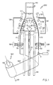
- FIG. 1 is a schematic diagram of a cross section of a system for producing continuous glass sheet according to one or more embodiments shown and described herein;
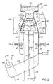
- FIG. 2 is a schematic diagram of a cross section of a system for producing continuous glass sheet according to one or more embodiments shown and described herein;
- FIG. 3 is a schematic diagram of one embodiment of a susceptor bearing for use in the systems for producing continuous glass sheets shown in FIGS. 1 and 2 ;
- FIG. 4 is a schematic diagram showing a tube of glass being drawn over the susceptor bearing of FIG. 3 ;
- FIG. 5 is an enlarged view of a portion of the susceptor bearing of FIG. 4 showing the spacing between the softened glass and the susceptor bearing;
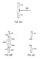
- FIGS. 6A-6C schematically depicted a process for sectioning a glass sheet from an expanded glass tube to produce a glass sheet having substantially defect-free edges.
- FIG. 1 One embodiment of a system for producing continuous glass sheet from a tube of glass is shown in FIG. 1 .
- the system generally comprises a substantially bell-shaped susceptor bearing, a heating system, a drawing system and a cutting device.
- Various embodiments of the system and methods for using the system to form continuous sheets of glass will be described in more detail herein.
- the systems 200, 300 are vertically oriented and may generally comprise a susceptor bearing 100, a heating system 118, a drawing mechanism 128, and a cutting device 140.
- the systems 200, 300 may additionally comprise a take-up mechanism 160 for winding continuous glass sheet on to a roll or storage spool.
- the system 300 shown in FIG. 2 may additionally comprise a glass delivery tank 150 for containing molten glass 152.
- the susceptor bearing 100 may be substantially bell-shaped and rotationally symmetric about a centerline C L .
- the susceptor bearing 100 may comprise a sidewall 110 that defines on internal chamber 116 (shown in FIGS. 1 and 2 ).
- the susceptor bearing 100 may comprise a top portion 102, an upper intermediate portion 104, a lower intermediate portion 106, and a bottom portion 108, as depicted in FIG. 3 .
- the top portion 102 and the bottom portion 108 may be substantially cylindrical with the bottom portion 108 having a diameter greater than the diameter of the top portion 102.
- the top portion 102 may have a diameter from about 28 mm to about 350 mm while the bottom portion 108 may have a diameter from about 60 mm to about 700 mm.
- the upper intermediate portion 104 may be substantially conical such that the diameter of the susceptor bearing 100 increases from the top portion 102 to the lower intermediate portion 106.
- the upper intermediate portion 104 may be shaped such that the surface of the sidewall 110 forms an angle from about 30° to about 45° with the centerline C L of the susceptor bearing 100.
- the lower intermediate portion 106 may be substantially spherical.
- substantially spherical means that the lower intermediate portion 106 of the susceptor bearing 100 has a uniform radius of curvature at the surface of the susceptor bearing which, if extended, would form a sphere. Accordingly, it will be understood that the lower intermediate portion 106 of the susceptor bearing 100 may have a geometrical configuration similar to a cross section of a sphere.
- the surface of the susceptor bearing 100 in the lower intermediate portion 106 may have a radius of curvature which forms a transition between the substantially conical shape of the upper intermediate portion 104 and the substantially cylindrical shape of the bottom portion 108.
- the upper intermediate portion 104 may comprise a first section 104A and a second section 104B.
- the surface of the sidewall 110 in the first section 104A may form a first angle ⁇ 1 with respect to the centerline C L while the surface of the sidewall 110 in the second section 104B may form a second angle ⁇ 2 with respect to the centerline C L , where ⁇ 1 ⁇ ⁇ 2 .
- the susceptor bearing 100 is described herein as being substantially bell-shaped and comprising a top portion 102, an upper intermediate portion 104, a lower intermediate portion 106, and a bottom portion 108, it should be understood that the susceptor bearing 100 may have other configurations.
- the susceptor bearing 100 may be substantially conical in shape or, alternatively, substantially parabolic in shape.
- the susceptor bearing may be of any configuration suitable for expanding and thinning a tube of heated glass drawn over the surface of the susceptor bearing, as will be described in more detail herein.
- the sidewall 110 of the susceptor bearing 100 may be porous such that a pressurized fluid introduced into the internal chamber 116 may be emitted from the susceptor bearing 100 through the sidewall 110.
- the material from which the susceptor bearing 100 is formed may have a porosity of greater than about 1%, more preferably greater than about 2% and, most preferably, from about 3% to about 6%.
- the material from which the susceptor bearing 100 is formed should be stable at elevated temperatures such that the susceptor bearing does not contaminate heated glass drawn over the susceptor bearing.
- the susceptor bearing 100 is formed from a porous carbon material, such as Ref 2020 produced by Carbon Lorraine of France.
- Ref. 2020 generally comprises an average carbon grain size from about 5 microns to about 20 microns and a porosity of about 4%.
- the sidewall 110 may have a radial thickness T from about 6 mm to about 12 mm.
- the radial thickness T of the sidewall 110 may be substantially uniform from the top portion 102 to the bottom portion 108.
- the radial thickness T of the sidewall 110 may be non-uniform.
- the radial thickness T of the sidewall 110 may vary up to about 30% of the maximum radial thickness T of the sidewall 110.
- the areas of the sidewall having a reduced radial thickness may be more permeable to a pressurized gas introduced into the internal chamber 116 and, therefore, may have a greater local flux of gas through the sidewall 110.
- a susceptor bearing 100 is described herein as comprising a porous carbon material, it should be understood that the susceptor bearing may be formed from other porous materials which are stable at high temperatures, such as ceramic materials.
- ceramic materials such as ceramic materials.
- cordierite ceramic or a similar ceramic material may be used to form the susceptor bearing 100.
- the susceptor bearing 100 may be sealably mounted on a support 114.
- the support 114 may comprise a fluid supply channel 112, such as a pipe, conduit or similar fluid delivery device, which is fluidly coupled to the internal chamber 116 of the susceptor bearing 100.
- the fluid supply channel 112 may be operable to deliver a supply of pressurized fluid to the internal chamber 116.
- the pressurized fluid may be a pressurized gas, specifically an inert pressurized gas, including, without limitation, nitrogen, helium, argon, krypton, xenon and the like.
- the susceptor bearing 100 and support 114 are fixed and the tubular glass preform 170 which is drawn over the susceptor bearing 100 is rotated relative to the susceptor bearing 100 as the tubular glass preform 170 is heated, expanded and thinned over the susceptor bearing.
- the susceptor bearing 100 may be operable to rotate relative to the glass delivery tank 150 such that the susceptor bearing 100 is rotated within the tube of glass drawn over the susceptor bearing 100.
- the susceptor bearing 100 and attached support 114 may be operable to rotate such as when the support 114 is mechanically coupled to the rotating armature of an electric motor.
- a heating system 118 may be disposed around the susceptor bearing 100.
- the heating system 118 may comprise an inductive heating system such as a 10 kW induction heating unit manufactured by Axio.
- inductive heating system such as a 10 kW induction heating unit manufactured by Axio.
- other types of heating systems including, without limitation, infrared, focused infrared, resistive and/or combination thereof
- FIGS. 1 and 2 depict the heating system as being disposed around the susceptor bearing 100, the heating system 118 may be integrated with the susceptor bearing 100, such as when the heating system 118 is a resistive heating system.
- the heating system 118 may be operable to create at least two distinct heating zones around the susceptor bearing 100.
- the heating system 118 comprises three separate induction coils: upper induction coil 120, intermediate induction coil 122, and lower induction coil 124.
- Each induction coil may be independently operated such that three separate heating zones are created around the susceptor bearing 100.
- upper induction coil 120 may be operated at a first temperature T 1 to heat the susceptor bearing 100 to a temperature at or just below the softening temperature of the glass drawn over the susceptor bearing.
- the intermediate induction coil 122 may be operated at a second temperature T 2 which is greater than T 1 and the third induction coil may be operated at a third temperature T 3 which is less than T 1 (e.g., a temperature less than the softening point of the glass).
- T 2 which is greater than T 1
- T 3 which is less than T 1 (e.g., a temperature less than the softening point of the glass).
- the heating system 118 may cooperate with the compressed fluid emitted from the surface of the susceptor bearing to control a temperature of the glass drawn over the susceptor bearing.
- the heating system 118 and the susceptor bearing 100 may be at least partially disposed in an enclosure 126 to shield the heated and softened glass 171 drawn over the susceptor bearing 100 from airborne contaminants such as, for example, dust and/or other particulate matter.
- the enclosure 126 may also provide thermal insulation to the susceptor bearing and heating system 118.
- the systems 200, 300 for forming glass sheet from tubes of glass may further comprise a drawing mechanism 128.
- the drawing mechanism 128 is generally disposed below the susceptor bearing 100 and may comprise at least one tractor wheel operable to contact the tube of glass drawn over the susceptor bearing 100 and draw the tube of glass downward.
- the drawing mechanism 128 may also assist in rotating the tube of glass. Accordingly, because the drawing mechanisms may impart both downward and rotational motion to the drawn tube of glass, it will be understood that an axis of rotation about which the at least one tractor wheel is rotated is non-parallel to the horizontal axis.
- the at least one tractor wheel may be positioned such that the angular orientation of the at least one tractor wheel is the same as the angle or pitch at which the tube of glass is sectioned.
- the drawing mechanism 128 comprises at least three pairs of opposed tractor wheels equidistantly spaced about the support 114.
- the tractor wheels may be disposed about the support 114 every 120°,
- Each pair of opposed tractor wheels may comprise an internal tractor wheel 130 and an external tractor wheel 132. At least one of the internal tractor wheel 130 and the external tractor wheel 132 may be coupled to a motor such that the wheel is driven.
- the internal tractor wheels 130 are mounted on the support 114 while the external tractor wheels 132 are mounted on an external support structure (not shown).
- the external tractor wheels 132 are spaced apart from the corresponding internal tractor wheels 130 such that an expanded glass tube 172 may be disposed between the internal tractor wheel 130 and the external tractor wheel 132.
- the internal tractor wheel 130 may contact the expanded glass tube 172 on the internal surface of the tube (e.g., along the inner diameter or ID of the expanded glass tube 172) while the external tractor wheel 132 may contact the expanded glass tube 172 on the external surface of the expanded glass tube (e.g., along the outer diameter or OD of the expanded glass tube 172).
- the drawing mechanism 128 may be disposed a sufficient distance below the susceptor bearing 100 such that the expanded glass tube 172 is air cooled to a temperature above the strain point of the glass before being contacted by the tractor wheels of the drawing mechanism 128.
- the drawing mechanism 128 may be positioned below the susceptor bearing 100 such that the expanded glass tube 172 is air cooled to at least 650° C before the expanded glass tube 172 is contacted by the drawing mechanism 128.
- the systems 200, 300 for forming glass sheet from a tube of glass may further comprise a cutting device 140 which is operable to section an expanded glass tube 172 into a continuous glass sheet 400 or continuous ribbon.
- the cutting device 140 may comprise a laser, such as a CO 2 laser, a quadrupled 266 nm YAG laser, or excimer laser (193/248/308 nm), a mechanical cutting device such as blades, shears, or diamond scorer, or a device which sections the expanded glass tube 172 based on the propagation of thermal stresses in the material.
- the width of the continuous glass sheet 400 may be controlled by varying the speed at which a tube of glass is fed on to the susceptor bearing, the speed at which the tube of glass is drawn over the susceptor bearing, the relative speed of rotation of the susceptor bearing and the tube of glass, and the pitch at which the expanded glass tube 172 is cut.
- the cutting device 140 is a CO 2 laser which is positioned below the drawing mechanism 128.
- the cutting device may be positioned below the drawing mechanism 128 a suitable distance such that the tube of glass is sectioned with the CO 2 laser while the tube of glass is at a temperature above the strain point of the glass. Sectioning the glass at a temperature above the strain point of the glass mitigates the development of residual stresses in the sectioned continuous glass sheet 400.
- the cutting device 140 is a CO 2 laser positioned to section the expanded glass tube 172 when the glass is at a temperature below the strain point of the glass.
- the CO 2 laser may be used to section the glass such that the resultant glass sheet has defect-free edges.
- the CO 2 laser may be a 10.6 micron wavelength Synrad rf-excited CO 2 laser with a maximum power of 80W and beam diameter of 7.2 mm.
- the beam of the CO 2 laser may be focused on to the surface of the glass to be sectioned with a 2.5 inch focusing lens to produce a spot size on the glass of 131 microns.
- the beam 306 of the CO 2 laser may be directed on to the expanded glass tube 172 (as shown in FIG. 6A in partial cross section) with sufficient power to cause a separation 350 in the glass by fusion and the formation of a thermally affected zone (TAZ) 302 on either side of the separation 350.
- TAZ thermally affected zone
- the power of the CO 2 laser may be from about 60 W to about 80 W.
- the TAZ 302 (shown in FIG. 6B ) may generally be about 1mm in width.
- the high thermal stresses induced in the glass by the CO 2 laser may cause cracks 310 to develop and propagate in the glass directly adjacent to the TAZ 302 and parallel to the cutting path of the CO 2 laser.
- the cracks cause the TAZ 302 to separate from the remainder of the glass (e.g., from the expanded glass tube 172 and sectioned glass sheet 400), as shown in FIG. 6C , leaving defect free edges 308 on each of the expanded glass tube 172 and the sectioned continuous glass sheet 400.
- This sectioning technique may be used to section glass having a thickness from about 20 microns to about 150 microns for cutting speeds of about 25 mm/sec to about 45 mm/sec with thinner glass requiring faster cutting speeds for a given laser power.
- a cutting speed of about 25 mm/sec to about 30 mm/sec with a laser power of about 80 W may be used to produce substantially defect-free edges in the sectioned glass.
- a cutting speed from about 35 mm/sec to about 40 mm/sec with a laser power of about 80 W may be used to produce substantially defect-free edges while borosilicate glass having a thickness of 70 microns may be sectioned with cutting speeds from about 40 mm/sec to about 45 mm/sec with a laser power of about 80 W to produce substantially defect-free edges.
- the cutting device 140 may be positioned to section the expanded glass tube 172 along the line where the tractor wheels of the drawing mechanism 128 make contact with the expanded glass tube 172 such that any defects which may be introduced into the glass by contact with the tractor wheels of the drawing mechanism are located in cutting path of the laser and therefore eliminated as the glass is sectioned.
- the cutting device 140 may be positioned at an angle or pitch relative to the glass such that the glass is helicoidally or spirally sectioned from the expanded glass tube 172.
- the pitch may be set by adjusting the angular orientation of the cutting device with respect to the expanded glass tube.
- the pitch of the cutting device in conjunction with the draw speed of the drawing mechanism, determines the width of the resulting continuous glass sheet 400.
- the systems 200, 300 for forming glass sheets from a tube of glass may further comprise a take-up mechanism 160
- the take-up mechanism 160 may generally comprise a rotating spool or roll 162 on to which the sectioned continuous glass sheet 400 may be wound.
- the axis of rotation 161 of the take-up mechanism 160 may be generally perpendicular to the pitch on which the expanded glass tube 172 is sectioned such that the sectioned continuous glass sheet 400 may be uniformly wound on to the spool or roll.
- the speed of rotation of the take-up mechanism 160 may be varied to coincide with the rate at which the tube of glass is drawn over the susceptor bearing 100 and sectioned into the continuous glass sheet 400.
- the tube of glass is a rigid, tubular glass preform 170 which may be positioned over the top portion 102 of the susceptor bearing 100 as shown in FIG. 1 .
- the tubular glass preform 170 may generally comprise a hollow glass cylinder with an inner diameter which is slightly larger than the diameter of the top portion of the susceptor bearing 100.
- the tube of glass may have a wall thickness on the order of several millimeters. For example, in one embodiment, the tube of glass may be 2 mm thick.
- the tube of glass may have a wall thickness of greater than 2 mm or less than 2 mm.
- the tubular glass preform is shown and described herein as being a cylinder or cylindrical, it should be understood that the tubular glass preform may have various other geometrical configurations.
- the tubular glass preform 170 may be elliptical or oval in cross section or a similar elongated cross section.
- the tubular glass preform 170 may comprise borosilicate glass such as, for example, 7761 Pyrex® or similar Pyrex® glass compositions, JadeTM, or Eagle 2000TM.
- the tubular glass preform 170 may be rotated relative to the susceptor bearing 100 at a rate from about 2 rpm to about 10 rpm as the tubular glass preform 170 is fed on to the susceptor bearing 100 by gravity.
- the heating system 118 may be used to heat the tubular glass preform 170 to a temperature above the softening point of the glass.
- the upper induction coil 120 may be operated to pre-heat the tube of glass to a temperature just below the softening point of the glass.
- the tubular glass preform 170 comprises 7761 Pyrex®
- the induction coil 120 may be used to heat the tubular glass preform 170 to a first temperature T1 of 650° C.
- the tube of glass drawn over the susceptor bearing 100 is a solid tubular glass preform 170
- the tube of glass may initially be a tube of molten glass.
- the top portion of the susceptor bearing 100 may be coupled to a glass delivery tank 150 which contains molten glass 152.
- the molten glass may be a borosilicate glass composition such as, for example, 7761 Pyrex® or similar Pyrex® glass compositions, JadeTM, or Eagle 2000TM.
- the top portion of the susceptor bearing 100 forms the molten glass into a hollow tube having an inner diameter of the same dimension as the diameter of the top portion of the susceptor bearing 100.
- the susceptor bearing 100 may be rotated from about 2 rpm to about 10 rpm as the glass flows over the susceptor bearing 100.
- the heating system 118 may be used to maintain the temperature of the tube of glass above the softening point of the glass.
- the upper induction coil 120 may be used to maintain the glass at a first temperature T1 above the softening point of the glass as the glass is fed downward, over the susceptor bearing 100.
- the initial feed of glass is gravity fed or drawn or pulled downward over the susceptor bearing 100 until the glass can be placed in contact with the tractor wheels of the drawing mechanism 128. Thereafter, a combination of gravity feeding and drawing with the drawing mechanism 128 are used to maintain a continuous draw of glass over the susceptor bearing 100.
- the glass may be further heated by the intermediate induction coil 122 to a second temperature T 2 above the softening point of the glass to increase the plastic flow of the glass.
- T 2 may be about 885° C.
- the diameter of the softened glass 171 is both expanded (e.g., the circumference of the softened glass 171 is increased) and thinned (e.g., the thickness of the softened glass 171 is decreased) as the softened glass 171 is drawn over the upper intermediate portion 104 of the susceptor bearing 100.
- the softened glass 171 is drawn over the susceptor bearing 100, particularly as the softened glass 171 is drawn over the upper intermediate portion 104, the lower intermediate portion 106 and the bottom portion 108 of the susceptor bearing 100, the softened glass 171 is supported or suspended over the surface of the susceptor bearing 100 such that there is no mechanical contact between the susceptor bearing 100 and the softened glass 171.
- This is accomplished by supplying a compressed fluid such as, for example, compressed nitrogen gas, to the internal chamber 116 of the susceptor bearing 100 via the fluid supply channel 112.
- the pressure of the fluid in the inner chamber may be from about 0.5 to about 3 bars such that a flux of the pressurized fluid is emitted through the porous sidewall of the susceptor bearing 100.
- the flux of fluid through the porous sidewall blows the softened glass 171 outwards, away from the surface of the susceptor bearing 100 in a radial direction thereby further expanding and thinning the softened glass 171 while preventing the softened glass 171 from contacting the surface of the susceptor bearing 100. For example, as shown in FIG.
- the softened glass 171 may be supported above the surface of the sidewall 110 of the susceptor bearing 100 by the fluid flux by a distance S of less than about 200 microns, preferably less than about 150 microns, more preferably less than about 120 microns.
- expansion and thinning of the softened glass 171 primarily takes place over the upper intermediate portion 104 of the susceptor bearing 100 due to the shape of the susceptor bearing.
- the amount of radial expansion that takes place in the softened glass 171 may be related to the shape and dimensions of the susceptor bearing 100 as well as the amount of fluid flux through the sidewall 110 of the susceptor bearing 100 (e.g., the greater the fluid flux, the further the softened glass 171 is blow or suspended over the susceptor bearing 100).
- the amount of thinning or reduction in thickness of the softened glass 171 may be dependent on the shape and dimensions of the susceptor bearing 100, the flux of fluid through the sidewall 110 of the susceptor bearing 100, the rate at which glass is fed on to the susceptor bearing 100, and the rate at which the glass is drawn over the susceptor bearing 100 by the drawing mechanism 128. Generally, the faster the softened glass is drawn, the thinner the softened glass becomes.
- the lower intermediate portion 106 transitions the softened glass to the bottom portion 108 of the susceptor bearing 100 where the softened glass 171 is calibrated to its final dimensions.
- the temperature of the glass is rapidly decreased below the softening point of the glass in order to solidify the glass such that the glass maintains its cylindrical shape and thickness.
- the lower induction coil 124 may be set to heat the glass to a temperature of 810° C such that the glass can be rapidly air cooled to "freeze" in the desired dimensions.
- the tube of glass (now expanded glass tube 172) is contacted by the drawing mechanism 128 which exerts both a downward draw force and circumferential or rotational force on the expanded glass tube 172.
- the tractor wheels 130,132 of the drawing mechanism 128 may contact the expanded glass tube 172 while the glass is above the strain point of the glass.
- the drawing mechanism 128 contacts the expanded glass tube 172 when the glass has a temperature of about 600° C.
- the expanded glass tube 172 may be sectioned into a continuous glass sheet 400, as described hereinabove. More specifically, the expanded glass tube 172 is sectioned along the path of travel of the tractor wheels thereby eliminating any defects caused by the mechanical contact of the tractor wheels with the glass. In the embodiments shown and described herein, the tube is helicoidally or spirally sectioned to form the expanded glass tube into a continuous glass sheet. Thereafter, the continuous glass sheet 400 may be wound on to a storage spool or roll with the take-up mechanism 160.
- the systems and methods described herein may be utilized to form continuous glass sheets from a tube of glass. More specifically, the methods and systems described herein may be utilized to form continuous glass sheets having a thickness of less than about 150 microns, more preferably less than about 100 microns and, most preferably, less than about 50 microns. Because mechanical contact with the glass is minimized during formation of the glass sheets, the continuous glass sheets formed utilizing the systems and methods describe herein may have a low surface roughness. For example, the continuous glass sheets may have a surface roughness of less than about 2 nm Ra, more preferably less than about I nm Ra and, most preferably, less than about 0.6 nm Ra.
- a susceptor bearing having a maximum outer diameter (e.g., the diameter of the bottom portion) of about 700 mm may be used to produce continuous glass sheets having a width of up to about 2.1 meters.
- the same susceptor bearing may also be utilized to form narrow ribbons of glass by adjusting the pitch of the cutting device and/or the feed and draw rates of the glass over the susceptor bearing.
- the tubular glass preform was rotated at a rate of 4 rpm with respect to the susceptor bearing 100.
- the tubular glass preform was heated to a first temperature T1 of 650° C around the top portion of the susceptor bearing, to a second temperature T2 of 885° C around the upper intermediate portion of the susceptor bearing, and to a third temperature T3 of 810° C around the bottom portion of the susceptor bearing as the preform was drawn over the susceptor bearing at a rate of 100 mm/min.
- the softened glass of the tubular glass preform was blown and suspended over the susceptor bearing by a distance of about 120 microns by providing a pressurized flow of nitrogen gas to the internal chamber of the susceptor bearing at a pressure of about 0.8 bar, which, in turn, was emitted through the sidewall of the susceptor bearing.
- the expanded glass tube After being drawn over the susceptor bearing the expanded glass tube was cooled to below the softening temperature.
- the final circumference of the tubular glass preform was increased from about 60 mm to about 102 mm while the thickness of the tubular glass preform was reduced from 2 mm to about 50 microns.
- the glass was sectioned and surface roughness measurements were performed on the sectioned glass with a Zygo surface metrology instrument.
- the sectioned glass had a surface roughness of less than about 0.6 nm Ra which is attributable to the non-contact methods of forming the glass from the tubular glass preform.
- One advantage of the methods and systems described herein is the ability to form a continuous glass sheet from a cylindrical feed of glass which is flexible enough to be rolled on to a storage spool. Because the glass sheet is continuous, the glass may be utilized to form large or small individual sheets of glass from a single spool of glass. Moreover, the rolled continuous glass sheet may facilitate incorporating the material into a large scale commercial production operation where the glass may be accurately paid out from a single source and cut to size thereby reducing the handling required with a plurality of individually formed glass sheets.
- the methods and systems described herein are also environmentally friendly.
- the systems described herein are relatively compact systems where only the interior of the system is heated with very limited heating losses to the outside environment. Further, the amount of nitrogen consumed or released by the process is also relatively low. Finally, the power consumed in heating the glass is relatively low in comparison to other glass forming operations.
Landscapes
- Chemical & Material Sciences (AREA)
- Engineering & Computer Science (AREA)
- Materials Engineering (AREA)
- Organic Chemistry (AREA)
- Physics & Mathematics (AREA)
- Health & Medical Sciences (AREA)
- Optics & Photonics (AREA)
- Toxicology (AREA)
- Thermal Sciences (AREA)
- Re-Forming, After-Treatment, Cutting And Transporting Of Glass Products (AREA)
- Manufacturing Of Magnetic Record Carriers (AREA)
- Electroluminescent Light Sources (AREA)
Abstract
Description
- The embodiments described herein generally relate to methods and systems for forming glass sheets, and, more particularly, to methods and apparatus for forming thin, continuous glass sheets.
- Organic light emitting diodes (OLEDs) have been the subject of a considerable amount of research in recent years because of their potential for use in a wide variety of electroluminescent devices. For instance, a single OLED can be used as a discrete light emitting device or an array of OLEDs can be used in lighting applications or flat-panel applications such as flexible displays. However, OLED displays and, in particular, the electrodes and organic layers of individual OLEDs, may be susceptible to degradation resulting from interaction with oxygen and moisture. Polymeric materials used as substrates in flexible OLED displays may be permeable to oxygen and moisture and, therefore, are not effective for sealing displays and preventing the degradation of the OLED devices. Metal foils offer a suitable alternative to polymeric materials as some metal foils may be impermeable to both oxygen and moisture. However, the optical properties of the metal foils, specifically the transparency or lack of transparency of the metal foils, make the foils unsuitable for use in conjunction with OLED display devices.
- Glass may be a suitable alternative to both polymeric materials and metal foils for use in conjunction with OLED displays. Glass provides the desired optical transparency while being impermeable to moisture and oxygen. As such, glass may be suitable to form a hermetic seal around OLEDs in a display. However, glass is not generally a flexible material, except when the glass is ultra-thin and existing methods for producing ultra-thin glass are not suitable for large volume, commercial production.
- Accordingly, a need exists for alternative methods and systems for producing thin, continuous sheets of glass.
- According to one embodiment shown and described herein, a method for forming a continuous glass sheet includes expanding and thinning a tube of glass by drawing the tube of glass over a susceptor bearing comprising a porous sidewall defining an internal chamber. A diameter of the susceptor bearing may increase between a top portion of the susceptor bearing and a bottom portion of the susceptor bearing. The tube of glass may be maintained at a temperature above a softening point of the glass as the tube of glass is drawn over the susceptor bearing. The tube of glass may be suspended over the susceptor bearing by blowing the tube of glass away from the susceptor bearing in a radial direction with a pressurized fluid supplied to the internal chamber and emitted from the porous sidewall as the tube of glass is drawn over the susceptor bearing. Thereafter, the tube of glass may be cooled and sectioned to form a continuous glass sheet.
- In another embodiment, a system for forming a continuous glass sheet includes a susceptor bearing, a heating system surrounding the susceptor bearing, a drawing mechanism and a cutting device. The susceptor bearing may include a porous sidewall defining an internal chamber for receiving a pressurized fluid. A diameter of the susceptor bearing may increase between a top portion of the susceptor bearing and a bottom portion of the susceptor bearing. The susceptor bearing may be operable to emit the pressurized fluid through the porous sidewall such that, when a heated tube of glass is drawn over the susceptor bearing, the heated tube of glass is blown away from the susceptor bearing in a radial direction thereby suspending the tube of glass over the susceptor bearing. The heating system may cooperate with the pressurized fluid emitted from the susceptor bearing to regulate a temperature of a tube of glass drawn over the susceptor bearing. The drawing mechanism is disposed below the susceptor bearing and includes at least one tractor wheel positioned to contact the tube of glass and draw the tube of glass over the susceptor bearing in a downward direction. The cutting device may be positioned below the drawing mechanism and may be operable to section the tube of glass into a continuous glass sheet.
- Additional features and advantages of the embodiments described herein will be set forth in the detailed description which follows, and in part will be readily apparent to those skilled in the art from that description or recognized by practicing the invention as described herein, including the detailed description which follows, the claims, as well as the appended drawings.
- It is to be understood that both the foregoing general description and the following detailed description are intended to provide an overview or framework for understanding the nature and character of the claims. The accompanying drawings are included to provide a further understanding of the embodiments described herein, and are incorporated into and constitute a part of this specification. The drawings illustrate various embodiments described herein and, in conjunction with the description, serve to explain the principles and operations of the described embodiments.
-
FIG. 1 is a schematic diagram of a cross section of a system for producing continuous glass sheet according to one or more embodiments shown and described herein; -
FIG. 2 is a schematic diagram of a cross section of a system for producing continuous glass sheet according to one or more embodiments shown and described herein; -
FIG. 3 is a schematic diagram of one embodiment of a susceptor bearing for use in the systems for producing continuous glass sheets shown inFIGS. 1 and2 ; -
FIG. 4 is a schematic diagram showing a tube of glass being drawn over the susceptor bearing ofFIG. 3 ; -
FIG. 5 is an enlarged view of a portion of the susceptor bearing ofFIG. 4 showing the spacing between the softened glass and the susceptor bearing; and -
FIGS. 6A-6C schematically depicted a process for sectioning a glass sheet from an expanded glass tube to produce a glass sheet having substantially defect-free edges. - Reference will now be made in detail to various methods and apparatus for forming continuous glass sheets described herein, examples of which are illustrated in the accompanying drawings. Whenever possible, the same reference numerals will be used throughout the drawings to refer to the same or like parts. One embodiment of a system for producing continuous glass sheet from a tube of glass is shown in
FIG. 1 . The system generally comprises a substantially bell-shaped susceptor bearing, a heating system, a drawing system and a cutting device. Various embodiments of the system and methods for using the system to form continuous sheets of glass will be described in more detail herein. - Referring now to
FIGS. 1 and2 , two embodiments ofsystems systems heating system 118, adrawing mechanism 128, and acutting device 140. Thesystems up mechanism 160 for winding continuous glass sheet on to a roll or storage spool. Thesystem 300 shown inFIG. 2 may additionally comprise aglass delivery tank 150 for containingmolten glass 152. - Referring now to
FIGS. 1-3 , the susceptor bearing 100 may be substantially bell-shaped and rotationally symmetric about a centerline CL. The susceptor bearing 100 may comprise asidewall 110 that defines on internal chamber 116 (shown inFIGS. 1 and2 ). In one embodiment, the susceptor bearing 100 may comprise atop portion 102, an upperintermediate portion 104, a lowerintermediate portion 106, and abottom portion 108, as depicted inFIG. 3 . Thetop portion 102 and thebottom portion 108 may be substantially cylindrical with thebottom portion 108 having a diameter greater than the diameter of thetop portion 102. For example, thetop portion 102 may have a diameter from about 28 mm to about 350 mm while thebottom portion 108 may have a diameter from about 60 mm to about 700 mm. - The upper
intermediate portion 104 may be substantially conical such that the diameter of the susceptor bearing 100 increases from thetop portion 102 to the lowerintermediate portion 106. For example, in one embodiment, the upperintermediate portion 104 may be shaped such that the surface of thesidewall 110 forms an angle from about 30° to about 45° with the centerline CL of the susceptor bearing 100. - The lower
intermediate portion 106 may be substantially spherical. The term substantially spherical, as used herein, means that the lowerintermediate portion 106 of the susceptor bearing 100 has a uniform radius of curvature at the surface of the susceptor bearing which, if extended, would form a sphere. Accordingly, it will be understood that the lowerintermediate portion 106 of the susceptor bearing 100 may have a geometrical configuration similar to a cross section of a sphere. For example, the surface of the susceptor bearing 100 in the lowerintermediate portion 106 may have a radius of curvature which forms a transition between the substantially conical shape of the upperintermediate portion 104 and the substantially cylindrical shape of thebottom portion 108. - In one embodiment, the upper
intermediate portion 104 may comprise afirst section 104A and asecond section 104B. The surface of thesidewall 110 in thefirst section 104A may form a first angle θ1 with respect to the centerline CL while the surface of thesidewall 110 in thesecond section 104B may form a second angle θ2 with respect to the centerline CL, where θ1 < θ2. - While the susceptor bearing 100 is described herein as being substantially bell-shaped and comprising a
top portion 102, an upperintermediate portion 104, a lowerintermediate portion 106, and abottom portion 108, it should be understood that the susceptor bearing 100 may have other configurations. For example, the susceptor bearing 100 may be substantially conical in shape or, alternatively, substantially parabolic in shape. Accordingly, it will be understood that the susceptor bearing may be of any configuration suitable for expanding and thinning a tube of heated glass drawn over the surface of the susceptor bearing, as will be described in more detail herein. - Still referring to
FIGS. 1-3 , thesidewall 110 of the susceptor bearing 100 may be porous such that a pressurized fluid introduced into theinternal chamber 116 may be emitted from the susceptor bearing 100 through thesidewall 110. For example, the material from which thesusceptor bearing 100 is formed may have a porosity of greater than about 1%, more preferably greater than about 2% and, most preferably, from about 3% to about 6%. The material from which thesusceptor bearing 100 is formed should be stable at elevated temperatures such that the susceptor bearing does not contaminate heated glass drawn over the susceptor bearing. - In one embodiment, the
susceptor bearing 100 is formed from a porous carbon material, such as Ref 2020 produced by Carbon Lorraine of France. Ref. 2020 generally comprises an average carbon grain size from about 5 microns to about 20 microns and a porosity of about 4%. When thesusceptor bearing 100 is formed from carbon, thesidewall 110 may have a radial thickness T from about 6 mm to about 12 mm. In one embodiment, the radial thickness T of thesidewall 110 may be substantially uniform from thetop portion 102 to thebottom portion 108. Alternatively, the radial thickness T of thesidewall 110 may be non-uniform. For example, when the radial thickness T of thesidewall 110 is non-uniform, the radial thickness may vary up to about 30% of the maximum radial thickness T of thesidewall 110. In this embodiment, the areas of the sidewall having a reduced radial thickness may be more permeable to a pressurized gas introduced into theinternal chamber 116 and, therefore, may have a greater local flux of gas through thesidewall 110. - While one example of a
susceptor bearing 100 is described herein as comprising a porous carbon material, it should be understood that the susceptor bearing may be formed from other porous materials which are stable at high temperatures, such as ceramic materials. For example, in one embodiment cordierite ceramic or a similar ceramic material may be used to form thesusceptor bearing 100. - Referring again to
FIGS. 1 and2 , thesusceptor bearing 100 may be sealably mounted on asupport 114. Thesupport 114 may comprise afluid supply channel 112, such as a pipe, conduit or similar fluid delivery device, which is fluidly coupled to theinternal chamber 116 of thesusceptor bearing 100. Thefluid supply channel 112 may be operable to deliver a supply of pressurized fluid to theinternal chamber 116. In the embodiments described herein, the pressurized fluid may be a pressurized gas, specifically an inert pressurized gas, including, without limitation, nitrogen, helium, argon, krypton, xenon and the like. - In the embodiment of the
system 200 shown inFIG. 1 , thesusceptor bearing 100 andsupport 114 are fixed and thetubular glass preform 170 which is drawn over thesusceptor bearing 100 is rotated relative to the susceptor bearing 100 as thetubular glass preform 170 is heated, expanded and thinned over the susceptor bearing. - However, in the embodiment of the
system 300 shown inFIG. 2 , where thesystem 300 comprises aglass delivery tank 150 for supplying a tube of molten glass to thesusceptor bearing 100, thesusceptor bearing 100 may be operable to rotate relative to theglass delivery tank 150 such that thesusceptor bearing 100 is rotated within the tube of glass drawn over thesusceptor bearing 100. For example, in this embodiment, thesusceptor bearing 100 and attachedsupport 114 may be operable to rotate such as when thesupport 114 is mechanically coupled to the rotating armature of an electric motor. - Referring again to
FIGS. 1 and2 , aheating system 118 may be disposed around thesusceptor bearing 100. In one embodiment, theheating system 118 may comprise an inductive heating system such as a 10 kW induction heating unit manufactured by Axio. However, it should be understood that other types of heating systems may be used including, without limitation, infrared, focused infrared, resistive and/or combination thereof Further, it should be understood that, whileFIGS. 1 and2 depict the heating system as being disposed around thesusceptor bearing 100, theheating system 118 may be integrated with thesusceptor bearing 100, such as when theheating system 118 is a resistive heating system. - The
heating system 118 may be operable to create at least two distinct heating zones around thesusceptor bearing 100. For example, in the embodiment shown inFIGS. 1 and2 , theheating system 118 comprises three separate induction coils:upper induction coil 120,intermediate induction coil 122, andlower induction coil 124. Each induction coil may be independently operated such that three separate heating zones are created around thesusceptor bearing 100. For example,upper induction coil 120 may be operated at a first temperature T1 to heat the susceptor bearing 100 to a temperature at or just below the softening temperature of the glass drawn over the susceptor bearing. Theintermediate induction coil 122 may be operated at a second temperature T2 which is greater than T1 and the third induction coil may be operated at a third temperature T3 which is less than T1 (e.g., a temperature less than the softening point of the glass). The temperatures at which each of the induction coils are heated will be described in more detail herein with reference to specific compositions of glass drawn over thesusceptor bearing 100. - Further, it should be understood that the
heating system 118 may cooperate with the compressed fluid emitted from the surface of the susceptor bearing to control a temperature of the glass drawn over the susceptor bearing. - The
heating system 118 and thesusceptor bearing 100 may be at least partially disposed in anenclosure 126 to shield the heated andsoftened glass 171 drawn over the susceptor bearing 100 from airborne contaminants such as, for example, dust and/or other particulate matter. Theenclosure 126 may also provide thermal insulation to the susceptor bearing andheating system 118. - Still referring to
FIGS. 1 and2 , thesystems drawing mechanism 128. Thedrawing mechanism 128 is generally disposed below thesusceptor bearing 100 and may comprise at least one tractor wheel operable to contact the tube of glass drawn over thesusceptor bearing 100 and draw the tube of glass downward. Thedrawing mechanism 128 may also assist in rotating the tube of glass. Accordingly, because the drawing mechanisms may impart both downward and rotational motion to the drawn tube of glass, it will be understood that an axis of rotation about which the at least one tractor wheel is rotated is non-parallel to the horizontal axis. Specifically, the at least one tractor wheel may be positioned such that the angular orientation of the at least one tractor wheel is the same as the angle or pitch at which the tube of glass is sectioned. - In the embodiments of the
systems FIGS. 1 and2 , thedrawing mechanism 128 comprises at least three pairs of opposed tractor wheels equidistantly spaced about thesupport 114. For example, when thedrawing mechanism 128 comprises three pairs of opposed tractor wheels, the tractor wheels may be disposed about thesupport 114 every 120°, - Each pair of opposed tractor wheels may comprise an
internal tractor wheel 130 and anexternal tractor wheel 132. At least one of theinternal tractor wheel 130 and theexternal tractor wheel 132 may be coupled to a motor such that the wheel is driven. Theinternal tractor wheels 130 are mounted on thesupport 114 while theexternal tractor wheels 132 are mounted on an external support structure (not shown). Theexternal tractor wheels 132 are spaced apart from the correspondinginternal tractor wheels 130 such that an expandedglass tube 172 may be disposed between theinternal tractor wheel 130 and theexternal tractor wheel 132. Accordingly, theinternal tractor wheel 130 may contact the expandedglass tube 172 on the internal surface of the tube (e.g., along the inner diameter or ID of the expanded glass tube 172) while theexternal tractor wheel 132 may contact the expandedglass tube 172 on the external surface of the expanded glass tube (e.g., along the outer diameter or OD of the expanded glass tube 172). - In the embodiments described herein, the
drawing mechanism 128 may be disposed a sufficient distance below the susceptor bearing 100 such that the expandedglass tube 172 is air cooled to a temperature above the strain point of the glass before being contacted by the tractor wheels of thedrawing mechanism 128. For example, for a tube of borosilicate glass such as Pyrex® 7761 (strain point = 458° C) heated and drawn over thesusceptor bearing 100, thedrawing mechanism 128 may be positioned below the susceptor bearing 100 such that the expandedglass tube 172 is air cooled to at least 650° C before the expandedglass tube 172 is contacted by thedrawing mechanism 128. - Still referring to
FIGS. 1 and2 , thesystems cutting device 140 which is operable to section an expandedglass tube 172 into acontinuous glass sheet 400 or continuous ribbon. Thecutting device 140 may comprise a laser, such as a CO2 laser, a quadrupled 266 nm YAG laser, or excimer laser (193/248/308 nm), a mechanical cutting device such as blades, shears, or diamond scorer, or a device which sections the expandedglass tube 172 based on the propagation of thermal stresses in the material. The width of thecontinuous glass sheet 400 may be controlled by varying the speed at which a tube of glass is fed on to the susceptor bearing, the speed at which the tube of glass is drawn over the susceptor bearing, the relative speed of rotation of the susceptor bearing and the tube of glass, and the pitch at which the expandedglass tube 172 is cut. - In one embodiment, the
cutting device 140 is a CO2 laser which is positioned below thedrawing mechanism 128. Specifically, the cutting device may be positioned below the drawing mechanism 128 a suitable distance such that the tube of glass is sectioned with the CO2 laser while the tube of glass is at a temperature above the strain point of the glass. Sectioning the glass at a temperature above the strain point of the glass mitigates the development of residual stresses in the sectionedcontinuous glass sheet 400. - Referring to
FIGS. 6A -6C , in another embodiment, thecutting device 140 is a CO2 laser positioned to section the expandedglass tube 172 when the glass is at a temperature below the strain point of the glass. The CO2 laser may be used to section the glass such that the resultant glass sheet has defect-free edges. In this embodiment, the CO2 laser may be a 10.6 micron wavelength Synrad rf-excited CO2 laser with a maximum power of 80W and beam diameter of 7.2 mm. The beam of the CO2 laser may be focused on to the surface of the glass to be sectioned with a 2.5 inch focusing lens to produce a spot size on the glass of 131 microns. - Referring now to
FIGS. 6A-6C , in order to section the glass, thebeam 306 of the CO2 laser may be directed on to the expanded glass tube 172 (as shown inFIG. 6A in partial cross section) with sufficient power to cause aseparation 350 in the glass by fusion and the formation of a thermally affected zone (TAZ) 302 on either side of theseparation 350. In order to section borosilicate glass having a thickness of up to about 150 microns, the power of the CO2 laser may be from about 60 W to about 80 W. The TAZ 302 (shown inFIG. 6B ) may generally be about 1mm in width. The high thermal stresses induced in the glass by the CO2 laser may causecracks 310 to develop and propagate in the glass directly adjacent to theTAZ 302 and parallel to the cutting path of the CO2 laser. The cracks cause theTAZ 302 to separate from the remainder of the glass (e.g., from the expandedglass tube 172 and sectioned glass sheet 400), as shown inFIG. 6C , leaving defectfree edges 308 on each of the expandedglass tube 172 and the sectionedcontinuous glass sheet 400. - This sectioning technique may be used to section glass having a thickness from about 20 microns to about 150 microns for cutting speeds of about 25 mm/sec to about 45 mm/sec with thinner glass requiring faster cutting speeds for a given laser power. For example, for a borosilicate glass having a thickness of 120 microns, a cutting speed of about 25 mm/sec to about 30 mm/sec with a laser power of about 80 W may be used to produce substantially defect-free edges in the sectioned glass. Similarly, for a borosilicate glass having a thickness of 100 microns, a cutting speed from about 35 mm/sec to about 40 mm/sec with a laser power of about 80 W may be used to produce substantially defect-free edges while borosilicate glass having a thickness of 70 microns may be sectioned with cutting speeds from about 40 mm/sec to about 45 mm/sec with a laser power of about 80 W to produce substantially defect-free edges.
- Regardless of the technique used to section the glass, the
cutting device 140 may be positioned to section the expandedglass tube 172 along the line where the tractor wheels of thedrawing mechanism 128 make contact with the expandedglass tube 172 such that any defects which may be introduced into the glass by contact with the tractor wheels of the drawing mechanism are located in cutting path of the laser and therefore eliminated as the glass is sectioned. - Further, it should be understood that the
cutting device 140 may be positioned at an angle or pitch relative to the glass such that the glass is helicoidally or spirally sectioned from the expandedglass tube 172. The pitch may be set by adjusting the angular orientation of the cutting device with respect to the expanded glass tube. The pitch of the cutting device, in conjunction with the draw speed of the drawing mechanism, determines the width of the resultingcontinuous glass sheet 400. - Referring again to
FIGS. 1 and2 , thesystems mechanism 160, The take-upmechanism 160 may generally comprise a rotating spool or roll 162 on to which the sectionedcontinuous glass sheet 400 may be wound. The axis ofrotation 161 of the take-upmechanism 160 may be generally perpendicular to the pitch on which the expandedglass tube 172 is sectioned such that the sectionedcontinuous glass sheet 400 may be uniformly wound on to the spool or roll. Further, the speed of rotation of the take-upmechanism 160 may be varied to coincide with the rate at which the tube of glass is drawn over thesusceptor bearing 100 and sectioned into thecontinuous glass sheet 400. - Reference will now be made to
FIGS. 1 and2 to illustrate the functionality of thesystems tubular glass preform 170 which may be positioned over thetop portion 102 of the susceptor bearing 100 as shown inFIG. 1 . As depicted herein, thetubular glass preform 170 may generally comprise a hollow glass cylinder with an inner diameter which is slightly larger than the diameter of the top portion of thesusceptor bearing 100. The tube of glass may have a wall thickness on the order of several millimeters. For example, in one embodiment, the tube of glass may be 2 mm thick. However, it should be understood that the tube of glass may have a wall thickness of greater than 2 mm or less than 2 mm. Further, while the tubular glass preform is shown and described herein as being a cylinder or cylindrical, it should be understood that the tubular glass preform may have various other geometrical configurations. For example, in one embodiment, thetubular glass preform 170 may be elliptical or oval in cross section or a similar elongated cross section. - The
tubular glass preform 170 may comprise borosilicate glass such as, for example, 7761 Pyrex® or similar Pyrex® glass compositions, Jade™, or Eagle 2000™. In one embodiment, thetubular glass preform 170 may be rotated relative to the susceptor bearing 100 at a rate from about 2 rpm to about 10 rpm as thetubular glass preform 170 is fed on to the susceptor bearing 100 by gravity. - As the
tubular glass preform 170 is fed on to thesusceptor bearing 100, theheating system 118 may be used to heat thetubular glass preform 170 to a temperature above the softening point of the glass. For example, when the tube of glass fed over thesusceptor bearing 100 is a solid glass preform, theupper induction coil 120 may be operated to pre-heat the tube of glass to a temperature just below the softening point of the glass. For example, when thetubular glass preform 170 comprises 7761 Pyrex®, theinduction coil 120 may be used to heat thetubular glass preform 170 to a first temperature T1 of 650° C. - While in one embodiment the tube of glass drawn over the
susceptor bearing 100 is a solidtubular glass preform 170, in another embodiment, the tube of glass may initially be a tube of molten glass. For example, as depicted inFIG. 2 , the top portion of thesusceptor bearing 100 may be coupled to aglass delivery tank 150 which containsmolten glass 152. The molten glass may be a borosilicate glass composition such as, for example, 7761 Pyrex® or similar Pyrex® glass compositions, Jade™, or Eagle 2000™. As themolten glass 152 exits theglass delivery tank 150 and flows over thesusceptor bearing 100, the top portion of the susceptor bearing 100 forms the molten glass into a hollow tube having an inner diameter of the same dimension as the diameter of the top portion of thesusceptor bearing 100. In this embodiment, thesusceptor bearing 100 may be rotated from about 2 rpm to about 10 rpm as the glass flows over thesusceptor bearing 100. - As the
molten glass 152 flows over thesusceptor bearing 100, the glass begins to air cool and solidify. In order to maintain the flow of the glass tube over thesusceptor bearing 100, theheating system 118 may be used to maintain the temperature of the tube of glass above the softening point of the glass. For example, as described above, theupper induction coil 120 may be used to maintain the glass at a first temperature T1 above the softening point of the glass as the glass is fed downward, over thesusceptor bearing 100. - The initial feed of glass is gravity fed or drawn or pulled downward over the
susceptor bearing 100 until the glass can be placed in contact with the tractor wheels of thedrawing mechanism 128. Thereafter, a combination of gravity feeding and drawing with thedrawing mechanism 128 are used to maintain a continuous draw of glass over thesusceptor bearing 100. - Referring now to
FIGS. 1-4 , as theglass 170 reaches the upperintermediate portion 104 of thesusceptor bearing 100, the glass may be further heated by theintermediate induction coil 122 to a second temperature T2 above the softening point of the glass to increase the plastic flow of the glass. For example, when the glass is 7761 Pyrex®, the second temperature T2 may be about 885° C. Once the glass of the preform is heated above the softening temperature the glass becomes pliable and generally conforms to the shape of the susceptor bearing 100 as the glass is fed downward, over the susceptor bearing. Accordingly, due to the shape of the upperintermediate portion 104 of thesusceptor bearing 100, the diameter of the softenedglass 171 is both expanded (e.g., the circumference of the softenedglass 171 is increased) and thinned (e.g., the thickness of the softenedglass 171 is decreased) as the softenedglass 171 is drawn over the upperintermediate portion 104 of thesusceptor bearing 100. - Referring now to
FIGS. 4 and 5 , as the softenedglass 171 is drawn over thesusceptor bearing 100, particularly as the softenedglass 171 is drawn over the upperintermediate portion 104, the lowerintermediate portion 106 and thebottom portion 108 of thesusceptor bearing 100, the softenedglass 171 is supported or suspended over the surface of the susceptor bearing 100 such that there is no mechanical contact between thesusceptor bearing 100 and the softenedglass 171. This is accomplished by supplying a compressed fluid such as, for example, compressed nitrogen gas, to theinternal chamber 116 of the susceptor bearing 100 via thefluid supply channel 112. The pressure of the fluid in the inner chamber may be from about 0.5 to about 3 bars such that a flux of the pressurized fluid is emitted through the porous sidewall of thesusceptor bearing 100. The flux of fluid through the porous sidewall blows the softenedglass 171 outwards, away from the surface of the susceptor bearing 100 in a radial direction thereby further expanding and thinning thesoftened glass 171 while preventing the softenedglass 171 from contacting the surface of thesusceptor bearing 100. For example, as shown inFIG. 5 , the softenedglass 171 may be supported above the surface of thesidewall 110 of the susceptor bearing 100 by the fluid flux by a distance S of less than about 200 microns, preferably less than about 150 microns, more preferably less than about 120 microns. - It should be understood that expansion and thinning of the softened
glass 171 primarily takes place over the upperintermediate portion 104 of the susceptor bearing 100 due to the shape of the susceptor bearing. The amount of radial expansion that takes place in the softenedglass 171 may be related to the shape and dimensions of the susceptor bearing 100 as well as the amount of fluid flux through thesidewall 110 of the susceptor bearing 100 (e.g., the greater the fluid flux, the further the softenedglass 171 is blow or suspended over the susceptor bearing 100). The amount of thinning or reduction in thickness of the softenedglass 171 may be dependent on the shape and dimensions of thesusceptor bearing 100, the flux of fluid through thesidewall 110 of thesusceptor bearing 100, the rate at which glass is fed on to thesusceptor bearing 100, and the rate at which the glass is drawn over the susceptor bearing 100 by thedrawing mechanism 128. Generally, the faster the softened glass is drawn, the thinner the softened glass becomes. - Referring again to
FIGS. 1-4 , after the softenedglass 171 has been expanded and thinned over the upperintermediate portion 104 of thesusceptor bearing 100, the lowerintermediate portion 106 transitions the softened glass to thebottom portion 108 of the susceptor bearing 100 where the softenedglass 171 is calibrated to its final dimensions. As the softenedglass 171 traverses over thebottom portion 108 of thesusceptor bearing 100, the temperature of the glass is rapidly decreased below the softening point of the glass in order to solidify the glass such that the glass maintains its cylindrical shape and thickness. For example, when the glass is 7761 Pyrex®, thelower induction coil 124 may be set to heat the glass to a temperature of 810° C such that the glass can be rapidly air cooled to "freeze" in the desired dimensions. - After cooling below the softening point, the tube of glass (now expanded glass tube 172) is contacted by the
drawing mechanism 128 which exerts both a downward draw force and circumferential or rotational force on the expandedglass tube 172. As noted hereinabove, the tractor wheels 130,132 of thedrawing mechanism 128 may contact the expandedglass tube 172 while the glass is above the strain point of the glass. For example, when the glass is 7761 Pyrex, thedrawing mechanism 128 contacts the expandedglass tube 172 when the glass has a temperature of about 600° C. - After the expanded
glass tube 172 has been downwardly drawn, the expandedglass tube 172 may be sectioned into acontinuous glass sheet 400, as described hereinabove. More specifically, the expandedglass tube 172 is sectioned along the path of travel of the tractor wheels thereby eliminating any defects caused by the mechanical contact of the tractor wheels with the glass. In the embodiments shown and described herein, the tube is helicoidally or spirally sectioned to form the expanded glass tube into a continuous glass sheet. Thereafter, thecontinuous glass sheet 400 may be wound on to a storage spool or roll with the take-upmechanism 160. - The systems and methods described herein may be utilized to form continuous glass sheets from a tube of glass. More specifically, the methods and systems described herein may be utilized to form continuous glass sheets having a thickness of less than about 150 microns, more preferably less than about 100 microns and, most preferably, less than about 50 microns. Because mechanical contact with the glass is minimized during formation of the glass sheets, the continuous glass sheets formed utilizing the systems and methods describe herein may have a low surface roughness. For example, the continuous glass sheets may have a surface roughness of less than about 2 nm Ra, more preferably less than about I nm Ra and, most preferably, less than about 0.6 nm Ra.
- Further, it should be understood that the methods and systems described herein may be utilized to form glass sheets having various widths. For example, a susceptor bearing having a maximum outer diameter (e.g., the diameter of the bottom portion) of about 700 mm may be used to produce continuous glass sheets having a width of up to about 2.1 meters. However, it should be understood that the same susceptor bearing may also be utilized to form narrow ribbons of glass by adjusting the pitch of the cutting device and/or the feed and draw rates of the glass over the susceptor bearing.
- The aforementioned embodiments will be further clarified by the following examples.
- A hollow tubular glass preform of 7761 Pyrex® (softening point = 820° C, strain point = 458° C) having an inner diameter of 56 mm, an outer diameter of 60 mm and a thickness of 2 mm is disposed over a susceptor bearing having a top portion with an outer diameter of 55.4 mm, a bottom portion with an outer diameter of 102 mm and a sidewall having a thickness T of 6 mm. The tubular glass preform was rotated at a rate of 4 rpm with respect to the
susceptor bearing 100. The tubular glass preform was heated to a first temperature T1 of 650° C around the top portion of the susceptor bearing, to a second temperature T2 of 885° C around the upper intermediate portion of the susceptor bearing, and to a third temperature T3 of 810° C around the bottom portion of the susceptor bearing as the preform was drawn over the susceptor bearing at a rate of 100 mm/min. The softened glass of the tubular glass preform was blown and suspended over the susceptor bearing by a distance of about 120 microns by providing a pressurized flow of nitrogen gas to the internal chamber of the susceptor bearing at a pressure of about 0.8 bar, which, in turn, was emitted through the sidewall of the susceptor bearing. After being drawn over the susceptor bearing the expanded glass tube was cooled to below the softening temperature. The final circumference of the tubular glass preform was increased from about 60 mm to about 102 mm while the thickness of the tubular glass preform was reduced from 2 mm to about 50 microns. Thereafter, the glass was sectioned and surface roughness measurements were performed on the sectioned glass with a Zygo surface metrology instrument. The sectioned glass had a surface roughness of less than about 0.6 nm Ra which is attributable to the non-contact methods of forming the glass from the tubular glass preform. - One advantage of the methods and systems described herein is the ability to form a continuous glass sheet from a cylindrical feed of glass which is flexible enough to be rolled on to a storage spool. Because the glass sheet is continuous, the glass may be utilized to form large or small individual sheets of glass from a single spool of glass. Moreover, the rolled continuous glass sheet may facilitate incorporating the material into a large scale commercial production operation where the glass may be accurately paid out from a single source and cut to size thereby reducing the handling required with a plurality of individually formed glass sheets.
- In addition to the characteristics of the continuous glass sheets formed utilizing the methods and systems described herein, the methods and systems described herein are also environmentally friendly. For example, the systems described herein are relatively compact systems where only the interior of the system is heated with very limited heating losses to the outside environment. Further, the amount of nitrogen consumed or released by the process is also relatively low. Finally, the power consumed in heating the glass is relatively low in comparison to other glass forming operations.
- It will be apparent to those skilled in the art that various modifications and variations can be made to the embodiments described herein without departing from the spirit and scope of the invention. Thus it is intended that the embodiments described herein cover any modifications and variations provided they come within the scope of the appended claims and their equivalents.
Claims (15)
- A method for forming a continuous glass sheet, the method comprising:thinning and expanding a tube of glass by drawing the tube of glass over a susceptor bearing comprising a porous sidewall defining an internal chamber, wherein a diameter of the susceptor bearing increases between a top portion of the susceptor bearing and a bottom portion of the susceptor bearing and the tube of glass is maintained at a temperature above a softening point of the glass as the tube of glass is drawn over the susceptor bearing;blowing the glass tube away from the susceptor bearing in a radial direction with a pressurized fluid supplied to the internal chamber and emitted from the porous sidewall as the tube is drawn over the susceptor bearing thereby suspending the tube of glass over the susceptor bearing;cooling the tube of glass; andsectioning the tube of glass to form a continuous glass sheet.
- The method of claim 1 further comprising winding the continuous glass sheet onto a storage spool.
- The method of claim 1 wherein the tube of glass is molten glass and the method further comprises cooling the tube of glass to the temperature above the softening point of the glass as the tube of glass is drawn over the susceptor bearing.
- The method of claim 3 wherein the tube of glass is air cooled as the tube of glass is drawn over the susceptor bearing.
- The method of claim 1 wherein the tube of glass is a solid glass preform and the method further comprises heating the tube of glass to the temperature above the softening point of the glass as the tube of glass is drawn over the susceptor bearing.
- The method of claim 1 further comprising rotating the tube of glass relative to the susceptor bearing as the tube of glass is drawn over the susceptor bearing.
- The method of claim 1 further comprising rotating the susceptor bearing relative to the tube of glass as the tube of glass is drawn over the susceptor bearing.
- The method of claim 1 wherein the susceptor bearing comprises the top portion, an upper intermediate portion, a lower intermediate portion and the bottom portion, wherein:the top portion is substantially cylindrical;the upper intermediate portion is substantially conical;the lower intermediate portion is substantially spherical; andthe bottom portion is substantially cylindrical.
- The method of claim 1 wherein the temperature of the tube of glass is maintained at the temperature above the softening temperature of the glass with a heating system disposed around the susceptor bearing, and wherein the heating system cooperates with the pressurized fluid emitted from the susceptor bearing to maintain the temperature of the glass at a temperature above the softening temperature of the glass.
- A system for forming a continuous glass sheet comprising a susceptor bearing, a heating system, a drawing mechanism and a cutting device, wherein:the susceptor bearing comprises a porous sidewall defining an internal chamber for receiving a pressurized fluid, wherein a diameter of the susceptor bearing increases between a top portion of the susceptor bearing and a bottom portion of the susceptor bearing and the susceptor bearing is operable to emit the pressurized fluid through the porous sidewall such that, when a heated tube of glass is drawn over the susceptor bearing, the heated tube of glass is blown away from the susceptor bearing in a radial direction thereby suspending the tube of glass over the susceptor bearing;the heating system surrounds the susceptor bearing and cooperates with the pressurized fluid emitted from the susceptor bearing to regulate a temperature of a tube of glass drawn over the susceptor bearing;the drawing mechanism is disposed below the susceptor bearing and comprises at least one tractor wheel positioned to contact the tube of glass and draw the tube of glass over the susceptor bearing in a downward direction; andthe cutting device is positioned below the drawing mechanism and is operable to section the tube of glass into a continuous glass sheet.
- The system of claim 10 further comprising a take-up mechanism for winding the continuous glass sheet on to a storage spool.
- The system of claim 10 wherein the susceptor bearing comprises a top portion, an upper intermediate portion, a lower intermediate portion and a bottom portion, wherein:the top portion is substantially cylindrical;the upper intermediate portion is substantially conical;the lower intermediate portion is substantially spherical; andthe bottom portion is substantially cylindrical.
- The system of claim 1 wherein the heating system is operable to provide at least two temperature zones along an axial length of the susceptor bearing.
- The system of claim 1 wherein the susceptor bearing is operable to rotate with respect to the heating system.
- The system of claim 1 wherein the at least one tractor wheel of the drawing mechanism comprises three pairs of opposed tractor wheels.
Priority Applications (6)
| Application Number | Priority Date | Filing Date | Title |
|---|---|---|---|
| AT09305425T ATE551304T1 (en) | 2009-05-13 | 2009-05-13 | METHOD AND EQUIPMENT FOR SHAPING ENDLESS GLASS PANELS |
| EP09305425A EP2251310B1 (en) | 2009-05-13 | 2009-05-13 | Methods and systems for forming continuous glass sheets |
| PCT/US2010/034345 WO2010132419A1 (en) | 2009-05-13 | 2010-05-11 | Methods and systems for forming continuous glass sheets |
| US13/319,422 US8875543B2 (en) | 2009-05-13 | 2010-05-11 | Methods and systems for forming continuous glass sheets |
| JP2012510924A JP5580406B2 (en) | 2009-05-13 | 2010-05-11 | Method and system for forming continuous glass sheets |
| CN201080021475.9A CN102421711B (en) | 2009-05-13 | 2010-05-11 | Method and system for forming continuous glass sheet |
Applications Claiming Priority (1)
| Application Number | Priority Date | Filing Date | Title |
|---|---|---|---|
| EP09305425A EP2251310B1 (en) | 2009-05-13 | 2009-05-13 | Methods and systems for forming continuous glass sheets |
Publications (2)
| Publication Number | Publication Date |
|---|---|
| EP2251310A1 true EP2251310A1 (en) | 2010-11-17 |
| EP2251310B1 EP2251310B1 (en) | 2012-03-28 |
Family
ID=41128036
Family Applications (1)
| Application Number | Title | Priority Date | Filing Date |
|---|---|---|---|
| EP09305425A Not-in-force EP2251310B1 (en) | 2009-05-13 | 2009-05-13 | Methods and systems for forming continuous glass sheets |
Country Status (6)
| Country | Link |
|---|---|
| US (1) | US8875543B2 (en) |
| EP (1) | EP2251310B1 (en) |
| JP (1) | JP5580406B2 (en) |
| CN (1) | CN102421711B (en) |
| AT (1) | ATE551304T1 (en) |
| WO (1) | WO2010132419A1 (en) |
Families Citing this family (57)
| Publication number | Priority date | Publication date | Assignee | Title |
|---|---|---|---|---|
| JP5704395B2 (en) * | 2010-03-29 | 2015-04-22 | 日本電気硝子株式会社 | Glass roll package |
| US9199816B2 (en) * | 2010-11-04 | 2015-12-01 | Corning Incorporated | Methods and apparatus for guiding flexible glass ribbons |
| DE102011084128A1 (en) * | 2011-10-07 | 2013-04-11 | Schott Ag | Method for cutting a thin glass with special formation of the edge |
| US8870046B2 (en) * | 2011-11-30 | 2014-10-28 | Corning Incorporated | Methods and apparatus for managing stress in glass ribbons |
| WO2014036236A1 (en) * | 2012-08-30 | 2014-03-06 | Corning Incorporated | Method and apparatus for making a profiled tubing and a sleeve |
| TWI491504B (en) | 2012-09-21 | 2015-07-11 | Ind Tech Res Inst | Laminating device and laminating installation thereof |
| US8904822B2 (en) * | 2012-11-06 | 2014-12-09 | Corning Incorporated | Thickness control of substrates |
| WO2014079478A1 (en) | 2012-11-20 | 2014-05-30 | Light In Light Srl | High speed laser processing of transparent materials |
| WO2014099560A1 (en) * | 2012-12-21 | 2014-06-26 | Corning Incorporated | Method and apparatus for minimizing devitrification on edge directors with induction heating |
| US9701564B2 (en) * | 2013-01-15 | 2017-07-11 | Corning Incorporated | Systems and methods of glass cutting by inducing pulsed laser perforations into glass articles |
| EP2754524B1 (en) | 2013-01-15 | 2015-11-25 | Corning Laser Technologies GmbH | Method of and apparatus for laser based processing of flat substrates being wafer or glass element using a laser beam line |
| EP2781296B1 (en) | 2013-03-21 | 2020-10-21 | Corning Laser Technologies GmbH | Device and method for cutting out contours from flat substrates using a laser |
| DE102013108308A1 (en) * | 2013-08-01 | 2015-02-19 | Schott Ag | Method and device for detecting tape rolls made of brittle-hard or brittle-breaking, at least partially transparent material, and their use |
| US10005152B2 (en) * | 2013-11-19 | 2018-06-26 | Rofin-Sinar Technologies Llc | Method and apparatus for spiral cutting a glass tube using filamentation by burst ultrafast laser pulses |
| US9701563B2 (en) | 2013-12-17 | 2017-07-11 | Corning Incorporated | Laser cut composite glass article and method of cutting |
| US9676167B2 (en) | 2013-12-17 | 2017-06-13 | Corning Incorporated | Laser processing of sapphire substrate and related applications |
| US9815730B2 (en) | 2013-12-17 | 2017-11-14 | Corning Incorporated | Processing 3D shaped transparent brittle substrate |
| US11556039B2 (en) | 2013-12-17 | 2023-01-17 | Corning Incorporated | Electrochromic coated glass articles and methods for laser processing the same |
| US20150165560A1 (en) | 2013-12-17 | 2015-06-18 | Corning Incorporated | Laser processing of slots and holes |
| US9850160B2 (en) | 2013-12-17 | 2017-12-26 | Corning Incorporated | Laser cutting of display glass compositions |
| US10293436B2 (en) | 2013-12-17 | 2019-05-21 | Corning Incorporated | Method for rapid laser drilling of holes in glass and products made therefrom |
| US10442719B2 (en) | 2013-12-17 | 2019-10-15 | Corning Incorporated | Edge chamfering methods |
| TWI730945B (en) | 2014-07-08 | 2021-06-21 | 美商康寧公司 | Methods and apparatuses for laser processing materials |
| WO2016010949A1 (en) | 2014-07-14 | 2016-01-21 | Corning Incorporated | Method and system for forming perforations |
| KR20170028943A (en) * | 2014-07-14 | 2017-03-14 | 코닝 인코포레이티드 | System for and method of processing transparent materials using laser beam focal lines adjustable in length and diameter |
| EP3169479B1 (en) | 2014-07-14 | 2019-10-02 | Corning Incorporated | Method of and system for arresting incident crack propagation in a transparent material |
| CN107073641B (en) | 2014-07-14 | 2020-11-10 | 康宁股份有限公司 | Interface blocks; systems and methods for dicing substrates transparent in the wavelength range using such interface blocks |
| US9919944B2 (en) * | 2014-08-15 | 2018-03-20 | Corning Incorporated | Apparatus and methods for manufacturing glass |
| US10047001B2 (en) | 2014-12-04 | 2018-08-14 | Corning Incorporated | Glass cutting systems and methods using non-diffracting laser beams |
| CN107406293A (en) | 2015-01-12 | 2017-11-28 | 康宁股份有限公司 | The substrate through heat tempering is cut by laser using Multiphoton Absorbtion method |
| US10059618B2 (en) | 2015-01-30 | 2018-08-28 | Corning Incorporated | Reforming mandrel geometry for flatness control |
| US11773004B2 (en) | 2015-03-24 | 2023-10-03 | Corning Incorporated | Laser cutting and processing of display glass compositions |
| KR20170131638A (en) | 2015-03-27 | 2017-11-29 | 코닝 인코포레이티드 | Gas Permeable Glass Window and Method of Making the Same |
| EP3088370B1 (en) * | 2015-04-28 | 2018-09-26 | Heraeus Quarzglas GmbH & Co. KG | Method and device for producing a glass tube |
| WO2017011296A1 (en) | 2015-07-10 | 2017-01-19 | Corning Incorporated | Methods of continuous fabrication of holes in flexible substrate sheets and products relating to the same |
| JP6938543B2 (en) | 2016-05-06 | 2021-09-22 | コーニング インコーポレイテッド | Laser cutting and removal of contoured shapes from transparent substrates |
| US10410883B2 (en) | 2016-06-01 | 2019-09-10 | Corning Incorporated | Articles and methods of forming vias in substrates |
| US10794679B2 (en) | 2016-06-29 | 2020-10-06 | Corning Incorporated | Method and system for measuring geometric parameters of through holes |
| KR20190035805A (en) | 2016-07-29 | 2019-04-03 | 코닝 인코포레이티드 | Apparatus and method for laser processing |
| KR102423775B1 (en) | 2016-08-30 | 2022-07-22 | 코닝 인코포레이티드 | Laser processing of transparent materials |
| US10730783B2 (en) | 2016-09-30 | 2020-08-04 | Corning Incorporated | Apparatuses and methods for laser processing transparent workpieces using non-axisymmetric beam spots |
| KR102428350B1 (en) | 2016-10-24 | 2022-08-02 | 코닝 인코포레이티드 | Substrate processing station for laser-based machining of sheet-like glass substrates |
| US10752534B2 (en) | 2016-11-01 | 2020-08-25 | Corning Incorporated | Apparatuses and methods for laser processing laminate workpiece stacks |
| CN110121482B (en) | 2016-11-30 | 2022-05-27 | 康宁股份有限公司 | Method and apparatus for controlling taper of glass tube |
| US10688599B2 (en) | 2017-02-09 | 2020-06-23 | Corning Incorporated | Apparatus and methods for laser processing transparent workpieces using phase shifted focal lines |
| US10580725B2 (en) | 2017-05-25 | 2020-03-03 | Corning Incorporated | Articles having vias with geometry attributes and methods for fabricating the same |
| US11078112B2 (en) | 2017-05-25 | 2021-08-03 | Corning Incorporated | Silica-containing substrates with vias having an axially variable sidewall taper and methods for forming the same |
| US10626040B2 (en) | 2017-06-15 | 2020-04-21 | Corning Incorporated | Articles capable of individual singulation |
| DE102017119798B4 (en) * | 2017-08-29 | 2022-12-01 | J-Fiber Gmbh | Method of manufacturing a fiberglass preform having a core with a polygonal core cross-section |
| US12180108B2 (en) | 2017-12-19 | 2024-12-31 | Corning Incorporated | Methods for etching vias in glass-based articles employing positive charge organic molecules |
| US11554984B2 (en) | 2018-02-22 | 2023-01-17 | Corning Incorporated | Alkali-free borosilicate glasses with low post-HF etch roughness |
| CN108264216A (en) * | 2018-04-25 | 2018-07-10 | 蚌埠亘乐家庭用品有限公司 | A kind of glass pipe trombone slide molding machine |
| CN110255864B (en) * | 2019-05-07 | 2021-08-10 | 成都光明光电股份有限公司 | Glass tube overflow down-drawing forming device and design method thereof |
| CN113173693A (en) * | 2021-03-26 | 2021-07-27 | 曲面超精密光电(深圳)有限公司 | Production process of glass bottle for vaccine |
| CN113880406A (en) * | 2021-09-26 | 2022-01-04 | 河北光兴半导体技术有限公司 | Device and method for producing ultrathin flexible glass |
| CN114656142B (en) * | 2022-03-30 | 2024-04-09 | 彩虹显示器件股份有限公司 | Flexible glass and preparation method thereof |
| CN115677184B (en) * | 2022-11-22 | 2024-04-09 | 四川超薄玻璃科技有限公司 | Ultrathin glass forming device and method |
Citations (4)
| Publication number | Priority date | Publication date | Assignee | Title |
|---|---|---|---|---|
| US2457785A (en) * | 1944-08-18 | 1948-12-28 | Owens Corning Fiberglass Corp | Apparatus for making glass film |
| GB826585A (en) * | 1956-06-28 | 1960-01-13 | Owens Corning Fiberglass Corp | Method and apparatus for producing films and flakes of glass |
| GB904584A (en) * | 1959-02-25 | 1962-08-29 | Mullard Ltd | Improvements in and relating to the manufacture of glass or silica tubing |
| US4303436A (en) * | 1979-10-22 | 1981-12-01 | Micafil Ag | Process and apparatus for the production of glass foil |
Family Cites Families (30)
| Publication number | Priority date | Publication date | Assignee | Title |
|---|---|---|---|---|
| US766275A (en) | 1899-09-05 | 1904-08-02 | John H Lubbers | Apparatus for drawing glass. |
| US822678A (en) | 1905-04-12 | 1906-06-05 | Window Glass Machine Co | Method of drawing glass cylinders. |
| US1653848A (en) * | 1925-03-21 | 1927-12-27 | Hartford Empire Co | Method and apparatus for making glass tubing |
| US2009793A (en) * | 1929-06-08 | 1935-07-30 | Mij Tot Beheer En Exploitatic | Process for the manufacture of glass tubes and automatic apparatus embodying the same |
| US1881327A (en) * | 1929-10-02 | 1932-10-04 | William H Powell | Apparatus and process for making window sheet or flat glass |
| US2267554A (en) * | 1938-11-19 | 1941-12-23 | Compagnies Rcunies Des Glaces | Apparatus for making glass tubes |
| US2386511A (en) * | 1943-10-02 | 1945-10-09 | Owens Corning Fiberglass Corp | Apparatus for making glass film |
| US2765586A (en) * | 1952-10-23 | 1956-10-09 | Corning Glass Works | Manufacture of glass tubing |
| US2993301A (en) * | 1955-06-03 | 1961-07-25 | Siemens Ag | Apparatus and process for making glass foil |
| US3035371A (en) * | 1960-09-30 | 1962-05-22 | Corning Glass Works | Automatic control of tube drawing apparatus |
| US3399983A (en) | 1965-03-22 | 1968-09-03 | Owens Illinois Inc | Apparatus for controlling glass tube and rod dimensions |
| US3298808A (en) * | 1965-05-11 | 1967-01-17 | Macks Elmer Fred | Concentric foraminous shaping means for tubes or bars |
| GB1388956A (en) * | 1971-07-14 | 1975-04-03 | Glaverbel | Process and apparatus for use in manufacturing sheet glass |
| US3802858A (en) * | 1972-07-25 | 1974-04-09 | S Minegishi | Method of tube drawing with surface temperature control |
| US4228206A (en) * | 1979-05-18 | 1980-10-14 | Gte Products Corporation | Method of processing glass tubing |
| US4941904A (en) * | 1989-06-19 | 1990-07-17 | Ppg Industries, Inc. | Method and apparatus for forming hollow fibers |
| DE10016108C2 (en) * | 2000-03-31 | 2002-09-26 | Schott Glas | Hot forming process and device for producing a vitreous body and its use |
| DE10019693B4 (en) * | 2000-04-20 | 2006-01-19 | Heraeus Quarzglas Gmbh & Co. Kg | Method for producing a component of opaque, synthetic quartz glass, quartz glass tube produced by the method, and use thereof |
| DE50208869D1 (en) | 2002-01-23 | 2007-01-11 | Heraeus Tenevo Gmbh | METHOD AND DEVICE FOR PREPARING A CYLINDER-FRAME GLASS BODY |
| JP4466813B2 (en) * | 2002-03-14 | 2010-05-26 | 日本電気硝子株式会社 | Glass preform and method for producing the same |
| US8336336B2 (en) * | 2003-10-30 | 2012-12-25 | Umicore Ag & Co. Kg | Danner pipe |
| DE102004018148B4 (en) * | 2004-04-08 | 2007-06-14 | Schott Ag | Method and device for the continuous production of calibrated round or profiled glass tubes |
| CA2570106A1 (en) * | 2004-05-19 | 2005-11-24 | Dsm Ip Assets B.V. | Process for composite layered material for electronic optical devices |
| EP1710212A1 (en) * | 2005-04-06 | 2006-10-11 | Corning Incorporated | process and device for manufacturing flat sheets of a glass-based material |
| EP1721872A1 (en) * | 2005-05-10 | 2006-11-15 | Corning Incorporated | Method of producing a glass sheet |
| DE102005023582B4 (en) * | 2005-05-18 | 2009-04-16 | Schott Ag | Process for the production of internally tempered glass tubes |
| DE102006011579B4 (en) * | 2006-03-10 | 2008-04-24 | Heraeus Quarzglas Gmbh & Co. Kg | Method and device for drawing a pipe string of quartz glass |
| US8776548B2 (en) * | 2007-01-30 | 2014-07-15 | Corning Incorporated | Ultra thin glass drawing and blowing |
| EP2364956A1 (en) * | 2010-02-25 | 2011-09-14 | Corning Incorporated | Method for stabilizing a column of molten material |
| DE102011052067B3 (en) * | 2011-07-22 | 2012-07-26 | Schott Ag | Method and device for preferably continuous production of glass tubes with a predetermined inner profile |
-
2009
- 2009-05-13 AT AT09305425T patent/ATE551304T1/en active
- 2009-05-13 EP EP09305425A patent/EP2251310B1/en not_active Not-in-force
-
2010
- 2010-05-11 JP JP2012510924A patent/JP5580406B2/en not_active Expired - Fee Related
- 2010-05-11 CN CN201080021475.9A patent/CN102421711B/en not_active Expired - Fee Related
- 2010-05-11 WO PCT/US2010/034345 patent/WO2010132419A1/en not_active Ceased
- 2010-05-11 US US13/319,422 patent/US8875543B2/en active Active
Patent Citations (4)
| Publication number | Priority date | Publication date | Assignee | Title |
|---|---|---|---|---|
| US2457785A (en) * | 1944-08-18 | 1948-12-28 | Owens Corning Fiberglass Corp | Apparatus for making glass film |
| GB826585A (en) * | 1956-06-28 | 1960-01-13 | Owens Corning Fiberglass Corp | Method and apparatus for producing films and flakes of glass |
| GB904584A (en) * | 1959-02-25 | 1962-08-29 | Mullard Ltd | Improvements in and relating to the manufacture of glass or silica tubing |
| US4303436A (en) * | 1979-10-22 | 1981-12-01 | Micafil Ag | Process and apparatus for the production of glass foil |
Also Published As
| Publication number | Publication date |
|---|---|
| CN102421711B (en) | 2014-04-30 |
| EP2251310B1 (en) | 2012-03-28 |
| US20120047951A1 (en) | 2012-03-01 |
| US8875543B2 (en) | 2014-11-04 |
| ATE551304T1 (en) | 2012-04-15 |
| JP2012533497A (en) | 2012-12-27 |
| JP5580406B2 (en) | 2014-08-27 |
| CN102421711A (en) | 2012-04-18 |
| WO2010132419A1 (en) | 2010-11-18 |
Similar Documents
| Publication | Publication Date | Title |
|---|---|---|
| EP2251310B1 (en) | Methods and systems for forming continuous glass sheets | |
| US8776548B2 (en) | Ultra thin glass drawing and blowing | |
| US9216924B2 (en) | Methods of processing a glass ribbon | |
| JP6022790B2 (en) | Glass ribbon processing method | |
| JP6294906B2 (en) | How to cut glass ribbon | |
| US20140216108A1 (en) | Method for cutting thin glass with special edge formation | |
| US20150218034A1 (en) | Edge trim management for flexible glass ribbon | |
| CN111453975B (en) | Flexible glass forming method and forming device | |
| JP2012240883A (en) | Method and apparatus for producing glass roll | |
| CN117615911A (en) | Methods and equipment for additive manufacturing of glass | |
| TW202220937A (en) | A system and a method for forming glass rolls | |
| JP5113415B2 (en) | Manufacturing method of quartz glass tube | |
| KR100534487B1 (en) | Apparatus and method for manufacturing glass tube | |
| JP5989943B1 (en) | Optical fiber preform and optical fiber manufacturing method | |
| JPH111333A (en) | Glass base material stretching equipment | |
| TW202235350A (en) | System and methods for manufacturing a glass ribbon |
Legal Events
| Date | Code | Title | Description |
|---|---|---|---|
| PUAI | Public reference made under article 153(3) epc to a published international application that has entered the european phase |
Free format text: ORIGINAL CODE: 0009012 |
|
| AK | Designated contracting states |
Kind code of ref document: A1 Designated state(s): AT BE BG CH CY CZ DE DK EE ES FI FR GB GR HR HU IE IS IT LI LT LU LV MC MK MT NL NO PL PT RO SE SI SK TR |
|
| AX | Request for extension of the european patent |
Extension state: AL BA RS |
|
| 17P | Request for examination filed |
Effective date: 20110323 |
|
| 17Q | First examination report despatched |
Effective date: 20110504 |
|
| GRAP | Despatch of communication of intention to grant a patent |
Free format text: ORIGINAL CODE: EPIDOSNIGR1 |
|
| GRAS | Grant fee paid |
Free format text: ORIGINAL CODE: EPIDOSNIGR3 |
|
| GRAA | (expected) grant |
Free format text: ORIGINAL CODE: 0009210 |
|
| AK | Designated contracting states |
Kind code of ref document: B1 Designated state(s): AT BE BG CH CY CZ DE DK EE ES FI FR GB GR HR HU IE IS IT LI LT LU LV MC MK MT NL NO PL PT RO SE SI SK TR |
|
| REG | Reference to a national code |
Ref country code: GB Ref legal event code: FG4D |
|
| REG | Reference to a national code |
Ref country code: CH Ref legal event code: EP |
|
| REG | Reference to a national code |
Ref country code: AT Ref legal event code: REF Ref document number: 551304 Country of ref document: AT Kind code of ref document: T Effective date: 20120415 |
|
| REG | Reference to a national code |
Ref country code: IE Ref legal event code: FG4D |
|
| REG | Reference to a national code |
Ref country code: DE Ref legal event code: R096 Ref document number: 602009006124 Country of ref document: DE Effective date: 20120524 |
|
| REG | Reference to a national code |
Ref country code: NL Ref legal event code: VDEP Effective date: 20120328 |
|
| PG25 | Lapsed in a contracting state [announced via postgrant information from national office to epo] |
Ref country code: NO Free format text: LAPSE BECAUSE OF FAILURE TO SUBMIT A TRANSLATION OF THE DESCRIPTION OR TO PAY THE FEE WITHIN THE PRESCRIBED TIME-LIMIT Effective date: 20120628 Ref country code: HR Free format text: LAPSE BECAUSE OF FAILURE TO SUBMIT A TRANSLATION OF THE DESCRIPTION OR TO PAY THE FEE WITHIN THE PRESCRIBED TIME-LIMIT Effective date: 20120328 Ref country code: LT Free format text: LAPSE BECAUSE OF FAILURE TO SUBMIT A TRANSLATION OF THE DESCRIPTION OR TO PAY THE FEE WITHIN THE PRESCRIBED TIME-LIMIT Effective date: 20120328 |
|
| LTIE | Lt: invalidation of european patent or patent extension |
Effective date: 20120328 |
|
| PG25 | Lapsed in a contracting state [announced via postgrant information from national office to epo] |
Ref country code: FI Free format text: LAPSE BECAUSE OF FAILURE TO SUBMIT A TRANSLATION OF THE DESCRIPTION OR TO PAY THE FEE WITHIN THE PRESCRIBED TIME-LIMIT Effective date: 20120328 Ref country code: LV Free format text: LAPSE BECAUSE OF FAILURE TO SUBMIT A TRANSLATION OF THE DESCRIPTION OR TO PAY THE FEE WITHIN THE PRESCRIBED TIME-LIMIT Effective date: 20120328 Ref country code: GR Free format text: LAPSE BECAUSE OF FAILURE TO SUBMIT A TRANSLATION OF THE DESCRIPTION OR TO PAY THE FEE WITHIN THE PRESCRIBED TIME-LIMIT Effective date: 20120629 |
|
| REG | Reference to a national code |
Ref country code: AT Ref legal event code: MK05 Ref document number: 551304 Country of ref document: AT Kind code of ref document: T Effective date: 20120328 |
|
| PG25 | Lapsed in a contracting state [announced via postgrant information from national office to epo] |
Ref country code: CY Free format text: LAPSE BECAUSE OF FAILURE TO SUBMIT A TRANSLATION OF THE DESCRIPTION OR TO PAY THE FEE WITHIN THE PRESCRIBED TIME-LIMIT Effective date: 20120328 |
|
| PG25 | Lapsed in a contracting state [announced via postgrant information from national office to epo] |
Ref country code: PL Free format text: LAPSE BECAUSE OF FAILURE TO SUBMIT A TRANSLATION OF THE DESCRIPTION OR TO PAY THE FEE WITHIN THE PRESCRIBED TIME-LIMIT Effective date: 20120328 Ref country code: IS Free format text: LAPSE BECAUSE OF FAILURE TO SUBMIT A TRANSLATION OF THE DESCRIPTION OR TO PAY THE FEE WITHIN THE PRESCRIBED TIME-LIMIT Effective date: 20120728 Ref country code: SE Free format text: LAPSE BECAUSE OF FAILURE TO SUBMIT A TRANSLATION OF THE DESCRIPTION OR TO PAY THE FEE WITHIN THE PRESCRIBED TIME-LIMIT Effective date: 20120328 Ref country code: SI Free format text: LAPSE BECAUSE OF FAILURE TO SUBMIT A TRANSLATION OF THE DESCRIPTION OR TO PAY THE FEE WITHIN THE PRESCRIBED TIME-LIMIT Effective date: 20120328 Ref country code: RO Free format text: LAPSE BECAUSE OF FAILURE TO SUBMIT A TRANSLATION OF THE DESCRIPTION OR TO PAY THE FEE WITHIN THE PRESCRIBED TIME-LIMIT Effective date: 20120328 Ref country code: CZ Free format text: LAPSE BECAUSE OF FAILURE TO SUBMIT A TRANSLATION OF THE DESCRIPTION OR TO PAY THE FEE WITHIN THE PRESCRIBED TIME-LIMIT Effective date: 20120328 Ref country code: BE Free format text: LAPSE BECAUSE OF FAILURE TO SUBMIT A TRANSLATION OF THE DESCRIPTION OR TO PAY THE FEE WITHIN THE PRESCRIBED TIME-LIMIT Effective date: 20120328 Ref country code: EE Free format text: LAPSE BECAUSE OF FAILURE TO SUBMIT A TRANSLATION OF THE DESCRIPTION OR TO PAY THE FEE WITHIN THE PRESCRIBED TIME-LIMIT Effective date: 20120328 |
|
| PG25 | Lapsed in a contracting state [announced via postgrant information from national office to epo] |
Ref country code: SK Free format text: LAPSE BECAUSE OF FAILURE TO SUBMIT A TRANSLATION OF THE DESCRIPTION OR TO PAY THE FEE WITHIN THE PRESCRIBED TIME-LIMIT Effective date: 20120328 Ref country code: PT Free format text: LAPSE BECAUSE OF FAILURE TO SUBMIT A TRANSLATION OF THE DESCRIPTION OR TO PAY THE FEE WITHIN THE PRESCRIBED TIME-LIMIT Effective date: 20120730 |
|
| PG25 | Lapsed in a contracting state [announced via postgrant information from national office to epo] |
Ref country code: MC Free format text: LAPSE BECAUSE OF NON-PAYMENT OF DUE FEES Effective date: 20120531 |
|
| PG25 | Lapsed in a contracting state [announced via postgrant information from national office to epo] |
Ref country code: NL Free format text: LAPSE BECAUSE OF FAILURE TO SUBMIT A TRANSLATION OF THE DESCRIPTION OR TO PAY THE FEE WITHIN THE PRESCRIBED TIME-LIMIT Effective date: 20120328 Ref country code: AT Free format text: LAPSE BECAUSE OF FAILURE TO SUBMIT A TRANSLATION OF THE DESCRIPTION OR TO PAY THE FEE WITHIN THE PRESCRIBED TIME-LIMIT Effective date: 20120328 Ref country code: DK Free format text: LAPSE BECAUSE OF FAILURE TO SUBMIT A TRANSLATION OF THE DESCRIPTION OR TO PAY THE FEE WITHIN THE PRESCRIBED TIME-LIMIT Effective date: 20120328 |
|
| PLBE | No opposition filed within time limit |
Free format text: ORIGINAL CODE: 0009261 |
|
| STAA | Information on the status of an ep patent application or granted ep patent |
Free format text: STATUS: NO OPPOSITION FILED WITHIN TIME LIMIT |
|
| REG | Reference to a national code |
Ref country code: IE Ref legal event code: MM4A |
|
| PG25 | Lapsed in a contracting state [announced via postgrant information from national office to epo] |
Ref country code: MK Free format text: LAPSE BECAUSE OF FAILURE TO SUBMIT A TRANSLATION OF THE DESCRIPTION OR TO PAY THE FEE WITHIN THE PRESCRIBED TIME-LIMIT Effective date: 20120328 Ref country code: IT Free format text: LAPSE BECAUSE OF FAILURE TO SUBMIT A TRANSLATION OF THE DESCRIPTION OR TO PAY THE FEE WITHIN THE PRESCRIBED TIME-LIMIT Effective date: 20120328 |
|
| 26N | No opposition filed |
Effective date: 20130103 |
|
| REG | Reference to a national code |
Ref country code: DE Ref legal event code: R097 Ref document number: 602009006124 Country of ref document: DE Effective date: 20130103 |
|
| PG25 | Lapsed in a contracting state [announced via postgrant information from national office to epo] |
Ref country code: IE Free format text: LAPSE BECAUSE OF NON-PAYMENT OF DUE FEES Effective date: 20120513 Ref country code: ES Free format text: LAPSE BECAUSE OF FAILURE TO SUBMIT A TRANSLATION OF THE DESCRIPTION OR TO PAY THE FEE WITHIN THE PRESCRIBED TIME-LIMIT Effective date: 20120709 |
|
| PG25 | Lapsed in a contracting state [announced via postgrant information from national office to epo] |
Ref country code: BG Free format text: LAPSE BECAUSE OF FAILURE TO SUBMIT A TRANSLATION OF THE DESCRIPTION OR TO PAY THE FEE WITHIN THE PRESCRIBED TIME-LIMIT Effective date: 20120628 Ref country code: MT Free format text: LAPSE BECAUSE OF FAILURE TO SUBMIT A TRANSLATION OF THE DESCRIPTION OR TO PAY THE FEE WITHIN THE PRESCRIBED TIME-LIMIT Effective date: 20120328 |
|
| REG | Reference to a national code |
Ref country code: CH Ref legal event code: PL |
|
| PG25 | Lapsed in a contracting state [announced via postgrant information from national office to epo] |
Ref country code: LI Free format text: LAPSE BECAUSE OF NON-PAYMENT OF DUE FEES Effective date: 20130531 Ref country code: CH Free format text: LAPSE BECAUSE OF NON-PAYMENT OF DUE FEES Effective date: 20130531 |
|
| PG25 | Lapsed in a contracting state [announced via postgrant information from national office to epo] |
Ref country code: TR Free format text: LAPSE BECAUSE OF FAILURE TO SUBMIT A TRANSLATION OF THE DESCRIPTION OR TO PAY THE FEE WITHIN THE PRESCRIBED TIME-LIMIT Effective date: 20120328 |
|
| PG25 | Lapsed in a contracting state [announced via postgrant information from national office to epo] |
Ref country code: LU Free format text: LAPSE BECAUSE OF NON-PAYMENT OF DUE FEES Effective date: 20120513 |
|
| PG25 | Lapsed in a contracting state [announced via postgrant information from national office to epo] |
Ref country code: HU Free format text: LAPSE BECAUSE OF FAILURE TO SUBMIT A TRANSLATION OF THE DESCRIPTION OR TO PAY THE FEE WITHIN THE PRESCRIBED TIME-LIMIT Effective date: 20090513 |
|
| REG | Reference to a national code |
Ref country code: FR Ref legal event code: PLFP Year of fee payment: 7 |
|
| PGFP | Annual fee paid to national office [announced via postgrant information from national office to epo] |
Ref country code: GB Payment date: 20150527 Year of fee payment: 7 Ref country code: DE Payment date: 20150528 Year of fee payment: 7 |
|
| PGFP | Annual fee paid to national office [announced via postgrant information from national office to epo] |
Ref country code: FR Payment date: 20150519 Year of fee payment: 7 |
|
| REG | Reference to a national code |
Ref country code: DE Ref legal event code: R119 Ref document number: 602009006124 Country of ref document: DE |
|
| GBPC | Gb: european patent ceased through non-payment of renewal fee |
Effective date: 20160513 |
|
| REG | Reference to a national code |
Ref country code: FR Ref legal event code: ST Effective date: 20170131 |
|
| PG25 | Lapsed in a contracting state [announced via postgrant information from national office to epo] |
Ref country code: DE Free format text: LAPSE BECAUSE OF NON-PAYMENT OF DUE FEES Effective date: 20161201 Ref country code: FR Free format text: LAPSE BECAUSE OF NON-PAYMENT OF DUE FEES Effective date: 20160531 |
|
| PG25 | Lapsed in a contracting state [announced via postgrant information from national office to epo] |
Ref country code: GB Free format text: LAPSE BECAUSE OF NON-PAYMENT OF DUE FEES Effective date: 20160513 |