JP6022790B2 - Glass ribbon processing method - Google Patents
Glass ribbon processing method Download PDFInfo
- Publication number
- JP6022790B2 JP6022790B2 JP2012075795A JP2012075795A JP6022790B2 JP 6022790 B2 JP6022790 B2 JP 6022790B2 JP 2012075795 A JP2012075795 A JP 2012075795A JP 2012075795 A JP2012075795 A JP 2012075795A JP 6022790 B2 JP6022790 B2 JP 6022790B2
- Authority
- JP
- Japan
- Prior art keywords
- glass ribbon
- zone
- bent
- target segment
- edge portions
- Prior art date
- Legal status (The legal status is an assumption and is not a legal conclusion. Google has not performed a legal analysis and makes no representation as to the accuracy of the status listed.)
- Expired - Fee Related
Links
Images


Classifications
-
- C—CHEMISTRY; METALLURGY
- C03—GLASS; MINERAL OR SLAG WOOL
- C03B—MANUFACTURE, SHAPING, OR SUPPLEMENTARY PROCESSES
- C03B18/00—Shaping glass in contact with the surface of a liquid
- C03B18/02—Forming sheets
- C03B18/04—Changing or regulating the dimensions of the molten glass ribbon
-
- C—CHEMISTRY; METALLURGY
- C03—GLASS; MINERAL OR SLAG WOOL
- C03B—MANUFACTURE, SHAPING, OR SUPPLEMENTARY PROCESSES
- C03B33/00—Severing cooled glass
- C03B33/02—Cutting or splitting sheet glass or ribbons; Apparatus or machines therefor
- C03B33/023—Cutting or splitting sheet glass or ribbons; Apparatus or machines therefor the sheet or ribbon being in a horizontal position
- C03B33/0235—Ribbons
-
- C—CHEMISTRY; METALLURGY
- C03—GLASS; MINERAL OR SLAG WOOL
- C03B—MANUFACTURE, SHAPING, OR SUPPLEMENTARY PROCESSES
- C03B23/00—Re-forming shaped glass
- C03B23/02—Re-forming glass sheets
- C03B23/023—Re-forming glass sheets by bending
-
- C—CHEMISTRY; METALLURGY
- C03—GLASS; MINERAL OR SLAG WOOL
- C03B—MANUFACTURE, SHAPING, OR SUPPLEMENTARY PROCESSES
- C03B23/00—Re-forming shaped glass
- C03B23/02—Re-forming glass sheets
- C03B23/037—Re-forming glass sheets by drawing
-
- C—CHEMISTRY; METALLURGY
- C03—GLASS; MINERAL OR SLAG WOOL
- C03B—MANUFACTURE, SHAPING, OR SUPPLEMENTARY PROCESSES
- C03B33/00—Severing cooled glass
- C03B33/09—Severing cooled glass by thermal shock
- C03B33/091—Severing cooled glass by thermal shock using at least one focussed radiation beam, e.g. laser beam
-
- C—CHEMISTRY; METALLURGY
- C03—GLASS; MINERAL OR SLAG WOOL
- C03B—MANUFACTURE, SHAPING, OR SUPPLEMENTARY PROCESSES
- C03B35/00—Transporting of glass products during their manufacture, e.g. hot glass lenses, prisms
- C03B35/14—Transporting hot glass sheets or ribbons, e.g. by heat-resistant conveyor belts or bands
- C03B35/22—Transporting hot glass sheets or ribbons, e.g. by heat-resistant conveyor belts or bands on a fluid support bed, e.g. on molten metal
- C03B35/24—Transporting hot glass sheets or ribbons, e.g. by heat-resistant conveyor belts or bands on a fluid support bed, e.g. on molten metal on a gas support bed
- C03B35/243—Transporting hot glass sheets or ribbons, e.g. by heat-resistant conveyor belts or bands on a fluid support bed, e.g. on molten metal on a gas support bed having a non-planar surface, e.g. curved, for bent sheets
-
- C—CHEMISTRY; METALLURGY
- C03—GLASS; MINERAL OR SLAG WOOL
- C03B—MANUFACTURE, SHAPING, OR SUPPLEMENTARY PROCESSES
- C03B35/00—Transporting of glass products during their manufacture, e.g. hot glass lenses, prisms
- C03B35/14—Transporting hot glass sheets or ribbons, e.g. by heat-resistant conveyor belts or bands
- C03B35/22—Transporting hot glass sheets or ribbons, e.g. by heat-resistant conveyor belts or bands on a fluid support bed, e.g. on molten metal
- C03B35/24—Transporting hot glass sheets or ribbons, e.g. by heat-resistant conveyor belts or bands on a fluid support bed, e.g. on molten metal on a gas support bed
- C03B35/246—Transporting continuous glass ribbons
-
- Y—GENERAL TAGGING OF NEW TECHNOLOGICAL DEVELOPMENTS; GENERAL TAGGING OF CROSS-SECTIONAL TECHNOLOGIES SPANNING OVER SEVERAL SECTIONS OF THE IPC; TECHNICAL SUBJECTS COVERED BY FORMER USPC CROSS-REFERENCE ART COLLECTIONS [XRACs] AND DIGESTS
- Y02—TECHNOLOGIES OR APPLICATIONS FOR MITIGATION OR ADAPTATION AGAINST CLIMATE CHANGE
- Y02P—CLIMATE CHANGE MITIGATION TECHNOLOGIES IN THE PRODUCTION OR PROCESSING OF GOODS
- Y02P40/00—Technologies relating to the processing of minerals
- Y02P40/50—Glass production, e.g. reusing waste heat during processing or shaping
- Y02P40/57—Improving the yield, e-g- reduction of reject rates
Description
本発明は、一般に、ガラスリボンを加工する方法に関し、特に、ガラスリボンの少なくとも1つのエッジ部分をその中心部分から分離するステップを含む、ガラスリボン加工方法に関する。 The present invention relates generally to a method of processing a glass ribbon, and more particularly to a method of processing a glass ribbon that includes separating at least one edge portion of the glass ribbon from its central portion.
ガラス製造装置は、一般に、LCD用板ガラスなどの種々のガラス製品を成形するために使用されている。溶融ガラスを成形用ウェッジ上に流して流下させ、さらにエッジローラを、ガラスリボンの対向エッジ部分に形成されたビードと係合させるように使用して、板ガラスを製造するものが知られている。 A glass manufacturing apparatus is generally used to form various glass products such as LCD glass sheets. It is known to produce sheet glass by flowing molten glass over a forming wedge and using an edge roller to engage beads formed on opposing edge portions of the glass ribbon.
以下は、詳細な説明の中で説明されるいくつかの態様例の基本的な理解を提供するために、その開示の簡単な概要を示したものである。 The following presents a simplified summary of the disclosure in order to provide a basic understanding of some example embodiments described in the detailed description.
一例の態様において、ガラスリボンを加工する方法は、(I)一対の対向エッジ部分と、この対向エッジ部分間に横方向に広がる中心部分とを有するガラスリボンの、供給源を提供するステップを含む。この方法は、(II)ガラスリボンを供給源に対して下向きに、下降ゾーンに通過させるステップ、および、(III)ガラスリボンを下降ゾーンの下流の曲げゾーンにおいて屈曲させるステップであって、このガラスリボンが、曲げゾーンを通過している間、上方凹状表面を含んでいるステップ、をさらに含んでもよい。この方法は、(IV)ガラスリボンを曲げゾーンの下流の切断ゾーンへと通過させるステップ、および、(V)ガラスリボンを切断ゾーンにおいて屈曲させて、屈曲配置を有する屈曲ターゲットセグメントを切断ゾーン内で提供するステップ、をさらに含む。この方法は、(VI)切断ゾーン内において、エッジ部分の少なくとも一方を屈曲ターゲットセグメントの中心部分から分離させるステップをさらに含む。 In one example aspect, a method of processing a glass ribbon includes the step of: (I) providing a source of glass ribbon having a pair of opposed edge portions and a central portion extending laterally between the opposed edge portions. . The method includes (II) passing a glass ribbon downwardly relative to a source into a descending zone, and (III) bending the glass ribbon in a bending zone downstream of the descending zone, the glass ribbon The ribbon may further comprise the step of including an upper concave surface while passing through the bending zone. The method includes (IV) passing the glass ribbon through a cutting zone downstream of the bending zone, and (V) bending the glass ribbon in the cutting zone to cause a bent target segment having a bent arrangement within the cutting zone. Providing further. The method further includes (VI) separating at least one of the edge portions from the central portion of the bent target segment within the cutting zone.
本態様の一実施の形態によれば、この方法は、切断ゾーン内においてエッジ部分の少なくとも一方を屈曲ターゲットセグメントの中心部分から分離させる間に、湾曲したエアバーで屈曲ターゲットセグメントを支持するステップをさらに含む。 According to an embodiment of this aspect, the method further comprises supporting the bent target segment with a curved air bar while separating at least one of the edge portions from the central portion of the bent target segment within the cutting zone. Including.
本態様の別の実施形態によれば、ステップ(V)の際、ターゲットセグメントの屈曲配置が上向き凸状表面を含むようにガラスリボンを屈曲させる。 According to another embodiment of this aspect, during step (V), the glass ribbon is bent so that the bent arrangement of the target segment includes an upwardly convex surface.
本態様のさらに別の実施形態によれば、エッジ部分の少なくとも一方を分離させるステップは、屈曲ターゲットセグメントの上向き凸状表面の一部を、光送出装置を用いて加熱するステップを含む。 According to yet another embodiment of the present aspect, separating at least one of the edge portions includes heating a portion of the upwardly convex surface of the bent target segment using a light delivery device.
本態様のさらに別の実施形態例によれば、エッジ部分の少なくとも一方を分離させるステップは、上向き凸状表面の加熱された部分を、冷却剤流体を用いて冷却するステップをさらに含む。 According to yet another example embodiment of this aspect, separating at least one of the edge portions further comprises cooling the heated portion of the upwardly convex surface with a coolant fluid.
本態様のさらに別の実施形態例によれば、上向き凸状表面の一部を加熱するステップは、光送出装置のレーザビームがこのレーザビームの細長い放射ゾーンで凸状表面の一部と接触するように、レーザビームを成形するステップを含む。 According to yet another example embodiment of this aspect, the step of heating a portion of the upwardly convex surface is such that the laser beam of the light delivery device contacts the portion of the convex surface at an elongated emission zone of the laser beam. A step of shaping the laser beam.
本態様の別の実施形態例によれば、この方法は、切断ゾーン内においてエッジ部分の少なくとも一方を屈曲ターゲットセグメントの中心部分から分離させる間に、エアバーの上向き凸状支持表面で屈曲ターゲットセグメントを支持するステップを含む。 According to another example embodiment of this aspect, the method includes the step of moving the bent target segment with the upwardly convex support surface of the air bar while separating at least one of the edge portions from the central portion of the bent target segment within the cutting zone. Including a supporting step.
本態様の別の実施形態によれば、ステップ(V)の際、ターゲットセグメントの屈曲配置が上向き凹状表面を含むようにガラスリボンを屈曲させる。 According to another embodiment of this aspect, during step (V), the glass ribbon is bent so that the bent arrangement of the target segment includes an upwardly concave surface.
本態様のさらに別の実施の形態によれば、エッジ部分の少なくとも一方を分離させるステップは、ターゲットセグメントの上向き凹状表面の一部を、光送出装置を用いて加熱するステップを含む。 According to yet another embodiment of the present aspect, separating at least one of the edge portions includes heating a portion of the upwardly concave surface of the target segment using a light delivery device.
本態様のさらに別の実施形態によれば、エッジ部分の少なくとも一方を分離させるステップは、上向き凹状表面の加熱された部分を、冷却剤流体を用いて冷却するステップをさらに含む。 According to yet another embodiment of the present aspect, separating at least one of the edge portions further comprises cooling the heated portion of the upwardly concave surface with a coolant fluid.
本態様のさらに別の実施形態例において、上向き凹状表面の一部を加熱するステップは、光送出装置からのレーザビームがこのレーザビームの細長い放射ゾーンで凹状表面の一部と接触するように、レーザビームを成形するステップを含む。 In yet another example embodiment of this aspect, heating the portion of the upwardly concave surface such that the laser beam from the light delivery device contacts the portion of the concave surface at an elongated emission zone of the laser beam, Shaping the laser beam.
本態様のさらに別の実施の形態によれば、この方法は、切断ゾーン内においてエッジ部分の少なくとも一方を屈曲ターゲットセグメントの中心部分から分離させる間に、エアバーの上向き凹状支持表面で屈曲ターゲットセグメントを支持するステップを含んでもよい。 According to yet another embodiment of this aspect, the method includes the step of moving the bent target segment with the upwardly concave support surface of the air bar while separating at least one of the edge portions from the central portion of the bent target segment within the cutting zone. A supporting step may be included.
本態様のさらに別の実施形態によれば、供給源がコイル状ガラスリボンスプールを含み、かつこの方法が、ステップ(II)の際にガラスリボンを下向きに通過させるために、コイル状ガラスリボンスプールからガラスリボンを解くステップをさらに含む。 According to yet another embodiment of the present aspect, the source includes a coiled glass ribbon spool, and the method allows the glass ribbon ribbon to pass downwardly during step (II). And further comprising the step of unwinding the glass ribbon.
本態様のさらに別の実施形態によれば、供給源がダウンドローガラス成形装置を含み、かつこの方法が、ステップ(II)の際にガラスリボンを下向きに通過させるために、ダウンドローガラス成形装置からガラスリボンを下方へ融合延伸するステップをさらに含む。 According to yet another embodiment of the present aspect, the source includes a downdraw glass forming apparatus, and the method includes a downdraw glass forming apparatus for passing the glass ribbon downward during step (II). The method further includes the step of fusing and drawing the glass ribbon downward.
本態様のさらに別の実施形態によれば、この方法は、ステップ(VI)の後に、ガラスリボンの中心部分をコイル状に巻いて保管用ロールとするステップをさらに含む。 According to yet another embodiment of this aspect, the method further includes, after step (VI), winding the central portion of the glass ribbon into a coil to form a storage roll.
別の例の態様によれば、ガラスリボンを加工する方法は、(I)一対の対向エッジ部分と、この対向エッジ部分間に横方向に広がる中心部分とを有するガラスリボンの、供給源を提供するステップを含む。この方法は、(II)ガラスリボンを供給源に対して下向きに、下降ゾーンに通過させるステップをさらに含む。この方法は、(III)ガラスリボンを下降ゾーンの下流の曲げゾーンにおいて屈曲させるステップであって、このガラスリボンが、曲げゾーンを通過している間、上方凹状表面を含んでいるステップ、および、(IV)曲げゾーン内において、エッジ部分の少なくとも一方をターゲットセグメントの中心部分から分離させるステップ、をさらに含む。 According to another example aspect, a method of processing a glass ribbon provides a source of glass ribbon having (I) a pair of opposed edge portions and a central portion extending laterally between the opposed edge portions. Including the steps of: The method further includes the step of (II) passing the glass ribbon downwardly relative to the source into the descending zone. The method includes (III) bending a glass ribbon in a bending zone downstream of the descending zone, the glass ribbon including an upper concave surface while passing through the bending zone; and (IV) further comprising separating at least one of the edge portions from the central portion of the target segment within the bending zone.
本態様の一実施の形態によれば、供給源がコイル状ガラスリボンスプールを含み、かつこの方法が、ステップ(II)の際にガラスリボンを下向きに通過させるために、コイル状ガラスリボンスプールからガラスリボンを解くステップをさらに含む。 According to one embodiment of this aspect, the source includes a coiled glass ribbon spool and the method removes from the coiled glass ribbon spool to pass the glass ribbon downward during step (II). The method further includes the step of unwinding the glass ribbon.
本態様の別の実施形態によれば、供給源がダウンドローガラス成形装置を含み、かつこの方法が、ステップ(II)の際にガラスリボンを下向きに通過させるために、ダウンドローガラス成形装置からガラスリボンを下方へ融合延伸するステップをさらに含む。 According to another embodiment of this aspect, the source includes a downdraw glass forming apparatus, and the method includes a downdraw glass forming apparatus for passing the glass ribbon downward during step (II). The method further includes the step of fusing and drawing the glass ribbon downward.
本態様の一実施の形態によれば、この方法は、ステップ(IV)の後に、ガラスリボンの中心部分をコイル状に巻いてコイル状ガラスリボンスプールとするステップをさらに含む。 According to one embodiment of this aspect, the method further includes, after step (IV), winding the central portion of the glass ribbon into a coil to form a coiled glass ribbon spool.
これらおよび他の態様は、以下の詳細な説明を添付の図面を参照して読むと、よりよく理解される。 These and other aspects are better understood when the following detailed description is read with reference to the accompanying drawings.
ここで、実施形態例を示した添付の図面を参照し、例について以下でより詳細に説明する。可能な限り、図面を通じて、同じまたは同様の部品の参照に同じ参照数字を使用する。ただし、態様は多くの異なる形で具現化し得、本書に明記される実施形態に限定されるものと解釈されるべきではない。 Examples will now be described in more detail with reference to the accompanying drawings showing example embodiments. Wherever possible, the same reference numbers will be used throughout the drawings to refer to the same or like parts. However, aspects may be embodied in many different forms and should not be construed as limited to the embodiments set forth herein.
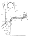
図1は、ガラスリボン103を加工するための装置101を示したものである。ガラスリボン103は様々なガラスリボン供給源から提供することができる。図1ではガラスリボン103の供給源105の2つの例を示しているが、さらなる例では他の供給源を提供してもよい。図1に示したように、例えば、ガラスリボン103の供給源105はダウンドローガラス成形装置107を含んでもよい。概略的に図示したが、ダウンドローガラス成形装置107は、トラフ111の下部に成形用ウェッジ109を含むものとすることができる。動作中、溶融ガラス113がトラフ111から溢れ出し、成形用ウェッジ109の相対する面115、117を下方に流れ得る。続いて、溶融ガラスの2つのシートが、成形用ウェッジ109の底部119から延伸されるときに融合する。したがって、ガラスリボン103が下方へ融合延伸されると、このガラスリボン103は成形用ウェッジ109の底部119から離れ、直接、ダウンドローガラス成形装置107の下流に位置する下降ゾーン123へと下向き121に通過し得る。
FIG. 1 shows an
図2に断面で示されているように、ガラスリボン103は、一対の対向エッジ部分201、203と、この対向エッジ部分201、203の間に広がる中心部分205とを含み得る。ガラスリボンのエッジ部分201、203は、ダウンドローフュージョンプロセスに起因して、ガラスリボン103の中心部分205の厚さ「T2」より厚い厚さ「T1」を有する、対応するビード207、209を含む可能性がある。装置101は、薄い中心部分205を有するガラスリボン103を処理するよう設計され得るものであり、例えばそのガラスリボンの厚さ「T2」は約20μmから約300μmの範囲、例えば約50μmから約300μmの範囲、例えば約85μmから約150μmの範囲などとし得るが、さらなる例において他の厚さを有するガラスリボンを処理することもできる。
As shown in cross section in FIG. 2, the
図1に戻るが、ガラスリボン103の供給源105の別の例を、ガラスリボン103のコイル状スプール124を含むものとすることができる。例えば、ダウンドローガラス成形装置107などを用いてガラスリボンを延伸した後、このガラスリボン103をコイル状スプール124へと巻回してもよい。エッジ部分201、203の厚さが厚くなると、ガラスリボンの亀裂または破損を防ぐために、最小曲げ半径は大きくなるであろう。したがって、ガラスリボン103をコイル状に巻く場合には比較的大きい曲げ半径となり得、その結果、ガラスリボン103の所与の長さが要するコイル状スプール124の直径「D1」は、比較的大きいものとなるであろう。すなわち、供給源105がコイル状スプール124を含む場合、ガラスリボン103を下向き121に下降ゾーン123へと通過させるために、ガラスリボン103のコイル状スプール124からガラスリボン103を解くようにしてもよい。
Returning to FIG. 1, another example of the
この装置は、下降ゾーン123の下流にさらに曲げゾーン125を含んでもよい。曲げゾーン125においては、ガラスリボン103の上表面127が曲げゾーン125内で半径「R」で曲がっている上方凹状表面を含むように、装置101をガラスリボン103が湾曲経路を通って移動できるよう設計されたものとしてもよい。半径「R」は、ガラスリボン103内の応力集中を避けるよう、ガラスリボン103の最小曲げ半径よりも大きいものとしてもよい。ガラスリボン103は、曲げゾーン125へと進入していくガラスリボン103の曲げ前の部分131がガラスリボン103の曲げ後の部分133に対して種々の角度で延在し得るような、曲げゾーン125の範囲内で種々の弓形を通って延在するものとしてもよい。例えば、図1に示すように、曲げ前の部分131と曲げ後の部分133との間の角度「A」は鋭角を有するものとすることができるが、さらなる例においては、上方凹状表面127を提供した状態のまま、90°以上の角度を実現することもできる。
The apparatus may further include a
装置101は、曲げゾーン125内のガラスリボンの下方部分137の高度が、切断ゾーン147に繋がる支持部分を通過しているガラスリボンの横方向移動高度よりも低い例において、随意的な曲げ支持部材135をさらに含んでもよい。曲げ支持部材135を提供する場合には、この曲げ支持部材135を、ガラスリボン103の中心部分205の対向面139、141に触れることなくガラスリボン103を支持するよう設計された、非接触式支持部材135を含むものとしてもよい。例えば、曲げ支持部材135は、ガラスリボンを曲げ支持部材135と接触させないように空気のクッションを提供するよう構成された、1以上の湾曲エアバーを含んでもよい。
The
装置101の例は、ガラスリボン103の移動方向213に対してガラスリボン103を正しい横方向位置に配置するのを助けるために、横方向ガイド143、145を含み得る。例えば図2に概略的に示すように、横方向ガイドは夫々、対向エッジ部分201、203のうちの対応する一方に係合するよう構成されたローラ211を含み得る。横方向ガイド143、145が夫々エッジ部分201、203に加える対応する力213、215により、ガラスリボン103の移動方向213を横切る軸217の方向に沿って、適切な横方向の配置に、ガラスリボン103を適切にシフトかつ位置合わせするのを助けることができる。
The
さらに図示したように、横方向ガイド143、145は、ガラスリボン103の中心部分205と係合することなくエッジ部分201、203と係合するように設計することができる。したがって、ガラスリボン103の中心部分205の対向面139、141は、横方向ガイド143、145がガラスリボン103の中心部分205の対向面139、141のいずれかと係合した場合に生じる可能性のある望ましくない引っかき傷やその他の表面汚染を回避し、清浄な表面を維持することができる。さらに、横方向ガイド143、145を、ガラスリボン103がガラスリボン103の移動方向213を横切る軸217周りに屈曲しているときに、ガラスリボン103と係合させてもよい。ガラスリボン103を曲げ支持部材135上で屈曲させると、その屈曲部分に亘ってガラスリボン103の剛性を増加させることができる。したがって、横方向ガイド143、145を、ガラスリボン103が曲げ支持部材135上を通過しているときに、屈曲状態のガラスリボン103と係合させてもよい。こうすることで、曲げ支持部材135上を通過しているガラスリボン103を横方向に位置合わせするときに、横方向ガイド143、145が加える力213、215によって、ガラスリボンの形が曲がったり、あるいはガラスリボンの形の安定性が乱れたりする可能性が低くなる。
As further illustrated, the lateral guides 143, 145 can be designed to engage the
この装置は、曲げゾーン125の下流に切断ゾーン147をさらに含んでもよい。一例において、装置101は、切断ゾーン147においてガラスリボン103を屈曲させて、屈曲配置を有する屈曲ターゲットセグメント151を切断ゾーン147内で提供するよう構成された、切断支持部材149を含んでもよい。ターゲットセグメント151を切断ゾーン147内で屈曲させると、切断処理中にガラスリボン103を安定させる助けとなり得る。このように安定させることで、対向エッジ部分201、203の少なくとも一方をガラスリボン103の中心部分205から分離させる処理の間に、ガラスリボンの形を曲げたりあるいは乱したりすることを防ぐ助けとなり得る。
The apparatus may further include a
切断支持部材149を提供する場合には、この切断支持部材149を、ガラスリボン103の対向面139、141に触れることなくガラスリボン103を支持するよう設計された、非接触式切断支持部材149を含むものとしてもよい。例えば、図3を参照するが、非接触式切断支持部材149は、ガラスリボン103と切断支持部材149との間に間隔を空けさせてガラスリボン103の中心部分205が切断支持部材149と接触しないように空気のクッションを提供するよう構成された、1以上の湾曲エアバーを含んでもよい。
When the cutting
図3を参照すると、正圧ポート303を提供するよう構成された複数の通路301を切断支持部材149に設け、空気流305を正圧ポート303から屈曲ターゲットセグメント151へと強制的に通し、屈曲ターゲットセグメント151を非接触で支持するエアクッション307を生成するようにしてもよい。随意的に、複数の通路301は負圧ポート309を含んでもよく、この負圧ポート309は、正圧ポート303が生成したエアクッションからの力を部分的に弱めるための吸引力を生成するよう、空気流311を屈曲ターゲットセグメント151から引き込むことができるようなものである。正圧ポートと負圧ポートとを組み合わせることで、切断処理中の間、屈曲ターゲットセグメント151を安定させるのを助けることができる。実際に、正圧ポート303は、ガラスリボン103の中心部分205と切断支持部材149との間のエアクッション307の高さを所望の高さで維持するのを助けることができる。同時に、負圧ポート309は、ガラスリボン103が切断支持部材149上を移動方向213に通過しているときに、ガラスリボン103が波打ったり、あるいはガラスリボン103の屈曲ターゲットセグメント151のいくつかの部分がそのターゲットセグメントの他の部分から離れて浮いてしまったりすることのないように、ガラスリボンを切断支持部材149の方へと引っ張るのを助けることができる。
Referring to FIG. 3, a plurality of
切断ゾーン147において屈曲ターゲットセグメント151を提供することで、切断ゾーン147に亘ってガラスリボン103の剛性を高めることも可能となる。したがって、図2に示すように、ガラスリボン103が切断ゾーン147内で切断支持部材149上を通過するとき、随意的な横方向ガイド219、221を屈曲状態のガラスリボン103と係合させてもよい。こうすることで、切断支持部材149上を通過しているガラスリボン103を横方向に位置合わせするときに、横方向ガイド219、221が加える力223、225によって、ガラスリボンの形が曲がったり、あるいはガラスリボンの形の安定性が乱れたりする可能性が低くなる。そのため、ガラスリボン103の移動方向213を横切る軸217の方向に沿って屈曲ターゲットセグメント151を適切な横方向の配置に微調整するために、随意的な横方向ガイド219、221を提供してもよい。
By providing the
上で明記したように、屈曲配置の屈曲ターゲットセグメント151を切断ゾーン147内で提供することが、切断処理中にガラスリボン103を安定させる助けとなり得る。この安定化が、対向エッジ部分201、203のうちの少なくとも一方を分離する処理の間に、ガラスリボンの形を曲げたりあるいは乱したりするのを防ぐ助けとなり得る。さらに、屈曲ターゲットセグメント151の屈曲配置がターゲットセグメントの剛性を増加させ、屈曲ターゲットセグメント151の横方向の配置の随意的な微調整を可能にし得る。したがって、ガラスリボン103の中心部分205から対向エッジ部分201、203のうちの少なくとも一方を分離する処理の際に、ガラスリボン103の中心部分205の清浄な対向面139、141に接触することなく、比較的薄いガラスリボン103を効果的に安定させかつ適切に横方向に配置することができる。
As specified above, providing a
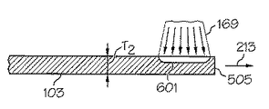
ガラスリボン103の屈曲ターゲットセグメント151の安定化および剛性は、移動方向213を横切る軸217の方向に沿って上方凸状表面および/または上方凹状表面を含むように、ターゲットセグメントを屈曲させることにより高めることができる。例えば、図3に示すように、屈曲ターゲットセグメント151は上向き凸状表面313を有する屈曲配置を含む。本開示のいくつかの例は、図示のエアバーのような切断支持部材149の上向き凸状支持表面315で、屈曲ターゲットセグメント151を支持するものを含むものとすることができる。図3に示したように、上向き凸状支持表面315を有する切断支持部材149を提供することで、説明したような上向き凸状表面313を有する屈曲配置を達成するようにガラスリボン103を切断ゾーン147内で同様に屈曲させることができる。
Stabilization and rigidity of the
別の例においては、図4に示したように、図3で説明した切断支持部材149に類似の別の切断支持部材401を提供してもよい。ただし、図4に示したように、切断支持部材401は上向き凹状表面405を有する屈曲配置の屈曲ターゲットセグメント403を支持するように提供され得る。そのため、本開示のさらなる例は、図示のエアバーのような切断支持部材401の上向き凹状支持表面407で、屈曲ターゲットセグメント403を支持するものを含ものとすることができる。図4に示したように、上向き凹状支持表面407を有する切断支持部材401を提供することで、説明したような上向き凹状表面405を有する屈曲配置を達成するようにガラスリボン103を切断ゾーン147内で同様に屈曲させることができる。
In another example, as shown in FIG. 4, another cutting
装置101は、ガラスリボン103のエッジ部分201、203を中心部分205から分離するよう構成された、さまざまな切断機器をさらに含むことができる。一例においては図1に示すように、一例のガラス切断機器153が、屈曲ターゲットセグメント151の上向き表面の一部を照射しかつ加熱する光送出装置155を含み得る。一例では光送出装置155を、図示のレーザ161のような放射源を含むものとすることができるが、さらなる例では他の放射源を提供してもよい。光送出装置155は、円偏光子163、ビーム拡大器165、およびビーム成形装置167をさらに含んでもよい。
The
光送出装置155は、放射源(例えば、レーザ161)からの放射ビーム(例えば、レーザビーム169)の向きを変えるための、例えばミラー171、173、および175などの光学素子をさらに含んでもよい。放射源は、ガラスリボン103に入射する位置でガラスリボン103を加熱するのに適した波長及び出力を有するレーザビームを放出するよう構成された、図示のレーザ161を含むものとすることができる。一実施の形態において、レーザ161はCO2レーザを含み得るが、さらなる例においては他の種類のレーザを使用することもできる。
The
レーザ161は、断面(すなわち、レーザビームの長手軸に直角なレーザビーム断面)が実質的に円形のレーザビーム169を最初に放出するよう構成されたものでもよい。光送出装置155は、ビームがガラスリボン103に入射するときに著しく細長い形状を有するようにレーザビーム169を変形させるよう動作可能なものである。図2に示したように、この細長い形状が細長い放射ゾーン227を生成し得る。細長い放射ゾーン227は図示のような楕円形のフットプリントを含み得るが、さらなる例においては他の形状を提供してもよい。楕円形フットプリントは、屈曲ターゲットセグメント151、403の、上向き凸状表面313または上向き凹状表面405上に位置付けられ得る。
The
ビーム強度がそのピーク値の1/e2に減少した点を、楕円形フットプリントの境界と判定することができる。レーザビーム169は円偏光子163を通過し、そしてその後ビーム拡大器165を通過して拡大される。拡大したレーザビームは次いでビーム成形装置167を通過して、屈曲ターゲットセグメント151、403の表面上に楕円形フットプリントを生成するビームを形成する。ビーム成形装置167は、例えば、1以上のシリンドリカルレンズを含んでもよい。ただし、レーザ161が放出したビームを成形して屈曲ターゲットセグメント151、403上に楕円形フットプリントを生成することが可能な任意の光学素子を使用し得ることを理解されたい。
The point where the beam intensity has decreased to 1 / e 2 of its peak value can be determined as the boundary of the elliptical footprint. The
楕円形フットプリントは、実質的に短軸より長い主軸を含み得る。いくつかの実施形態において、例えば、主軸は短軸の少なくとも約10倍長い。しかしながら、細長い放射ゾーンの長さおよび幅は、所望の分離速さ、所望の初期クラックサイズ、ガラスリボンの厚さ、レーザ出力などに依存し、さらに必要に応じて放射ゾーンの長さおよび幅を変化させてもよい。 The elliptical footprint may include a major axis that is substantially longer than the minor axis. In some embodiments, for example, the major axis is at least about 10 times longer than the minor axis. However, the length and width of the elongated emission zone depends on the desired separation speed, desired initial crack size, glass ribbon thickness, laser power, etc. It may be changed.
図1にさらに示したように、この例のガラス切断機器153は、屈曲ターゲットセグメント151の上向き表面の加熱部分を冷却するよう構成された、冷却剤流体送出装置159をさらに含んでもよい。冷却剤流体送出装置159は、冷却剤ノズル177、冷却剤供給源179、および、冷却剤ノズル177に冷却剤を運ぶことの可能な関連する導管181を含むものとすることができる。
As further shown in FIG. 1, the
図3を参照すると、冷却剤ノズル177は、冷却剤流体の冷却剤ジェット317を屈曲ターゲットセグメント151、403の上向き表面313、405に送出するように構成することができる。冷却剤ノズル177は、所望サイズの冷却ゾーン319を形成するよう、種々の内径を有するものとすることができる。細長い放射ゾーン227と同様、冷却剤ノズル177の直径、そしてそれに続く冷却剤ジェット317の直径は、必要に応じて個々の処理条件に対し変化させてもよい。いくつかの実施形態において、ガラスリボンの冷却剤が直接当たる部分(冷却ゾーン)の直径を、放射ゾーン227の短軸より短いものとしてもよい。しかしながら、特定の他の実施形態においては、速さ、ガラス厚、レーザ出力などの処理条件に基づき、冷却ゾーンの直径を細長い放射ゾーン227の短軸より長いものとしてもよい。実際に、冷却剤ジェットの(断面)形状は円形以外のものでもよく、さらに例えば、冷却ゾーンがガラスリボンの表面上に円形のスポットではなく直線を形成するよう、冷却剤ジェットを扇形としてもよい。直線状の冷却ゾーンを、例えば細長い放射ゾーン227の主軸と垂直に配向してもよい。他の形状が有益なこともあり得る。
With reference to FIG. 3, the
一例において、冷却剤ジェット317は水を含むが、冷却剤ジェット317を、ガラスリボン103の屈曲ターゲットセグメント151、403の上向き表面313、405を染色または損傷することのない任意の適切な冷却用流体(例えば、液体ジェット、気体ジェット、またはその組合せ)としてもよい。冷却剤ジェット317をガラスリボン103の表面に送出することで、冷却ゾーン319を形成することができる。図示のように、冷却ゾーン319を細長い放射ゾーン227の後に追跡させることで、以下でより詳細に説明する本開示の態様によって形成される初期クラックを伝播させることができる。
In one example, the
レーザ装置155および冷却装置159を用いて加熱および冷却を組み合わせることにより、他の分離技術で形成され得るような中心部分205の対向エッジ223、225における望ましくない残留応力、微小クラック、または他の凹凸を、最小限に抑えたあるいは排除した状態で、中心部分205からエッジ部分201、203を効果的に分離することができる。さらに、切断ゾーン147内における屈曲ターゲットセグメント151の屈曲配置により、ガラスリボン103を適切に位置付けかつ安定化させて、分離処理中の対向エッジ223、225の正確な分離を助けることができる。さらに、上向き凸状支持表面315の凸状表面トポグラフィにより、エッジ部分(例えば、図3の破線の符号201参照)は中心部分205からすぐに離れて移動し得るため、エッジ部分が続いて中心部分205の清浄な面139、141および/または高品質な対向エッジ223、225と係合する(そしてそれにより損傷させる)可能性が低減する。
By combining heating and cooling using
図1に戻ると、装置101は切断ゾーン147の下流に、分離したエッジ部分201、203および/またはガラスリボン103の中心部分205を、さらに処理するよう構成された構造体を含んでもよい。例えば、1以上のガラスリボンチョッパ183を提供し、セグメントを廃棄または再利用するために叩き切ったり、切り裂いたり、割ったり、あるいはそれ以外の方法で圧縮したりしてもよい。
Returning to FIG. 1, the
ガラスリボン103の中心部分205を、光学部品に組み込むためのガラスシートへと切断することでさらに処理してもよい。例えば、装置101は、ガラスリボン103の移動方向213を横切る軸217に沿ってガラスリボン103の中心部分205を分離するよう構成された、別の分離用機器(図示なし)を含んでもよい。あるいは、図1に示したように、ガラスリボン103の中心部分205をコイル状に巻いて、後の処理のためにコイル状スプール185としてもよい。図示のようにエッジ部分201、203を除去すると、結果として対応するビード207、209が除去される。ビードが除去されると最小曲げ半径が小さくなり、ガラスリボン103の中心部分205はより効率的にコイル状スプール185へと巻回することができる。図1に概略的に表したように、コイル状スプール185の無駄な中心コア部187は、コイル状スプール124の無駄な中心コア部189と比較して著しく縮小される。したがって、中心部分205のコイル状スプール185の直径「D2」は、同じ長さの処理前のガラスリボンをコイル状スプール124の状態で保管するのに必要な直径「D1」よりも著しく小さくなる。
The
図1にさらに示されているが、装置101は、ガラスリボン103の少なくとも中心部分205を切断ゾーン147から下流に案内するためのさらなる非接触式支持部材をさらに含んでもよい。例えば図示のように、ガラスリボンの中心部分205をその表面に接触することなく最終処理へと案内するために、この装置は第1エアバー188および第2エアバー190を含んでもよい。2つの支持部材が図示されているが、さらなる例においては、単一の支持部材または3以上の支持部材を提供してもよい。さらに図示のように、エッジ部分をガラスリボンチョッパへと案内するのを可能とするように、随意的な支持部材191を設けてもよい。エッジ部分がガラスリボンチョッパ183へと進むときの動きが拘束および/または制限されるのを低減するために、随意的な支持部材191は随意的にエアバーまたは低摩擦表面を含んでもよい。
As further shown in FIG. 1, the
ここで、装置101を用いてガラスリボンを加工する方法について説明する。図1に示したように、この方法は、ガラスリボン103を供給源105に対して下向き121に下降ゾーン123に通過させるステップを含んでもよい。図示のように、ガラスリボン103は実質的に鉛直に下向き121に移動し得るが、さらなる例においては、その下向きの方向を傾いたものとしてもよく、このときガラスリボン103は傾斜した配置で下向きに移動することができる。
Here, a method of processing a glass ribbon using the
この方法は、下降ゾーン123の下流の曲げゾーン125においてガラスリボン103を屈曲させるステップをさらに含んでもよく、このときガラスリボン103は、曲げゾーン125を通過している間、上方凹状表面127を含む。図示のように、下方部分137は切断ゾーン147内の屈曲ターゲットセグメント151よりも著しく低い位置となり得るが、さらなる例においては下方部分137を屈曲ターゲットセグメントと実質的に同じ高度または屈曲ターゲットセグメントよりも高い高度にさえすることも可能である。著しく低い位置に下方部分137を設定すると、図示のように、装置101の支持部材(例えば、支持部材135)と係合する前にガラスリボンが既定量だけ溜まった状態を生じさせることができる。したがって、下方部分137より上流の振動や他の乱れを、曲げゾーン内に溜められたガラスリボンで吸収することができる。さらに、供給源105がガラスリボン103を下降ゾーン123にどれほど速く送り込んでいたとしても、これとは無関係に、ガラスリボン103を切断ゾーン147に通過させる際には実質的に一定速度または所望の既定速度でガラスリボン103を引き込むことができる。したがって、曲げゾーン125内に溜め部分を設けることで、切断ゾーン147内でのガラスリボン103のさらなる安定化を可能にすると同時に、ガラスリボン103を切断ゾーン147に実質的に一定のまたは既定の速度で通過させることもできる。
The method may further include bending the
溜め部分が提供される場合には、種々の技術を用いて曲げゾーン125内のガラスリボン103の所望の溜め部分を維持するのを助けることができる。例えば、近接センサ129または他の機器を使用して溜まったリボンの位置を感知し、供給源105が下降ゾーン123に送り込むガラスリボンの速度を調整して、ガラスリボン103の溜め部分を適切なものとすることができるであろう。
If a reservoir portion is provided, various techniques can be used to help maintain the desired reservoir portion of the
さらなる例において、この方法は、ガラスリボンの向きを変えさせて移動方向213に移動させるように、曲げゾーン125の下流でガラスリボン103を屈曲させるステップをさらに含んでもよい。図示のように、曲げ支持部材135が、ガラスリボン103の中心部分205に接触することなく所望の方向転換をもたらすよう設計された屈曲エアバーを含んでもよい。さらに、この方法は、ガラスリボン103をガラスリボン103の移動方向213に対して正しい横方向位置に配置するのを助けるために、曲げ支持部材によって屈曲されているガラスリボン103を横方向ガイド143、145を用いて配置するステップをさらに随意的に含んでもよい。
In a further example, the method may further include bending the
この方法は、ガラスリボン103を曲げゾーン125の下流の切断ゾーン147へと通過させ、かつこのときに、ガラスリボン103を切断ゾーン147において屈曲させて、屈曲配置を有する屈曲ターゲットセグメント151、403を切断ゾーン147内で提供するステップ、をさらに含んでもよい。
In this method, the
図1に示したように、ターゲットセグメント151の屈曲配置が上向き凸状表面313を含むようにガラスリボン103を屈曲させてもよい。一例において、この方法は、説明した湾曲エアバーを備えた切断支持部材149で屈曲ターゲットセグメント151を支持するステップを含んでもよい。図示のように切断支持部材149は、ターゲットセグメント151を屈曲させて上向き凸状表面313を得るように構成された、上向き凸状支持表面315を含んでもよい。
As shown in FIG. 1, the
あるいは、図4に示すように、ターゲットセグメント403の屈曲配置が上向き凹状表面405を含むようにガラスリボン103を屈曲させてもよい。一例において、この方法は、説明した湾曲エアバーを備えた切断支持部材401で屈曲ターゲットセグメント403を支持するステップを含んでもよい。図示のように切断支持部材401は、ターゲットセグメント403を屈曲させて上向き凹状表面405を得るように構成された、上向き凹状支持表面407を含んでもよい。
Alternatively, as shown in FIG. 4, the
図1に示したように、この方法は、切断ゾーン147内において、少なくとも一方のエッジ部分201、203を屈曲ターゲットセグメント151、403の中心部分205から分離するステップをさらに含んでもよい。図2に示すように、本開示の例は両方のエッジ部分201、203を中心部分205から分離するものを含み得るが、さらなる例においては単一のエッジ部分を中心部分から分離させてもよい。さらに、図2に示すように、両方のエッジ部分201、203は中心部分205から同時に分離されるが、さらなる例においては、一方のエッジ部分を他方のエッジ部分の前に分離してもよい。
As shown in FIG. 1, the method may further include separating at least one
分離するステップはさまざまな技術を取り入れることができる。例えば、説明した光送出装置155と冷却剤流体送出装置159とを含み得るガラス切断機器153によって、エッジ部分201、203を中心部分205から分離することができる。
The separating step can incorporate various techniques. For example, the
分離処理開始の一例について図5〜7で説明する。制御された表面傷をガラスリボンの分離位置に生成するため、図5に示すように、スクライバ503または他の機械的機器がスクライブ用の針で初期クラック501を生成してもよい。図示のようにスクライバ503は先端部を含むが、さらなる例ではエッジブレードや他のスクライブ技術を使用してもよい。さらに、初期クラック501または他の表面欠陥を、エッチング、レーザ衝撃、または他の技術によって形成してもよい。
An example of the start of the separation process will be described with reference to FIGS. In order to generate a controlled surface flaw at the separation position of the glass ribbon, a
さらに図5に示したように、初期クラック501または表面欠陥は、最初に、移動方向213に通過しているガラスリボン103の先端エッジ505に隣接させて形成してもよい。図6に示すように、細長い放射ゾーン227を上向き凸状表面313または上向き凹状表面405上に形成してもよい。細長い放射ゾーン227が移動方向213に引き伸ばされると、初期クラック50が伝播し、ガラスリボン103の厚さ「T2」の一部に亘って延在する細長いクラック部分601となる。図7に示すように、冷却剤ジェット317がその後冷却ゾーン319に接触して細長いクラック部分601をガラスリボン103の厚さ「T2」に完全に貫通させてさらに伝播させ、図7に参照数字701で示すように対応するエッジ部分201、203を中心部分205から分離する。
Further, as shown in FIG. 5, the
図3に示すように、中心部分205に、内部応力プロファイルが減少し、クラックあるいは他の欠陥が減少した高品質な対向エッジ229、231を持たせたまま、分離された対向エッジ部分201、203を効果的に除去することができる。したがって、中心部分205は屈曲させることが可能であり、例えばエッジの品質が悪い場合に生じ得る亀裂を生じさせることなくコイル状スプール185に巻回などすることができる。さらに、エッジの品質が低いと、コイル状に巻く際にガラスの破片や他の欠陥を含むエッジ部分で中心部分205に傷を生じさせる可能性もあるが、高品質のエッジではこのような傷を回避できる。
As shown in FIG. 3, the separated opposing
この方法は、切断支持部材149、401の上向き凸状表面315または上向き凹状表面407で、屈曲ターゲットセグメント151、403を支持するステップをさらに含んでもよい。例えば、切断ゾーン147内でエッジ部分201、203を屈曲ターゲットセグメント151、403の中心部分205から分離する際に、説明したエアバーの凸状表面315または凹状表面407で屈曲ターゲットセグメント151、403を支持してもよい。
The method may further include supporting the
この方法はさらに、分離するステップの後に、ガラスリボン103の中心部分205をコイル状に巻いてコイル状スプール185とするステップをさらに含んでもよい。したがって、続く発送処理あるいはガラスシートにする処理のために、ガラスリボンの高品質な中心部分205を効率的にコイル状に巻いてコイル状スプール185とすることができる。
The method may further include the step of coiling the
図8は、ガラスリボン103の中心部分205から対向エッジ部分201、203の少なくとも一方を分離するよう構成された、別の装置801を示したものである。図示のように、ガラスリボン103は曲げゾーン125内で切断することが可能であり、さらに中心部分205をその後、例えば支持部材803、807によって案内してもよい。図示のように、支持部材803、807はガラスリボンの中心部分205の清浄な光学表面に接触することなくこの中心部分205を支持するよう構成された、説明したエアバーなどのような非接触式支持部材を備えたものでもよい。ガラスリボン103の中心部分205を、その後コイル状スプール185へと巻くように案内してもよい。随意的な横方向ガイド805を提供してガラスリボンの中心部分205の横方向の配置を助け、ガラスリボン103が、対応する支持部材803、807の支持表面から浮かび上がるのを防ぐことができる。
FIG. 8 shows another
図8に示した装置801を用いてガラスリボンを加工する方法については説明しない。この方法は、ガラスリボン103を供給源105に対して下向き121に、下降ゾーン123に通過させるステップを含み得る。この方法は、下降ゾーン123の下流の曲げゾーン125においてガラスリボンを屈曲させるステップをさらに含んでもよい。屈曲されると、ガラスリボン103は曲げゾーン125を通過している間、上方凹状表面127を含む。この方法は、エッジ部分201、203の少なくとも一方をターゲットセグメント809の中心部分205から、曲げゾーン125内において分離するステップをさらに含む。
A method for processing a glass ribbon using the
図示のように、曲げゾーン125内での分離は、ターゲットセグメント809を支持構造で必ずしも支持することなく行うことができる。むしろ重力の働きにより、エッジ部分201、203は中心部分205から離れるように引っ張られる。このため、エッジ部分201、203は一旦分離されると、重力の影響を受けて中心部分205から自然に離れ得る。したがって、分離されたエッジ部分201、203と中心部分205の清浄な表面とが偶発的に接触する可能性は低減される。
As shown, the separation within the bending
図示のように、図8に示した分離するステップはガラス切断機器153を用いて実行され得るが、さらなる例においては他の切断機器を取り入れることもできる。図8にさらに示されているように、一旦分離が完了すると、この方法は、中心部分205を例えば支持部材803、807で案内しかつこの中心部分205をコイル状に巻いてコイル状スプール185とする、随意的なステップをさらに含んでもよい。
As shown, the separating step shown in FIG. 8 may be performed using a
請求される発明の精神および範囲から逸脱することなく、種々の改変および変形が作製可能であることは当業者には明らかであろう。 It will be apparent to those skilled in the art that various modifications and variations can be made without departing from the spirit and scope of the claimed invention.
103 ガラスリボン
105 供給源
123 下降ゾーン
125 曲げゾーン
147 切断ゾーン
149 切断支持部材
151,403 屈曲ターゲットセグメント
153 ガラス切断機器
155 光送出装置
159 冷却剤流体送出装置
185 コイル状スプール
201,203 エッジ部分
205 中心部分
DESCRIPTION OF
Claims (16)
(I)一対の対向エッジ部分と該対向エッジ部分間に横方向に広がる中心部分とを有するガラスリボンの供給源を提供するステップ、
(II)前記ガラスリボンを前記供給源に対して下向きに、下降ゾーンに通過させるステップ、
(III)前記ガラスリボンを前記下降ゾーンの下流の曲げゾーンにおいて屈曲させるステップであって、前記ガラスリボンが、該曲げゾーンを通過している間、上方凹状表面を含んでいる、ステップ、
(IV)前記ガラスリボンを前記曲げゾーンの下流の切断ゾーンへと通過させるステップ、
(V)前記ガラスリボンを前記切断ゾーンにおいて屈曲させて、屈曲配置を有する屈曲ターゲットセグメントを前記切断ゾーン内で提供するステップ、および、
(VI)前記切断ゾーン内において、前記エッジ部分の少なくとも一方を前記屈曲配置を有する前記屈曲ターゲットセグメントの前記中心部分から分離させるステップ、
を含むことを特徴とする方法。 A method of processing a glass ribbon,
(I) providing a source of glass ribbon having a pair of opposing edge portions and a central portion extending laterally between the opposing edge portions;
(II) passing the glass ribbon downwardly with respect to the source into a descending zone;
(III) the glass ribbon comprising the steps of bending downstream of the bending zone of the descending zone, the glass ribbon, while passing through the flexural zone includes an upper concave surface, step,
(IV) passing the glass ribbon through a cutting zone downstream of the bending zone;
(V) bending the glass ribbon in the cutting zone to provide a bent target segment having a bent arrangement in the cutting zone; and
(VI) separating at least one of the edge portions from the central portion of the bent target segment having the bent arrangement in the cutting zone;
A method comprising the steps of:
Applications Claiming Priority (4)
| Application Number | Priority Date | Filing Date | Title |
|---|---|---|---|
| US201161469321P | 2011-03-30 | 2011-03-30 | |
| US61/469,321 | 2011-03-30 | ||
| US13/182,029 | 2011-07-13 | ||
| US13/182,029 US9790121B2 (en) | 2011-03-30 | 2011-07-13 | Methods of fabricating a glass ribbon |
Related Child Applications (1)
| Application Number | Title | Priority Date | Filing Date |
|---|---|---|---|
| JP2016197896A Division JP6794209B2 (en) | 2011-03-30 | 2016-10-06 | Glass ribbon processing method |
Publications (2)
| Publication Number | Publication Date |
|---|---|
| JP2012211074A JP2012211074A (en) | 2012-11-01 |
| JP6022790B2 true JP6022790B2 (en) | 2016-11-09 |
Family
ID=45894273
Family Applications (3)
| Application Number | Title | Priority Date | Filing Date |
|---|---|---|---|
| JP2012075795A Expired - Fee Related JP6022790B2 (en) | 2011-03-30 | 2012-03-29 | Glass ribbon processing method |
| JP2016197896A Active JP6794209B2 (en) | 2011-03-30 | 2016-10-06 | Glass ribbon processing method |
| JP2019072642A Active JP6757440B2 (en) | 2011-03-30 | 2019-04-05 | Glass ribbon processing method |
Family Applications After (2)
| Application Number | Title | Priority Date | Filing Date |
|---|---|---|---|
| JP2016197896A Active JP6794209B2 (en) | 2011-03-30 | 2016-10-06 | Glass ribbon processing method |
| JP2019072642A Active JP6757440B2 (en) | 2011-03-30 | 2019-04-05 | Glass ribbon processing method |
Country Status (7)
| Country | Link |
|---|---|
| US (1) | US9790121B2 (en) |
| EP (2) | EP2505566B1 (en) |
| JP (3) | JP6022790B2 (en) |
| KR (2) | KR101719835B1 (en) |
| CN (2) | CN102730940B (en) |
| IN (1) | IN2012DE00923A (en) |
| TW (1) | TWI576319B (en) |
Cited By (1)
| Publication number | Priority date | Publication date | Assignee | Title |
|---|---|---|---|---|
| WO2022250265A1 (en) * | 2021-05-27 | 2022-12-01 | 주식회사 디에이테크놀로지 | Laser notching apparatus for secondary battery electrode |
Families Citing this family (55)
| Publication number | Priority date | Publication date | Assignee | Title |
|---|---|---|---|---|
| US9199816B2 (en) * | 2010-11-04 | 2015-12-01 | Corning Incorporated | Methods and apparatus for guiding flexible glass ribbons |
| US9790121B2 (en) * | 2011-03-30 | 2017-10-17 | Corning Incorporated | Methods of fabricating a glass ribbon |
| US9428359B2 (en) * | 2011-11-30 | 2016-08-30 | Corning Incorporated | Methods and apparatuses for conveying flexible glass substrates |
| TWI597245B (en) * | 2012-09-25 | 2017-09-01 | 康寧公司 | Methods of processing a continuous glass ribbon |
| US9038414B2 (en) * | 2012-09-26 | 2015-05-26 | Corning Incorporated | Methods and apparatuses for steering flexible glass webs |
| US9216924B2 (en) * | 2012-11-09 | 2015-12-22 | Corning Incorporated | Methods of processing a glass ribbon |
| WO2014077117A1 (en) * | 2012-11-13 | 2014-05-22 | 日本電気硝子株式会社 | Sheet glass manufacturing method and manufacturing device |
| US20140144965A1 (en) * | 2012-11-29 | 2014-05-29 | James William Brown | Method to manipulate brittle material sheet compound shape |
| CN105189374A (en) * | 2012-11-29 | 2015-12-23 | 康宁股份有限公司 | A process and apparatus for working on a thin glass web material |
| WO2014085357A1 (en) * | 2012-11-29 | 2014-06-05 | Corning Incorporated | Methods and apparatus for fabricating glass ribbon of varying widths |
| US9362546B1 (en) | 2013-01-07 | 2016-06-07 | Quantumscape Corporation | Thin film lithium conducting powder material deposition from flux |
| EP2950969A4 (en) * | 2013-01-30 | 2016-10-19 | Corning Inc | Apparatus and methods for continuous laser cutting of flexible glass |
| WO2014179422A1 (en) | 2013-05-03 | 2014-11-06 | Corning Incorporated | Methods and apparatus for conveying a glass ribbon |
| WO2014192482A1 (en) * | 2013-05-28 | 2014-12-04 | 旭硝子株式会社 | Glass substrate cutting method and glass substrate manufacturing method |
| JP6112301B2 (en) * | 2013-08-28 | 2017-04-12 | 日本電気硝子株式会社 | Glass film ribbon manufacturing apparatus, glass film ribbon manufacturing method, and glass roll |
| US9932259B2 (en) * | 2013-08-28 | 2018-04-03 | Nippon Electric Glass Co., Ltd. | Glass film ribbon manufacturing method and glass film ribbon manufacturing device |
| JP6056711B2 (en) * | 2013-08-28 | 2017-01-11 | 日本電気硝子株式会社 | Thin glass cutting method and glass article manufacturing method |
| WO2015029669A1 (en) * | 2013-08-28 | 2015-03-05 | 日本電気硝子株式会社 | Method for conveying thin sheet glass, conveyance device, cutting method, and method for producing glass article |
| KR102221540B1 (en) * | 2013-08-28 | 2021-03-02 | 니폰 덴키 가라스 가부시키가이샤 | Glass film ribbon manufacturing method and glass film ribbon manufacturing device |
| JP6056710B2 (en) * | 2013-08-28 | 2017-01-11 | 日本電気硝子株式会社 | Thin glass conveying method and conveying device |
| JP6331087B2 (en) * | 2013-08-28 | 2018-05-30 | 日本電気硝子株式会社 | Glass film ribbon manufacturing method and glass film ribbon manufacturing apparatus |
| ES2890654T3 (en) | 2013-10-07 | 2022-01-21 | Quantumscape Battery Inc | Garnet Materials for Li Secondary Batteries and Manufacturing Methods and Use of the Garnet Materials |
| US10246365B2 (en) * | 2013-10-09 | 2019-04-02 | Corning Incorporated | Apparatus and method for forming thin glass articles |
| KR101515807B1 (en) * | 2013-11-04 | 2015-05-07 | 코닝정밀소재 주식회사 | Method and appratus for manufacuring a roll |
| KR101515806B1 (en) * | 2013-11-04 | 2015-05-04 | 코닝정밀소재 주식회사 | Method and apparatus of manufacturing a sheet |
| WO2015084670A1 (en) * | 2013-12-03 | 2015-06-11 | Corning Incorporated | Apparatus and method for severing a moving ribbon of inorganic material |
| US20150251944A1 (en) * | 2014-03-10 | 2015-09-10 | Corning Incorporated | Methods and apparatuses for separating glass ribbons |
| US20150344347A1 (en) * | 2014-05-29 | 2015-12-03 | Corning Incorporated | Apparatuses for steering flexible glass webs and methods for using the same |
| US20150345996A1 (en) * | 2014-05-29 | 2015-12-03 | Corning Incorporated | Apparatuses and methods for measuring an angle between a web of material and a conveyance direction |
| US10570047B2 (en) * | 2014-07-08 | 2020-02-25 | Corning Incorporated | Continuous processing of flexible glass ribbon |
| JP2017538650A (en) * | 2014-11-07 | 2017-12-28 | コーニング インコーポレイテッド | Mechanical formation of crack initiation defects in thin glass substrates using polished surfaces |
| KR20170109597A (en) * | 2015-01-29 | 2017-09-29 | 코닝 인코포레이티드 | Method and apparatus for transporting glass ribbon |
| US10494289B2 (en) | 2015-01-29 | 2019-12-03 | Corning Incorporated | Methods and apparatus for fabricating respective sections from a glass web |
| EP3283450A4 (en) | 2015-04-16 | 2018-10-17 | QuantumScape Corporation | Setter plates for solid electrolyte fabrication and methods of using the same to prepare dense solid electrolytes |
| JP6862356B2 (en) * | 2015-05-18 | 2021-04-21 | コーニング インコーポレイテッド | Continuous machining of flexible glass ribbons with reduced mechanical stress |
| TWI707828B (en) | 2015-05-18 | 2020-10-21 | 美商康寧公司 | Methods and systems for processing of glass ribbon |
| CN108367960B (en) * | 2015-12-01 | 2021-05-18 | 康宁股份有限公司 | Glass web separation apparatus and method |
| JP2019506357A (en) * | 2016-01-07 | 2019-03-07 | コーニング インコーポレイテッド | Method and apparatus for continuous processing of flexible glass ribbons |
| US10155667B2 (en) | 2016-01-26 | 2018-12-18 | Corning Incorporated | System, process and related sintered article |
| US9966630B2 (en) | 2016-01-27 | 2018-05-08 | Quantumscape Corporation | Annealed garnet electrolyte separators |
| WO2017161104A1 (en) * | 2016-03-17 | 2017-09-21 | Corning Incorporated | Methods and apparatus for supporting glass |
| JP6675587B2 (en) * | 2016-10-11 | 2020-04-01 | 日本電気硝子株式会社 | Manufacturing method and manufacturing apparatus for strip glass film |
| US11916200B2 (en) | 2016-10-21 | 2024-02-27 | Quantumscape Battery, Inc. | Lithium-stuffed garnet electrolytes with a reduced surface defect density and methods of making and using the same |
| JP6720900B2 (en) * | 2017-03-14 | 2020-07-08 | 日本電気硝子株式会社 | Glass roll manufacturing method |
| US11489193B2 (en) | 2017-06-23 | 2022-11-01 | Quantumscape Battery, Inc. | Lithium-stuffed garnet electrolytes with secondary phase inclusions |
| WO2019014038A1 (en) | 2017-07-11 | 2019-01-17 | Corning Incorporated | Glass processing apparatus and methods |
| KR20190035999A (en) | 2017-09-26 | 2019-04-04 | 삼성디스플레이 주식회사 | Backlight unit, display device and method for manufacturing display device |
| JP7265553B2 (en) * | 2017-10-30 | 2023-04-26 | コーニング インコーポレイテッド | Thin glass ribbon processing system and method |
| US11600850B2 (en) | 2017-11-06 | 2023-03-07 | Quantumscape Battery, Inc. | Lithium-stuffed garnet thin films and pellets having an oxyfluorinated and/or fluorinated surface and methods of making and using the thin films and pellets |
| WO2019151246A1 (en) * | 2018-01-31 | 2019-08-08 | 日本電気硝子株式会社 | Glass roll, glass roll manufacturing method, and quality evaluation method |
| JP2022515339A (en) | 2018-12-13 | 2022-02-18 | コーニング インコーポレイテッド | Conveyor equipment and methods for transporting ribbons |
| WO2020264252A1 (en) * | 2019-06-28 | 2020-12-30 | Corning Incorporated | Methods and apparatus for producing a glass ribbon |
| WO2022097324A1 (en) * | 2020-11-06 | 2022-05-12 | 日本電気硝子株式会社 | Plate glass production method, production device therefor, and plate glass |
| CN114477729A (en) * | 2022-02-14 | 2022-05-13 | 朱珂 | Glass tape production equipment and glass production line |
| CN114477751B (en) * | 2022-02-24 | 2022-12-30 | 江苏瑞特钢化玻璃制品有限公司 | Glass-cutting edging integration equipment |
Family Cites Families (23)
| Publication number | Priority date | Publication date | Assignee | Title |
|---|---|---|---|---|
| US2505103A (en) | 1943-02-26 | 1950-04-25 | Pittsburgh Plate Glass Co | Method of making plate glass |
| LU60747A1 (en) * | 1970-04-17 | 1972-03-03 | ||
| US4828900A (en) * | 1987-12-23 | 1989-05-09 | Ppg Industries, Inc. | Discrete glass cutting and edge shaping |
| DE19918936A1 (en) | 1999-04-27 | 2000-11-02 | Schott Glas | Method and device for producing single glass panes |
| DE10040640C2 (en) * | 2000-08-16 | 2002-11-21 | Schott Glas | Method and device for producing single glass panes |
| EP1721872A1 (en) * | 2005-05-10 | 2006-11-15 | Corning Incorporated | Method of producing a glass sheet |
| JP4675786B2 (en) | 2006-01-20 | 2011-04-27 | 株式会社東芝 | Laser cleaving device, cleaving method |
| CN101121220A (en) | 2006-08-11 | 2008-02-13 | 富士迈半导体精密工业(上海)有限公司 | Method for cutting crisp material substrate |
| JP5076443B2 (en) * | 2006-10-24 | 2012-11-21 | 日本電気硝子株式会社 | Glass ribbon manufacturing apparatus and manufacturing method thereof |
| US7818980B2 (en) * | 2006-11-30 | 2010-10-26 | Corning Incorporated | Forming glass sheets with improved shape stability |
| KR101484349B1 (en) * | 2007-10-30 | 2015-01-19 | 아사히 가라스 가부시키가이샤 | Processes for producing glass/resin composite |
| JP5228445B2 (en) * | 2007-11-01 | 2013-07-03 | セントラル硝子株式会社 | Glass ribbon transfer assist device |
| EP2236281B1 (en) * | 2008-01-25 | 2012-08-15 | Asahi Glass Company, Limited | Process for producing glass/resin composite |
| JP5788134B2 (en) | 2008-10-01 | 2015-09-30 | 日本電気硝子株式会社 | GLASS ROLL AND GLASS ROLL MANUFACTURING METHOD |
| JP5435267B2 (en) | 2008-10-01 | 2014-03-05 | 日本電気硝子株式会社 | Glass roll, glass roll manufacturing apparatus, and glass roll manufacturing method |
| JP5691148B2 (en) | 2008-10-01 | 2015-04-01 | 日本電気硝子株式会社 | Glass roll, glass roll manufacturing apparatus, and glass roll manufacturing method |
| JP5532507B2 (en) | 2008-10-01 | 2014-06-25 | 日本電気硝子株式会社 | Glass roll and glass roll processing method |
| JP5532506B2 (en) | 2008-10-01 | 2014-06-25 | 日本電気硝子株式会社 | Glass roll |
| TWI472489B (en) * | 2009-05-21 | 2015-02-11 | Corning Inc | Apparatus for reducing radiative heat loss from a forming body in a glass forming process |
| US20110094267A1 (en) * | 2009-10-28 | 2011-04-28 | Kenneth William Aniolek | Methods of producing glass sheets |
| KR101736262B1 (en) | 2010-02-18 | 2017-05-16 | 니폰 덴키 가라스 가부시키가이샤 | Manufacturing method for glass film and manufacturing device therefor |
| JP2011190132A (en) * | 2010-03-12 | 2011-09-29 | Nippon Electric Glass Co Ltd | Glass roll and method for producing the same |
| US9790121B2 (en) * | 2011-03-30 | 2017-10-17 | Corning Incorporated | Methods of fabricating a glass ribbon |
-
2011
- 2011-07-13 US US13/182,029 patent/US9790121B2/en not_active Expired - Fee Related
-
2012
- 2012-03-22 TW TW101109885A patent/TWI576319B/en not_active IP Right Cessation
- 2012-03-22 EP EP12160839.2A patent/EP2505566B1/en not_active Not-in-force
- 2012-03-22 EP EP18168751.8A patent/EP3385232B1/en active Active
- 2012-03-28 IN IN923DE2012 patent/IN2012DE00923A/en unknown
- 2012-03-29 JP JP2012075795A patent/JP6022790B2/en not_active Expired - Fee Related
- 2012-03-30 KR KR1020120032994A patent/KR101719835B1/en active IP Right Grant
- 2012-03-30 CN CN201210102906.5A patent/CN102730940B/en active Active
- 2012-03-30 CN CN201811073576.5A patent/CN109111088B/en active Active
-
2016
- 2016-10-06 JP JP2016197896A patent/JP6794209B2/en active Active
-
2017
- 2017-03-13 KR KR1020170030974A patent/KR101931423B1/en active IP Right Grant
-
2019
- 2019-04-05 JP JP2019072642A patent/JP6757440B2/en active Active
Cited By (3)
| Publication number | Priority date | Publication date | Assignee | Title |
|---|---|---|---|---|
| WO2022250265A1 (en) * | 2021-05-27 | 2022-12-01 | 주식회사 디에이테크놀로지 | Laser notching apparatus for secondary battery electrode |
| KR20220160324A (en) * | 2021-05-27 | 2022-12-06 | 주식회사 디에이테크놀로지 | Laser Notching System for Manufacturing Secondary Battery |
| KR102497811B1 (en) * | 2021-05-27 | 2023-02-10 | 주식회사 디에이테크놀로지 | Laser Notching System for Manufacturing Secondary Battery |
Also Published As
| Publication number | Publication date |
|---|---|
| KR101931423B1 (en) | 2018-12-20 |
| CN109111088A (en) | 2019-01-01 |
| IN2012DE00923A (en) | 2015-09-04 |
| JP2017039641A (en) | 2017-02-23 |
| KR20170032891A (en) | 2017-03-23 |
| CN102730940B (en) | 2018-09-28 |
| EP3385232B1 (en) | 2019-12-18 |
| JP6794209B2 (en) | 2020-12-02 |
| TWI576319B (en) | 2017-04-01 |
| CN109111088B (en) | 2021-08-03 |
| EP2505566B1 (en) | 2018-06-20 |
| KR20120112215A (en) | 2012-10-11 |
| EP2505566A1 (en) | 2012-10-03 |
| JP2019151549A (en) | 2019-09-12 |
| CN102730940A (en) | 2012-10-17 |
| TW201245062A (en) | 2012-11-16 |
| KR101719835B1 (en) | 2017-03-24 |
| US9790121B2 (en) | 2017-10-17 |
| JP6757440B2 (en) | 2020-09-16 |
| US20120247154A1 (en) | 2012-10-04 |
| EP3385232A1 (en) | 2018-10-10 |
| JP2012211074A (en) | 2012-11-01 |
Similar Documents
| Publication | Publication Date | Title |
|---|---|---|
| JP6022790B2 (en) | Glass ribbon processing method | |
| JP6294906B2 (en) | How to cut glass ribbon | |
| TWI568691B (en) | Methods of processing a glass ribbon | |
| US9878934B2 (en) | Methods and apparatus for conveying a glass ribbon |
Legal Events
| Date | Code | Title | Description |
|---|---|---|---|
| A621 | Written request for application examination |
Free format text: JAPANESE INTERMEDIATE CODE: A621 Effective date: 20150319 |
|
| A977 | Report on retrieval |
Free format text: JAPANESE INTERMEDIATE CODE: A971007 Effective date: 20160113 |
|
| A131 | Notification of reasons for refusal |
Free format text: JAPANESE INTERMEDIATE CODE: A131 Effective date: 20160223 |
|
| A521 | Request for written amendment filed |
Free format text: JAPANESE INTERMEDIATE CODE: A523 Effective date: 20160523 |
|
| TRDD | Decision of grant or rejection written | ||
| A01 | Written decision to grant a patent or to grant a registration (utility model) |
Free format text: JAPANESE INTERMEDIATE CODE: A01 Effective date: 20160906 |
|
| A61 | First payment of annual fees (during grant procedure) |
Free format text: JAPANESE INTERMEDIATE CODE: A61 Effective date: 20161006 |
|
| R150 | Certificate of patent or registration of utility model |
Ref document number: 6022790 Country of ref document: JP Free format text: JAPANESE INTERMEDIATE CODE: R150 |
|
| R250 | Receipt of annual fees |
Free format text: JAPANESE INTERMEDIATE CODE: R250 |
|
| R250 | Receipt of annual fees |
Free format text: JAPANESE INTERMEDIATE CODE: R250 |
|
| R250 | Receipt of annual fees |
Free format text: JAPANESE INTERMEDIATE CODE: R250 |
|
| LAPS | Cancellation because of no payment of annual fees |