EP2251307A1 - Method for treatment of sludge - Google Patents
Method for treatment of sludge Download PDFInfo
- Publication number
- EP2251307A1 EP2251307A1 EP20090181031 EP09181031A EP2251307A1 EP 2251307 A1 EP2251307 A1 EP 2251307A1 EP 20090181031 EP20090181031 EP 20090181031 EP 09181031 A EP09181031 A EP 09181031A EP 2251307 A1 EP2251307 A1 EP 2251307A1
- Authority
- EP
- European Patent Office
- Prior art keywords
- aeration
- sludge
- membrane module
- facultative
- digestion tank
- Prior art date
- Legal status (The legal status is an assumption and is not a legal conclusion. Google has not performed a legal analysis and makes no representation as to the accuracy of the status listed.)
- Ceased
Links
- 239000010802 sludge Substances 0.000 title claims abstract description 81
- 238000000034 method Methods 0.000 title claims abstract description 37
- 238000005273 aeration Methods 0.000 claims abstract description 118
- 239000012528 membrane Substances 0.000 claims abstract description 48
- 230000029087 digestion Effects 0.000 claims abstract description 43
- XLYOFNOQVPJJNP-UHFFFAOYSA-N water Substances O XLYOFNOQVPJJNP-UHFFFAOYSA-N 0.000 claims abstract description 30
- 238000009991 scouring Methods 0.000 claims abstract description 9
- 238000005086 pumping Methods 0.000 claims abstract description 8
- 238000005276 aerator Methods 0.000 claims description 16
- 239000007788 liquid Substances 0.000 claims description 10
- 239000000203 mixture Substances 0.000 claims description 6
- 229910000831 Steel Inorganic materials 0.000 claims description 2
- QVGXLLKOCUKJST-UHFFFAOYSA-N atomic oxygen Chemical compound [O] QVGXLLKOCUKJST-UHFFFAOYSA-N 0.000 claims description 2
- 239000012530 fluid Substances 0.000 claims description 2
- 238000001471 micro-filtration Methods 0.000 claims description 2
- 229910052760 oxygen Inorganic materials 0.000 claims description 2
- 239000001301 oxygen Substances 0.000 claims description 2
- 239000011150 reinforced concrete Substances 0.000 claims description 2
- 239000007787 solid Substances 0.000 claims description 2
- 239000010959 steel Substances 0.000 claims description 2
- CURLTUGMZLYLDI-UHFFFAOYSA-N Carbon dioxide Chemical compound O=C=O CURLTUGMZLYLDI-UHFFFAOYSA-N 0.000 description 4
- 238000004062 sedimentation Methods 0.000 description 4
- 239000010865 sewage Substances 0.000 description 3
- 239000003570 air Substances 0.000 description 2
- 229910002092 carbon dioxide Inorganic materials 0.000 description 2
- 239000001569 carbon dioxide Substances 0.000 description 2
- 238000009264 composting Methods 0.000 description 2
- 238000007796 conventional method Methods 0.000 description 2
- 238000010586 diagram Methods 0.000 description 2
- 238000012986 modification Methods 0.000 description 2
- 230000004048 modification Effects 0.000 description 2
- 150000003839 salts Chemical class 0.000 description 2
- 230000007797 corrosion Effects 0.000 description 1
- 238000005260 corrosion Methods 0.000 description 1
- 238000000151 deposition Methods 0.000 description 1
- 238000005516 engineering process Methods 0.000 description 1
- 238000003895 groundwater pollution Methods 0.000 description 1
- 229910001385 heavy metal Inorganic materials 0.000 description 1
- 150000002894 organic compounds Chemical class 0.000 description 1
- 230000029058 respiratory gaseous exchange Effects 0.000 description 1
- 239000002689 soil Substances 0.000 description 1
Images

Classifications
-
- C—CHEMISTRY; METALLURGY
- C02—TREATMENT OF WATER, WASTE WATER, SEWAGE, OR SLUDGE
- C02F—TREATMENT OF WATER, WASTE WATER, SEWAGE, OR SLUDGE
- C02F11/00—Treatment of sludge; Devices therefor
- C02F11/02—Biological treatment
-
- B—PERFORMING OPERATIONS; TRANSPORTING
- B01—PHYSICAL OR CHEMICAL PROCESSES OR APPARATUS IN GENERAL
- B01D—SEPARATION
- B01D61/00—Processes of separation using semi-permeable membranes, e.g. dialysis, osmosis or ultrafiltration; Apparatus, accessories or auxiliary operations specially adapted therefor
- B01D61/14—Ultrafiltration; Microfiltration
- B01D61/18—Apparatus therefor
-
- B—PERFORMING OPERATIONS; TRANSPORTING
- B01—PHYSICAL OR CHEMICAL PROCESSES OR APPARATUS IN GENERAL
- B01F—MIXING, e.g. DISSOLVING, EMULSIFYING OR DISPERSING
- B01F23/00—Mixing according to the phases to be mixed, e.g. dispersing or emulsifying
- B01F23/20—Mixing gases with liquids
- B01F23/23—Mixing gases with liquids by introducing gases into liquid media, e.g. for producing aerated liquids
- B01F23/231—Mixing gases with liquids by introducing gases into liquid media, e.g. for producing aerated liquids by bubbling
- B01F23/23105—Arrangement or manipulation of the gas bubbling devices
- B01F23/2312—Diffusers
- B01F23/23121—Diffusers having injection means, e.g. nozzles with circumferential outlet
-
- C—CHEMISTRY; METALLURGY
- C02—TREATMENT OF WATER, WASTE WATER, SEWAGE, OR SLUDGE
- C02F—TREATMENT OF WATER, WASTE WATER, SEWAGE, OR SLUDGE
- C02F1/00—Treatment of water, waste water, or sewage
- C02F1/44—Treatment of water, waste water, or sewage by dialysis, osmosis or reverse osmosis
- C02F1/444—Treatment of water, waste water, or sewage by dialysis, osmosis or reverse osmosis by ultrafiltration or microfiltration
-
- C—CHEMISTRY; METALLURGY
- C02—TREATMENT OF WATER, WASTE WATER, SEWAGE, OR SLUDGE
- C02F—TREATMENT OF WATER, WASTE WATER, SEWAGE, OR SLUDGE
- C02F11/00—Treatment of sludge; Devices therefor
- C02F11/02—Biological treatment
- C02F11/04—Anaerobic treatment; Production of methane by such processes
-
- C—CHEMISTRY; METALLURGY
- C02—TREATMENT OF WATER, WASTE WATER, SEWAGE, OR SLUDGE
- C02F—TREATMENT OF WATER, WASTE WATER, SEWAGE, OR SLUDGE
- C02F3/00—Biological treatment of water, waste water, or sewage
- C02F3/02—Aerobic processes
- C02F3/12—Activated sludge processes
- C02F3/1236—Particular type of activated sludge installations
- C02F3/1268—Membrane bioreactor systems
- C02F3/1273—Submerged membrane bioreactors
-
- C—CHEMISTRY; METALLURGY
- C02—TREATMENT OF WATER, WASTE WATER, SEWAGE, OR SLUDGE
- C02F—TREATMENT OF WATER, WASTE WATER, SEWAGE, OR SLUDGE
- C02F3/00—Biological treatment of water, waste water, or sewage
- C02F3/02—Aerobic processes
- C02F3/12—Activated sludge processes
- C02F3/20—Activated sludge processes using diffusers
- C02F3/201—Perforated, resilient plastic diffusers, e.g. membranes, sheets, foils, tubes, hoses
-
- C—CHEMISTRY; METALLURGY
- C02—TREATMENT OF WATER, WASTE WATER, SEWAGE, OR SLUDGE
- C02F—TREATMENT OF WATER, WASTE WATER, SEWAGE, OR SLUDGE
- C02F3/00—Biological treatment of water, waste water, or sewage
- C02F3/02—Aerobic processes
- C02F3/12—Activated sludge processes
- C02F3/22—Activated sludge processes using circulation pipes
- C02F3/223—Activated sludge processes using circulation pipes using "air-lift"
-
- B—PERFORMING OPERATIONS; TRANSPORTING
- B01—PHYSICAL OR CHEMICAL PROCESSES OR APPARATUS IN GENERAL
- B01D—SEPARATION
- B01D2315/00—Details relating to the membrane module operation
- B01D2315/06—Submerged-type; Immersion type
-
- Y—GENERAL TAGGING OF NEW TECHNOLOGICAL DEVELOPMENTS; GENERAL TAGGING OF CROSS-SECTIONAL TECHNOLOGIES SPANNING OVER SEVERAL SECTIONS OF THE IPC; TECHNICAL SUBJECTS COVERED BY FORMER USPC CROSS-REFERENCE ART COLLECTIONS [XRACs] AND DIGESTS
- Y02—TECHNOLOGIES OR APPLICATIONS FOR MITIGATION OR ADAPTATION AGAINST CLIMATE CHANGE
- Y02W—CLIMATE CHANGE MITIGATION TECHNOLOGIES RELATED TO WASTEWATER TREATMENT OR WASTE MANAGEMENT
- Y02W10/00—Technologies for wastewater treatment
- Y02W10/10—Biological treatment of water, waste water, or sewage
-
- Y—GENERAL TAGGING OF NEW TECHNOLOGICAL DEVELOPMENTS; GENERAL TAGGING OF CROSS-SECTIONAL TECHNOLOGIES SPANNING OVER SEVERAL SECTIONS OF THE IPC; TECHNICAL SUBJECTS COVERED BY FORMER USPC CROSS-REFERENCE ART COLLECTIONS [XRACs] AND DIGESTS
- Y02—TECHNOLOGIES OR APPLICATIONS FOR MITIGATION OR ADAPTATION AGAINST CLIMATE CHANGE
- Y02W—CLIMATE CHANGE MITIGATION TECHNOLOGIES RELATED TO WASTEWATER TREATMENT OR WASTE MANAGEMENT
- Y02W10/00—Technologies for wastewater treatment
- Y02W10/20—Sludge processing
Definitions
- the invention relates to a method for treatment of sludge, and more particularly to a method for treatment of sludge with a facultative membrane bioreactor.
- a method for treatment of sludge with a facultative membrane bioreactor that greatly reduces the yield of excess sludge, the method comprising the steps of:
- a sludge treatment system comprising a facultative digestion tank, a membrane module, an aeration system, a sludge pump, and a drainage pump;
- the facultative digestion tank provides reaction conditions for facultative or anaerobic digestion of sludge, and most area of the facultative digestion tank is maintained in a facultative or anaerobic state, the average concentration of dissolved oxygen being ⁇ 1.0 mg/L. Facultative microbe is predominant in the facultative digestion tank.
- the above-mentioned sludge digestion refers to the disintegration of excess sludge due to the endogenous respiration of microbe.
- the resultant organic compounds are completely decomposed into water, carbon dioxide, and inorganic salts in the presence of facultative or anaerobic microbe in the facultative digestion tank.
- the water and inorganic salts are drained out and the carbon dioxide becomes a part of the atmosphere.
- the facultative digestion tank is made of reinforced concrete or steel.
- the sludge is pumped by the sludge pump from a secondary sedimentation tank into the facultative digestion tank.
- An opening and closure of the sludge pump is controlled by a ball-float level indicator in the facultative digestion tank.
- the membrane module is micro-filtration membrane module, the amount thereof is based on the amount of daily treated sludge, and the water yield thereof is equivalent to the amount of daily treated organic excess sludge.
- the aeration system mainly provides air-water scouring against the membrane module so as to prevent sludge from depositing and polluting the membrane.
- the aeration system is a blower aeration system.
- the aeration system is a jet aeration system.
- the blower aeration system comprises a blower, an air duct, an aeration pipe, an aeration branch pipe, and a perforated aeration tube.
- the perforated aeration tube is disposed below the membrane module.
- the blower is disposed out of the facultative digestion tank and connected to the perforated aeration tube via the air duct, the aeration pipe, and the aeration branch pipe, and provides air-water scouring against the membrane module, and an air-water ratio being 10-30: 1.
- the jet aeration system comprises a jet aerator, an air inlet, a water inlet, an outlet, an aeration pipe, an aeration branch pipe, and a perforated aeration tube.
- the jet aerator is disposed between the membrane modules or at the side of the membrane module.
- the air inlet is disposed above the liquid surface of the facultative digestion tank.
- the water inlet is disposed below the liquid surface of the facultative digestion tank.
- the outlet is connected to the perforated aeration tube via the aeration pipe and the aeration branch pipe.
- the perforated aeration tube is disposed equidistantly below the membrane module, and connected to the blower or jet aerator via the aeration pipe, the aeration branch pipe and/or the air duct.
- both ends of the aeration branch pipe are closed, and both sides are connected to the perforated aeration tube.
- a plurality of aeration holes is disposed on the perforated aeration tube.
- An angle between the aeration hole and vertical line is ⁇ 44°- 46°; a diameter of the aeration hole is 4-10 mm; and a distance between two aeration holes is 100-300 mm.
- the perforated aeration tube is disposed 100-500 mm below the bottom of the membrane module, and is composed of corrosion-resistant tubes.
- the method can digest sludge completely in the digestion tank, and solves problems existing in conventional sludge treatment methods such as large investment and high transportation cost, even achieves a subject of zero discharge of sludge.
- FIG. 1 is a flow chart of a method of treatment of sludge in accordance with one embodiment of the invention
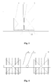
- FIG. 2 is a schematic diagram of a blower aeration system in accordance with one embodiment of the invention
- FIG. 3 is a schematic diagram of a jet aeration system in accordance with one embodiment of the invention.
- FIG. 4 is a top view of an aeration system in accordance with one embodiment of the invention.
- a method of treatment of sludge with a facultative membrane bioreactor comprising providing a sludge treatment system comprising a facultative digestion tank 9, a membrane module 4, an aeration system, a sludge pump 8, and a drainage pump 12.
- the sludge pump 8 is connected to a secondary sedimentation tank 1 via a sludge inlet pipe 7 and connected to the facultative digestion tank 9 via a sludge outlet pipe 2. Sludge is pumped into the facultative digestion tank 9 and digested therein. Pumped by the drainage pump 12, the sludge is filtrated by the membrane module 4 and thereby sludge and water are separated, and the water is drained out.
- the opening and closure of the sludge pump 8 is controlled by a ball-float level indicator 13 in the facultative digestion tank 9.
- a ball-float level indicator 13 in the facultative digestion tank 9.
- the sludge pump 8 is initiated and pumps sludge into the facultative digestion tank 9.
- An aeration pipe 5 is connected to a jet aerator 15 or a blower 18. Air or a mixture comprising sludge, water, and air is sprayed into the facultative digestion tank 9 via a plurality of aeration holes of perforated aeration tube 11.
- the perforated aeration tube 11 is disposed equidistantly right below the membrane module 4, one end thereof connected to the aeration branch pipe 10 and the other end closed.
- the aeration branch pipe 10 is connected to the aeration pipe 5 and both ends thereof are closed.
- the aeration pipe 5 is connected to the blower 18 via an air duct 17 or to the jet aerator 15 directly.
- a plurality of aeration holes are disposed at both sides of the perforated aeration tube 11, and an angle between the aeration hole and vertical line is ⁇ 45°.
- a diameter of the aeration hole is 4-10 mm.
- the perforated aeration tube 11 is disposed 300 mm below the bottom of the membrane module 4. A distance between two aeration holes is 200 mm.
- the aeration system is a blower aeration system or a jet aeration system.
- the blower aeration system comprises the blower 18, the air duct 17, and the aeration pipe 5.
- the blower 18 is connected to the aeration pipe 5 via the air duct 17.
- the jet aeration system comprises the jet aerator 15 and affiliated pipes.
- the water inlet 14 of the jet aerator 15 is disposed below the liquid surface 3 of the facultative digestion tank 9.
- the air inlet 16 is disposed above the liquid surface 3 of the facultative digestion tank 9.
- the outlet of the jet aerator 15 is connected to the aeration branch pipe 10 via the aeration pipe 5.
- sludge is treated following the steps of:
- the aeration of the membrane module 4 is implemented by the blower 18.
- the blower 18 is connected to the perforated aeration tube 11 via the air duct 17, the aeration pipe 5, and the aeration branch pipe 10. Air or a mixture comprising of sludge, water, and air is sprayed into the facultative digestion tank 9 via a plurality of aeration holes of perforated aeration tube 11 and scours the membrane module 4.
- a jet aeration system for a method of treatment of sludge.
- the method is basically similar to Embodiment 1 except that a blower 18 is substituted with a jet aerator 15.
- An aeration pipe 5 is connected to the jet aerator 15 directly.
Landscapes
- Life Sciences & Earth Sciences (AREA)
- Chemical & Material Sciences (AREA)
- Engineering & Computer Science (AREA)
- Water Supply & Treatment (AREA)
- Environmental & Geological Engineering (AREA)
- Hydrology & Water Resources (AREA)
- Organic Chemistry (AREA)
- Biodiversity & Conservation Biology (AREA)
- Microbiology (AREA)
- Chemical Kinetics & Catalysis (AREA)
- Health & Medical Sciences (AREA)
- Molecular Biology (AREA)
- General Chemical & Material Sciences (AREA)
- Oil, Petroleum & Natural Gas (AREA)
- Separation Using Semi-Permeable Membranes (AREA)
- Treatment Of Sludge (AREA)
- Activated Sludge Processes (AREA)
Abstract
Description
- The invention relates to a method for treatment of sludge, and more particularly to a method for treatment of sludge with a facultative membrane bioreactor.
- Currently, more than 50% of sewage treatment plants adopt aerobic activated sludge process to treat sewage. However, the process produces a large amount of excess sludge that has complicated components and does great harm to environment. Conventional methods for treating excess sludge mainly lie in that excess sludge is firstly dehydrated in a sewage plant and then packaged and transported for landfill, incineration, or composting and so on.
- However, these conventional methods have disadvantages as below: (1) in order to make excess sludge dehydrated and transport the dehydrated excess sludge, the overall investment of sludge treatment system is large; (2) the relevant technology and equipment required for an incineration method are complicated, high energy consuming and high cost, and causes atmospheric pollution; (3) a sludge landfill method requires a high soil mechanics properties of sludge, a large area of space and high transportation cost, additionally, the method easily cause groundwater pollution and atmospheric pollution due to landfill smell; and (4) a composting method easily causes heavy metal pollution.
- In view of the above-described problems, it is one objective of the invention to provide a method for treatment of sludge with a facultative membrane bioreactor that greatly reduces the yield of excess sludge.
- To achieve the above objectives, in accordance with one embodiment of the invention, there is provided a method for treatment of sludge with a facultative membrane bioreactor that greatly reduces the yield of excess sludge, the method comprising the steps of:
- a) providing a sludge treatment system comprising a facultative digestion tank, a membrane module, an aeration system, a sludge pump, and a drainage pump;
- b) pumping sludge into the facultative digestion tank via the sludge pump and allowing for digestion;
- c) synchronously aerating and scouring the membrane module by the aeration system;
- d) pumping the sludge by the drainage pump and filtrating by the membrane module so that sludge and water are separated; and
- e) draining the water via the drainage pump.
- In a class of this embodiment, the facultative digestion tank provides reaction conditions for facultative or anaerobic digestion of sludge, and most area of the facultative digestion tank is maintained in a facultative or anaerobic state, the average concentration of dissolved oxygen being <1.0 mg/L. Facultative microbe is predominant in the facultative digestion tank.
- The above-mentioned sludge digestion refers to the disintegration of excess sludge due to the endogenous respiration of microbe. The resultant organic compounds are completely decomposed into water, carbon dioxide, and inorganic salts in the presence of facultative or anaerobic microbe in the facultative digestion tank. The water and inorganic salts are drained out and the carbon dioxide becomes a part of the atmosphere.
- In a class of this embodiment, the facultative digestion tank is made of reinforced concrete or steel.
- In a class of this embodiment, the sludge is pumped by the sludge pump from a secondary sedimentation tank into the facultative digestion tank. An opening and closure of the sludge pump is controlled by a ball-float level indicator in the facultative digestion tank.
- In a class of this embodiment, the membrane module is micro-filtration membrane module, the amount thereof is based on the amount of daily treated sludge, and the water yield thereof is equivalent to the amount of daily treated organic excess sludge.
- In a class of this embodiment, the aeration system mainly provides air-water scouring against the membrane module so as to prevent sludge from depositing and polluting the membrane.
- In a class of this embodiment, the aeration system is a blower aeration system.
- In a class of this embodiment, the aeration system is a jet aeration system.
- In a class of this embodiment, the blower aeration system comprises a blower, an air duct, an aeration pipe, an aeration branch pipe, and a perforated aeration tube. The perforated aeration tube is disposed below the membrane module. The blower is disposed out of the facultative digestion tank and connected to the perforated aeration tube via the air duct, the aeration pipe, and the aeration branch pipe, and provides air-water scouring against the membrane module, and an air-water ratio being 10-30: 1.
- In a class of this embodiment, the jet aeration system comprises a jet aerator, an air inlet, a water inlet, an outlet, an aeration pipe, an aeration branch pipe, and a perforated aeration tube. The jet aerator is disposed between the membrane modules or at the side of the membrane module. The air inlet is disposed above the liquid surface of the facultative digestion tank. The water inlet is disposed below the liquid surface of the facultative digestion tank. The outlet is connected to the perforated aeration tube via the aeration pipe and the aeration branch pipe.
- When the jet aeration system works, a negative pressure is formed due to high speed of fluid flow in the jet aerator, and air is absorbed by the air inlet and forms a mixture having microbe with liquid and solid in the aeration pipe. The mixture is transported by the perforated aeration tube and scours against the membrane modules, and thereby a pollution of the membrane module is avoided.
- In a class of this embodiment, the perforated aeration tube is disposed equidistantly below the membrane module, and connected to the blower or jet aerator via the aeration pipe, the aeration branch pipe and/or the air duct.
- In a class of this embodiment, both ends of the aeration branch pipe are closed, and both sides are connected to the perforated aeration tube. A plurality of aeration holes is disposed on the perforated aeration tube. An angle between the aeration hole and vertical line is ±44°- 46°; a diameter of the aeration hole is 4-10 mm; and a distance between two aeration holes is 100-300 mm.
- In a class of this embodiment, the perforated aeration tube is disposed 100-500 mm below the bottom of the membrane module, and is composed of corrosion-resistant tubes.
- Advantages of the invention are summarized below: the method can digest sludge completely in the digestion tank, and solves problems existing in conventional sludge treatment methods such as large investment and high transportation cost, even achieves a subject of zero discharge of sludge.
- The invention is described hereinbelow with reference to accompanying drawings, in which:
-
FIG. 1 is a flow chart of a method of treatment of sludge in accordance with one embodiment of the invention; -
FIG. 2 is a schematic diagram of a blower aeration system in accordance with one embodiment of the invention; -
FIG. 3 is a schematic diagram of a jet aeration system in accordance with one embodiment of the invention; and -
FIG. 4 is a top view of an aeration system in accordance with one embodiment of the invention. - Labels: 1. secondary sedimentation tank; 2. sludge outlet pipe; 3. liquid surface; 4. membrane module; 5. aeration pipe; 6. water outlet pipe; 7. sludge inlet pipe; 8. sludge pump; 9. facultative digestion tank; 10. aeration branch pipe; 11. perforated aeration tube; 12. drainage pump; 13. ball-float level indicator; 14. water inlet; 15. jet aerator; 16. air inlet; 17. air duct; 18. blower.
- For further illustrating the invention, embodiments detailing a method of treatment of sludge with a facultative membrane bioreactor are described below. It should be noted that the following embodiments are intended to describe but not to limit the invention.
- Embodiment 1
- As shown in
FIGS. 1, 2 ,3, and 4 , a method of treatment of sludge with a facultative membrane bioreactor comprising providing a sludge treatment system comprising a facultative digestion tank 9, amembrane module 4, an aeration system, asludge pump 8, and adrainage pump 12. Thesludge pump 8 is connected to a secondary sedimentation tank 1 via asludge inlet pipe 7 and connected to the facultative digestion tank 9 via asludge outlet pipe 2. Sludge is pumped into the facultative digestion tank 9 and digested therein. Pumped by thedrainage pump 12, the sludge is filtrated by themembrane module 4 and thereby sludge and water are separated, and the water is drained out. The opening and closure of thesludge pump 8 is controlled by a ball-float level indicator 13 in the facultative digestion tank 9. When the liquid surface 3 of the facultative digestion tank 9 is lower than a set value, thesludge pump 8 is initiated and pumps sludge into the facultative digestion tank 9. Anaeration pipe 5 is connected to ajet aerator 15 or a blower 18. Air or a mixture comprising sludge, water, and air is sprayed into the facultative digestion tank 9 via a plurality of aeration holes ofperforated aeration tube 11. - The
perforated aeration tube 11 is disposed equidistantly right below themembrane module 4, one end thereof connected to theaeration branch pipe 10 and the other end closed. Theaeration branch pipe 10 is connected to theaeration pipe 5 and both ends thereof are closed. Theaeration pipe 5 is connected to the blower 18 via anair duct 17 or to thejet aerator 15 directly. A plurality of aeration holes are disposed at both sides of the perforatedaeration tube 11, and an angle between the aeration hole and vertical line is ±45°. A diameter of the aeration hole is 4-10 mm. Theperforated aeration tube 11 is disposed 300 mm below the bottom of themembrane module 4. A distance between two aeration holes is 200 mm. - The aeration system is a blower aeration system or a jet aeration system.
- The blower aeration system comprises the blower 18, the
air duct 17, and theaeration pipe 5. The blower 18 is connected to theaeration pipe 5 via theair duct 17. - The jet aeration system comprises the
jet aerator 15 and affiliated pipes. Thewater inlet 14 of thejet aerator 15 is disposed below the liquid surface 3 of the facultative digestion tank 9. Theair inlet 16 is disposed above the liquid surface 3 of the facultative digestion tank 9. The outlet of thejet aerator 15 is connected to theaeration branch pipe 10 via theaeration pipe 5. - In this embodiment, sludge is treated following the steps of:
- a) pumping the sludge from the secondary sedimentation tank 1 into the facultative digestion tank 9 via the
sludge inlet pipe 7, thesludge pump 8, and thesludge outlet pipe 2, and allowing for digestion; - b) synchronously aerating and scouring the
membrane module 4 by the blower aeration system; - c) pumping the sludge by the
drainage pump 12 and filtrating by themembrane module 4 so that sludge and water are separated; and - d) draining the water via the
drainage pump 12. - In this embodiment, the aeration of the
membrane module 4 is implemented by the blower 18. The blower 18 is connected to theperforated aeration tube 11 via theair duct 17, theaeration pipe 5, and theaeration branch pipe 10. Air or a mixture comprising of sludge, water, and air is sprayed into the facultative digestion tank 9 via a plurality of aeration holes ofperforated aeration tube 11 and scours themembrane module 4. -
Embodiment 2 - As shown in
FIG. 3 , a jet aeration system for a method of treatment of sludge. The method is basically similar to Embodiment 1 except that a blower 18 is substituted with ajet aerator 15. Anaeration pipe 5 is connected to thejet aerator 15 directly. - While particular embodiments of the invention have been shown and described, it will be obvious to those skilled in the art that changes and modifications may be made without departing from the invention in its broader aspects, and therefore, the aim in the appended claims is to cover all such changes and modifications as fall within the true spirit and scope of the invention.
Claims (15)
- A method for treatment of sludge, comprisinga) providing a sludge treatment system comprising a facultative digestion tank, a membrane module, an aeration system, a sludge pump, and a drainage pump;b) pumping sludge into said facultative digestion tank via said sludge pump and allowing for digestion;c) synchronously aerating and scouring said membrane module by said aeration system;d) pumping said sludge by said drainage pump and filtrating by said membrane module so that said sludge and water are separated; ande) draining said water via said drainage pump.
- The method of claim 1, wherein an opening and closure of said sludge pump is controlled by a ball-float level indicator in said facultative digestion tank.
- The method of claim 1, wherein most area of said facultative digestion tank is maintained in a facultative or anaerobic state, the average concentration of dissolved oxygen being <1.0 mg/L.
- The method of claim 1, wherein facultative microbe is predominant in said facultative digestion tank.
- The method of claim 1, wherein said facultative digestion tank is made of reinforced concrete or steel.
- The method of claim 1, wherein said membrane module is a micro-filtration membrane module, the amount thereof is based on the amount of daily treated sludge, and the water yield thereof is equivalent to the amount of daily treated organic excess sludge.
- The method of claim 1, wherein said aeration system is a blower aeration system and provides air-water scouring against said membrane module.
- The method of claim 1, wherein said aeration system is a jet aeration system and provides air-water scouring against said membrane module.
- The method of claim 7, wherein said blower aeration system comprises a blower, an air duct, an aeration pipe, an aeration branch pipe, and a perforated aeration tube, said perforated aeration tube being disposed below said membrane module, said blower being disposed out of said facultative digestion tank and being connected to said perforated aeration tube via said air duct, and providing air-water scouring against said membrane module, and an air-water ratio being 10-30: 1.
- The method of claim 7, wherein said perforated aeration tube is disposed equidistantly below said membrane module, and connected to said blower via said aeration branch pipe, said aeration pipe, and said air duct.
- The method of claim 7, wherein one end of said perforated aeration tube is connected to said aeration branch pipe, the other end is closed; a plurality of aeration holes is disposed at both sides of said perforated aeration tube, and an angle between said aeration hole and vertical line is ±44°- 46°; a diameter of said aeration hole is 4-10 mm; and a distance between two aeration holes is 100-300 mm.
- The method of claim 8, wherein said jet aeration system comprises a jet aerator, an air inlet, a water inlet, an outlet, an aeration pipe, an aeration branch pipe, and a perforated aeration tube;
said jet aerator is disposed between said membrane modules or at the side of said membrane module;
said air inlet is disposed above the liquid surface of said facultative digestion tank;
said water inlet is disposed below the liquid surface of said facultative digestion tank; and
said outlet is connected to said perforated aeration tube via said aeration pipe and said aeration branch pipe. - The method of claim 12, wherein when said jet aeration system works, a negative pressure is formed due to high speed of fluid flow in said jet aerator, air is absorbed by said air inlet and forms a mixture having microbe with liquid and solid in said aeration pipe, said mixture is transported by said perforated aeration tube and scours against said membrane modules, and thereby a pollution of said membrane module is avoided.
- The method of claim 12, wherein said perforated aeration tube is disposed equidistantly below said membrane module, and connected to said jet aerator via said aeration branch pipe.
- The method of claim 12, wherein one end of said perforated aeration tube is connected to said aeration branch pipe, the other end is closed; a plurality of aeration holes is disposed at both sides of said perforated aeration tube, and an angle between said aeration hole and vertical line is ±44°- 46°; a diameter of said aeration hole is 4-10 mm; and a distance between two aeration holes is 100-300 mm.
Applications Claiming Priority (1)
| Application Number | Priority Date | Filing Date | Title |
|---|---|---|---|
| CN2009101153516A CN101885570B (en) | 2009-05-15 | 2009-05-15 | Sludge treatment method |
Publications (1)
| Publication Number | Publication Date |
|---|---|
| EP2251307A1 true EP2251307A1 (en) | 2010-11-17 |
Family
ID=42016957
Family Applications (1)
| Application Number | Title | Priority Date | Filing Date |
|---|---|---|---|
| EP20090181031 Ceased EP2251307A1 (en) | 2009-05-15 | 2009-12-30 | Method for treatment of sludge |
Country Status (4)
| Country | Link |
|---|---|
| US (1) | US8262911B2 (en) |
| EP (1) | EP2251307A1 (en) |
| JP (1) | JP5596949B2 (en) |
| CN (1) | CN101885570B (en) |
Cited By (6)
| Publication number | Priority date | Publication date | Assignee | Title |
|---|---|---|---|---|
| CN102060418A (en) * | 2010-12-08 | 2011-05-18 | 沈阳大学 | Empty Tower Aeration Ecological Filter Bed Sewage Treatment System |
| CN102674539A (en) * | 2012-05-09 | 2012-09-19 | 浙江清华长三角研究院 | Nitrified sludge efficient enriching culture system based on membrane bioreactor and method |
| WO2017035892A1 (en) * | 2015-09-01 | 2017-03-09 | Jiangxi Jdl Environmental Protection Co., Ltd. | Method and system for wastewater treatment using membrane bioreactor |
| CN106517498A (en) * | 2016-12-30 | 2017-03-22 | 中冶华天工程技术有限公司 | Dynamic bottom aeration system and aeration method thereof |
| EP3344584A4 (en) * | 2015-09-01 | 2018-07-11 | Jiangxi JDL Environmental Protection Co., Ltd. | Method and system of wastewater treatment with zero discharge of sludge |
| CN117263369A (en) * | 2023-11-22 | 2023-12-22 | 水研未来(北京)环境工程技术有限公司 | Diaphragm gas-water mixing continuous cleaning device and cleaning method in membrane bioreactor |
Families Citing this family (18)
| Publication number | Priority date | Publication date | Assignee | Title |
|---|---|---|---|---|
| CN101830555B (en) * | 2009-03-09 | 2011-12-28 | 江西金达莱环保研发中心有限公司 | Jet aeration device and jet aeration method thereof |
| CN101885539B (en) * | 2009-05-15 | 2012-06-20 | 江西金达莱环保研发中心有限公司 | Facultative aerobic membrane bioreactor process |
| JP5439344B2 (en) * | 2010-11-16 | 2014-03-12 | 株式会社東芝 | Membrane separation biological treatment equipment |
| US20130015130A1 (en) * | 2011-07-13 | 2013-01-17 | Joseph Breitner | Pulse aeration for immersed membranes |
| CN102491731B (en) * | 2011-12-08 | 2013-07-31 | 复旦大学 | Preparation method of biological ceramsite |
| US9463419B2 (en) | 2012-01-09 | 2016-10-11 | General Electric Company | Pulse aeration for immersed membranes |
| CN102730914B (en) * | 2012-07-12 | 2014-04-02 | 江西金达莱环保股份有限公司 | Method for processing livestock breeding wastewater by using anoxic membrane bioreactor |
| US20160185634A1 (en) * | 2013-08-08 | 2016-06-30 | Lotte Chemical Corporation | Air diffuser and membrane bio-reactor |
| CN103539251A (en) * | 2013-10-22 | 2014-01-29 | 江西金达莱环保股份有限公司 | Method for synchronously degrading carbon, nitrogen and phosphorus in wastewater without discharging sludge |
| AU2015337112A1 (en) | 2014-10-22 | 2017-05-18 | Koch Membrane Systems, Inc. | Membrane module system with bundle enclosures and pulsed aeration and method of operation |
| USD779631S1 (en) | 2015-08-10 | 2017-02-21 | Koch Membrane Systems, Inc. | Gasification device |
| CN105923767A (en) * | 2015-09-01 | 2016-09-07 | 江西金达莱环保股份有限公司 | Facultative anaerobic membrane bioreactor process and wastewater treatment system |
| CN105923749A (en) * | 2015-09-01 | 2016-09-07 | 江西金达莱环保股份有限公司 | Gasification dephosphorization sewage treatment method and system |
| CN109205937A (en) * | 2018-09-29 | 2019-01-15 | 山东天水务工程有限公司 | Biochemical sludge zero-emission sewage treatment process |
| CN109607848A (en) * | 2018-11-23 | 2019-04-12 | 临猗县鑫得利纺织印染有限公司 | Wetland waste water reuse system |
| CN109455813A (en) * | 2018-12-28 | 2019-03-12 | 肇庆市鹏凯环保装备有限公司 | A kind of reaction unit with metazoa decrement excess sludge |
| CN112191105A (en) * | 2020-09-08 | 2021-01-08 | 重庆耐德环境技术有限公司 | Low-consumption membrane module flushing system |
| CN112429845A (en) * | 2020-11-17 | 2021-03-02 | 光大水务(深圳)有限公司 | Method and device for aerobic biochemical treatment of sewage easy to foam |
Citations (7)
| Publication number | Priority date | Publication date | Assignee | Title |
|---|---|---|---|---|
| EP0970922A2 (en) * | 1998-07-06 | 2000-01-12 | Kubota Corporation | Method for methane fermentation of organic waste |
| DE10004863A1 (en) * | 1999-08-04 | 2001-02-15 | Wehrle Werk Ag | Separation of solids and liquid from sludge suspension using high efficiency, low cost agitated filter, passes flow of suspended air bubbles tangentially and turbulently past loosely-held filter membrane |
| EP1346956A1 (en) * | 2002-03-15 | 2003-09-24 | Genix Engineering, Inc. | Process for sludge treatment using sludge pretreatment and membrane bioreactor |
| US20040112831A1 (en) * | 1998-10-09 | 2004-06-17 | Rabie Hamid R. | Cyclic aeration system for submerged membrane modules |
| US20050109694A1 (en) * | 2003-11-21 | 2005-05-26 | Industrial Technology Research Institute | Method and system for treating wastewater containing organic compounds |
| US20070209998A1 (en) * | 2006-03-07 | 2007-09-13 | Siemens Water Technologies Corp. | Multivalent Metal Ion Management for Low Sludge Processes |
| WO2008024445A2 (en) * | 2006-08-23 | 2008-02-28 | Siemens Water Technologies Corp. | Sequencing batch reactor with continuous membrane filtration and solids reduction |
Family Cites Families (32)
| Publication number | Priority date | Publication date | Assignee | Title |
|---|---|---|---|---|
| US3807700A (en) * | 1972-07-05 | 1974-04-30 | S Kennedy | Mixing apparatus for forming a slurry |
| WO1986005771A1 (en) * | 1985-04-01 | 1986-10-09 | Mitsui Sekiyu Kagaku Kogyo Kabushiki Kaisha | Method of treating active sludge in waste water |
| JPH0720599B2 (en) * | 1990-08-28 | 1995-03-08 | 株式会社クボタ | Intermittent aeration type activated sludge treatment method |
| JPH04290590A (en) * | 1991-03-19 | 1992-10-15 | Kubota Corp | Membrane separator in septic tank |
| JPH05185092A (en) * | 1992-01-10 | 1993-07-27 | Kubota Corp | Waste water disposing device |
| JP3167242B2 (en) * | 1994-03-24 | 2001-05-21 | 株式会社クボタ | Septic tank combined with membrane separation |
| JP3368682B2 (en) * | 1994-09-14 | 2003-01-20 | 東陶機器株式会社 | Septic tank and its operation method |
| JPH1085565A (en) * | 1996-09-19 | 1998-04-07 | Yamada Kogyo Kk | Membrane separator |
| JPH10305292A (en) * | 1997-05-06 | 1998-11-17 | Nittetsu Kakoki Kk | Waste water purifying equipment |
| JPH11179398A (en) * | 1997-12-24 | 1999-07-06 | Mitsubishi Rayon Co Ltd | Activated sludge treatment equipment |
| JP3442288B2 (en) * | 1998-07-06 | 2003-09-02 | 株式会社クボタ | Methane fermentation method for organic waste |
| JP2000061273A (en) * | 1998-08-25 | 2000-02-29 | Sumitomo Heavy Ind Ltd | Membrane separator and its membrane cleaning method |
| US6616843B1 (en) * | 1998-12-18 | 2003-09-09 | Omnium De Traitement Et De Valorisation | Submerged membrane bioreactor for treatment of nitrogen containing water |
| JP2000288575A (en) * | 1999-04-07 | 2000-10-17 | Ishikawajima Harima Heavy Ind Co Ltd | Wastewater treatment method and apparatus |
| US6361695B1 (en) * | 1999-10-02 | 2002-03-26 | Zenon Environmental Inc. | Shipboard wastewater treatment system |
| JP3836038B2 (en) * | 2002-03-12 | 2006-10-18 | 株式会社クボタ | Sludge treatment method and treatment equipment |
| US6984325B1 (en) * | 2002-04-09 | 2006-01-10 | Venable Robert T | Water and aqueous mix treatment using venturi discharge oxygen |
| FR2843106B1 (en) * | 2002-08-05 | 2004-10-08 | Omnium Traitement Valorisa | PROCESS AND PLANT FOR TREATING SLUDGE FROM BIOLOGICAL WATER PURIFICATION PLANTS |
| JP2004230349A (en) * | 2003-01-31 | 2004-08-19 | Toshiba Plant Systems & Services Corp | Wastewater treatment equipment |
| JP4361743B2 (en) * | 2003-02-21 | 2009-11-11 | 三菱レイヨン株式会社 | Wastewater treatment method |
| JP4059790B2 (en) * | 2003-02-28 | 2008-03-12 | 義公 渡辺 | Membrane separation activated sludge treatment apparatus and membrane separation activated sludge treatment method |
| CN1245337C (en) * | 2003-07-30 | 2006-03-15 | 财团法人工业技术研究院 | Biological sludge reduction equipment |
| CN1281522C (en) * | 2003-11-24 | 2006-10-25 | 财团法人工业技术研究院 | Wastewater treatment system containing organic pollutants and treatment method thereof |
| WO2005107929A2 (en) * | 2004-04-22 | 2005-11-17 | Siemens Water Technologies Corp. | Filtration apparatus comprising a membrane bioreactor and a treatment vessel for digesting organic materials |
| US7396453B1 (en) * | 2005-04-19 | 2008-07-08 | Procorp Enterprises, Llc | Hydraulically integrated solids/liquid separation system for wastewater treatment |
| JP4250163B2 (en) * | 2005-09-16 | 2009-04-08 | シャープ株式会社 | Water treatment method and water treatment apparatus |
| JP2007136389A (en) * | 2005-11-21 | 2007-06-07 | Ngk Insulators Ltd | Aeration device |
| US7510655B2 (en) * | 2006-04-11 | 2009-03-31 | Siemens Water Technologies Corp. | Process to improve the efficiency of a membrane filter activated sludge system |
| JP2008238042A (en) * | 2007-03-27 | 2008-10-09 | Unitika Ltd | Reduction method of organic sludge |
| JPWO2009047970A1 (en) * | 2007-10-10 | 2011-02-17 | 東レ株式会社 | Fine bubble diffuser, fine bubble diffuser, and submerged membrane separator |
| CN101830555B (en) * | 2009-03-09 | 2011-12-28 | 江西金达莱环保研发中心有限公司 | Jet aeration device and jet aeration method thereof |
| CN101885539B (en) * | 2009-05-15 | 2012-06-20 | 江西金达莱环保研发中心有限公司 | Facultative aerobic membrane bioreactor process |
-
2009
- 2009-05-15 CN CN2009101153516A patent/CN101885570B/en active Active
- 2009-09-02 US US12/552,558 patent/US8262911B2/en active Active
- 2009-09-22 JP JP2009218261A patent/JP5596949B2/en active Active
- 2009-12-30 EP EP20090181031 patent/EP2251307A1/en not_active Ceased
Patent Citations (7)
| Publication number | Priority date | Publication date | Assignee | Title |
|---|---|---|---|---|
| EP0970922A2 (en) * | 1998-07-06 | 2000-01-12 | Kubota Corporation | Method for methane fermentation of organic waste |
| US20040112831A1 (en) * | 1998-10-09 | 2004-06-17 | Rabie Hamid R. | Cyclic aeration system for submerged membrane modules |
| DE10004863A1 (en) * | 1999-08-04 | 2001-02-15 | Wehrle Werk Ag | Separation of solids and liquid from sludge suspension using high efficiency, low cost agitated filter, passes flow of suspended air bubbles tangentially and turbulently past loosely-held filter membrane |
| EP1346956A1 (en) * | 2002-03-15 | 2003-09-24 | Genix Engineering, Inc. | Process for sludge treatment using sludge pretreatment and membrane bioreactor |
| US20050109694A1 (en) * | 2003-11-21 | 2005-05-26 | Industrial Technology Research Institute | Method and system for treating wastewater containing organic compounds |
| US20070209998A1 (en) * | 2006-03-07 | 2007-09-13 | Siemens Water Technologies Corp. | Multivalent Metal Ion Management for Low Sludge Processes |
| WO2008024445A2 (en) * | 2006-08-23 | 2008-02-28 | Siemens Water Technologies Corp. | Sequencing batch reactor with continuous membrane filtration and solids reduction |
Non-Patent Citations (1)
| Title |
|---|
| "VARI-CANT Jet Aeration Systems Superior Technology in Wastewater Treatment", 19 June 2008 (2008-06-19), XP055158304, Retrieved from the Internet <URL:http://www.sawea.org/pdf/2009/Industrial WW Workshop/Food Industry Wastewater Treatment/Brochures/Biological Treatment/Jet Aeration.pdf> [retrieved on 20141212] * |
Cited By (8)
| Publication number | Priority date | Publication date | Assignee | Title |
|---|---|---|---|---|
| CN102060418A (en) * | 2010-12-08 | 2011-05-18 | 沈阳大学 | Empty Tower Aeration Ecological Filter Bed Sewage Treatment System |
| CN102674539A (en) * | 2012-05-09 | 2012-09-19 | 浙江清华长三角研究院 | Nitrified sludge efficient enriching culture system based on membrane bioreactor and method |
| WO2017035892A1 (en) * | 2015-09-01 | 2017-03-09 | Jiangxi Jdl Environmental Protection Co., Ltd. | Method and system for wastewater treatment using membrane bioreactor |
| EP3344584A4 (en) * | 2015-09-01 | 2018-07-11 | Jiangxi JDL Environmental Protection Co., Ltd. | Method and system of wastewater treatment with zero discharge of sludge |
| EP3344587A4 (en) * | 2015-09-01 | 2018-08-22 | Jiangxi JDL Environmental Protection Co., Ltd. | Method and system for wastewater treatment using membrane bioreactor |
| CN106517498A (en) * | 2016-12-30 | 2017-03-22 | 中冶华天工程技术有限公司 | Dynamic bottom aeration system and aeration method thereof |
| CN117263369A (en) * | 2023-11-22 | 2023-12-22 | 水研未来(北京)环境工程技术有限公司 | Diaphragm gas-water mixing continuous cleaning device and cleaning method in membrane bioreactor |
| CN117263369B (en) * | 2023-11-22 | 2024-02-27 | 水研未来(北京)环境工程技术有限公司 | Diaphragm gas-water mixing continuous cleaning device and cleaning method in membrane bioreactor |
Also Published As
| Publication number | Publication date |
|---|---|
| CN101885570A (en) | 2010-11-17 |
| US8262911B2 (en) | 2012-09-11 |
| CN101885570B (en) | 2012-04-04 |
| JP5596949B2 (en) | 2014-09-24 |
| JP2010264436A (en) | 2010-11-25 |
| US20100288696A1 (en) | 2010-11-18 |
Similar Documents
| Publication | Publication Date | Title |
|---|---|---|
| US8262911B2 (en) | Method for treatment of sludge | |
| CN105439389B (en) | A kind of landfill leachate zero-discharge treatment system | |
| CN101250006B (en) | Aerobic-anaerobic cycling treatment fluidized bed reactor for landfill leachate | |
| CN110980927A (en) | Black and odorous river regulation device and process based on bubble-free oxygenation technology | |
| CN100540487C (en) | Integrated high concentration refractory sewage treatment device | |
| CN201136823Y (en) | An aerobic anaerobic cycle treatment device for waste water | |
| CN106477802B (en) | high-concentration organic wastewater treatment system | |
| CN216005329U (en) | Pioneer bioreactor for treating organic high-concentration wastewater | |
| CN104150680A (en) | Treatment method and system for electroplating wastewater | |
| US7566397B2 (en) | Superoxygenation of raw wastewater for odor/corrosion control | |
| CN206927755U (en) | Integrated sewage treating apparatus | |
| CN104829039A (en) | Efficient combination type domestic sewage treatment apparatus | |
| CN201506745U (en) | Water-based ink sewage purification device | |
| CN111960618A (en) | Overlapping and splicing sewage treatment equipment and method for coastal region quasi-IV water | |
| CN104926019A (en) | Treatment system for high-carbon-and-nitrogen wastewater | |
| CN205528260U (en) | Sewage treatment system | |
| CN208717099U (en) | A three-dimensional integrated sewage treatment equipment | |
| CN204874185U (en) | High salt sewage treatment plant | |
| CN204897658U (en) | Integral, sewage treatment equipment | |
| CN213037624U (en) | Double-system full-automatic integrated sewage treatment equipment | |
| CN222274292U (en) | An integrated modular sewage treatment equipment | |
| CN115710064A (en) | Anaerobic MBR (membrane bioreactor) treatment system and treatment method for domestic sewage | |
| CN210393863U (en) | Aquaculture wastewater ozone treatment equipment | |
| CN203754561U (en) | Leachate treatment device | |
| CN210481143U (en) | A sewage treatment system based on MBR membrane technology |
Legal Events
| Date | Code | Title | Description |
|---|---|---|---|
| PUAI | Public reference made under article 153(3) epc to a published international application that has entered the european phase |
Free format text: ORIGINAL CODE: 0009012 |
|
| AK | Designated contracting states |
Kind code of ref document: A1 Designated state(s): AT BE BG CH CY CZ DE DK EE ES FI FR GB GR HR HU IE IS IT LI LT LU LV MC MK MT NL NO PL PT RO SE SI SK SM TR |
|
| AX | Request for extension of the european patent |
Extension state: AL BA RS |
|
| 17P | Request for examination filed |
Effective date: 20110423 |
|
| 17Q | First examination report despatched |
Effective date: 20110601 |
|
| RAP1 | Party data changed (applicant data changed or rights of an application transferred) |
Owner name: JIANGXI JDL ENVIRONMENTAL PROTECTION RESEARCH LTD. |
|
| RAP1 | Party data changed (applicant data changed or rights of an application transferred) |
Owner name: JIANGXI JDL ENVIRONMENTAL PROTECTION CO., LTD. |
|
| STAA | Information on the status of an ep patent application or granted ep patent |
Free format text: STATUS: THE APPLICATION HAS BEEN REFUSED |
|
| 18R | Application refused |
Effective date: 20150127 |