EP2251258A2 - Aircraft high-lift system and method for determining the operational state of same - Google Patents
Aircraft high-lift system and method for determining the operational state of same Download PDFInfo
- Publication number
- EP2251258A2 EP2251258A2 EP10004888A EP10004888A EP2251258A2 EP 2251258 A2 EP2251258 A2 EP 2251258A2 EP 10004888 A EP10004888 A EP 10004888A EP 10004888 A EP10004888 A EP 10004888A EP 2251258 A2 EP2251258 A2 EP 2251258A2
- Authority
- EP
- European Patent Office
- Prior art keywords
- load
- flap
- aircraft
- station
- torque
- Prior art date
- Legal status (The legal status is an assumption and is not a legal conclusion. Google has not performed a legal analysis and makes no representation as to the accuracy of the status listed.)
- Granted
Links
- 238000000034 method Methods 0.000 title claims abstract description 14
- 230000005540 biological transmission Effects 0.000 claims abstract description 90
- 238000001514 detection method Methods 0.000 claims abstract description 25
- 238000011156 evaluation Methods 0.000 claims description 37
- 238000012544 monitoring process Methods 0.000 claims description 10
- 230000033001 locomotion Effects 0.000 claims description 8
- 238000004891 communication Methods 0.000 claims description 5
- 238000012546 transfer Methods 0.000 claims description 4
- 230000004913 activation Effects 0.000 abstract 1
- 238000010276 construction Methods 0.000 description 4
- 230000004807 localization Effects 0.000 description 4
- 238000012423 maintenance Methods 0.000 description 4
- 230000004044 response Effects 0.000 description 3
- 230000000694 effects Effects 0.000 description 2
- 241001295925 Gegenes Species 0.000 description 1
- 238000013461 design Methods 0.000 description 1
- 210000004072 lung Anatomy 0.000 description 1
- 238000011179 visual inspection Methods 0.000 description 1
Images


Classifications
-
- B—PERFORMING OPERATIONS; TRANSPORTING
- B64—AIRCRAFT; AVIATION; COSMONAUTICS
- B64D—EQUIPMENT FOR FITTING IN OR TO AIRCRAFT; FLIGHT SUITS; PARACHUTES; ARRANGEMENT OR MOUNTING OF POWER PLANTS OR PROPULSION TRANSMISSIONS IN AIRCRAFT
- B64D45/00—Aircraft indicators or protectors not otherwise provided for
- B64D45/0005—Devices specially adapted to indicate the position of a movable element of the aircraft, e.g. landing gear
- B64D2045/001—Devices specially adapted to indicate the position of a movable element of the aircraft, e.g. landing gear for indicating symmetry of flaps deflection
Definitions
- the present invention relates to an aircraft high-lift system having at least one load station for controlling a flap of a wing, preferably a landing flap and / or a luffing flap, at least one transmission with transmission sections, which are located between branch transmissions, wherein branching off the transmission to the load station by means of the branch transmission and a method for determining an operating state of an aircraft lift-up system.
- Aircraft lift systems that actuate and move wing flaps such as flaps and wing flaps of the aircraft may experience inadmissible operating conditions or fault conditions. For safety reasons, it is necessary to recognize these impermissible operating states as promptly as possible and preferably forward them directly to the pilot.
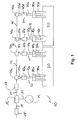
- FIG. 1 Prior art aircraft lift systems known in the art, as shown schematically in FIG. 1 shown, for example, to avoid excessive loads in the case of clamping ("jam") mechanical torque limiter 18 a.
- jam clamping
- An aircraft over-lift system with an overload safety device which comprises a drive system and elements for transmitting the drive energy over the entire span to drive stations of individual segments of landing flaps / luffing flap systems.
- the overload protection consists of at the output of the respective drive station or the control gear for the landing flaps or slats arranged force sensors such as strain gauges and / or load cells.
- force sensors such as strain gauges and / or load cells.
- the US 2006/0060719 A1 relates to an aircraft high lift system with a drive unit, elements for transmitting the drive energy to drive stations of individual segments of flaps / luffing flap systems and with an overload protection, the overload protection has at least one electrical overload sensor, which is arranged in the drive train between the drive unit and a power take-off station.
- an aircraft high-lift system has at least one load station for controlling a wing flap, preferably a landing flap and / or a louver flap, and at least one transmission with transmission sections, which are located between branch transmissions, wherein by means of the branch gear shift energy from the transmission to the load station is branchable.
- At least one detection means is provided by means of which an operating state of the transmission and / or the load station can be indirectly and / or directly determined, the detection means being arranged on the output side of the branch transmission in the input of the load station and / or in a transmission section.
- the detection means can be provided that by means of the detection means, the applied torque and / or the time profile of the torque can be detected and / or that the detection means is a torque sensor.
- the detection means is a torque sensor.
- an evaluation unit which is in signal communication with the at least one detection means and by means of which the signals of the detection means are evaluable to determine an operating condition.
- reference values and / or curves or patterns are correct operating states and faulty operating states are stored in the evaluation unit or retrievable by the evaluation unit.
- the evaluation unit logs its determination results and stores them in a memory.
- the evaluation unit can transmit the current operating states to the pilot and, if appropriate, also issue warnings in the case of faulty operating states via an output unit such as a monitor or a control instrument in the cockpit.
- the evaluation unit is a central evaluation unit, which is in signal communication with all detection means of the aircraft high-lift system.
- the information from the detection means of the left and the right wing can be evaluated jointly in the central evaluation unit.
- a load station has a station actuator and a spindle with a spindle nut, wherein the station actuator transmits the adjusting torque to the spindle and translates and the spindle nut converts the rotational movement into a translational movement for the flap, and that the detection means in the load station is arranged in front of the station actuator.
- the transmission section is a transmission section between the branch transmissions of two load stations associated with a flap.
- the torque applied there and / or the time profile of the torque can be determined by means of the detection means arranged in this transmission section.
- faulty operating states can be determined by means of the evaluation unit based on the monitoring of the ratio of the load components of the load stations and / or that based on the monitoring and the pairwise comparison of the adjoining actuating forces at the load stations of faulty operating conditions by means of the evaluation unit can be determined on the left and right wings of the aircraft and / or that a setpoint value for the adjoining control force at the load stations can be determined by means of the evaluation unit including the current values for wing configuration, aircraft weight, airspeed and / or temperature in that erroneous operating states can be determined by means of the evaluation unit on the basis of a comparison of the determined actual values with the calculated nominal values.
- the present invention relates to a method for determining an operating state of an aircraft high-lift system with the features of claim 11. Thereafter, it is provided that in a method for determining an operating state of an aircraft high-lift system with at least one load station for controlling a wing flap, preferably landing flap and / or louver flap , and at least one transmission for transmitting power to the load stations on the basis of the present at the transmission and / or in the load station torque and / or the time course of the torque indirectly and / or directly determines the operating state of the aircraft high-lift system.
- erroneous operating states are determined based on the monitoring of the ratio of the load components of the load stations.
- FIG. 1 shows a known aircraft lift-up system 10 in a schematic representation.
- the aircraft high-lift system 10 has a central drive unit 12, by means of which electrical or hydraulic energy of the aircraft supply is converted into mechanical position energy.
- brake means By means not shown brake means, the aircraft high-lift system can be kept in position.
- the central drive unit 12 transmits, via a central shaft 14, the point energy from the central drive unit 12 to a transfer case 16, which distributes the point energy to the transmission 17 of the right-hand wing and the transmission 17 'of the left-hand wing.
- the construction of the aircraft lift-up system is in the FIG. 1 shown embodiment shown substantially only for the right wing.
- each have a torque limiter 18, 18 ' is provided which blocks the drive in case of overload and the adjusting torque in the supporting structure, not shown, in particular in support structure of the transmission 17 in the fuselage and / or wing derives.
- branching 40a, 40b, 40c, 40d are arranged in the transmission, which are preferably identical.
- the branch gears 40a and 40b of the right inner landing flap 20 and the branch gears 40c and 40d of the right outer landing flap 30 are assigned.
- Each landing flap 20 and 30 are each associated with two essentially preferably constructed identical load stations 22, 24, 32, 34. More specifically, the load stations 22 and 24 are associated with the inner right landing flap 20 and the load stations 32 and 34 are associated with the right outer landing flap 30.
- the branching gear 40a, 40b, 40c, 40d take the transmission 17, the respective required job energy for the respective branching gear 40a, 40b, 40c, 40d associated load station 22, 24, 32, 34th
- first transmission section 42 Between the branch transmissions 40a and 40b there is a first transmission section 42, between the branch transmissions 40b and 40c there is a second transmission section 44 and between branch transmissions 40c and 40d there is a third transmission section 46.
- the first and third transmission sections 42 and 46 are sections the transmission 17, which lie between the branch gears 40a and 40b and 40c and 40d, which are each associated with a landing flap 20, 30.
- the transmission sections 42, 44, 46 of the transmission 17 are preferably decoupled and designed in such a way, in particular for safety reasons, that each load station 22, 24, 32, 34 can be supplied with point energy independently of the state of the other load stations.
- a station torque limiter 50a, 50b, 50c, 50d is provided, which limits the transmitted actuating torque in the event of a fault and can thus prevent damage to the load station.
- a station actuator 60a, 60b, 60c, 60d is provided, which translates the actuating torque and transmits it to the spindle 70a, 70b, 70c, 70d.
- the spindle 70a, 70b, 70c, 70d transmits the locating energy to the spindle nut 80a, 80b, 80c, 80d, which in turn converts the rotational movement imparted thereto into a translational motion. Via the guide gear 90a, 90b, 90c, 90d, this translational movement or the job energy transmitted thereby each passed to the flaps 20 and 30 and determines the kinematic course of the flap movement.
- FIG. 1 Mistake.
- FIG. 2 are each the output side of the branch gear 40a, 40b, 40c, 40d and before the station actuators 60a, 60b, 60c, 60d or gears 60a, 60b, 60c, 60d at the input shaft of the respective load station 22, 24, 32, 34 as load sensors or Torque sensors 110a, 110b, 110c, 110d executed detection means 110a, 110b, 110c, 110d arranged.
- the applied torque and thus also the actual torque curve can be detected.
- Corresponding signals are forwarded via the signal lines 102 to the electronic evaluation unit 100. To the left wing, not shown lead signal lines 102 '.
- load sensors 110 'and 110 are provided, which are in signal communication via signal lines 102 to the evaluation unit 100.
- the load sensor 110 'assigned to the inner right flap 20 is arranged on the transmission shaft 42 or the transmission section 42 between the load stations 22 and 24, while that of the outer right flap 30 is assigned Load sensor 110 "on the transmission shaft 46 and the transmission section 46 between the load stations 32 and 34 is arranged.
- the fault location is also detected by the sensors 110a, 110b, 110c, 110d or 110 ', 110 "and the signal transmitted by them, thus avoiding a time-consuming search by the maintenance personnel.
- a terminal case in the transmission 17 can be detected, for example, by overload protection devices not shown in which z. B. sensors monitor the voltage applied in the transmission torque.
- the wind loads on the flaps 20, 30 of the right and left wing are the same size. Since the drive systems of the flaps 20, 30 are axisymmetric to the aircraft longitudinal axis, the same positions also occur at the load stations on the left and right at the same positions, which are detected by the load sensors and compared in pairs in an electronic evaluation unit. On the basis of these criteria can be additionally detected by the evaluation unit 100, whether an interruption of the load path of a drive station or load station 22, 24, 32, 34, an interruption in the transmission 17, 17 'terminals of elements of the load path of a drive station, a terminals in the transmission 17, 17 'and / or a misalignment of a flap body 20, 30 is present.
- a desired value for each load station 22, 24, 32, 34 is calculated by means of the evaluation unit 100 and compared with the measured actual value. For significant deviations z. B. are detectable by means of appropriate limits, one of the error cases described above is detected. In this case, one or more limit values are assigned to each fault case, in the event of which an error case is unambiguously detected by the evaluation unit if it is exceeded or fallen short of.
- the construction of the left-hand part of the aircraft lift-up lifting system 10 according to the invention is essentially identical in construction, as in FIGS Figures 2 and 3 shown. In principle, however, is also conceivable to provide for the left and the right wing independent aircraft lift systems 10, as shown in the Figures 2 or 3 are shown.
Landscapes
- Engineering & Computer Science (AREA)
- Aviation & Aerospace Engineering (AREA)
- Retarders (AREA)
- Transmission Devices (AREA)
Abstract
Description
Die vorliegende Erfindung betrifft ein Flugzeughochauftriebssystem mit wenigstens einer Laststation zur Ansteuerung einer Klappe eines Flügels, vorzugsweise einer Landeklappe und/oder einer Vorflügelklappe, wenigstens einer Transmission mit Transmissionsabschnitten, die sich zwischen Abzweiggetrieben befinden, wobei mittels der Abzweiggetriebe Stellenergie von der Transmission an die Laststation abzweigbar ist sowie ein Verfahren zur Ermittlung eines Betriebszustandes eines Flugzeughochauftriebssystems.The present invention relates to an aircraft high-lift system having at least one load station for controlling a flap of a wing, preferably a landing flap and / or a luffing flap, at least one transmission with transmission sections, which are located between branch transmissions, wherein branching off the transmission to the load station by means of the branch transmission and a method for determining an operating state of an aircraft lift-up system.
Flugzeughochauftriebssysteme, die Flügelklappen wie Landeklappen und Vorflügelklappen des Flugzeugs ansteuern und bewegen, können in unzulässige Betriebszustände bzw. Fehlerzustände geraten. Aus Sicherheitsgründen ist es notwendig, diese unzulässigen Betriebszustände möglichst unverzüglich zu erkennen und vorzugsweise direkt an den Flugzeugführer weiterzugeben.Aircraft lift systems that actuate and move wing flaps such as flaps and wing flaps of the aircraft may experience inadmissible operating conditions or fault conditions. For safety reasons, it is necessary to recognize these impermissible operating states as promptly as possible and preferably forward them directly to the pilot.
Unzulässige Betriebszustände können beispielsweise aus
- einer Unterbrechung des Lastpfades einer Antriebsstation einer Flügelklappe ("disconnect"),
- einer Unterbrechung in der Transmission des Flugzeughochauftriebssystems,
- einem Klemmen von Elementen des Lastpfades einer Antriebsstation ("jam"),
- einem Klemmen in der Transmission und/oder
- einem Schieflauf eines Klappenkörpers ("skew")
- an interruption of the load path of a drive station of a wing flap ("disconnect"),
- an interruption in the transmission of the aircraft lift-up system,
- clamping elements of the load path of a drive station ("jam"),
- a terminals in the transmission and / or
- a misalignment of a valve body ("skew")
Aus dem Stand der Technik bekannte Flugzeughochauftriebssysteme, wie schematisch in
Aus der
Die
Allen bekannten Systemen ist gemein, dass eine Unterbrechung des Lastpfades lediglich indirekt über das Ansprechen eines Drehmomentbegrenzers oder anhand des resultierenden, offensichtlichen Schieflaufs einer Klappe detektiert werden. Je nach Auslegung der Strukturbauteile und der Antriebs- und Führungselemente kann der Fehler auch bis zum nächsten Wartungsintervall unentdeckt bleiben. Ferner kann eine Lokalisierung des Fehlerortes bei den bekannten Flugzeughochauftriebssystemen mit mechanischem Drehmomentbegrenzer in der Regel nur durch Sichtprüfung der mechanischen Anzeigen an den Lastbegrenzern erfolgen.All known systems have in common that an interruption of the load path are detected only indirectly via the response of a torque limiter or on the basis of the resulting apparent skew of a flap. Depending on the design of the structural components and the drive and guide elements, the error can remain undetected until the next maintenance interval. Furthermore, a localization of the fault location in the known aircraft high-lift systems with mechanical torque limiter can usually only be done by visual inspection of the mechanical displays on the load limiters.
Wünschenswert wäre es jedoch, wenn eine Lokalisierung des Fehlerortes direkt möglich wäre.It would be desirable, however, if a localization of the fault location would be directly possible.
Es ist daher die Aufgabe der vorliegenden Erfindung, ein Flugzeughochauftriebssystem der eingangs genannten Art in vorteilhafter Weise weiterzubilden, insbesondere dahingehend, dass dieses einfacher und leichter durch Verzicht auf schwere und komplexe Komponenten aufgebaut ist und eine Lokalisierung des Fehlerortes unabhängig davon, wo der Fehlerort im System befindlich ist, also auch eine Ermittlung von Fehlern im Stellgetriebe und/oder in der Transmission, ermöglicht.It is therefore an object of the present invention to develop an aircraft high-lift system of the type mentioned in an advantageous manner, in particular to the effect that this is simpler and easier by dispensing with heavy and complex components and a localization of the fault location regardless of where the fault location in the system is located, so also a determination of errors in the control gear and / or in the transmission allows.
Diese Aufgabe wird erfindungsgemäß durch ein Flugzeughochauftriebssystem mit den Merkmalen des Anspruchs 1 gelöst. Danach ist vorgesehen, dass ein Flugzeughochauftriebssystem wenigstens eine Laststation zur Ansteuerung einer Flügelklappe, vorzugsweise einer Landeklappe und/oder einer Vorflügelklappe, und wenigstens eine Transmission mit Transmissionsabschnitten, die sich zwischen Abzweiggetrieben befinden, aufweist, wobei mittels der Abzweiggetriebe Stellenergie von der Transmission an die Laststation abzweigbar ist. Wenigstens ein Erfassungsmittel ist vorgesehen, mittels dessen ein Betriebszustand der Transmission und/oder der Laststation mittelbar und/oder unmittelbar ermittelbar ist, wobei das Erfassungsmittel abtriebsseitig des Abzweiggetriebes im Eingang der Laststation und/oder in einem Transmissionsabschnitt angeordnet ist.This object is achieved by an aircraft high-lift system with the features of claim 1. Thereafter, it is provided that an aircraft high-lift system has at least one load station for controlling a wing flap, preferably a landing flap and / or a louver flap, and at least one transmission with transmission sections, which are located between branch transmissions, wherein by means of the branch gear shift energy from the transmission to the load station is branchable. At least one detection means is provided by means of which an operating state of the transmission and / or the load station can be indirectly and / or directly determined, the detection means being arranged on the output side of the branch transmission in the input of the load station and / or in a transmission section.
Dadurch ergibt sich der Vorteil, dass ein einfacher Aufbau des Flugzeughochauftriebssystem möglich wird. Zugleich wird eine Lokalisierung eines möglichen Fehlers erleichtert, da ohne weiteres anhand der Zuordnung des Signals zum Erfassungsmittel, das seinerseits hinsichtlich seiner Anordnung bekannt ist, der Fehlerort innerhalb des System übermittelt wird. Besonders vorteilhaft ist ferner, dass der Fehler und auch der Fehlerort unmittelbar an den Flugzeugführer übermittelt werden können.This has the advantage that a simple construction of the aircraft lift-up system becomes possible. At the same time, a localization of a possible error is facilitated, since the location of the error within the system is readily transmitted on the basis of the assignment of the signal to the detection means, which in turn is known with regard to its arrangement. It is also particularly advantageous that the Error and also the error location can be transmitted directly to the pilot.
Des Weiteren kann vorgesehen sein, dass mittels des Erfassungsmittels das anliegende Drehmoment und/oder der zeitliche Verlauf des Drehmoments erfassbar ist und/oder dass das Erfassungsmittel ein Drehmomentsensor ist. Dadurch ergibt sich der Vorteil, die gut auswertbare Kenngröße Drehmoment bzw. Drehmomentverlauf zur Ermittlung des Betriebszustandes und entsprechend auch für fehlerhafte Betriebszustände nutzen zu können. Beispielsweise ist es möglich, im Flugzeughochauftriebssystem in geeigneten Mitteln Referenzwerte und/oder -kurven bzw. -muster vorzuhalten, die mit aktuellen Werten abgeglichen werden können. Durch eine derartige mittelbare Auswertung können bereits mit einer geringen Anzahl von Erfassungsmitteln detaillierte Rückschlüsse auf den Betriebszustand ermöglicht werden. Auch kann anhand der Referenzwerte und/oder -kurven bzw. -muster mit bereits nur einem einzigen Erfassungsmittel eine detaillierte Aussage hinsichtlich Fehlerart und Fehlerort zu einer und/oder beiden Laststationen einer Klappe ermöglicht werden.Furthermore, it can be provided that by means of the detection means, the applied torque and / or the time profile of the torque can be detected and / or that the detection means is a torque sensor. This results in the advantage of being able to use the well-evaluable parameter torque or torque curve for determining the operating state and accordingly also for faulty operating states. For example, it is possible to have reference values and / or curves or patterns in the aircraft up-hoisting system in suitable means, which can be adjusted with current values. By means of such indirect evaluation, detailed conclusions about the operating state can be made possible even with a small number of detection means. Also, based on the reference values and / or curves or patterns with even a single detection means, a detailed statement as to the type of error and the location of the error to one and / or both load stations of a flap can be made possible.
Denkbar ist ferner, dass kein mechanischer Drehmomentbegrenzer vorhanden ist, insbesondere dass kein mechanischer Drehmomentbegrenzer abtriebsseitig eines von einer zentralen Antriebseinheit bereitgestellten Stellenergie verzweigenden Verteilergetriebes in der Transmission vorhanden ist und/oder dass kein mechanischer Drehmomentbegrenzer in einer Laststation vorhanden ist. Dadurch ergibt sich der Vorteil, dass das Flugzeughochauftriebssystem leichter und einfacher aufgebaut werden kann. Durch den Wegfall der hochkomplexen und schweren Komponenten werden die Gestehungskosten, aber auch die Wartungskosten gesenkt, da der Wartungsbedarf zusätzlich reduziert werden kann.It is also conceivable that no mechanical torque limiter is present, in particular that no mechanical torque limiter is present in the transmission on the output side of a branch energy branching transfer unit provided by a central drive unit and / or that no mechanical torque limiter is present in a load station. This has the advantage that the aircraft lift-up system can be made lighter and easier. By eliminating the highly complex and heavy components, the cost price, but also the maintenance costs are reduced, since the need for maintenance can be further reduced.
Darüber hinaus ist denkbar, dass eine Auswerteeinheit vorgesehen ist, die mit dem wenigstens einen Erfassungsmittel in Signalverbindung steht und mittels derer die Signale des Erfassungsmittels auswertbar sind, um einen Betriebszustand zu ermitteln. Vorteilhafterweise sind Referenzwerte und/oder -kurve bzw. -muster bezüglich korrekter Betriebszustände und fehlerhafter Betriebszustände in der Auswerteeinheit hinterlegt oder durch die Auswerteeinheit abrufbar. Denkbar ist ferner, dass die Auswerteeinheit ihre Ermittlungsergebnisse protokolliert und in einem Speicher ablegt. Ferner kann die Auswerteeinheit dem Flugzeugführer die aktuellen Betriebszustände übermitteln und auch gegebenenfalls bei fehlerhaften Betriebszuständen über eine Ausgabeeinheit wie einen Monitor oder ein Kontrollinstrument im Cockpit Warnungen ausgeben.In addition, it is conceivable that an evaluation unit is provided, which is in signal communication with the at least one detection means and by means of which the signals of the detection means are evaluable to determine an operating condition. Advantageously, reference values and / or curves or patterns are correct operating states and faulty operating states are stored in the evaluation unit or retrievable by the evaluation unit. It is also conceivable that the evaluation unit logs its determination results and stores them in a memory. Furthermore, the evaluation unit can transmit the current operating states to the pilot and, if appropriate, also issue warnings in the case of faulty operating states via an output unit such as a monitor or a control instrument in the cockpit.
Des Weiteren kann vorgesehen sein, dass die Auswerteeinheit eine zentrale Auswerteeinheit ist, die mit sämtlichen Erfassungsmitteln des Flugzeughochauftriebssystems in Signalverbindung steht. So können vorteilhafterweise die Informationen von den Erfassungsmitteln des linken und des rechten Flügels gemeinsam in der zentralen Auswerteeinheit ausgewertet werden.Furthermore, it can be provided that the evaluation unit is a central evaluation unit, which is in signal communication with all detection means of the aircraft high-lift system. Thus, advantageously, the information from the detection means of the left and the right wing can be evaluated jointly in the central evaluation unit.
Möglich ist weiter, dass eine Laststation einen Stationsaktuator und eine Spindel mit einer Spindelmutter aufweist, wobei der Stationsaktuator das Stellmoment zu der Spindel überträgt sowie übersetzt und die Spindelmutter die rotatorische Bewegung in eine translatorische Bewegung für die Klappe wandelt, und dass das Erfassungsmittel in der Laststation vor dem Stationsaktuator angeordnet ist.It is also possible that a load station has a station actuator and a spindle with a spindle nut, wherein the station actuator transmits the adjusting torque to the spindle and translates and the spindle nut converts the rotational movement into a translational movement for the flap, and that the detection means in the load station is arranged in front of the station actuator.
Außerdem kann vorgesehen sein, dass der Transmissionsabschnitt ein Transmissionsabschnitt zwischen den Abzweiggetrieben zweier einer Klappe zugeordneter Laststationen ist.In addition, it can be provided that the transmission section is a transmission section between the branch transmissions of two load stations associated with a flap.
Denkbar ist ferner, dass mittels des in diesem Transmissionsabschnitt angeordneten Erfassungsmittels das dort anliegende Drehmoment und/oder der zeitliche Verlauf des Drehmoments ermittelbar ist.It is also conceivable that the torque applied there and / or the time profile of the torque can be determined by means of the detection means arranged in this transmission section.
Es kann vorteilhafterweise vorgesehen sein, dass anhand der Überwachung des Verhältnisses der Lastanteile der Laststationen fehlerhafte Betriebszustände mittels der Auswerteeinheit ermittelbar sind und/oder dass anhand der Überwachung und des paarweisen Vergleichs der anliegenden Stellkräfte an den Laststationen des linken und rechten Flügels des Flugzeugs fehlerhafte Betriebszustände mittels der Auswerteeinheit ermittelbar sind und/oder dass unter Einbeziehung der aktuellen Werte für Flügelkonfiguration, des Flugzeuggewichts, der Fluggeschwindigkeit und/oder der Temperatur ein Sollwert für die anliegende Stellkraft an den Laststationen mittels der Auswerteeinheit ermittelbar ist und dass anhand eines Abgleichs der ermittelten Istwerte mit den errechneten Sollwerten fehlerhafte Betriebszustände mittels der Auswerteeinheit ermittelbar sind.It can advantageously be provided that faulty operating states can be determined by means of the evaluation unit based on the monitoring of the ratio of the load components of the load stations and / or that based on the monitoring and the pairwise comparison of the adjoining actuating forces at the load stations of faulty operating conditions by means of the evaluation unit can be determined on the left and right wings of the aircraft and / or that a setpoint value for the adjoining control force at the load stations can be determined by means of the evaluation unit including the current values for wing configuration, aircraft weight, airspeed and / or temperature in that erroneous operating states can be determined by means of the evaluation unit on the basis of a comparison of the determined actual values with the calculated nominal values.
Von Vorteil ist es insbesondere, wenn durch mittelbaren und/oder unmittelbaren Vergleich der Lastanteile zweier Laststationen
- ein Klemmfall in einer der Laststationen zweier einer Klappe zugeordneter Laststationen anhand eines ansteigenden Betriebsdrehmoments in der ersten der Klappe zugeordneten Laststation bei gleichbleibenden Betriebsdrehmoment der zweiten der Klappe zugeordneten Laststation und/oder
- eine Unterbrechung eines Lastpfades in einer ersten einer Klappe zugeordneten Laststation anhand des Anliegens der gesamten Last am intakten Lastpfad der zweiten der Klappe zugeordneten Laststation und/oder
- ein Schieflauf der Klappe nach einer Unterbrechung oder eines Sprunges im zeitlichen Verlauf des anliegenden Drehmoments in einer der Klappe zugeordneten Laststation und/oder
- eine Unterbrechung im Transmissionsabschnitt zwischen den Klappen anhand eines Drehmomentabfalls an beiden Laststationen unter Hinzuziehung wenigstens eines Signals von Positionsmessmitteln zur Ermittlung der Klappenstellung und/oder
- eine Unterbrechung des Transmissionsabschnitts zwischen den Laststationen der äußeren Klappe anhand der Reaktion der innenliegenden Laststation und/oder
- eine Unterbrechung des Transmissionsabschnitts zwischen den Laststationen der inneren Klappe anhand einer Änderung der Verhältnisses der Lastanteile der Laststationen der inneren und äußeren Klappe
- a clamping case in one of the load stations of two load stations associated with a flap based on an increasing operating torque in the first of the flap load station associated with the same operating torque of the second flap associated load station and / or
- an interruption of a load path in a first load station associated with a flap on the basis of the concern of the entire load on the intact load path of the second load station associated with the flap and / or
- a misalignment of the flap after an interruption or a jump in the time course of the applied torque in one of the flap associated load station and / or
- an interruption in the transmission section between the flaps on the basis of a torque drop at both load stations, taking into account at least one signal from position measuring means for determining the flap position and / or
- an interruption of the transmission section between the outer flap load stations based on the response of the inboard load station and / or
- an interruption of the transmission section between the load stations of the inner flap based on a change in the ratio of the load components of the load stations of the inner and outer flap
Des Weiteren betrifft die vorliegende Erfindung ein Verfahren zur Ermittlung eines Betriebszustandes eines Flugzeughochauftriebssystems mit den Merkmalen des Anspruchs 11. Danach ist vorgesehen, dass bei einem Verfahren zur Ermittlung eines Betriebszustandes eines Flugzeughochauftriebssystems mit wenigstens einer Laststation zur Ansteuerung einer Flügelklappe, vorzugsweise Landeklappe und/oder Vorflügelklappe, und wenigstens einer Transmission zur Übertragung von Stellenergie zu den Laststationen anhand des an der Transmission und/oder in der Laststation anliegenden Drehmoments und/oder der zeitlichen Verlaufs des Drehmoments mittelbar und/oder unmittelbar der Betriebszustand des Flugzeughochauftriebssystems ermittelt wird.Furthermore, the present invention relates to a method for determining an operating state of an aircraft high-lift system with the features of claim 11. Thereafter, it is provided that in a method for determining an operating state of an aircraft high-lift system with at least one load station for controlling a wing flap, preferably landing flap and / or louver flap , and at least one transmission for transmitting power to the load stations on the basis of the present at the transmission and / or in the load station torque and / or the time course of the torque indirectly and / or directly determines the operating state of the aircraft high-lift system.
Weiter ist denkbar, dass anhand der Überwachung und des paarweisen Vergleichs der anliegenden Stellkräfte an den Laststationen des linken und rechten Flügels des Flugzeugs fehlerhafte Betriebszustände und/oder dass unter Einbeziehung der aktuellen Werte für die Flügelkonfiguration, des Flugzeuggewichts, der Fluggeschwindigkeit und/oder der Temperatur ein Sollwert für die anliegende Stellkraft an den Laststationen ermittelt werden und dass anhand eines Abgleichs der ermittelten Istwerte mit den errechneten Sollwerten fehlerhafte Betriebszustände ermittelt werden.It is also conceivable that based on the monitoring and the pairwise comparison of the adjoining actuating forces at the load stations of the left and right wing of the aircraft faulty operating conditions and / or that including the current values for the wing configuration, the aircraft weight, the airspeed and / or the temperature a setpoint value for the applied actuating force at the load stations is determined, and faulty operating states are determined by means of a comparison of the determined actual values with the calculated setpoint values.
Darüber hinaus kann vorgesehen sein, dass anhand der Überwachung des Verhältnisses der Lastanteile der Laststationen fehlerhafte Betriebszustände ermittelt werden.In addition, it can be provided that erroneous operating states are determined based on the monitoring of the ratio of the load components of the load stations.
Möglich ist des Weiteren, dass durch mittelbaren und/oder unmittelbaren Vergleich der Lastanteile zweier Laststationen
- ein Klemmfall in einer der Laststationen zweier einer Klappe zugeordneter Laststationen anhand eines ansteigenden Betriebsdrehmoments in der ersten der Klappe zugeordneten Laststation bei gleichbleibenden Betriebsdrehmoment der zweiten der Klappe zugeordneten Laststation und/oder
- eine Unterbrechung eines Lastpfades in einer ersten einer Klappe zugeordneten Laststation anhand des Anliegens der gesamten Last am intakten Lastpfad der zweiten der Klappe zugeordneten Laststation und/oder
- ein Schieflauf der Klappe nach einer Unterbrechung oder eines Sprunges im zeitlichen Verlauf des anliegenden Drehmoments in einer der Klappe zugeordneten Laststation und/oder
- eine Unterbrechung im Transmissionsabschnitt zwischen den Klappen anhand eines Drehmomentabfalls an beiden Laststationen unter Hinzuziehung wenigstens eines Signals von Positionsmessmitteln zur Ermittlung der Klappenstellung und/oder
- eine Unterbrechung des Transmissionsabschnitts zwischen den Laststationen der äußeren Klappe anhand der Reaktion der innenliegenden Laststation und/oder
- eine Unterbrechung des Transmissionsabschnitts zwischen den Laststationen der inneren Klappe anhand einer Änderung der Verhältnisses der Lastanteile der Laststationen der inneren und äußeren Klappe
- a clamping case in one of the load stations of two flap valves associated load stations based on an increasing operating torque in the first the flap associated load station at a constant operating torque of the second flap of the associated load station and / or
- an interruption of a load path in a first load station associated with a flap on the basis of the concern of the entire load on the intact load path of the second load station associated with the flap and / or
- a misalignment of the flap after an interruption or a jump in the time course of the applied torque in one of the flap associated load station and / or
- an interruption in the transmission section between the flaps on the basis of a torque drop at both load stations, taking into account at least one signal from position measuring means for determining the flap position and / or
- an interruption of the transmission section between the outer flap load stations based on the response of the inboard load station and / or
- an interruption of the transmission section between the load stations of the inner flap based on a change in the ratio of the load components of the load stations of the inner and outer flap
Von Vorteil ist es, wenn das Verfahren mit einem Flugzeughochauftriebssystem nach einem der Ansprüche 1 bis 10 durchgeführt wird.It is advantageous if the method is carried out with an aircraft high-lift system according to one of claims 1 to 10.
Weitere Einzelheiten und Vorteile der Erfindung sollen nun anhand eines in der Zeichnung dargestellten Ausführungsbeispiels näher erläutert werden.Further details and advantages of the invention will now be explained in more detail with reference to an embodiment shown in the drawing.
Es zeigen:
- Fig. 1:
- ein bekanntes Flugzeughochauftriebssystem in schematischer Darstel- lung;
- Fig. 2:
- ein erfindungsgemäßes Flugzeughochauftriebssystems in schematischer Darstellung in einer ersten Ausführungsform; und
- Fig. 3:
- ein erfindungsgemäßes Flugzeughochauftriebssystems in schematischer Darstellung in einer zweiten Ausführungsform.
- Fig. 1:
- a known aircraft high-lift system in a schematic representation;
- Fig. 2:
- an inventive aircraft lift-up system in a schematic representation in a first embodiment; and
- 3:
- an inventive aircraft lift-up system in a schematic representation in a second embodiment.
Die zentrale Antriebseinheit 12 überträgt über eine Zentralwelle 14 die Stellenergie von der zentralen Antriebseinheit 12 an ein Verteilergetriebe 16, dass die Stellenergie auf die Transmission 17 des rechten Flügels und die Transmission 17' des linken Flügels verteilt. Der Aufbau des Flugzeughochauftriebssystems ist im in
Abtriebsseitig des Verteilergetriebes 16 ist jeweils ein Drehmomentbegrenzer 18, 18' vorgesehen, der bei Überlast den Antrieb blockiert und das Stellmoment in die nicht näher dargestellte Tragstruktur, insbesondere in Tragstruktur der Transmission 17 im Rumpf und/oder Flügel ableitet.On the output side of the
Abtriebsseitig des Drehmomentbegrenzers 18 sind in der Transmission 17 Abzweiggetriebe 40a, 40b, 40c, 40d angeordnet, die vorzugsweise baugleich sind. Dabei sind die Abzweiggetriebe 40a und 40b der rechten inneren Landeklappe 20 und die Abzweiggetriebe 40c und 40d der rechten äußeren Landeklappe 30 zugeordnet.On the output side of the
Jeder Landeklappe 20 und 30 sind jeweils zwei im Wesentlichen vorzugsweise baugleich aufgebaute Laststationen 22, 24, 32, 34 zugeordnet. Im Einzelnen sind die Laststationen 22 und 24 der inneren rechten Landeklappe 20 und die Laststationen 32 und 34 der rechten äußeren Landeklappe 30 zugeordnet. Die Abzweiggetriebe 40a, 40b, 40c, 40d entnehmen der Transmission 17 die jeweils benötigte Stellenergie für die dem jeweiligen Abzweiggetriebe 40a, 40b, 40c, 40d zugeordnete Laststation 22, 24, 32, 34.Each
Zwischen den Abzweiggetrieben 40a und 40b befindet sich ein erster Transmissionsabschnitt 42, zwischen den Abzweiggetrieben 40b und 40c befindet sich ein zweiter Transmissionsabschnitt 44 und zwischen Abzweiggetrieben 40c und 40d befindet sich ein dritter Transmissionsabschnitt 46. Dabei sind der erste und der dritte Transmissionsabschnitt 42 und 46 Abschnitte der Transmission 17, die zwischen den Abzweiggetrieben 40a und 40b bzw. 40c und 40d liegen, die jeweils einer Landeklappe 20, 30 zugeordnet sind.Between the
Dabei sind die Transmissionsabschnitte 42, 44, 46 der Transmission 17 vorzugsweise, insbesondere aus Sicherheitsgründen, derart entkoppelt angeordnet und ausgeführt, dass jede Laststation 22, 24, 32, 34 jeweils unabhängig vom Zustand der übrigen Laststationen mit Stellenergie versorgt werden kann.In this case, the
Nach dem Abzweiggetriebe 40a, 40b, 40c, 40d ist ein Stationsdrehmomentbegrenzer 50a, 50b, 50c, 50d vorgesehen, der im Fehlerfall das übertragene Stellmoment begrenzt und somit Schäden an der Laststation verhindern kann. Abtriebsseitig der Stationsdrehmomentbegrenzer 50a, 50b, 50c, 50d ist ein Stationsaktuator 60a, 60b, 60c, 60d vorgesehen, der das Stellmoment übersetzt und an die Spindel 70a, 70b, 70c, 70d überträgt.After the branching
Die Spindel 70a, 70b, 70c, 70d überträgt die Stellenergie zur Spindelmutter 80a, 80b, 80c, 80d, die ihrerseits die an sie übertragene rotatorische Bewegung in eine translatorische Bewegung wandelt. Über das Führungsgetriebe 90a, 90b, 90c, 90d wird diese translatorische Bewegung bzw. die dadurch übertragene Stellenergie jeweils an die Klappen 20 und 30 weitergegeben und der kinematische Verlauf der Klappenbewegung bestimmt.The
In den
Bei dem in
Bei dem Ausführungsbeispiel gemäß
Mittels der Lastsensoren bzw. Drehmomentsensoren 110a, 110b, 110c, 110d kann das anliegende Drehmoment und damit auch der tatsächliche Drehmomentverlauf erfasst werden. Entsprechende Signale werden über die Signalleitungen 102 an die elektronische Auswerteeinheit 100 weitergeleitet. Zum nicht dargestellten linken Flügel führen Signalleitungen 102'.By means of the load sensors or
Bei dem Ausführungsbeispiel gemäß
Der der inneren rechten Klappe 20 zugeordnete Lastsensor 110' ist dabei an der Transmissionswelle 42 bzw. dem Transmissionsabschnitt 42 zwischen den Laststationen 22 und 24 angeordnet, während der der äußeren rechten Klappe 30 zugeordnete Lastsensor 110" an der Transmissionswelle 46 bzw. dem Transmissionsabschnitt 46 zwischen den Laststationen 32 und 34 angeordnet ist.The load sensor 110 'assigned to the inner
Somit wird vorteilhafterweise nur ein Sensor 110' bzw. 110" pro Klappe 20, 30 benötigt, so dass die Anzahl der benötigten Sensoren 110', 110" für ein Flugzeughochauftriebssystem 10 vorteilhafterweise im Vergleich zu bisher bekannten System halbiert werden kann. Grundsätzlich können jedoch z. B. aus Redundanzgründen ein oder mehrere zusätzliche Sensoren vorgesehen sein.Thus, advantageously only one
Sämtliche in Bezug auf
Bei fehlerfreiem Betrieb überträgt jede Laststation 22, 24, 32, 34 einen bestimmten Anteil der an der Klappe 20, 30 wirkenden Windlast. Dieser Lastanteil ist durch die Geometrie der Klappe 20, 30 und die aerodynamische Lastverteilung vorgegeben und verändert sind nur im Fehlerfall. Unter Berücksichtigung dieser Umstände ist somit eine Möglichkeit der Fehlerdetektierung durch die Überwachung des Verhältnisses der Lastanteile der einer Klappe 20, 30 zugeordneten Laststationen 22, 24, 32, 34 bzw. deren Komponenten möglich. Zur Überwachung der Lastanteile der einer Klappe 20, 30 zugeordneten Laststationen 22, 24, 32, 34 bzw. deren Komponenten kann folgendermaßen verfahren werden:
- Bei Auftreten eines Klemmfalles in
einer Laststation - Im Falle einer Unterbrechung des Lastpfades innerhalb einer ersten Laststation, auch "disconnect" genannt, beispielsweise bei der rechten inneren Klappe 20 die
Laststation 22, wird über diesen Pfad keine Last mehr übertragen, während der intakte Lastpfad, beispielsweise bei der rechten inneren Klappe 20 dieLaststation 24, nunmehr die gesamte Last tragen muss. Damit kann das Auftreten dieses Fehlerfalls eindeutig mittels der Auswerteeinheit 100 detektiert werden.
- When a clamping case occurs in a
load station faulty load station evaluation unit 100. - In the event of an interruption of the load path within a first load station, also called "disconnect", for example in the right
inner flap 20, theload station 22, no load is transmitted through this path, while the intact load path, for example, the rightinner flap 20 theLaststation 24, now has to carry the entire load. Thus, the occurrence of this error case can be detected uniquely by theevaluation unit 100.
Bei dem in
- Der Fehlerfall "Schieflauf einer Klappe", auch "skew" genannt, tritt nur nach einer Unterbrechung des Lastpfades auf und damit ebenfalls durch die
Auswerteeinheit 100 detektierbar. Denn mittels der Auswerteeinheit 100 und der Lastsensoren 110a, 110b, 110c, 110d bzw. 110', 110" kann der zeitliche Verlauf des Drehmoments ineiner Laststation
Bei dem inFigur 2 gezeigten Ausführungsbeispiel ist dies unmittelbar über das Signal der Lastsensoren 110a, 110b, 110c, 110d erfassbar. Bei dem inFigur 3 gezeigten Ausführungsbeispiel kann dieser Fehlerfall mittelbar über den veränderten zeitlichen Verlauf z. B. des Drehmoments insbesondere innerhalb der Transmissionsabschnitte 42und 46, der beispielsweise durch Abgleich gegen Referenzkurven durch dieAuswerteeinheit 100 festgestellt werden kann, ermittelt werden. - Bei einem durch Unterbrechung der
Transmission im Transmissionsabschnitt 44 zwischenden Klappen 20 und 30 wird die vom Antrieb abgetrennte Klappe 20 oder 30 von der Windlast zurückgestellt. Beide Drehmomentsensoren 110a und 110 b bzw. 110c und 110d gemäß dem inFigur 2 dargestellten Ausführungsbeispiel messen keine Last mehr. Bei dem inFigur 3 dargestellten Ausführungsbeispiel misst der der vom Antrieb abgetrennten Klappe 20 oder 30 zugeordnete Lastsensor 110' und/oder 110" keine Last mehr.
Dieser Fehlerfall kann z. B. durch nicht näher dargestellte Positionssensoren erfasst werden, die vorzugsweisemit der Auswerteeinheit 100 in Verbindung stehen.
Alternativ oder zusätzlich kann folgendermaßen verfahren werden:- Eine
Unterbrechung der Transmission 17 zwischen den Aktuatoren der äußeren Klappe, z.B. im Transmissionsabschnitt 44 und/oder 46 wird wie eine Unterbrechung des Lastpfades (siehe oben) erkannt, weil die Klappenlasten nur nochvon den Laststationen - Eine Unterbrechung der Transmission zwischen den Aktuatoren der inneren Klappe 20
im Abschnitt 42 wird ebenfalls eindeutig durch dieAuswerteeinheit 100 erkannt, weil bei diesem Fehlerfall der Lastanteil der äußeren Klappe 30 über die Aktuatoren der inneren Klappe 20 auf die Klappenstruktur übertragen wird, die in diesem Fall als zweiter Lastpfad dient. In diesem Zustand verläuft die gesamte Antriebsleistung des Halbflügels überden inneren Aktuator 22 der inneren Klappe 20, während der äußere Aktuator 24 der inneren Klappe 20 nur die Transmission der äußeren Klappe 30 stützt. Das Verhältnis der Aktuatorenlasten ist damit deutlich verändert und kann damit eindeutig diesem Fehlerfall zugeordnet werden.
- Eine
- The error case "misalignment of a flap", also called "skew" occurs only after an interruption of the load path and thus also by the
evaluation unit 100 detectable. For by means of theevaluation unit 100 and theload sensors load station
At the inFIG. 2 As shown, this can be detected directly via the signal of theload sensors FIG. 3 shown embodiment, this error case can be indirectly over the changed time course z. B. the torque, in particular within thetransmission sections evaluation unit 100, are determined. - In one by interrupting the transmission in the
transmission section 44 between theflaps drive flap torque sensors FIG. 2 illustrated embodiment measure no more load. At the inFIG. 3 In the embodiment shown, the load sensor 110 'and / or 110 "assigned to theflap
This error case can z. B. are detected by position sensors, not shown, which are preferably in communication with theevaluation unit 100.
Alternatively or additionally, the following procedure can be followed:- An interruption of the
transmission 17 between the actuators of the outer flap, z. B. in thetransmission section 44 and / or 46 is detected as an interruption of the load path (see above), because the flap loads are only responded by theload stations inner flap 20. - An interruption in the transmission between the actuators of the
inner flap 20 in thesection 42 is also clearly detected by theevaluation unit 100, because in this case of error, the load portion of theouter flap 30 is transmitted via the actuators of theinner flap 20 to the flap structure, in this case serves as a second load path. In this state, the entire drive power of the half-wing passes over theinner actuator 22 of theinner flap 20, while theouter actuator 24 of theinner flap 20 only supports the transmission of theouter flap 30. The ratio of Aktuatorenlasten is thus significantly changed and can thus be clearly assigned to this error case.
- An interruption of the
Von Vorteil ist insbesondere, dass durch die Sensoren 110a, 110b, 110c, 110d bzw. 110', 110" und das durch sie übermittelte Signal zugleich auch der Fehlerort detektiert wird. Eine aufwändige Suche durch das Wartungspersonal entfällt somit.It is particularly advantageous that the fault location is also detected by the
Ein Klemmfall in der Transmission 17 kann beispielsweise durch nicht näher dargestellte Überlastschutzvorrichtungen erkannt werden, bei denen z. B. Sensoren das in der Transmission anliegende Drehmoment überwachen.A terminal case in the
Zur Überwachung der Lasten der Laststationen 22, 24, 32, 34 des rechten und linken Flügels kann weiter folgendermaßen vorgegangen werden:To monitor the loads of the
Bei ungestörtem Geradeausflug sind die Windlasten an den Klappen 20, 30 des rechten und linken Flügels gleich groß. Da die Antriebssysteme der Klappen 20, 30 achsensymmetrisch zur Flugzeuglängsachse sein, entstehen an den Laststationen links und rechts an den gleichen Positionen auch gleiche Stellkräfte, die über die Lastsensoren erfasst werden und in einer elektronischen Auswerteeinheit paarweise verglichen werden. Anhand dieser Kriterien kann mittels der Auswerteeinheit 100 zusätzlich erkannt werden, ob eine Unterbrechung des Lastpfades einer Antriebsstation bzw. Laststation 22, 24, 32, 34, eine Unterbrechung in der Transmission 17, 17' ein Klemmen von Elementen des Lastpfades einer Antriebsstation, ein Klemmen in der Transmission 17, 17' und/oder ein Schieflauf eines Klappenkörpers 20, 30 vorliegt.In undisturbed straight flight, the wind loads on the
Dabei ist vorgesehen, Einflüsse auf die Klappen 20, 30 des rechten und linken Flügels zu berücksichtigen, die eine unsymmetrische Belastung der Klappen 20, 30 verursachen. Hierzu zählt insbesondere der einseitige Einsatz von einem Spoiler wie einem Rollspoiler, aber auch die Einwirkung von Böen, Schiebeflug, Kurvenflug, Seitenwind oder Einflug in Wirbelschleppen z. B. eines vorausfliegenden Flugzeugs. Diese Einflüsse sind in der Regel zeitlich begrenzt und daher ausfilterbar.It is intended to take into account influences on the
Ferner ist es zusätzlich möglich, mittels eines Vergleichs der Soll- und Istwerte der Lasten eine Fehlerkennung zu betreiben bzw. zu unterstützen:Furthermore, it is additionally possible to operate or support an error detection by means of a comparison of the setpoints and actual values of the loads:
Hierzu wird aus den Werten für die Konfiguration des Flügels wie dem Klappenwinkel, dem Flugzeuggewicht, der Fluggeschwindigkeit, der Temperatur usw. ein Sollwert für jede Laststation 22, 24, 32, 34 mittels der Auswerteeinheit 100 errechnet und mit dem gemessenen Istwert verglichen. Bei signifikanten Abweichungen, die z. B. mittels entsprechender Grenzwerte detektierbar sind, wird einer der vorstehend beschriebenen Fehlerfälle erkannt. Jedem Fehlerfall sind dabei ein oder mehrere Grenzwerte zugeordnet, bei deren Über- oder Unterschreitung seitens der Auswerteeinheit ein Fehlerfall eindeutig erkannt wird.For this purpose, from the values for the configuration of the wing, such as the flap angle, the aircraft weight, the airspeed, the temperature, etc., a desired value for each
Der Aufbau des linken Teils des erfindungsgemäßen Flugzeughochauftriebssystems 10 ist im Wesentlichen entsprechend baugleich ausgeführt, wie in den
Weiter ist grundsätzlich denkbar, ein Flugzeughochauftriebssystem 10 derart aufzuführen, dass es eine Kombination der in
Claims (15)
dadurch gekennzeichnet,
dass wenigstens ein Erfassungsmittel (110a, 110b, 110c, 110d, 110', 110") vorgesehen ist, mittels dessen ein Betriebszustand der Transmission (17) und/oder der Laststation (22, 24, 32, 34) mittelbar und/oder unmittelbar ermittelbar ist, wobei das Erfassungsmittel (110a, 110b, 110c, 110d, 110', 110") abtriebsseitig des Abzweiggetriebes (40a, 40b, 40c, 40d) im Eingang der Laststation (22, 24, 32, 34) und/oder in einem Transmissionsabschnitt (42, 44, 46) angeordnet ist.Aircraft lift-up system (10) having at least one load station (22, 24, 32, 34) for actuating a flap (20, 30) of a wing, preferably a landing flap and / or a wing flap, and at least one transmission (17) with transmission sections (42, 44, 46) located between branching gears (40a, 40b, 40c, 40d), wherein by means of the branching gears (40a, 40b, 40c, 40d) placing energy from the transmission (17) to the load station (22, 24, 32, 34) is branchable,
characterized,
in that at least one detection means (110a, 110b, 110c, 110d, 110 ', 110 ") is provided, by means of which an operating state of the transmission (17) and / or the load station (22, 24, 32, 34) indirectly and / or directly can be determined, wherein the detection means (110a, 110b, 110c, 110d, 110 ', 110 ") on the output side of the branch transmission (40a, 40b, 40c, 40d) in the input of the load station (22, 24, 32, 34) and / or in a transmission section (42, 44, 46) is arranged.
dadurch gekennzeichnet,
dass anhand des an der Transmission (17) und/oder in der Laststation (22, 24, 32, 34) anliegenden Drehmoments und/oder der zeitlichen Verlaufs des Drehmoments mittelbar und/oder unmittelbar der Betriebszustand des Flugzeughochauftriebssystems (10) ermittelt wird.Method for determining an operating state of an aircraft lift - up system (10) having at least one load station (22, 24, 32, 34) for actuating a flap (20, 30) of a wing, preferably landing flap and / or wing flap, and at least one transmission (17) for Transmission of point energy to the load stations (22, 24, 32, 34)
characterized,
that the operating state of the aircraft high-lift system (10) is determined indirectly and / or directly on the basis of the torque applied to the transmission (17) and / or in the load station (22, 24, 32, 34) and / or the time profile of the torque.
Applications Claiming Priority (1)
| Application Number | Priority Date | Filing Date | Title |
|---|---|---|---|
| DE102009020840A DE102009020840A1 (en) | 2009-05-12 | 2009-05-12 | Aircraft lift-up system and method for determining an operating condition of an aircraft lift-up system |
Publications (3)
| Publication Number | Publication Date |
|---|---|
| EP2251258A2 true EP2251258A2 (en) | 2010-11-17 |
| EP2251258A3 EP2251258A3 (en) | 2017-03-22 |
| EP2251258B1 EP2251258B1 (en) | 2018-11-14 |
Family
ID=42651161
Family Applications (1)
| Application Number | Title | Priority Date | Filing Date |
|---|---|---|---|
| EP10004888.3A Active EP2251258B1 (en) | 2009-05-12 | 2010-05-07 | Aircraft high-lift system and method for determining the operational state of same |
Country Status (3)
| Country | Link |
|---|---|
| US (1) | US8814082B2 (en) |
| EP (1) | EP2251258B1 (en) |
| DE (1) | DE102009020840A1 (en) |
Cited By (3)
| Publication number | Priority date | Publication date | Assignee | Title |
|---|---|---|---|---|
| WO2012031759A3 (en) * | 2010-09-08 | 2012-05-31 | Airbus Operations Gmbh | Actuation system for an adjustable aircraft flap and method for reconfiguring the actuation system |
| US8868261B2 (en) | 2010-09-08 | 2014-10-21 | Airbus Operations Gmbh | Monitoring device for an actuation system of an aircraft, actuation system and method for reconfiguring the actuation system |
| EP3489135A1 (en) * | 2017-11-22 | 2019-05-29 | Hamilton Sundstrand Corporation | Control of multiple flight control surface systems using single power drive unit |
Families Citing this family (18)
| Publication number | Priority date | Publication date | Assignee | Title |
|---|---|---|---|---|
| DE102011076780B4 (en) * | 2011-05-31 | 2021-12-09 | Airbus Operations Gmbh | Method and device for condition monitoring, computer program product |
| GB2510596B (en) | 2013-02-08 | 2015-02-18 | Ge Aviat Systems Ltd | Method for predicting a trailing edge flap fault |
| GB2517124B (en) | 2013-05-13 | 2015-12-09 | Ge Aviat Systems Ltd | Method for diagnosing a trailing edge flap fault |
| EP2878938B1 (en) * | 2013-11-27 | 2018-07-04 | Ncte Ag | Magnetostrictive sensor for actuators in aircraft |
| DE102014201239B4 (en) * | 2014-01-23 | 2020-02-20 | Zf Friedrichshafen Ag | High buoyancy system with secondary load path |
| EP2947004B1 (en) * | 2014-05-23 | 2017-02-01 | Airbus Operations GmbH | Method for determining the position of a component in a high lift system of an aircraft, high lift system of an aircraft and aircraft |
| EP2965993B1 (en) * | 2014-07-07 | 2017-08-30 | Goodrich Actuation Systems Ltd. | Skew sensing arrangement |
| US20160200420A1 (en) * | 2014-09-25 | 2016-07-14 | Aurora Flight Sciences Corporation | System and method for unwanted force rejection and vehicle stability |
| US9437056B2 (en) * | 2014-10-09 | 2016-09-06 | The Boeing Company | Methods and apparatus for operating flight control systems of aircrafts |
| US9815570B2 (en) * | 2015-04-09 | 2017-11-14 | The Boeing Company | Aircraft wing slat skew detection systems and methods |
| US10934017B2 (en) * | 2017-09-25 | 2021-03-02 | Hamilton Sunstrand Corporation | Prognostic health monitoring for use with an aircraft |
| US10589871B2 (en) * | 2017-09-25 | 2020-03-17 | Hamilton Sundstrand Corporation | Prognostic health monitoring and jam detection for use with an aircraft |
| US10882604B2 (en) * | 2018-01-18 | 2021-01-05 | The Boeing Company | Distributed trailing edge wing flap systems |
| US10882603B2 (en) | 2018-03-20 | 2021-01-05 | The Boeing Company | Distributed trailing edge wing flap systems |
| US10829203B2 (en) * | 2018-04-06 | 2020-11-10 | The Boeing Company | Distributed trailing edge wing flap systems |
| DE102018114297A1 (en) * | 2018-06-14 | 2019-12-19 | Liebherr-Aerospace Lindenberg Gmbh | Method for detecting a break in a high-lift system of an aircraft |
| US11027824B2 (en) * | 2018-09-05 | 2021-06-08 | The Boeing Company | Distributed trailing edge wing flap systems |
| US10926867B2 (en) * | 2018-09-10 | 2021-02-23 | The Boeing Company | Distributed trailing edge wing flap systems |
Citations (2)
| Publication number | Priority date | Publication date | Assignee | Title |
|---|---|---|---|---|
| DE10308301B3 (en) | 2003-02-26 | 2004-07-15 | Liebherr-Aerospace Lindenberg Gmbh | Aircraft landing flaps operating drive with overload protection provided by electrical load sensor at point of transmission of central drive energy to each individual flap body operating drive |
| US20060060719A1 (en) | 2004-06-09 | 2006-03-23 | Bernhard Hauber | An aeronautical high-lift system with an overload safety device |
Family Cites Families (12)
| Publication number | Priority date | Publication date | Assignee | Title |
|---|---|---|---|---|
| JPS5431200A (en) * | 1977-08-10 | 1979-03-07 | Fuji Heavy Ind Ltd | High-lift apparatus for aircraft |
| US4256277A (en) * | 1978-09-12 | 1981-03-17 | Embree David G | Actuator system for aircraft control surfaces |
| US4779822A (en) * | 1986-05-23 | 1988-10-25 | Sundstrand Corporation | Actuator system |
| US4762205A (en) * | 1987-05-20 | 1988-08-09 | Simmonds Precision | Flight control surface actuator for aircraft including remote braking failure detection |
| US4990122A (en) * | 1987-12-21 | 1991-02-05 | Sundstrand Corporation | Shaft failure indicator |
| US5628477A (en) * | 1995-02-13 | 1997-05-13 | The Boeing Company | Auxiliary airfoil lost motion detector and actuator |
| US5686907A (en) | 1995-05-15 | 1997-11-11 | The Boeing Company | Skew and loss detection system for individual high lift devices |
| DE69633440T2 (en) * | 1996-07-10 | 2005-11-03 | The Boeing Co., Seattle | Loss and imbalance probe arrangement for individual flaps |
| US6824099B1 (en) * | 2003-07-10 | 2004-11-30 | The Boeing Company | Brake systems for aircraft wing flaps and other control surfaces |
| DE102004044961B4 (en) * | 2004-09-16 | 2007-02-01 | Liebherr-Aerospace Lindenberg Gmbh | Device for detecting synchronization errors of high-lift surfaces on aircraft |
| DE102007044642A1 (en) * | 2007-09-19 | 2009-04-02 | Liebherr-Aerospace Lindenberg Gmbh | Aircraft lift augmentation system |
| DE102008052754A1 (en) * | 2008-10-22 | 2010-05-06 | Airbus Deutschland Gmbh | Adjustment device for coupling to an adjustment flap of an aircraft, fault-tolerant positioning system and method for reconfiguring a positioning system |
-
2009
- 2009-05-12 DE DE102009020840A patent/DE102009020840A1/en not_active Ceased
-
2010
- 2010-05-07 EP EP10004888.3A patent/EP2251258B1/en active Active
- 2010-05-12 US US12/778,743 patent/US8814082B2/en active Active
Patent Citations (2)
| Publication number | Priority date | Publication date | Assignee | Title |
|---|---|---|---|---|
| DE10308301B3 (en) | 2003-02-26 | 2004-07-15 | Liebherr-Aerospace Lindenberg Gmbh | Aircraft landing flaps operating drive with overload protection provided by electrical load sensor at point of transmission of central drive energy to each individual flap body operating drive |
| US20060060719A1 (en) | 2004-06-09 | 2006-03-23 | Bernhard Hauber | An aeronautical high-lift system with an overload safety device |
Cited By (4)
| Publication number | Priority date | Publication date | Assignee | Title |
|---|---|---|---|---|
| WO2012031759A3 (en) * | 2010-09-08 | 2012-05-31 | Airbus Operations Gmbh | Actuation system for an adjustable aircraft flap and method for reconfiguring the actuation system |
| US8868261B2 (en) | 2010-09-08 | 2014-10-21 | Airbus Operations Gmbh | Monitoring device for an actuation system of an aircraft, actuation system and method for reconfiguring the actuation system |
| EP3489135A1 (en) * | 2017-11-22 | 2019-05-29 | Hamilton Sundstrand Corporation | Control of multiple flight control surface systems using single power drive unit |
| US11111005B2 (en) | 2017-11-22 | 2021-09-07 | Hamilton Sundstrand Corporation | Control of multiple flight control surface systems using single power drive unit |
Also Published As
| Publication number | Publication date |
|---|---|
| EP2251258A3 (en) | 2017-03-22 |
| DE102009020840A1 (en) | 2010-11-25 |
| US20100288886A1 (en) | 2010-11-18 |
| EP2251258B1 (en) | 2018-11-14 |
| US8814082B2 (en) | 2014-08-26 |
Similar Documents
| Publication | Publication Date | Title |
|---|---|---|
| EP2251258B1 (en) | Aircraft high-lift system and method for determining the operational state of same | |
| EP2328806B1 (en) | Fail-safe adjustment system for adjusting servo tabs of an aircraft, comprising a control mechanism with a fixed rotational axis and associated control method | |
| DE10313728B4 (en) | Flap system on the wing of a fixed-wing aircraft | |
| DE102013013340B4 (en) | Flap system for an aircraft high-lift system or engine actuation and method for monitoring a flap system | |
| EP1685026B1 (en) | Method for load limitation in drive systems for a high lift system for aeroplanes | |
| EP2039605B1 (en) | Aircraft high-lift device system with overload protection | |
| EP1640265B1 (en) | Horizontal stabilizer trim device | |
| WO2010046111A2 (en) | Adjuster device for an aircraft combination of an adjuster device and an adjuster device fault recognition function, fault -tolerant adjuster system and method for reconfiguring the adjuster system | |
| EP2435308B1 (en) | Aircraft with a high-lift system | |
| DE102009053126A1 (en) | Control system of an aircraft with a valve | |
| DE102010044678A1 (en) | Monitoring system for a control system of an aircraft, control system and method for reconfiguration of the control system | |
| DE102010047512A1 (en) | High-lift system for an aircraft with two separate drive units | |
| WO2009083261A2 (en) | System for actuating at least one regulating flap of an aircraft and a method for checking the system. | |
| DE102010025475A1 (en) | Control system of an aircraft with a valve | |
| DE3613196A1 (en) | AVIATION ELECTRONICS CONTROL - CONTROL SYSTEM | |
| EP3563527B1 (en) | Flight control system | |
| EP2449288B1 (en) | Electromechanical linear actuator | |
| DE102019114463B4 (en) | Overload and breakage monitoring method and system for an aircraft high-lift system | |
| EP3581486B1 (en) | Method for detecting a break in a highlift system of an airplane | |
| EP2460721B1 (en) | Transfer of a steering force | |
| DE102013206060B4 (en) | System for operating a flap on the wing of an aircraft | |
| DE102013206059B4 (en) | System and method for operating a flap on a wing of an aircraft and method for functional testing | |
| DE3638818C2 (en) | ||
| DE102016223825B4 (en) | Procedure for providing a recommendation for action |
Legal Events
| Date | Code | Title | Description |
|---|---|---|---|
| PUAI | Public reference made under article 153(3) epc to a published international application that has entered the european phase |
Free format text: ORIGINAL CODE: 0009012 |
|
| AK | Designated contracting states |
Kind code of ref document: A2 Designated state(s): AL AT BE BG CH CY CZ DE DK EE ES FI FR GB GR HR HU IE IS IT LI LT LU LV MC MK MT NL NO PL PT RO SE SI SK SM TR |
|
| AX | Request for extension of the european patent |
Extension state: BA ME RS |
|
| PUAL | Search report despatched |
Free format text: ORIGINAL CODE: 0009013 |
|
| AK | Designated contracting states |
Kind code of ref document: A3 Designated state(s): AL AT BE BG CH CY CZ DE DK EE ES FI FR GB GR HR HU IE IS IT LI LT LU LV MC MK MT NL NO PL PT RO SE SI SK SM TR |
|
| AX | Request for extension of the european patent |
Extension state: BA ME RS |
|
| RIC1 | Information provided on ipc code assigned before grant |
Ipc: B64C 13/10 20060101ALN20170214BHEP Ipc: B64D 45/00 20060101ALI20170214BHEP Ipc: B64C 9/14 20060101AFI20170214BHEP |
|
| STAA | Information on the status of an ep patent application or granted ep patent |
Free format text: STATUS: REQUEST FOR EXAMINATION WAS MADE |
|
| 17P | Request for examination filed |
Effective date: 20170913 |
|
| RIC1 | Information provided on ipc code assigned before grant |
Ipc: B64D 45/00 20060101ALI20180404BHEP Ipc: B64C 9/14 20060101AFI20180404BHEP Ipc: B64C 13/10 20060101ALN20180404BHEP |
|
| GRAP | Despatch of communication of intention to grant a patent |
Free format text: ORIGINAL CODE: EPIDOSNIGR1 |
|
| STAA | Information on the status of an ep patent application or granted ep patent |
Free format text: STATUS: GRANT OF PATENT IS INTENDED |
|
| RIC1 | Information provided on ipc code assigned before grant |
Ipc: B64C 13/10 20060101ALN20180517BHEP Ipc: B64C 9/14 20060101AFI20180517BHEP Ipc: B64D 45/00 20060101ALI20180517BHEP |
|
| INTG | Intention to grant announced |
Effective date: 20180529 |
|
| GRAS | Grant fee paid |
Free format text: ORIGINAL CODE: EPIDOSNIGR3 |
|
| GRAA | (expected) grant |
Free format text: ORIGINAL CODE: 0009210 |
|
| STAA | Information on the status of an ep patent application or granted ep patent |
Free format text: STATUS: THE PATENT HAS BEEN GRANTED |
|
| AK | Designated contracting states |
Kind code of ref document: B1 Designated state(s): AL AT BE BG CH CY CZ DE DK EE ES FI FR GB GR HR HU IE IS IT LI LT LU LV MC MK MT NL NO PL PT RO SE SI SK SM TR |
|
| REG | Reference to a national code |
Ref country code: GB Ref legal event code: FG4D Free format text: NOT ENGLISH |
|
| REG | Reference to a national code |
Ref country code: CH Ref legal event code: EP Ref country code: AT Ref legal event code: REF Ref document number: 1064478 Country of ref document: AT Kind code of ref document: T Effective date: 20181115 |
|
| REG | Reference to a national code |
Ref country code: DE Ref legal event code: R096 Ref document number: 502010015554 Country of ref document: DE |
|
| REG | Reference to a national code |
Ref country code: IE Ref legal event code: FG4D Free format text: LANGUAGE OF EP DOCUMENT: GERMAN |
|
| REG | Reference to a national code |
Ref country code: NL Ref legal event code: MP Effective date: 20181114 |
|
| REG | Reference to a national code |
Ref country code: LT Ref legal event code: MG4D |
|
| PG25 | Lapsed in a contracting state [announced via postgrant information from national office to epo] |
Ref country code: IS Free format text: LAPSE BECAUSE OF FAILURE TO SUBMIT A TRANSLATION OF THE DESCRIPTION OR TO PAY THE FEE WITHIN THE PRESCRIBED TIME-LIMIT Effective date: 20190314 Ref country code: LT Free format text: LAPSE BECAUSE OF FAILURE TO SUBMIT A TRANSLATION OF THE DESCRIPTION OR TO PAY THE FEE WITHIN THE PRESCRIBED TIME-LIMIT Effective date: 20181114 Ref country code: HR Free format text: LAPSE BECAUSE OF FAILURE TO SUBMIT A TRANSLATION OF THE DESCRIPTION OR TO PAY THE FEE WITHIN THE PRESCRIBED TIME-LIMIT Effective date: 20181114 Ref country code: ES Free format text: LAPSE BECAUSE OF FAILURE TO SUBMIT A TRANSLATION OF THE DESCRIPTION OR TO PAY THE FEE WITHIN THE PRESCRIBED TIME-LIMIT Effective date: 20181114 Ref country code: BG Free format text: LAPSE BECAUSE OF FAILURE TO SUBMIT A TRANSLATION OF THE DESCRIPTION OR TO PAY THE FEE WITHIN THE PRESCRIBED TIME-LIMIT Effective date: 20190214 Ref country code: LV Free format text: LAPSE BECAUSE OF FAILURE TO SUBMIT A TRANSLATION OF THE DESCRIPTION OR TO PAY THE FEE WITHIN THE PRESCRIBED TIME-LIMIT Effective date: 20181114 Ref country code: NO Free format text: LAPSE BECAUSE OF FAILURE TO SUBMIT A TRANSLATION OF THE DESCRIPTION OR TO PAY THE FEE WITHIN THE PRESCRIBED TIME-LIMIT Effective date: 20190214 Ref country code: FI Free format text: LAPSE BECAUSE OF FAILURE TO SUBMIT A TRANSLATION OF THE DESCRIPTION OR TO PAY THE FEE WITHIN THE PRESCRIBED TIME-LIMIT Effective date: 20181114 |
|
| PG25 | Lapsed in a contracting state [announced via postgrant information from national office to epo] |
Ref country code: PT Free format text: LAPSE BECAUSE OF FAILURE TO SUBMIT A TRANSLATION OF THE DESCRIPTION OR TO PAY THE FEE WITHIN THE PRESCRIBED TIME-LIMIT Effective date: 20190314 Ref country code: AL Free format text: LAPSE BECAUSE OF FAILURE TO SUBMIT A TRANSLATION OF THE DESCRIPTION OR TO PAY THE FEE WITHIN THE PRESCRIBED TIME-LIMIT Effective date: 20181114 Ref country code: SE Free format text: LAPSE BECAUSE OF FAILURE TO SUBMIT A TRANSLATION OF THE DESCRIPTION OR TO PAY THE FEE WITHIN THE PRESCRIBED TIME-LIMIT Effective date: 20181114 Ref country code: GR Free format text: LAPSE BECAUSE OF FAILURE TO SUBMIT A TRANSLATION OF THE DESCRIPTION OR TO PAY THE FEE WITHIN THE PRESCRIBED TIME-LIMIT Effective date: 20190215 Ref country code: NL Free format text: LAPSE BECAUSE OF FAILURE TO SUBMIT A TRANSLATION OF THE DESCRIPTION OR TO PAY THE FEE WITHIN THE PRESCRIBED TIME-LIMIT Effective date: 20181114 |
|
| PG25 | Lapsed in a contracting state [announced via postgrant information from national office to epo] |
Ref country code: CZ Free format text: LAPSE BECAUSE OF FAILURE TO SUBMIT A TRANSLATION OF THE DESCRIPTION OR TO PAY THE FEE WITHIN THE PRESCRIBED TIME-LIMIT Effective date: 20181114 Ref country code: IT Free format text: LAPSE BECAUSE OF FAILURE TO SUBMIT A TRANSLATION OF THE DESCRIPTION OR TO PAY THE FEE WITHIN THE PRESCRIBED TIME-LIMIT Effective date: 20181114 Ref country code: DK Free format text: LAPSE BECAUSE OF FAILURE TO SUBMIT A TRANSLATION OF THE DESCRIPTION OR TO PAY THE FEE WITHIN THE PRESCRIBED TIME-LIMIT Effective date: 20181114 Ref country code: PL Free format text: LAPSE BECAUSE OF FAILURE TO SUBMIT A TRANSLATION OF THE DESCRIPTION OR TO PAY THE FEE WITHIN THE PRESCRIBED TIME-LIMIT Effective date: 20181114 |
|
| REG | Reference to a national code |
Ref country code: DE Ref legal event code: R097 Ref document number: 502010015554 Country of ref document: DE |
|
| PG25 | Lapsed in a contracting state [announced via postgrant information from national office to epo] |
Ref country code: RO Free format text: LAPSE BECAUSE OF FAILURE TO SUBMIT A TRANSLATION OF THE DESCRIPTION OR TO PAY THE FEE WITHIN THE PRESCRIBED TIME-LIMIT Effective date: 20181114 Ref country code: SK Free format text: LAPSE BECAUSE OF FAILURE TO SUBMIT A TRANSLATION OF THE DESCRIPTION OR TO PAY THE FEE WITHIN THE PRESCRIBED TIME-LIMIT Effective date: 20181114 Ref country code: SM Free format text: LAPSE BECAUSE OF FAILURE TO SUBMIT A TRANSLATION OF THE DESCRIPTION OR TO PAY THE FEE WITHIN THE PRESCRIBED TIME-LIMIT Effective date: 20181114 Ref country code: EE Free format text: LAPSE BECAUSE OF FAILURE TO SUBMIT A TRANSLATION OF THE DESCRIPTION OR TO PAY THE FEE WITHIN THE PRESCRIBED TIME-LIMIT Effective date: 20181114 |
|
| PLBE | No opposition filed within time limit |
Free format text: ORIGINAL CODE: 0009261 |
|
| STAA | Information on the status of an ep patent application or granted ep patent |
Free format text: STATUS: NO OPPOSITION FILED WITHIN TIME LIMIT |
|
| 26N | No opposition filed |
Effective date: 20190815 |
|
| PG25 | Lapsed in a contracting state [announced via postgrant information from national office to epo] |
Ref country code: SI Free format text: LAPSE BECAUSE OF FAILURE TO SUBMIT A TRANSLATION OF THE DESCRIPTION OR TO PAY THE FEE WITHIN THE PRESCRIBED TIME-LIMIT Effective date: 20181114 |
|
| REG | Reference to a national code |
Ref country code: CH Ref legal event code: PL |
|
| PG25 | Lapsed in a contracting state [announced via postgrant information from national office to epo] |
Ref country code: CH Free format text: LAPSE BECAUSE OF NON-PAYMENT OF DUE FEES Effective date: 20190531 Ref country code: MC Free format text: LAPSE BECAUSE OF FAILURE TO SUBMIT A TRANSLATION OF THE DESCRIPTION OR TO PAY THE FEE WITHIN THE PRESCRIBED TIME-LIMIT Effective date: 20181114 Ref country code: LI Free format text: LAPSE BECAUSE OF NON-PAYMENT OF DUE FEES Effective date: 20190531 |
|
| REG | Reference to a national code |
Ref country code: BE Ref legal event code: MM Effective date: 20190531 |
|
| PG25 | Lapsed in a contracting state [announced via postgrant information from national office to epo] |
Ref country code: LU Free format text: LAPSE BECAUSE OF NON-PAYMENT OF DUE FEES Effective date: 20190507 |
|
| PG25 | Lapsed in a contracting state [announced via postgrant information from national office to epo] |
Ref country code: TR Free format text: LAPSE BECAUSE OF FAILURE TO SUBMIT A TRANSLATION OF THE DESCRIPTION OR TO PAY THE FEE WITHIN THE PRESCRIBED TIME-LIMIT Effective date: 20181114 |
|
| PG25 | Lapsed in a contracting state [announced via postgrant information from national office to epo] |
Ref country code: IE Free format text: LAPSE BECAUSE OF NON-PAYMENT OF DUE FEES Effective date: 20190507 |
|
| PG25 | Lapsed in a contracting state [announced via postgrant information from national office to epo] |
Ref country code: BE Free format text: LAPSE BECAUSE OF NON-PAYMENT OF DUE FEES Effective date: 20190531 |
|
| REG | Reference to a national code |
Ref country code: AT Ref legal event code: MM01 Ref document number: 1064478 Country of ref document: AT Kind code of ref document: T Effective date: 20190507 |
|
| PG25 | Lapsed in a contracting state [announced via postgrant information from national office to epo] |
Ref country code: AT Free format text: LAPSE BECAUSE OF NON-PAYMENT OF DUE FEES Effective date: 20190507 |
|
| PG25 | Lapsed in a contracting state [announced via postgrant information from national office to epo] |
Ref country code: CY Free format text: LAPSE BECAUSE OF FAILURE TO SUBMIT A TRANSLATION OF THE DESCRIPTION OR TO PAY THE FEE WITHIN THE PRESCRIBED TIME-LIMIT Effective date: 20181114 |
|
| PG25 | Lapsed in a contracting state [announced via postgrant information from national office to epo] |
Ref country code: HU Free format text: LAPSE BECAUSE OF FAILURE TO SUBMIT A TRANSLATION OF THE DESCRIPTION OR TO PAY THE FEE WITHIN THE PRESCRIBED TIME-LIMIT; INVALID AB INITIO Effective date: 20100507 Ref country code: MT Free format text: LAPSE BECAUSE OF FAILURE TO SUBMIT A TRANSLATION OF THE DESCRIPTION OR TO PAY THE FEE WITHIN THE PRESCRIBED TIME-LIMIT Effective date: 20181114 |
|
| PG25 | Lapsed in a contracting state [announced via postgrant information from national office to epo] |
Ref country code: MK Free format text: LAPSE BECAUSE OF FAILURE TO SUBMIT A TRANSLATION OF THE DESCRIPTION OR TO PAY THE FEE WITHIN THE PRESCRIBED TIME-LIMIT Effective date: 20181114 |
|
| PGFP | Annual fee paid to national office [announced via postgrant information from national office to epo] |
Ref country code: FR Payment date: 20230523 Year of fee payment: 14 |
|
| PGFP | Annual fee paid to national office [announced via postgrant information from national office to epo] |
Ref country code: GB Payment date: 20240516 Year of fee payment: 15 |
|
| PGFP | Annual fee paid to national office [announced via postgrant information from national office to epo] |
Ref country code: DE Payment date: 20240523 Year of fee payment: 15 |