EP2251217A1 - Rear suspension with semi-active toe force compliance control - Google Patents
Rear suspension with semi-active toe force compliance control Download PDFInfo
- Publication number
- EP2251217A1 EP2251217A1 EP10156945A EP10156945A EP2251217A1 EP 2251217 A1 EP2251217 A1 EP 2251217A1 EP 10156945 A EP10156945 A EP 10156945A EP 10156945 A EP10156945 A EP 10156945A EP 2251217 A1 EP2251217 A1 EP 2251217A1
- Authority
- EP
- European Patent Office
- Prior art keywords
- vehicle
- arm
- secured
- actuator
- wheel
- Prior art date
- Legal status (The legal status is an assumption and is not a legal conclusion. Google has not performed a legal analysis and makes no representation as to the accuracy of the status listed.)
- Granted
Links
- 239000000725 suspension Substances 0.000 title claims abstract description 42
- 239000012530 fluid Substances 0.000 claims description 13
- 238000000034 method Methods 0.000 claims description 5
- 230000001133 acceleration Effects 0.000 claims description 3
- 230000008859 change Effects 0.000 abstract description 26
- 229920001971 elastomer Polymers 0.000 description 5
- 230000004044 response Effects 0.000 description 5
- 230000033001 locomotion Effects 0.000 description 4
- 230000004913 activation Effects 0.000 description 3
- 239000000806 elastomer Substances 0.000 description 3
- 230000007246 mechanism Effects 0.000 description 3
- 230000008901 benefit Effects 0.000 description 2
- 238000010586 diagram Methods 0.000 description 2
- 230000006399 behavior Effects 0.000 description 1
- 238000010276 construction Methods 0.000 description 1
- 230000000694 effects Effects 0.000 description 1
- 238000004519 manufacturing process Methods 0.000 description 1
- 239000000463 material Substances 0.000 description 1
- 238000004806 packaging method and process Methods 0.000 description 1
- 230000004043 responsiveness Effects 0.000 description 1
- 230000035945 sensitivity Effects 0.000 description 1
- 239000007787 solid Substances 0.000 description 1
- 230000028838 turning behavior Effects 0.000 description 1
- 238000004073 vulcanization Methods 0.000 description 1
Images


Classifications
-
- F—MECHANICAL ENGINEERING; LIGHTING; HEATING; WEAPONS; BLASTING
- F16—ENGINEERING ELEMENTS AND UNITS; GENERAL MEASURES FOR PRODUCING AND MAINTAINING EFFECTIVE FUNCTIONING OF MACHINES OR INSTALLATIONS; THERMAL INSULATION IN GENERAL
- F16F—SPRINGS; SHOCK-ABSORBERS; MEANS FOR DAMPING VIBRATION
- F16F9/00—Springs, vibration-dampers, shock-absorbers, or similarly-constructed movement-dampers using a fluid or the equivalent as damping medium
- F16F9/32—Details
- F16F9/44—Means on or in the damper for manual or non-automatic adjustment; such means combined with temperature correction
- F16F9/46—Means on or in the damper for manual or non-automatic adjustment; such means combined with temperature correction allowing control from a distance, i.e. location of means for control input being remote from site of valves, e.g. on damper external wall
- F16F9/466—Throttling control, i.e. regulation of flow passage geometry
-
- B—PERFORMING OPERATIONS; TRANSPORTING
- B60—VEHICLES IN GENERAL
- B60G—VEHICLE SUSPENSION ARRANGEMENTS
- B60G17/00—Resilient suspensions having means for adjusting the spring or vibration-damper characteristics, for regulating the distance between a supporting surface and a sprung part of vehicle or for locking suspension during use to meet varying vehicular or surface conditions, e.g. due to speed or load
- B60G17/015—Resilient suspensions having means for adjusting the spring or vibration-damper characteristics, for regulating the distance between a supporting surface and a sprung part of vehicle or for locking suspension during use to meet varying vehicular or surface conditions, e.g. due to speed or load the regulating means comprising electric or electronic elements
- B60G17/0152—Resilient suspensions having means for adjusting the spring or vibration-damper characteristics, for regulating the distance between a supporting surface and a sprung part of vehicle or for locking suspension during use to meet varying vehicular or surface conditions, e.g. due to speed or load the regulating means comprising electric or electronic elements characterised by the action on a particular type of suspension unit
-
- B—PERFORMING OPERATIONS; TRANSPORTING
- B60—VEHICLES IN GENERAL
- B60G—VEHICLE SUSPENSION ARRANGEMENTS
- B60G7/00—Pivoted suspension arms; Accessories thereof
- B60G7/001—Suspension arms, e.g. constructional features
- B60G7/003—Suspension arms, e.g. constructional features of adjustable length
-
- B—PERFORMING OPERATIONS; TRANSPORTING
- B60—VEHICLES IN GENERAL
- B60G—VEHICLE SUSPENSION ARRANGEMENTS
- B60G7/00—Pivoted suspension arms; Accessories thereof
- B60G7/006—Attaching arms to sprung or unsprung part of vehicle, characterised by comprising attachment means controlled by an external actuator, e.g. a fluid or electrical motor
-
- B—PERFORMING OPERATIONS; TRANSPORTING
- B60—VEHICLES IN GENERAL
- B60G—VEHICLE SUSPENSION ARRANGEMENTS
- B60G2200/00—Indexing codes relating to suspension types
- B60G2200/10—Independent suspensions
- B60G2200/18—Multilink suspensions, e.g. elastokinematic arrangements
- B60G2200/182—Multilink suspensions, e.g. elastokinematic arrangements with one longitudinal arm or rod and lateral rods
-
- B—PERFORMING OPERATIONS; TRANSPORTING
- B60—VEHICLES IN GENERAL
- B60G—VEHICLE SUSPENSION ARRANGEMENTS
- B60G2200/00—Indexing codes relating to suspension types
- B60G2200/40—Indexing codes relating to the wheels in the suspensions
- B60G2200/462—Toe-in/out
-
- B—PERFORMING OPERATIONS; TRANSPORTING
- B60—VEHICLES IN GENERAL
- B60G—VEHICLE SUSPENSION ARRANGEMENTS
- B60G2202/00—Indexing codes relating to the type of spring, damper or actuator
- B60G2202/40—Type of actuator
- B60G2202/41—Fluid actuator
- B60G2202/414—Fluid actuator using electrohydraulic valves
-
- B—PERFORMING OPERATIONS; TRANSPORTING
- B60—VEHICLES IN GENERAL
- B60G—VEHICLE SUSPENSION ARRANGEMENTS
- B60G2204/00—Indexing codes related to suspensions per se or to auxiliary parts
- B60G2204/62—Adjustable continuously, e.g. during driving
-
- B—PERFORMING OPERATIONS; TRANSPORTING
- B60—VEHICLES IN GENERAL
- B60G—VEHICLE SUSPENSION ARRANGEMENTS
- B60G2206/00—Indexing codes related to the manufacturing of suspensions: constructional features, the materials used, procedures or tools
- B60G2206/01—Constructional features of suspension elements, e.g. arms, dampers, springs
- B60G2206/10—Constructional features of arms
- B60G2206/11—Constructional features of arms the arm being a radius or track or torque or steering rod or stabiliser end link
- B60G2206/111—Constructional features of arms the arm being a radius or track or torque or steering rod or stabiliser end link of adjustable length
- B60G2206/1116—Actively adjustable during driving
-
- B—PERFORMING OPERATIONS; TRANSPORTING
- B60—VEHICLES IN GENERAL
- B60G—VEHICLE SUSPENSION ARRANGEMENTS
- B60G2800/00—Indexing codes relating to the type of movement or to the condition of the vehicle and to the end result to be achieved by the control action
- B60G2800/21—Traction, slip, skid or slide control
- B60G2800/212—Transversal; Side-slip during cornering
-
- B—PERFORMING OPERATIONS; TRANSPORTING
- B60—VEHICLES IN GENERAL
- B60G—VEHICLE SUSPENSION ARRANGEMENTS
- B60G2800/00—Indexing codes relating to the type of movement or to the condition of the vehicle and to the end result to be achieved by the control action
- B60G2800/24—Steering, cornering
- B60G2800/246—Understeer
-
- F—MECHANICAL ENGINEERING; LIGHTING; HEATING; WEAPONS; BLASTING
- F16—ENGINEERING ELEMENTS AND UNITS; GENERAL MEASURES FOR PRODUCING AND MAINTAINING EFFECTIVE FUNCTIONING OF MACHINES OR INSTALLATIONS; THERMAL INSULATION IN GENERAL
- F16F—SPRINGS; SHOCK-ABSORBERS; MEANS FOR DAMPING VIBRATION
- F16F2230/00—Purpose; Design features
- F16F2230/16—Purpose; Design features used in a strut, basically rigid
Definitions
- suspensions In the field of vehicle dynamics, the design and specification of a suspension system includes many different tradeoffs, such as ride comfort vs. stability. In addition to this, the performance of a vehicle with respect to various operational parameters such as loading, vehicle speed, vehicle condition, etc. must be considered. Usually suspensions end up being a compromise between a wide variety of attributes that include both performance as well as cost/weight constraints.
- active systems such as those including controllable dampers, controllable air springs, and active wheel toe change.
- Active wheel toe change is used to steer either the front or rear wheels via a control signal derived from various chassis sensors (lateral acceleration, steering angle, etc.) in order to change lateral and yaw response characteristics either to improve stability or to create unique response traits for a given vehicle concept.
- chassis sensors lateral acceleration, steering angle, etc.
- active systems are generally more costly than a pure passive suspension, require considerable power in order to create activation, and are subject to failsafe risks requiring them to have highly developed fault risk protection systems in order to be deployed safely in chassis application.
- Suspensions are designed in view of a variety of constraints including cost, weight, packaging, load management, etc.
- the analysis of a given passive suspension type can reveal the critical characteristics that lead to toe change under the presence of vertical wheel travel (also known in the art as kinematic toe change) or that arising from lateral loading on the suspension (lateral force toe change).
- the present vehicle suspension includes a hub for supporting a vehicle wheel, a trailing arm secured to the hub and also secured to the body of the vehicle, a first lateral arm located, relative to the vehicle, rearward of the rotational axis of the wheel, the first lateral arm being secured to the hub and also secured to the vehicle body and being generally transverse to the longitudinal axis of the vehicle, and a second lateral arm located, relative to the vehicle, upward of the rotational axis of the wheel and upward of the first lateral arm, the second lateral arm being secured to the hub and also secured to the vehicle body and being generally transverse to the longitudinal axis of the vehicle.
- the present suspension also includes a third lateral arm located, relative to the vehicle, forward of the rotational axis of the wheel, the third lateral arm being secured to the trailing arm and also secured to the body of the vehicle and comprising a variable stiffness actuator, wherein the variable stiffness actuator includes a hydraulic circuit with an electronically controlled orifice where the open state of the orifice provides a fluid flow state in the actuator such that the third lateral arm is in a least stiff state, thus, affecting toe properties of the vehicle wheel.
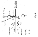
- Fig. 1 is a schematic force diagram of a portion of a vehicle rear suspension
- Fig. 2 is a close up perspective view of a variable compliance actuator within a portion of a vehicle rear suspension
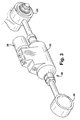
- Fig. 3 is a perspective view of the variable compliance actuator
- Fig. 4 is a schematic cross-sectional view of the variable compliance actuator.
- Fig. 1 shows the conceptual arrangement of a trailing arm rear suspension, at the rear passenger wheel, with two lateral support links and a mainly, longitudinally mounted trailing arm.
- the lateral links indicated by springs in the diagram represent the combination of a nearly solid link plus a source of compliance such as a rubber bushing at either end or just one end of each link. They connect the wheel carrier on the right side to the vehicle body or sub-frame attachments (points A, B).
- the trailing arm may be either rigidly mounted to the wheel carrier, may have a joint at the interface or may employ a connection through a rubber bushing wherein small relative motions of the knuckle with respect to the trailing arm may occur. It is also helpful, but not necessary, for the forward end of the trailing arm to be attached to the vehicle body through a bushing with a relatively low lateral and longitudinal rate so as not to the restrict the motion of the combined wheel carrier and trailing arm assembly.
- the lateral arm spring rates of the forward and rearward arm may be selected appropriately to achieve a prescribed amount of wheel carrier toe change under a given lateral load. It is also helpful that the effective arm stiffness of the rear lateral arm is higher than the front lateral arm (i.e. K LB > K LA ). This, along with the difference in length of longitudinal distances LA and LB, creates a robust mechanism for achieving the desired toe change with lateral load.
- Fig. 2 shows a representative suspension arrangement 10, around a rear wheel on the driver's side of a vehicle, that consists of a multilink construction with 3 supporting lateral control arms 12, 14 and 20.
- the forward attachment of a longitudinal trailing arm 13 to the body at point A incorporates a bushing 15 with a low lateral rate of movement, thus permitting lateral movement of the bolted knuckle/arm assembly 17 under lateral loading of the suspension.
- the trailing arm 13 may be oriented parallel to the longitudinal axis of the vehicle.
- the rear lower lateral control arm 12 (which also supports load from a vertical spring) is designed to be stiff laterally so as to maintain high lateral rigidity in the contact patch of the tire 21. This is needed to support dynamic wheel load changes and to produce a quickly responding lateral force during driving.
- the rear lower lateral control arm 12 is located to the rear of a transverse axis B-B extending from the wheel hub 23, the control arm 12 location being comparable to the schematic location of the rearward lateral link in the conceptual suspension shown in schematic Fig. 1 .
- the upper lateral support arm 14 is designed with a ball joint 16 on one end and a stiff bushing 18 on the other so as to provide stiff lateral support such that camber rigidity of the suspension can be maintained, also producing the generation of quick side forces at the tire contact patch.
- the upper 14 and lower 12 arms may be placed at any distance, vertically offset from the transverse B-B axis of the hub.
- the suspension layout is designed to create a high sensitivity of the toe change at the knuckle to the stiffness change in a particular arm, namely the forward lower suspension arm 20.
- Forward suspension arm 20 is located forward of the transverse hub axis B-B (in a position similar to the forward lateral link in schematic Fig. 1 ). This location, in combination with the ability to change the arm stiffness relates strongly to the desired value of lateral force compliance toe change.
- the range of stiffness for the combined arm and the stiffness of its associated end bushings produces a vehicle dynamics change that is significant in the state of the art of vehicle dynamics.
- the forward lower lateral arm 20 is an arm provided with variable compliance properties. It is comprised of a variable compliance actuator 22 at the center of the arm along with bushings in mounts 24 and 26 on either end.
- the inboard mount at point 26 is attached to the body itself or to a chassis sub-frame structure whereas the outboard mount at point 24 is connected to the trailing arm (or alternatively the knuckle itself).
- the actuator 22 situated in the arm 20 itself is capable of providing a base stiffness (lower end value) and a high stiffness (upper end value).
- the mechanism for creating this stiffness change is the throttling of hydraulic fluid between different chambers in the variable compliance actuator 22.
- a small, low power valve 28 is capable of either fully opening an orifice of the valve (allowing free flow of the fluid to one side or the other of a small piston within the device) or closing the valve fully (prohibiting flow of fluid from one side to the other).
- the base stiffness of the arm is determined by the design of the internal, mechanical components of the variable stiffness device (spring rate) along with the selection of the bushing rates of the bushings in mounts 24 and 26 at either end of the variable stiffness control arm 20.
- spring rate the variable stiffness device
- the high stiffness in the locked state is determined by the compliance of the internal, hydraulic circuit and seals of the device in the closed-valve state along with the stiffness of the bushing rates of the bushings in mounts 24 and 26 at either end.
- Toggling between the two states (open and hydraulically locked) via actuation of the valve through electrical control creates states of stiffness that are between the soft (fully open) and hard (hydraulically locked) states.
- An electronic controller (not shown) is used to vary the valve state by providing electrical control signals to the electronically controlled, hydraulic valve 28.
- the overall hydraulic passage properties of the compliance actuator 22 in the middle of the control arm 20, the base stiffness of the compliance actuator (and surrounding structure) in the middle of the control arm 20 in the open state, and the end bushings in mounts 24 and 26 are selected in such a way as to achieve a certain range of toe change per unit of lateral force in the tire contact patch (lateral force toe compliance rate).
- the change in the lateral force toe compliance rate between the minimal value (stiff) and high value (soft) is sufficient to change the vehicle dynamics turning behavior in all regimes of vehicle speed and loading.
- Bushing stiffness is selected at the time of vehicle assembly.
- the control parameters for deciding the desired stiffness of the semi-active compliance arm 20 are derived from existing sensor data already available from existing chassis control units such as Electronic Stability Control (ESC), Anti-lock Braking System (ABS), etc.
- ESC Electronic Stability Control
- ABS Anti-lock Braking System
- height sensors or alternatively, an algorithm capable of estimating vehicle loading condition, are used to change the toe compliance status depending on the estimated loading condition of the vehicle.
- Fig. 4 shows a schematic cut-away view of the compliance actuator 22 shown fully in Fig. 3 .
- This element is a tube-shaped component with mounts used for fastening components which are to be attached to the element.
- the mounts 24 and 26 associated with the element each include a mounting eye and an inserted elastomer sleeve bushing.
- the sleeve bushings of the mounts include at least one metallic inner piece to be fastened to the component to be joined and one elastomer bearing body encasing the inner piece and fixed to the inner piece through vulcanization.
- the compliance actuator 22 comprises a piston cylinder system 36.
- the cylinder 38 of the piston cylinder system 36 In the interior of the cylinder 38 of the piston cylinder system 36 are at least two chambers 40 that receive hydraulic or pneumatic fluid and are separated from one another by the piston 41.
- the chambers 40 are connected to one another by a channel or connecting passage 42 containing the controllable valve 28.
- the lower lateral arm 20 assumes a stiffness state.
- the state of maximum stiffness is when the valve 28 is closed, whereby this stiffness is almost exclusively determined by the stiffness of the mounts 24 and 26 with respect to the elastomer bushings therein, and whereby its stiffness can be reduced by a partial opening of the valve 28 in the passage 42 between the chambers 40 of the piston cylinder system 36.
- the chambers 40 arranged for the hydraulic or pneumatic fluid within the cylinder 38 of the piston cylinder system 36 are connected by an external connecting passage 42.
- the valve 28 is inserted into the connecting passage 42 which passes through the cylinder wall in the vicinity of the chambers 40.
- the connecting passage 42 between the chambers 40 is opened, closed, or the flow of the hydraulic medium can be continuously varied.
- the valve 28 can also be a valve which permits continuously variable regulation of flow in the range of states between closed and open. In this last instance, for example, the signals of acceleration sensors can be evaluated and used to control the valve.
- piston rod(s) 44 By means of piston rod(s) 44, the piston 41 is guided within the piston cylinder system 36.
- One piston rod 44 is connected directly or indirectly to the first mount 24.
- Cup springs 46 are arranged in each of the chambers 40. In the state of reduced stiffness of the compliance actuator 20, compared to the state of maximum stiffness, the total stiffness is influenced by the cup springs 46.
- the cup springs 46 each touch the piston 41 so that the piston 41 is elastically seated against the surfaces bordering the chambers. By this, a severe striking of the piston against the chamber walls is avoided in the event of imposition of high vibration amplitudes through the wheel.
- the control arm stiffness is set to a firm setting in order to enhance vehicle gain and responsiveness.
- the timing and activation of the inner/outer wheel can be asymmetric in order to optimize the response.
- the actuation leads more towards a more nominally open or soft state where the actuator produces less vehicle gain by permitting more lateral force toe-in (and hence more understeer at the rear axle) and enables a margin for high speed stability and control.
- the trailing arm may be comprised of multiple arms.
- the trailing arm in any form, may be at an angle, from parallel to 30 degrees offset from the longitudinal axis of the vehicle.
- the mounting sections 24 and 26, described as sleeve bushings may be replaced with ball joints or pillow joints.
Landscapes
- Engineering & Computer Science (AREA)
- Mechanical Engineering (AREA)
- General Engineering & Computer Science (AREA)
- Vehicle Body Suspensions (AREA)
Abstract
Description
- In the field of vehicle dynamics, the design and specification of a suspension system includes many different tradeoffs, such as ride comfort vs. stability. In addition to this, the performance of a vehicle with respect to various operational parameters such as loading, vehicle speed, vehicle condition, etc. must be considered. Usually suspensions end up being a compromise between a wide variety of attributes that include both performance as well as cost/weight constraints.
- Recently, in the design and manufacture of suspension systems, there has been a promulgation of active systems such as those including controllable dampers, controllable air springs, and active wheel toe change. Active wheel toe change is used to steer either the front or rear wheels via a control signal derived from various chassis sensors (lateral acceleration, steering angle, etc.) in order to change lateral and yaw response characteristics either to improve stability or to create unique response traits for a given vehicle concept. These active systems are generally more costly than a pure passive suspension, require considerable power in order to create activation, and are subject to failsafe risks requiring them to have highly developed fault risk protection systems in order to be deployed safely in chassis application.
- What is needed is a system that can produce similar changes in vehicle response behavior without large requirements for control power and the development intensive challenges related to failsafe and control logic.
- Suspensions are designed in view of a variety of constraints including cost, weight, packaging, load management, etc. The analysis of a given passive suspension type can reveal the critical characteristics that lead to toe change under the presence of vertical wheel travel (also known in the art as kinematic toe change) or that arising from lateral loading on the suspension (lateral force toe change).
- In the present suspension, the effects of kinematic toe change are negated. However, the geometric arrangement of control arms coupled with stiffness characteristics of bushings that link the control arms to the body and the wheel carrier (hub) can significantly change the amount of toe change under the presence of lateral loading forces generated by a tire during cornering. A re-design and orientation of a particular suspension's layout can be optimized to take advantage of this relationship by stressing the importance of bushing stiffness at a small number of points that, when changed, can significantly change the toe characteristics of the suspension under lateral tire force loading.
- The present vehicle suspension includes a hub for supporting a vehicle wheel, a trailing arm secured to the hub and also secured to the body of the vehicle, a first lateral arm located, relative to the vehicle, rearward of the rotational axis of the wheel, the first lateral arm being secured to the hub and also secured to the vehicle body and being generally transverse to the longitudinal axis of the vehicle, and a second lateral arm located, relative to the vehicle, upward of the rotational axis of the wheel and upward of the first lateral arm, the second lateral arm being secured to the hub and also secured to the vehicle body and being generally transverse to the longitudinal axis of the vehicle.
- The present suspension also includes a third lateral arm located, relative to the vehicle, forward of the rotational axis of the wheel, the third lateral arm being secured to the trailing arm and also secured to the body of the vehicle and comprising a variable stiffness actuator, wherein the variable stiffness actuator includes a hydraulic circuit with an electronically controlled orifice where the open state of the orifice provides a fluid flow state in the actuator such that the third lateral arm is in a least stiff state, thus, affecting toe properties of the vehicle wheel.
- These and other features, aspects and advantages of the present invention will be fully described by the following description, appended claims, and accompanying drawings.
-
Fig. 1 is a schematic force diagram of a portion of a vehicle rear suspension; -
Fig. 2 is a close up perspective view of a variable compliance actuator within a portion of a vehicle rear suspension; -
Fig. 3 . is a perspective view of the variable compliance actuator; and -
Fig. 4 is a schematic cross-sectional view of the variable compliance actuator. -
Fig. 1 shows the conceptual arrangement of a trailing arm rear suspension, at the rear passenger wheel, with two lateral support links and a mainly, longitudinally mounted trailing arm. The lateral links indicated by springs in the diagram (left hand sides indicated by points A, B) represent the combination of a nearly solid link plus a source of compliance such as a rubber bushing at either end or just one end of each link. They connect the wheel carrier on the right side to the vehicle body or sub-frame attachments (points A, B). - Of interest to this arrangement is the manner in which the wheel carrier moves in response to a tire side force applied laterally at nearly the center of the wheel carrier (indicated in the figure as an inward force). By locating the forward lower lateral link closer to a transverse hub axis than the rearward lower lateral link and providing a lower spring coefficient within the forward lower lateral link as compared to the rearward lateral link, the lateral force of the tire produces a prescribed amount of toe-in of the wheel carrier (the deflection represented by δA exceeds δB). Both the spring rates and distances LA and LB are determined via experimentation to provide a robust mechanism for achieving a desired toe change with changes in lateral load. The trailing arm may be either rigidly mounted to the wheel carrier, may have a joint at the interface or may employ a connection through a rubber bushing wherein small relative motions of the knuckle with respect to the trailing arm may occur. It is also helpful, but not necessary, for the forward end of the trailing arm to be attached to the vehicle body through a bushing with a relatively low lateral and longitudinal rate so as not to the restrict the motion of the combined wheel carrier and trailing arm assembly.
- The lateral arm spring rates of the forward and rearward arm may be selected appropriately to achieve a prescribed amount of wheel carrier toe change under a given lateral load. It is also helpful that the effective arm stiffness of the rear lateral arm is higher than the front lateral arm (i.e. KLB > KLA). This, along with the difference in length of longitudinal distances LA and LB, creates a robust mechanism for achieving the desired toe change with lateral load.
-
Fig. 2 shows arepresentative suspension arrangement 10, around a rear wheel on the driver's side of a vehicle, that consists of a multilink construction with 3 supportinglateral control arms longitudinal trailing arm 13 to the body at point A incorporates abushing 15 with a low lateral rate of movement, thus permitting lateral movement of the bolted knuckle/arm assembly 17 under lateral loading of the suspension. Thetrailing arm 13 may be oriented parallel to the longitudinal axis of the vehicle. - The rear lower lateral control arm 12 (which also supports load from a vertical spring) is designed to be stiff laterally so as to maintain high lateral rigidity in the contact patch of the
tire 21. This is needed to support dynamic wheel load changes and to produce a quickly responding lateral force during driving. The rear lowerlateral control arm 12 is located to the rear of a transverse axis B-B extending from thewheel hub 23, thecontrol arm 12 location being comparable to the schematic location of the rearward lateral link in the conceptual suspension shown in schematicFig. 1 . The upperlateral support arm 14 is designed with aball joint 16 on one end and astiff bushing 18 on the other so as to provide stiff lateral support such that camber rigidity of the suspension can be maintained, also producing the generation of quick side forces at the tire contact patch. The upper 14 and lower 12 arms may be placed at any distance, vertically offset from the transverse B-B axis of the hub. - The suspension layout is designed to create a high sensitivity of the toe change at the knuckle to the stiffness change in a particular arm, namely the forward
lower suspension arm 20.Forward suspension arm 20 is located forward of the transverse hub axis B-B (in a position similar to the forward lateral link in schematicFig. 1 ). This location, in combination with the ability to change the arm stiffness relates strongly to the desired value of lateral force compliance toe change. In particular, the range of stiffness for the combined arm and the stiffness of its associated end bushings produces a vehicle dynamics change that is significant in the state of the art of vehicle dynamics. - Referring to
Figs. 2 and3 , the forward lowerlateral arm 20 is an arm provided with variable compliance properties. It is comprised of avariable compliance actuator 22 at the center of the arm along with bushings inmounts point 26 is attached to the body itself or to a chassis sub-frame structure whereas the outboard mount atpoint 24 is connected to the trailing arm (or alternatively the knuckle itself). Theactuator 22 situated in thearm 20 itself is capable of providing a base stiffness (lower end value) and a high stiffness (upper end value). The mechanism for creating this stiffness change is the throttling of hydraulic fluid between different chambers in thevariable compliance actuator 22. A small,low power valve 28 is capable of either fully opening an orifice of the valve (allowing free flow of the fluid to one side or the other of a small piston within the device) or closing the valve fully (prohibiting flow of fluid from one side to the other). In the state of thevalve 28 being open, the base stiffness of the arm is determined by the design of the internal, mechanical components of the variable stiffness device (spring rate) along with the selection of the bushing rates of the bushings inmounts stiffness control arm 20. With thevalve 28 in the fully closed state, there is hydraulic lock of the valve and this allows a higher overall stiffness of theactuator 22 and thereby thearm 20. The high stiffness in the locked state is determined by the compliance of the internal, hydraulic circuit and seals of the device in the closed-valve state along with the stiffness of the bushing rates of the bushings inmounts - Toggling between the two states (open and hydraulically locked) via actuation of the valve through electrical control creates states of stiffness that are between the soft (fully open) and hard (hydraulically locked) states. An electronic controller (not shown) is used to vary the valve state by providing electrical control signals to the electronically controlled,
hydraulic valve 28. The overall hydraulic passage properties of thecompliance actuator 22 in the middle of thecontrol arm 20, the base stiffness of the compliance actuator (and surrounding structure) in the middle of thecontrol arm 20 in the open state, and the end bushings inmounts - The control parameters for deciding the desired stiffness of the
semi-active compliance arm 20 are derived from existing sensor data already available from existing chassis control units such as Electronic Stability Control (ESC), Anti-lock Braking System (ABS), etc. In addition to this, height sensors, or alternatively, an algorithm capable of estimating vehicle loading condition, are used to change the toe compliance status depending on the estimated loading condition of the vehicle. -
Fig. 4 shows a schematic cut-away view of thecompliance actuator 22 shown fully inFig. 3 . This element is a tube-shaped component with mounts used for fastening components which are to be attached to the element. Themounts - Within the region arranged between the
mounts compliance actuator 22 comprises apiston cylinder system 36. In the interior of thecylinder 38 of thepiston cylinder system 36 are at least twochambers 40 that receive hydraulic or pneumatic fluid and are separated from one another by thepiston 41. Thechambers 40 are connected to one another by a channel or connectingpassage 42 containing thecontrollable valve 28. Depending upon the activation of thevalve 28, the lowerlateral arm 20 assumes a stiffness state. The state of maximum stiffness is when thevalve 28 is closed, whereby this stiffness is almost exclusively determined by the stiffness of themounts valve 28 in thepassage 42 between thechambers 40 of thepiston cylinder system 36. - The
chambers 40 arranged for the hydraulic or pneumatic fluid within thecylinder 38 of thepiston cylinder system 36 are connected by an external connectingpassage 42. Thevalve 28 is inserted into the connectingpassage 42 which passes through the cylinder wall in the vicinity of thechambers 40. By means of thevalve 28, the connectingpassage 42 between thechambers 40 is opened, closed, or the flow of the hydraulic medium can be continuously varied. As needed, thevalve 28 can also be a valve which permits continuously variable regulation of flow in the range of states between closed and open. In this last instance, for example, the signals of acceleration sensors can be evaluated and used to control the valve. - By means of piston rod(s) 44, the
piston 41 is guided within thepiston cylinder system 36. Onepiston rod 44 is connected directly or indirectly to thefirst mount 24. - Cup springs 46 are arranged in each of the
chambers 40. In the state of reduced stiffness of thecompliance actuator 20, compared to the state of maximum stiffness, the total stiffness is influenced by the cup springs 46. The cup springs 46 each touch thepiston 41 so that thepiston 41 is elastically seated against the surfaces bordering the chambers. By this, a severe striking of the piston against the chamber walls is avoided in the event of imposition of high vibration amplitudes through the wheel. - In use, at low vehicle speeds, the control arm stiffness is set to a firm setting in order to enhance vehicle gain and responsiveness. The timing and activation of the inner/outer wheel (left or right wheel on a common axle) can be asymmetric in order to optimize the response. As speed increases, the actuation leads more towards a more nominally open or soft state where the actuator produces less vehicle gain by permitting more lateral force toe-in (and hence more understeer at the rear axle) and enables a margin for high speed stability and control.
- As opposed to a single part, the trailing arm may be comprised of multiple arms. The trailing arm, in any form, may be at an angle, from parallel to 30 degrees offset from the longitudinal axis of the vehicle. The mounting
sections - Although the invention has been shown and described with reference to certain preferred and alternate embodiments, the invention is not limited to these specific embodiments. Minor variations and insubstantial differences in the various combinations of materials and methods of application may occur to those of ordinary skill in the art while remaining within the scope of the invention as claimed and equivalents.
Claims (15)
- A vehicle suspension comprising:a hub for supporting a vehicle wheel;a trailing arm secured to the hub and also secured to the body of the vehicle;a first lateral arm located, relative to the vehicle, rearward of the rotational axis of the wheel, said first lateral arm being secured to the hub and also secured to the vehicle body and being generally transverse to the longitudinal axis of the vehicle;a second lateral arm located, relative to the vehicle, upward of the rotational axis of the wheel and upward of the first lateral arm, said second lateral arm being secured to the hub and also secured to the vehicle body and being generally transverse to the longitudinal axis of the vehicle;a third lateral arm located, relative to the vehicle, forward of the rotational axis of the wheel, said third lateral arm being secured to the trailing arm and also secured to the body of the vehicle and comprising a variable stiffness actuator;wherein the variable stiffness actuator includes a hydraulic circuit with an electronically controlled orifice where the open state of the orifice provides a fluid flow state in the actuator such that the third lateral arm is in a least stiff state, thus, affecting toe properties of the vehicle wheel.
- The vehicle suspension of claim 1, wherein the orifice of the stiffness actuator can be placed into a closed condition that provides a fluid flow state in the actuator such that the third lateral arm is in a most stiff state.
- The vehicle suspension of claim 1, wherein the variable compliance arm is a piston and cylinder system.
- The vehicle suspension of claim 3, further including means for varying the degree of closing of the actuator orifice via electronic control of the hydraulic valve situated in the fluid passage between the two sides of the piston in the actuator.
- The vehicle suspension of claim 1, further comprising vehicle sensors of vehicle wheel loading and vehicle speed and a controller that varies the fluid flow state of the actuator based on vehicle speed and wheel loading.
- The vehicle suspension of claim 1, wherein the trailing arm is parallel to the longitudinal axis of the vehicle.
- The vehicle suspension of claim 1, wherein the upper lateral support arm has a ball joint on one end and a stiff bushing on the other end.
- The vehicle suspension of claim 1, wherein stiff bushing mounts are provided on either end of the variable compliance arm.
- The vehicle suspension of claim 3, wherein in the cylinder at least two chambers receive hydraulic or pneumatic fluid and are separated from one another by the piston.
- The vehicle suspension of claim 9, wherein the variable compliance arm includes cup springs therein for seating the piston against surfaces bordering the chambers.
- The vehicle suspension of claim 1, further comprising and vehicle acceleration sensor that controls opening of the orifice of the stiffness actuator.
- A method for controlling a vehicle suspension comprising the steps of:providing:a hub for supporting a vehicle wheel;a trailing arm secured to the hub and also secured to the body of the vehicle;a first lateral arm located, relative to the vehicle, forward of the rotational axis of the wheel, said first lateral arm being secured to the hub and also secured to the vehicle body and being generally transverse to the trailing arm;a second lateral arm located, relative to the vehicle, upward of the rotational axis of the wheel and upward of the first lateral arm, said second lateral arm being secured to the hub and also secured to the vehicle body and being generally transverse to the trailing arm;a third lateral arm located, relative to the vehicle, forward of the rotational axis of the wheel, said third lateral arm being secured to the hub and also secured to the body of the vehicle and comprising a variable stiffness actuator;controlling an orifice within the variable stiffness actuator electronically, to fully open a hydraulic circuit, where the open state of the orifice and circuit provides a fluid flow state in the actuator such that the third lateral arm is in a least stiff state.
- The method for controlling a vehicle suspension claim 12, wherein the orifice of the stiffness actuator is placed into a closed condition that provides a fluid flow state in the actuator such that the third lateral arm is in a stiff state.
- The method for controlling a vehicle suspension of claim 13, wherein as vehicle speed increases, the orifice is opened to a greater degree, thus providing a more soft states and more toe-in of the vehicle wheel.
- The method for controlling a vehicle suspension of claim 12, further including means for varying the degree of closing of the actuator orifice via electronics.
Applications Claiming Priority (1)
| Application Number | Priority Date | Filing Date | Title |
|---|---|---|---|
| US12/464,544 US7984915B2 (en) | 2009-05-12 | 2009-05-12 | Rear suspension with semi-active toe force compliance control |
Publications (2)
| Publication Number | Publication Date |
|---|---|
| EP2251217A1 true EP2251217A1 (en) | 2010-11-17 |
| EP2251217B1 EP2251217B1 (en) | 2018-04-25 |
Family
ID=42046438
Family Applications (1)
| Application Number | Title | Priority Date | Filing Date |
|---|---|---|---|
| EP10156945.7A Not-in-force EP2251217B1 (en) | 2009-05-12 | 2010-03-18 | Rear suspension with semi-active toe force compliance control |
Country Status (3)
| Country | Link |
|---|---|
| US (1) | US7984915B2 (en) |
| EP (1) | EP2251217B1 (en) |
| JP (1) | JP5675132B2 (en) |
Cited By (8)
| Publication number | Priority date | Publication date | Assignee | Title |
|---|---|---|---|---|
| WO2013185859A1 (en) * | 2012-06-14 | 2013-12-19 | Skf B.V. | Vehicle system for active wheel angle adjustment |
| WO2016000085A1 (en) * | 2014-07-03 | 2016-01-07 | Duss Evolution Gmbh | Lateral suspension and damping system for wheels on vehicles |
| WO2017016553A1 (en) * | 2015-07-30 | 2017-02-02 | Schaeffler Technologies AG & Co. KG | Elastic chassis link for a vehicle |
| US9855806B1 (en) | 2016-07-12 | 2018-01-02 | Hyundai Motor Company | Carrier for suspension system of vehicles |
| CN107719052A (en) * | 2013-03-28 | 2018-02-23 | 株式会社斯巴鲁 | Draft hitch |
| US11167610B2 (en) * | 2017-08-22 | 2021-11-09 | Zf Friedrichshafen Ag | Wheel suspension for a motor vehicle |
| DE102020113947A1 (en) | 2020-05-25 | 2021-11-25 | Audi Aktiengesellschaft | Wheel suspension for a vehicle rear axle |
| DE102020114437A1 (en) | 2020-05-29 | 2021-12-02 | Audi Aktiengesellschaft | Wheel suspension for a vehicle rear axle |
Families Citing this family (33)
| Publication number | Priority date | Publication date | Assignee | Title |
|---|---|---|---|---|
| FR2916413B1 (en) * | 2007-05-23 | 2010-01-15 | Michelin Soc Tech | WHEEL ASSEMBLY OF A MOTOR VEHICLE COMPRISING A BIT ACTUATOR FOR ADJUSTING THE ANGULAR POSITION OF THE WHEEL PLANE. |
| DE102008001097A1 (en) * | 2008-04-09 | 2009-10-22 | Zf Friedrichshafen Ag | Elastic connecting element with variable rigidity |
| JP5005067B2 (en) * | 2010-05-28 | 2012-08-22 | 本田技研工業株式会社 | Suspension device |
| CA2801334C (en) | 2010-06-03 | 2020-03-10 | Polaris Industries Inc. | Electronic throttle control |
| US8746719B2 (en) * | 2010-08-03 | 2014-06-10 | Polaris Industries Inc. | Side-by-side vehicle |
| WO2013025510A2 (en) * | 2011-08-15 | 2013-02-21 | University Of Florida Research Foundation, Inc. | Variable stiffness mechanism |
| KR101518886B1 (en) * | 2011-12-09 | 2015-05-12 | 현대자동차 주식회사 | Active roll control system |
| CN104136244B (en) * | 2012-02-23 | 2016-08-24 | 丰田自动车株式会社 | Suspension device for vehicle |
| US9205717B2 (en) | 2012-11-07 | 2015-12-08 | Polaris Industries Inc. | Vehicle having suspension with continuous damping control |
| CA2890996C (en) | 2012-11-07 | 2023-03-21 | Polaris Industries Inc. | Vehicle having suspension with continuous damping control |
| DE102013202527A1 (en) * | 2013-02-15 | 2014-08-21 | Bayerische Motoren Werke Aktiengesellschaft | Rear axle of a two-lane vehicle |
| DE102014104176A1 (en) * | 2013-03-28 | 2014-10-02 | Fuji Jukogyo Kabushiki Kaisha | suspension device |
| JP6030521B2 (en) * | 2013-08-30 | 2016-11-24 | 本田技研工業株式会社 | Rear wheel suspension device |
| CN107406094B (en) | 2014-10-31 | 2020-04-14 | 北极星工业有限公司 | System and method for controlling a vehicle |
| MX2017014403A (en) | 2015-05-15 | 2018-04-11 | Polaris Inc | UTILITY VEHICLE. |
| US10195916B2 (en) * | 2015-10-20 | 2019-02-05 | Ford Global Technologies, Llc | Suspension isolation portions, and suspension members incorporating same |
| DE102016200096A1 (en) * | 2016-01-07 | 2017-07-13 | Zf Friedrichshafen Ag | Arm |
| CA3043481C (en) | 2016-11-18 | 2022-07-26 | Polaris Industries Inc. | Vehicle having adjustable suspension |
| US10406884B2 (en) | 2017-06-09 | 2019-09-10 | Polaris Industries Inc. | Adjustable vehicle suspension system |
| JP6605010B2 (en) * | 2017-11-27 | 2019-11-13 | 本田技研工業株式会社 | Wheel steering device |
| US10946736B2 (en) | 2018-06-05 | 2021-03-16 | Polaris Industries Inc. | All-terrain vehicle |
| US10987987B2 (en) | 2018-11-21 | 2021-04-27 | Polaris Industries Inc. | Vehicle having adjustable compression and rebound damping |
| DE102018220235A1 (en) | 2018-11-26 | 2020-05-28 | Ford Global Technologies, Llc | Independent wheel suspension for a motor vehicle |
| CA3299413A1 (en) | 2019-04-30 | 2026-03-02 | Polaris Industries Inc. | Vehicle with removable final drive |
| US12187127B2 (en) | 2020-05-15 | 2025-01-07 | Polaris Industries Inc. | Off-road vehicle |
| US11691674B2 (en) | 2020-05-15 | 2023-07-04 | Polaris Industries Inc. | Off-road vehicle |
| US12397878B2 (en) | 2020-05-20 | 2025-08-26 | Polaris Industries Inc. | Systems and methods of adjustable suspensions for off-road recreational vehicles |
| MX2022015902A (en) | 2020-07-17 | 2023-01-24 | Polaris Inc | Adjustable suspensions and vehicle operation for off-road recreational vehicles. |
| MX2023006716A (en) | 2022-06-13 | 2023-12-14 | Polaris Inc | POWER TRAIN FOR UTILITY VEHICLE. |
| CN115195861B (en) * | 2022-08-12 | 2023-09-12 | 浙江极氪智能科技有限公司 | Toe-in adjusting device and vehicle |
| USD1067123S1 (en) | 2023-01-20 | 2025-03-18 | Polaris Industries Inc. | Off-road vehicle |
| DE102023107955A1 (en) | 2023-03-29 | 2024-10-02 | Dr. Ing. H.C. F. Porsche Aktiengesellschaft | motor vehicle |
| USD1120805S1 (en) | 2023-06-29 | 2026-03-31 | Polaris Industries Inc. | Body assembly for an off-road vehicle |
Citations (4)
| Publication number | Priority date | Publication date | Assignee | Title |
|---|---|---|---|---|
| GB2163104A (en) * | 1984-08-14 | 1986-02-19 | Honda Motor Co Ltd | Fluid controlled bushings in a suspension link |
| US4706989A (en) * | 1985-06-12 | 1987-11-17 | Nissan Motor Co., Ltd. | Rear independent suspension for automotive vehicle |
| DE3703618A1 (en) * | 1987-02-06 | 1988-08-18 | Opel Adam Ag | Rear axle for a motor vehicle |
| WO2009124543A1 (en) * | 2008-04-09 | 2009-10-15 | Zf Friedrichshafen Ag | Elastic connection element with variable rigidity |
Family Cites Families (10)
| Publication number | Priority date | Publication date | Assignee | Title |
|---|---|---|---|---|
| EP0302226B1 (en) * | 1983-09-02 | 1993-11-24 | Mazda Motor Corporation | Vehicle rear suspension system |
| JPH0611203Y2 (en) * | 1985-07-03 | 1994-03-23 | 本田技研工業株式会社 | Suspension with trailing arm |
| JPH0669774B2 (en) * | 1985-11-08 | 1994-09-07 | 三菱自動車工業株式会社 | Vehicle rear suspension device |
| JPS6280173A (en) * | 1985-10-03 | 1987-04-13 | Mazda Motor Corp | Four wheel steering device for vehicle |
| JPH0274408A (en) * | 1988-09-09 | 1990-03-14 | Mazda Motor Corp | Suspension device for vehicle |
| JPH02216309A (en) * | 1989-02-15 | 1990-08-29 | Mazda Motor Corp | Suspension device for vehicle |
| JPH02306815A (en) * | 1989-05-22 | 1990-12-20 | Toyota Motor Corp | Vehicle suspension device |
| JPH0664437A (en) * | 1992-08-17 | 1994-03-08 | Nissan Motor Co Ltd | Vehicle suspension system |
| FR2830586B1 (en) * | 2001-10-08 | 2004-07-09 | Valeo | CLUTCH, IN PARTICULAR FOR MOTOR VEHICLE, WITH PNEUMATIC CONTROL |
| JP2004314917A (en) * | 2003-04-21 | 2004-11-11 | Honda Motor Co Ltd | Vehicle suspension device |
-
2009
- 2009-05-12 US US12/464,544 patent/US7984915B2/en not_active Expired - Fee Related
-
2010
- 2010-03-10 JP JP2010052937A patent/JP5675132B2/en not_active Expired - Fee Related
- 2010-03-18 EP EP10156945.7A patent/EP2251217B1/en not_active Not-in-force
Patent Citations (4)
| Publication number | Priority date | Publication date | Assignee | Title |
|---|---|---|---|---|
| GB2163104A (en) * | 1984-08-14 | 1986-02-19 | Honda Motor Co Ltd | Fluid controlled bushings in a suspension link |
| US4706989A (en) * | 1985-06-12 | 1987-11-17 | Nissan Motor Co., Ltd. | Rear independent suspension for automotive vehicle |
| DE3703618A1 (en) * | 1987-02-06 | 1988-08-18 | Opel Adam Ag | Rear axle for a motor vehicle |
| WO2009124543A1 (en) * | 2008-04-09 | 2009-10-15 | Zf Friedrichshafen Ag | Elastic connection element with variable rigidity |
Cited By (10)
| Publication number | Priority date | Publication date | Assignee | Title |
|---|---|---|---|---|
| WO2013185859A1 (en) * | 2012-06-14 | 2013-12-19 | Skf B.V. | Vehicle system for active wheel angle adjustment |
| CN107719052A (en) * | 2013-03-28 | 2018-02-23 | 株式会社斯巴鲁 | Draft hitch |
| CN107719052B (en) * | 2013-03-28 | 2020-04-10 | 株式会社斯巴鲁 | Suspension device |
| WO2016000085A1 (en) * | 2014-07-03 | 2016-01-07 | Duss Evolution Gmbh | Lateral suspension and damping system for wheels on vehicles |
| WO2017016553A1 (en) * | 2015-07-30 | 2017-02-02 | Schaeffler Technologies AG & Co. KG | Elastic chassis link for a vehicle |
| US10625551B2 (en) | 2015-07-30 | 2020-04-21 | Schaeffler Technologies AG & Co. KG | Elastic chassis link for a vehicle |
| US9855806B1 (en) | 2016-07-12 | 2018-01-02 | Hyundai Motor Company | Carrier for suspension system of vehicles |
| US11167610B2 (en) * | 2017-08-22 | 2021-11-09 | Zf Friedrichshafen Ag | Wheel suspension for a motor vehicle |
| DE102020113947A1 (en) | 2020-05-25 | 2021-11-25 | Audi Aktiengesellschaft | Wheel suspension for a vehicle rear axle |
| DE102020114437A1 (en) | 2020-05-29 | 2021-12-02 | Audi Aktiengesellschaft | Wheel suspension for a vehicle rear axle |
Also Published As
| Publication number | Publication date |
|---|---|
| EP2251217B1 (en) | 2018-04-25 |
| JP2010264972A (en) | 2010-11-25 |
| US20100289229A1 (en) | 2010-11-18 |
| US7984915B2 (en) | 2011-07-26 |
| JP5675132B2 (en) | 2015-02-25 |
Similar Documents
| Publication | Publication Date | Title |
|---|---|---|
| US7984915B2 (en) | Rear suspension with semi-active toe force compliance control | |
| CN1709728B (en) | active vehicle suspension | |
| US9517673B2 (en) | Vehicle and a suspension system for the vehicle | |
| US7717438B2 (en) | Chassis system for a motor vehicle and method for driving dynamics regulation | |
| KR102733403B1 (en) | Vehicle motion control device | |
| CN100475579C (en) | Method for controlling and regulating an active chassis system | |
| CN104709023B (en) | Method and apparatus for the Active Suspensions damping including negative stiffness | |
| BR102017015965B1 (en) | METHOD AND DEVICE FOR ADJUSTING THE DAMPING FORCE OF ADJUSTABLE SHOCK ABSORBERS OF A DRIVER'S CAB ASSEMBLY | |
| US6619672B2 (en) | Suspension device having a trim corrector | |
| JP4563013B2 (en) | Vehicle suspension system | |
| US20090140479A1 (en) | Variable compliance suspension bushing | |
| CN111032374B (en) | Wheel suspension for motor vehicles | |
| JP4239804B2 (en) | Vehicle stabilization control device | |
| CN110997356A (en) | Axle with centrally arranged drive unit | |
| WO2006129065A1 (en) | Suspension systems | |
| CN104136244B (en) | Suspension device for vehicle | |
| Liu | Recent innovations in vehicle suspension systems | |
| CN113246676A (en) | Continuously variable rate fluid spring system for vehicle and method of operating the same | |
| KR100405543B1 (en) | judder reduction system for lower arm | |
| JP2008126810A (en) | Fixing device for vehicle | |
| WO2010118114A1 (en) | Variable compliance link | |
| Bauer | Design Examples | |
| Fijalkowski | ABW AWA Suspension Mechatronic Control Systems | |
| GB2405381A (en) | Five-link vehicle suspension system | |
| JPH0717526Y2 (en) | Fluid pressure active suspension |
Legal Events
| Date | Code | Title | Description |
|---|---|---|---|
| PUAI | Public reference made under article 153(3) epc to a published international application that has entered the european phase |
Free format text: ORIGINAL CODE: 0009012 |
|
| AK | Designated contracting states |
Kind code of ref document: A1 Designated state(s): AT BE BG CH CY CZ DE DK EE ES FI FR GB GR HR HU IE IS IT LI LT LU LV MC MK MT NL NO PL PT RO SE SI SK SM TR |
|
| AX | Request for extension of the european patent |
Extension state: AL BA ME RS |
|
| RIN1 | Information on inventor provided before grant (corrected) |
Inventor name: KRAMER, KLAUS Inventor name: MARKOSKI, JON Inventor name: POST, JAMES W. |
|
| 17P | Request for examination filed |
Effective date: 20110512 |
|
| RIC1 | Information provided on ipc code assigned before grant |
Ipc: F16F 9/20 20060101ALI20170629BHEP Ipc: B60G 17/015 20060101ALI20170629BHEP Ipc: B62D 7/22 20060101ALI20170629BHEP Ipc: B60G 7/00 20060101AFI20170629BHEP Ipc: F16F 9/46 20060101ALI20170629BHEP Ipc: F16F 9/19 20060101ALI20170629BHEP |
|
| GRAP | Despatch of communication of intention to grant a patent |
Free format text: ORIGINAL CODE: EPIDOSNIGR1 |
|
| STAA | Information on the status of an ep patent application or granted ep patent |
Free format text: STATUS: GRANT OF PATENT IS INTENDED |
|
| INTG | Intention to grant announced |
Effective date: 20171026 |
|
| GRAS | Grant fee paid |
Free format text: ORIGINAL CODE: EPIDOSNIGR3 |
|
| GRAJ | Information related to disapproval of communication of intention to grant by the applicant or resumption of examination proceedings by the epo deleted |
Free format text: ORIGINAL CODE: EPIDOSDIGR1 |
|
| GRAL | Information related to payment of fee for publishing/printing deleted |
Free format text: ORIGINAL CODE: EPIDOSDIGR3 |
|
| STAA | Information on the status of an ep patent application or granted ep patent |
Free format text: STATUS: REQUEST FOR EXAMINATION WAS MADE |
|
| GRAR | Information related to intention to grant a patent recorded |
Free format text: ORIGINAL CODE: EPIDOSNIGR71 |
|
| STAA | Information on the status of an ep patent application or granted ep patent |
Free format text: STATUS: GRANT OF PATENT IS INTENDED |
|
| INTC | Intention to grant announced (deleted) | ||
| GRAA | (expected) grant |
Free format text: ORIGINAL CODE: 0009210 |
|
| STAA | Information on the status of an ep patent application or granted ep patent |
Free format text: STATUS: THE PATENT HAS BEEN GRANTED |
|
| INTG | Intention to grant announced |
Effective date: 20180307 |
|
| AK | Designated contracting states |
Kind code of ref document: B1 Designated state(s): AT BE BG CH CY CZ DE DK EE ES FI FR GB GR HR HU IE IS IT LI LT LU LV MC MK MT NL NO PL PT RO SE SI SK SM TR |
|
| REG | Reference to a national code |
Ref country code: GB Ref legal event code: FG4D |
|
| REG | Reference to a national code |
Ref country code: CH Ref legal event code: EP |
|
| REG | Reference to a national code |
Ref country code: AT Ref legal event code: REF Ref document number: 992469 Country of ref document: AT Kind code of ref document: T Effective date: 20180515 |
|
| REG | Reference to a national code |
Ref country code: IE Ref legal event code: FG4D |
|
| REG | Reference to a national code |
Ref country code: DE Ref legal event code: R096 Ref document number: 602010050130 Country of ref document: DE |
|
| REG | Reference to a national code |
Ref country code: NL Ref legal event code: MP Effective date: 20180425 |
|
| REG | Reference to a national code |
Ref country code: LT Ref legal event code: MG4D |
|
| PG25 | Lapsed in a contracting state [announced via postgrant information from national office to epo] |
Ref country code: NL Free format text: LAPSE BECAUSE OF FAILURE TO SUBMIT A TRANSLATION OF THE DESCRIPTION OR TO PAY THE FEE WITHIN THE PRESCRIBED TIME-LIMIT Effective date: 20180425 |
|
| PG25 | Lapsed in a contracting state [announced via postgrant information from national office to epo] |
Ref country code: ES Free format text: LAPSE BECAUSE OF FAILURE TO SUBMIT A TRANSLATION OF THE DESCRIPTION OR TO PAY THE FEE WITHIN THE PRESCRIBED TIME-LIMIT Effective date: 20180425 Ref country code: LT Free format text: LAPSE BECAUSE OF FAILURE TO SUBMIT A TRANSLATION OF THE DESCRIPTION OR TO PAY THE FEE WITHIN THE PRESCRIBED TIME-LIMIT Effective date: 20180425 Ref country code: BG Free format text: LAPSE BECAUSE OF FAILURE TO SUBMIT A TRANSLATION OF THE DESCRIPTION OR TO PAY THE FEE WITHIN THE PRESCRIBED TIME-LIMIT Effective date: 20180725 Ref country code: FI Free format text: LAPSE BECAUSE OF FAILURE TO SUBMIT A TRANSLATION OF THE DESCRIPTION OR TO PAY THE FEE WITHIN THE PRESCRIBED TIME-LIMIT Effective date: 20180425 Ref country code: PL Free format text: LAPSE BECAUSE OF FAILURE TO SUBMIT A TRANSLATION OF THE DESCRIPTION OR TO PAY THE FEE WITHIN THE PRESCRIBED TIME-LIMIT Effective date: 20180425 Ref country code: NO Free format text: LAPSE BECAUSE OF FAILURE TO SUBMIT A TRANSLATION OF THE DESCRIPTION OR TO PAY THE FEE WITHIN THE PRESCRIBED TIME-LIMIT Effective date: 20180725 Ref country code: SE Free format text: LAPSE BECAUSE OF FAILURE TO SUBMIT A TRANSLATION OF THE DESCRIPTION OR TO PAY THE FEE WITHIN THE PRESCRIBED TIME-LIMIT Effective date: 20180425 |
|
| PG25 | Lapsed in a contracting state [announced via postgrant information from national office to epo] |
Ref country code: LV Free format text: LAPSE BECAUSE OF FAILURE TO SUBMIT A TRANSLATION OF THE DESCRIPTION OR TO PAY THE FEE WITHIN THE PRESCRIBED TIME-LIMIT Effective date: 20180425 Ref country code: HR Free format text: LAPSE BECAUSE OF FAILURE TO SUBMIT A TRANSLATION OF THE DESCRIPTION OR TO PAY THE FEE WITHIN THE PRESCRIBED TIME-LIMIT Effective date: 20180425 Ref country code: GR Free format text: LAPSE BECAUSE OF FAILURE TO SUBMIT A TRANSLATION OF THE DESCRIPTION OR TO PAY THE FEE WITHIN THE PRESCRIBED TIME-LIMIT Effective date: 20180726 |
|
| REG | Reference to a national code |
Ref country code: AT Ref legal event code: MK05 Ref document number: 992469 Country of ref document: AT Kind code of ref document: T Effective date: 20180425 |
|
| PG25 | Lapsed in a contracting state [announced via postgrant information from national office to epo] |
Ref country code: PT Free format text: LAPSE BECAUSE OF FAILURE TO SUBMIT A TRANSLATION OF THE DESCRIPTION OR TO PAY THE FEE WITHIN THE PRESCRIBED TIME-LIMIT Effective date: 20180827 |
|
| REG | Reference to a national code |
Ref country code: DE Ref legal event code: R097 Ref document number: 602010050130 Country of ref document: DE |
|
| PG25 | Lapsed in a contracting state [announced via postgrant information from national office to epo] |
Ref country code: RO Free format text: LAPSE BECAUSE OF FAILURE TO SUBMIT A TRANSLATION OF THE DESCRIPTION OR TO PAY THE FEE WITHIN THE PRESCRIBED TIME-LIMIT Effective date: 20180425 Ref country code: DK Free format text: LAPSE BECAUSE OF FAILURE TO SUBMIT A TRANSLATION OF THE DESCRIPTION OR TO PAY THE FEE WITHIN THE PRESCRIBED TIME-LIMIT Effective date: 20180425 Ref country code: AT Free format text: LAPSE BECAUSE OF FAILURE TO SUBMIT A TRANSLATION OF THE DESCRIPTION OR TO PAY THE FEE WITHIN THE PRESCRIBED TIME-LIMIT Effective date: 20180425 Ref country code: EE Free format text: LAPSE BECAUSE OF FAILURE TO SUBMIT A TRANSLATION OF THE DESCRIPTION OR TO PAY THE FEE WITHIN THE PRESCRIBED TIME-LIMIT Effective date: 20180425 Ref country code: CZ Free format text: LAPSE BECAUSE OF FAILURE TO SUBMIT A TRANSLATION OF THE DESCRIPTION OR TO PAY THE FEE WITHIN THE PRESCRIBED TIME-LIMIT Effective date: 20180425 Ref country code: SK Free format text: LAPSE BECAUSE OF FAILURE TO SUBMIT A TRANSLATION OF THE DESCRIPTION OR TO PAY THE FEE WITHIN THE PRESCRIBED TIME-LIMIT Effective date: 20180425 |
|
| PG25 | Lapsed in a contracting state [announced via postgrant information from national office to epo] |
Ref country code: SM Free format text: LAPSE BECAUSE OF FAILURE TO SUBMIT A TRANSLATION OF THE DESCRIPTION OR TO PAY THE FEE WITHIN THE PRESCRIBED TIME-LIMIT Effective date: 20180425 Ref country code: IT Free format text: LAPSE BECAUSE OF FAILURE TO SUBMIT A TRANSLATION OF THE DESCRIPTION OR TO PAY THE FEE WITHIN THE PRESCRIBED TIME-LIMIT Effective date: 20180425 |
|
| PLBE | No opposition filed within time limit |
Free format text: ORIGINAL CODE: 0009261 |
|
| STAA | Information on the status of an ep patent application or granted ep patent |
Free format text: STATUS: NO OPPOSITION FILED WITHIN TIME LIMIT |
|
| 26N | No opposition filed |
Effective date: 20190128 |
|
| PG25 | Lapsed in a contracting state [announced via postgrant information from national office to epo] |
Ref country code: SI Free format text: LAPSE BECAUSE OF FAILURE TO SUBMIT A TRANSLATION OF THE DESCRIPTION OR TO PAY THE FEE WITHIN THE PRESCRIBED TIME-LIMIT Effective date: 20180425 |
|
| PG25 | Lapsed in a contracting state [announced via postgrant information from national office to epo] |
Ref country code: MC Free format text: LAPSE BECAUSE OF FAILURE TO SUBMIT A TRANSLATION OF THE DESCRIPTION OR TO PAY THE FEE WITHIN THE PRESCRIBED TIME-LIMIT Effective date: 20180425 |
|
| REG | Reference to a national code |
Ref country code: CH Ref legal event code: PL |
|
| PG25 | Lapsed in a contracting state [announced via postgrant information from national office to epo] |
Ref country code: LU Free format text: LAPSE BECAUSE OF NON-PAYMENT OF DUE FEES Effective date: 20190318 |
|
| REG | Reference to a national code |
Ref country code: BE Ref legal event code: MM Effective date: 20190331 |
|
| PG25 | Lapsed in a contracting state [announced via postgrant information from national office to epo] |
Ref country code: LI Free format text: LAPSE BECAUSE OF NON-PAYMENT OF DUE FEES Effective date: 20190331 Ref country code: IE Free format text: LAPSE BECAUSE OF NON-PAYMENT OF DUE FEES Effective date: 20190318 Ref country code: CH Free format text: LAPSE BECAUSE OF NON-PAYMENT OF DUE FEES Effective date: 20190331 |
|
| PG25 | Lapsed in a contracting state [announced via postgrant information from national office to epo] |
Ref country code: FR Free format text: LAPSE BECAUSE OF NON-PAYMENT OF DUE FEES Effective date: 20190331 Ref country code: BE Free format text: LAPSE BECAUSE OF NON-PAYMENT OF DUE FEES Effective date: 20190331 |
|
| PG25 | Lapsed in a contracting state [announced via postgrant information from national office to epo] |
Ref country code: TR Free format text: LAPSE BECAUSE OF FAILURE TO SUBMIT A TRANSLATION OF THE DESCRIPTION OR TO PAY THE FEE WITHIN THE PRESCRIBED TIME-LIMIT Effective date: 20180425 |
|
| PGFP | Annual fee paid to national office [announced via postgrant information from national office to epo] |
Ref country code: GB Payment date: 20200325 Year of fee payment: 11 |
|
| PG25 | Lapsed in a contracting state [announced via postgrant information from national office to epo] |
Ref country code: MT Free format text: LAPSE BECAUSE OF NON-PAYMENT OF DUE FEES Effective date: 20190318 |
|
| PG25 | Lapsed in a contracting state [announced via postgrant information from national office to epo] |
Ref country code: CY Free format text: LAPSE BECAUSE OF FAILURE TO SUBMIT A TRANSLATION OF THE DESCRIPTION OR TO PAY THE FEE WITHIN THE PRESCRIBED TIME-LIMIT Effective date: 20180425 |
|
| PG25 | Lapsed in a contracting state [announced via postgrant information from national office to epo] |
Ref country code: IS Free format text: LAPSE BECAUSE OF FAILURE TO SUBMIT A TRANSLATION OF THE DESCRIPTION OR TO PAY THE FEE WITHIN THE PRESCRIBED TIME-LIMIT Effective date: 20180825 |
|
| PG25 | Lapsed in a contracting state [announced via postgrant information from national office to epo] |
Ref country code: HU Free format text: LAPSE BECAUSE OF FAILURE TO SUBMIT A TRANSLATION OF THE DESCRIPTION OR TO PAY THE FEE WITHIN THE PRESCRIBED TIME-LIMIT; INVALID AB INITIO Effective date: 20100318 |
|
| GBPC | Gb: european patent ceased through non-payment of renewal fee |
Effective date: 20210318 |
|
| PG25 | Lapsed in a contracting state [announced via postgrant information from national office to epo] |
Ref country code: GB Free format text: LAPSE BECAUSE OF NON-PAYMENT OF DUE FEES Effective date: 20210318 |
|
| PGFP | Annual fee paid to national office [announced via postgrant information from national office to epo] |
Ref country code: DE Payment date: 20220330 Year of fee payment: 13 |
|
| PG25 | Lapsed in a contracting state [announced via postgrant information from national office to epo] |
Ref country code: MK Free format text: LAPSE BECAUSE OF FAILURE TO SUBMIT A TRANSLATION OF THE DESCRIPTION OR TO PAY THE FEE WITHIN THE PRESCRIBED TIME-LIMIT Effective date: 20180425 |
|
| REG | Reference to a national code |
Ref country code: DE Ref legal event code: R119 Ref document number: 602010050130 Country of ref document: DE |
|
| PG25 | Lapsed in a contracting state [announced via postgrant information from national office to epo] |
Ref country code: DE Free format text: LAPSE BECAUSE OF NON-PAYMENT OF DUE FEES Effective date: 20231003 |