EP0136563B2 - Vehicle rear suspension system - Google Patents
Vehicle rear suspension system Download PDFInfo
- Publication number
- EP0136563B2 EP0136563B2 EP84110400A EP84110400A EP0136563B2 EP 0136563 B2 EP0136563 B2 EP 0136563B2 EP 84110400 A EP84110400 A EP 84110400A EP 84110400 A EP84110400 A EP 84110400A EP 0136563 B2 EP0136563 B2 EP 0136563B2
- Authority
- EP
- European Patent Office
- Prior art keywords
- wheel
- swing arm
- lateral
- suspension system
- wheel carrying
- Prior art date
- Legal status (The legal status is an assumption and is not a legal conclusion. Google has not performed a legal analysis and makes no representation as to the accuracy of the status listed.)
- Expired - Lifetime
Links
Images

Classifications
-
- B—PERFORMING OPERATIONS; TRANSPORTING
- B60—VEHICLES IN GENERAL
- B60G—VEHICLE SUSPENSION ARRANGEMENTS
- B60G3/00—Resilient suspensions for a single wheel
- B60G3/18—Resilient suspensions for a single wheel with two or more pivoted arms, e.g. parallelogram
- B60G3/20—Resilient suspensions for a single wheel with two or more pivoted arms, e.g. parallelogram all arms being rigid
- B60G3/22—Resilient suspensions for a single wheel with two or more pivoted arms, e.g. parallelogram all arms being rigid a rigid arm forming the axle housing
-
- B—PERFORMING OPERATIONS; TRANSPORTING
- B60—VEHICLES IN GENERAL
- B60G—VEHICLE SUSPENSION ARRANGEMENTS
- B60G3/00—Resilient suspensions for a single wheel
- B60G3/18—Resilient suspensions for a single wheel with two or more pivoted arms, e.g. parallelogram
- B60G3/28—Resilient suspensions for a single wheel with two or more pivoted arms, e.g. parallelogram at least one of the arms itself being resilient, e.g. leaf spring
- B60G3/285—Resilient suspensions for a single wheel with two or more pivoted arms, e.g. parallelogram at least one of the arms itself being resilient, e.g. leaf spring the arm being essentially parallel to the longitudinal axis of the vehicle
-
- B—PERFORMING OPERATIONS; TRANSPORTING
- B60—VEHICLES IN GENERAL
- B60G—VEHICLE SUSPENSION ARRANGEMENTS
- B60G2200/00—Indexing codes relating to suspension types
- B60G2200/10—Independent suspensions
- B60G2200/18—Multilink suspensions, e.g. elastokinematic arrangements
- B60G2200/182—Multilink suspensions, e.g. elastokinematic arrangements with one longitudinal arm or rod and lateral rods
-
- B—PERFORMING OPERATIONS; TRANSPORTING
- B60—VEHICLES IN GENERAL
- B60G—VEHICLE SUSPENSION ARRANGEMENTS
- B60G2202/00—Indexing codes relating to the type of spring, damper or actuator
- B60G2202/30—Spring/Damper and/or actuator Units
- B60G2202/31—Spring/Damper and/or actuator Units with the spring arranged around the damper, e.g. MacPherson strut
- B60G2202/312—The spring being a wound spring
Definitions
- the present invention relates to a vehicle suspension system and more particularly to a non driven rear wheel suspension system of a motor vehicle in accordance with the preamble of claim 1.
- a vehicle rear suspension system of that kind is known from U-A-4 269 432.
- Conventional independent type vehicle rear suspension system include a so-called trailing arm type and a semi-trailing arm type.
- These types of suspension systems include a trailing arm extending in a longitudinal direction of the vehicle body and having a front end attached to the vehicle body for vertical swinging movements, the trailing arm being secured at the rear end to a hub carrier which carries a rear wheel hub.
- a substantially vertically extending damping strut is provided between the rear end portion of the trailing arm and the vehicle body.
- the suspension systems of these types are advantageous in that they are simple in structure so that the overall weight can be decreased.
- the suspension systems of these types require trailing arm of substantial cross-sectional area in order to ensure an adequate lateral rigidity.
- the front end of the trailing arm must be attached to the vehicle body at laterally spaced positions. As the results, the trailina arm must be of a substantial dimension and therefore of an increased weight.
- Utility model JP-U-56-62205 discloses a vehicle rear suspension system including a trailing arm having a front end mounted on a vehicle body for vertical swinging movements and a rear and carrying a wheel hub, to provide a pair of vertically spaced lateral links which are pivotably connected at the laterally outward ends to the rear end portions of the trailing arm and at the laterally inward ends to the vehicle body.
- This type of suspension system is advantageous in that the lateral links supports the trailing arm so that the trailing arm may not be required to possess by itself a substantial lateral rigidity. It should however be noted that in this arrangement there are produced toe-out movements in the wheel when the wheel is bumped upwards with respect to the vehicle body and when the wheel is rebounced downwards with respect to the vehicle body. Such toe-out movements cause a tendency of over-steer in a curved path so that there will be a danger of steering instability.
- DE-B-923 346 discloses a driven rear wheel suspension system comprising swing arm means extending substantially longitudinally, wheel carrying means for carrying a rear wheel for rotation about a rotation axis, said wheel carrying means being rigidly connected with said swing arm means, and three lateral link means extending in substantially lateral direction of the vehicle body.
- the three lateral links are of the same length and parallel to each other. They are connected to the wheel carrying means at locations which are not aligned on a single straight line.
- Each of the lateral links has both ends connected to the vehicle body and the wheel carrying means, respectively, pivotably about a single pivot means.
- This suspension system has the disadvantage that since the wheel carrying means and the swing arm means form one rigid member, the orientation of the wheel carrying means is constrained by the swing arm means, and since the lateral link means are of the same length and parallel to each other desirable camber angle and toe-angle characteristics cannot be achieved.
- DE-A-2 038 880 also discloses a driven rear wheel suspension system comprising swing arm means extending substantially longitudinally, wheel carrying means for carrying a rear wheel, the wheel carrying means being rotatably connected with the swing arm means, the swing arm means having a low lateral rigidity which does not constrain the lateral movement of the wheel carrying means to thereby enable the camber and toe-angle of the rear wheel to be controlled by the lateral link means.
- This suspension system suffers the disadvantage that braking forces are transmitted to the lateral link members.
- the upper lateral link member has an A-shaped configuration being connected to the vehicle body by two pivot means and therfore requires a large amount of space both for connection to the vehicle body and for permitting movement of the link.
- a further object of the present invention is to provide a vehicle rear suspension system which can suppress toe-out movements of the wheel under vertical bumping movements.
- a further object of the present invention is to provide a vehicle rear suspension system of a type including a susbtantially longitudinally extending swing arm for carrying a rear wheel and laterally extending links, which can suppress toe-out movements of the wheel under vertical bumping movements to thereby improve stability of the vehicle.
- Still further object of the present invention is to provide a vehicle rear suspension system in which axial forces applied to the lateral links can be minimized.
- Yet further object of the present invention is to provide a vehicle rear suspension system in which toe-in movements are produced in the rear wheel under braking forces.
- a further object of the present invention is to provide a vehicle rear suspension system which can suppress toe-out movements of the rear wheel under vertical bumping movements and can produce desirable changes in toe-angles under side forces which are applied to the wheel when the vehicle is running through a curved path.
- Still further object of the present invention is to provide a vehicle rear suspension system which can desirably control both the camber angle and the toe-angle of the rear wheel.
- Still further object of the present invention is to provide a vehicle rear suspension system which can minimize the tread change in upward bouncing and downward rebouncing of the rear wheel.
- the orientation of the wheel carrying means and therefore that of the rear wheel is determined only by the three lateral link means. Therefore, it becomes possible to control the toe-angle and the camber angle of the rear wheel in a desired manner under either or all of upward bumping and downward rebouncing of the rear wheel and side and longitudinal forces applied to the rear wheel by simply determining the arrangements of the lateral link means. For example, the inclination of each lateral link means in a horizontal plane and that in a vertical plane may appropriately be determined. In addition, or alternatively, the lengths of the respective lateral link means, the positions of connections of the lateral link means to the wheel carrying means and the lateral rigidity of the connections between the lateral link means to the wheel carrying means may appropriately be determined to obtain desired results.
- the swing arm means may simply possess strength and rigidity sufficient for transmitting longitudinal forces and rotating forces about a lateral axis. It is necessary that the swing arm means does not constrain the wheel carrying means so that the orientation of the wheel carrying means be controlled by the three lateral link means.
- the swing arm means may have low lateral rigidity so that the swing arm means be capable of deflecting in lateral directions under upward bouncing and downward rebouncing of the rear wheel.
- the swing arm means may be connected with the wheel carrying means so that a rotation about a vertical axis or a lateral relative displacement is permitted.
- one of the lateral link means is connected to the wheel carrying means at a position higher than positions where the other two lateral link means are connected with the wheel carrying means, the said positions being so located that a cornering force acting point on the rear wheel is between imaginary lines passing through the first mentioned position and respective ones of the second mentioned positions.
- the first mentioned position is located above the rotation axis of the rear wheel and the second mentioned positions are located below the rotation axis.
- the aforementioned other two link means are preferably arranged so that projections in a horizontal plane of extensions of their longitudinal axes intersect each other outward said rear wheel. This particular arrangement is effective to produce a toe-in movement of the rear wheel under a braking force.
- the second lateral link means is connected to the wheel carrying means at a position above the rotation axis of the rear wheel, the first lateral link means being connected at a position below and forward the rotation axis and the third lateral link means being connected at a position below and rearward the rotation axis, the second lateral link means being shorter than the third lateral link means.
- the first lateral link means is preferably connected to the wheel carrying means forward a line passing through the cornering force acting point on the rear wheel and the position where the second lateral link is connected to the wheel carrying means, the third lateral link means being connected to the wheel carrying means rearward of the aforementioned line, the distance between the position of connection of the second lateral link means and the aforementioned line being smaller than that between the position of connection of the third lateral link means and the aforementioned line.
- the arrangement is effective to produce a toe-in movement of the rear wheel under an inwardly directed side force.
- the second and third link means are arranged rearward the first link means, the second link means being above and shorter than the third lateral link means, projections is a vertical transverse plane of longitudinal axes of the second and third lateral link means intersecting each other at a point inward the rear wheel, the first link means being shorter than the second and third link means.
- a vehicle rear left wheel 10 which is carried by a wheel carrying member 12 for rotation about a rotation axis L4.
- a rear suspension system 14 which includes a longitudinally extending swing arm 18.
- the swing arm 18 is connected at the front end with a bracket 29 provided on a frame 28 of the vehicle body 16 by means of a rubber bush 39 and a laterally extending pin 38 so that the arm 38 is vertically swingable about a horizontal axis.
- the rear end of the swing arm 18 is secured to the wheel carrying member 12 by means of bolts 30.
- the suspension system 14 further includes a first lateral link 20, a second lateral link 22 and a third lateral link 24.
- the first lateral link 20 extends substantially transversely with respect to the vehicle body 16 and has a transverse outward end connected with the wheel carrying member 12 through a rubber bush 20a for swinging movement about a substantially longitudinal axis.
- the transverse inward end of the first lateral link 20 is connected with the body frame 28 thorugh a rubber bush 20b for swinging movement about a substantially longitudinal axis.
- the second and third lateral links 22 and 24 are connected at one ends respectively through rubber bushes 22a and 24a to the wheel carrying member 12 for swinging movements about substantially longitudinal axes, and at the other ends respectively through rubber bushes 22b and 24b to a rear sub-frame 32 of the vehicle body 16 for swinging movements about substantially longitudinal axes.
- the rubber bush 22a as typical example of the aforementioned rubber bushes. It should be noted that the other bushes have similar structures.
- a substantially vertically extending strut assembly 26 which comprises a coil spring 34 and an oleo damper 36.
- the strut assembly 26 is pivotably connected at the lower end with the wheel carrying member 12 and connected at the upper end to the vehicle body 16 so as to allow a certain degree of angular movement.
- the second lateral link 22 is connected to the wheel carrying member 12 at a position above and rearward of the wheel center 40 and the first lateral link 20 is connected at a position below and forward of the wheel center 40.
- the third lateral link 24 is connected to the wheel carrying member 12 at a position below and rearward of the wheel center 40.
- the first lateral link 20 is inclined rearward and downward and has a length shorter than those of the other two lateral links 22 and 24.
- the second lateral link 22 is inclined slightly forward and upward whereas the third lateral link 24 is inclined slightly downward.
- the first lateral link 20 has a longitudinal axis L1 and the third lateral link 24 has a longitudinal axis L2, the axes L1 and L2 intersecting each other at a point P which is laterally outwardly apart from a vertical line L3 passing through the wheel center 40 by a distance 11 and longitudinally rearwardly apart from the wheel rotation axis L4 by a distance 12. It will further be noted that projections of the axes of the second and third lateral links 22 and 24 on a transverse vertical plane intersect each other at a point inward the wheel 10. Further, the first lateral link 20 is shorter in length than the third lateral link 24.
- the swing arm 18 is swung about the pin 38 so that the wheel center 40 is moved along an arcuate path having a center of arc at the axis of the pin 38.
- the wheel carrying member 12 is laterally supported by three lateral links 20, 22 and 24 which also swing in vertical directions to produce lateral displacements at the outward ends.
- the laterally outward end of the first lateral link 20 is slightly displaced outward but the displacement is small because the link 20 is inclined rearward.
- the outer end of the second lateral link 22 is displaced inward in response to an upward hump of the wheel.
- the outer end of the third lateral link 24 is displaced outward, the distance of displacement being larger than that of the outer end of the first lateral link 20. Since the outer ends of the first and second lateral links 20 and 22 are located forward the outer end of the third lateral link 24, there is produced a slight toe-in movement. Further, there is produced a decrease in the camber angle. Under a downward rebouncing of the wheel, there are produced a slight toe-out movement and a slight increase in the camber angle. Speaking more specifically, the toe-angle of the wheel is changed as shown by a curve a in Figure 6(a).
- the swing arm 18 is of a cross-sectional configuration which provides a certain degree of deflection in lateral direction of the vehicle body, the swing arm 18 is laterally deflected as necessary as the wheel carrying member 12 is displaced as described above. Further, the rubber bush 39 permits a certain amount of lateral displacement of the swing arm.
- the rubber bush 39 includes an outer tube 39a and an inner tube 39b.
- a resilient rubber 39c is disposed between and adhered to the outer and inner tubes 39a and 39b.
- the pin 38 is inserted into the inner tube 39b to secure the inner tube 39b to the bracket 29 of the frame 28.
- the outer tube 39a is welded to the swing arm 18. It will be understood in Figure 5 that the rubber bush 39 is deflected as shown by phantom lines to permit a lateral displacement of the swing arm 18.
- the embodiment shown therein is different from the previous embodiment in that the second lateral link 22 is connected to the wheel carrying member 12 at a location above and forward of the wheel center 40.
- the second lateral link 22 is connected to the wheel carrying member 12 at a location above and forward of the wheel center 40.
- a moment produced by the side force F acting on a point P1 is balanced by a moment produced by an axial compression force F3 in the third lateral link 24.
- Figure 8 shows another embodiment of the present invention in which corresponding parts are designated by the same reference numerals.
- FIG 8 there is drawn on imaginary line L7 which passes through the center of the rubber bush 22a and the side force acting point P1 on the wheel 10.
- the distance l1 between the center of the rubber bush 20a and the imaginary line L7 is smaller than the distance l2 between the center of the rubber bush 24a and the imaginary line L7.
- the axial compression force F1 produced in the first lateral link 20 under the side force F becomes greater than that F3 in the third lateral link 24.
- Figure 9 shows a modification of the arrangement of Figure 8 and a similar toe-in movement of the wheel 10 is produced under a side force F.
- the embodiment shown therein is different from the previously described embodiments in that the rubber bush 39 for connecting the front end of the swing arm 18 has an axis 391 which is inwardly and rearwardly inclined with respect to a transverse direction of the vehicle body.
- the swing arm 18 is deflected inward as shown by phantom lines to permit inward displacement of the wheel carrying member 12.
- an axial deformation is produced in the rubber bush 39 causing a slight rearward displacement of the swing arm 18 and therefore a corresponding rearward displacement of the wheel carrying member 12.
Landscapes
- Engineering & Computer Science (AREA)
- Mechanical Engineering (AREA)
- Vehicle Body Suspensions (AREA)
Description
- The present invention relates to a vehicle suspension system and more particularly to a non driven rear wheel suspension system of a motor vehicle in accordance with the preamble of claim 1.
- A vehicle rear suspension system of that kind is known from U-A-4 269 432.
- Conventional independent type vehicle rear suspension system include a so-called trailing arm type and a semi-trailing arm type. These types of suspension systems include a trailing arm extending in a longitudinal direction of the vehicle body and having a front end attached to the vehicle body for vertical swinging movements, the trailing arm being secured at the rear end to a hub carrier which carries a rear wheel hub. A substantially vertically extending damping strut is provided between the rear end portion of the trailing arm and the vehicle body. The suspension systems of these types are advantageous in that they are simple in structure so that the overall weight can be decreased. There has however been recognized that the suspension systems of these types require trailing arm of substantial cross-sectional area in order to ensure an adequate lateral rigidity. Further, the front end of the trailing arm must be attached to the vehicle body at laterally spaced positions. As the results, the trailina arm must be of a substantial dimension and therefore of an increased weight.
- This type of suspension system also has the disadvantage that during braking longitudinal reaction forces are produced in the lateral link members supporting the wheel carrying member for counteracting the moment produced by the braking force, and therefore the risk of brake judder is increased. Utility model JP-U-56-62205 discloses a vehicle rear suspension system including a trailing arm having a front end mounted on a vehicle body for vertical swinging movements and a rear and carrying a wheel hub, to provide a pair of vertically spaced lateral links which are pivotably connected at the laterally outward ends to the rear end portions of the trailing arm and at the laterally inward ends to the vehicle body. This type of suspension system is advantageous in that the lateral links supports the trailing arm so that the trailing arm may not be required to possess by itself a substantial lateral rigidity. It should however be noted that in this arrangement there are produced toe-out movements in the wheel when the wheel is bumped upwards with respect to the vehicle body and when the wheel is rebounced downwards with respect to the vehicle body. Such toe-out movements cause a tendency of over-steer in a curved path so that there will be a danger of steering instability.
- DE-B-923 346 discloses a driven rear wheel suspension system
comprising swing arm means extending substantially longitudinally, wheel carrying means for carrying a rear wheel for rotation about a rotation axis, said wheel carrying means being rigidly connected with said swing arm means, and three lateral link means extending in substantially lateral direction of the vehicle body. The three lateral links are of the same length and parallel to each other. They are connected to the wheel carrying means at locations which are not aligned on a single straight line. Each of the lateral links has both ends connected to the vehicle body and the wheel carrying means, respectively, pivotably about a single pivot means. - This suspension system has the disadvantage that since the wheel carrying means and the swing arm means form one rigid member, the orientation of the wheel carrying means is constrained by the swing arm means, and since the lateral link means are of the same length and parallel to each other desirable camber angle and toe-angle characteristics cannot be achieved.
- DE-A-2 038 880 also discloses a driven rear wheel suspension system comprising swing arm means extending substantially longitudinally, wheel carrying means for carrying a rear wheel, the wheel carrying means being rotatably connected with the swing arm means, the swing arm means having a low lateral rigidity which does not constrain the lateral movement of the wheel carrying means to thereby enable the camber and toe-angle of the rear wheel to be controlled by the lateral link means. This suspension system suffers the disadvantage that braking forces are transmitted to the lateral link members. A further disadvantage is that the upper lateral link member has an A-shaped configuration being connected to the vehicle body by two pivot means and therfore requires a large amount of space both for connection to the vehicle body and for permitting movement of the link.
- It is therefore an object of the invention to provide a non-driven rear wheel suspension system corresponding to the preamble of claim 1, which is compact and in which the lateral link means are not subjected to longitudinal braking forces but are able to control the orientation of the wheel carrying means without being constrained by the swing arm means. This object is achieved by means of the characterising features of claim 1.
- It is a further object of the present invention to provide a vehicle rear suspension system which can provide an improved stability of the vehicle.
- A further object of the present invention is to provide a vehicle rear suspension system which can suppress toe-out movements of the wheel under vertical bumping movements.
- A further object of the present invention is to provide a vehicle rear suspension system of a type including a susbtantially longitudinally extending swing arm for carrying a rear wheel and laterally extending links, which can suppress toe-out movements of the wheel under vertical bumping movements to thereby improve stability of the vehicle.
- Still further object of the present invention is to provide a vehicle rear suspension system in which axial forces applied to the lateral links can be minimized.
- Yet further object of the present invention is to provide a vehicle rear suspension system in which toe-in movements are produced in the rear wheel under braking forces.
- A further object of the present invention is to provide a vehicle rear suspension system which can suppress toe-out movements of the rear wheel under vertical bumping movements and can produce desirable changes in toe-angles under side forces which are applied to the wheel when the vehicle is running through a curved path.
- Still further object of the present invention is to provide a vehicle rear suspension system which can desirably control both the camber angle and the toe-angle of the rear wheel.
- Still further object of the present invention is to provide a vehicle rear suspension system which can minimize the tread change in upward bouncing and downward rebouncing of the rear wheel.
- The above further objects of the present invention are achieved by means of the features disclosed in the dependent claims which correspond to preferred embodiments of the invention.
- According to the above arrangement of the present invention, the orientation of the wheel carrying means and therefore that of the rear wheel is determined only by the three lateral link means. Therefore, it becomes possible to control the toe-angle and the camber angle of the rear wheel in a desired manner under either or all of upward bumping and downward rebouncing of the rear wheel and side and longitudinal forces applied to the rear wheel by simply determining the arrangements of the lateral link means. For example, the inclination of each lateral link means in a horizontal plane and that in a vertical plane may appropriately be determined. In addition, or alternatively, the lengths of the respective lateral link means, the positions of connections of the lateral link means to the wheel carrying means and the lateral rigidity of the connections between the lateral link means to the wheel carrying means may appropriately be determined to obtain desired results.
- The swing arm means may simply possess strength and rigidity sufficient for transmitting longitudinal forces and rotating forces about a lateral axis. It is necessary that the swing arm means does not constrain the wheel carrying means so that the orientation of the wheel carrying means be controlled by the three lateral link means. For the purpose, the swing arm means may have low lateral rigidity so that the swing arm means be capable of deflecting in lateral directions under upward bouncing and downward rebouncing of the rear wheel. Alternatively, the swing arm means may be connected with the wheel carrying means so that a rotation about a vertical axis or a lateral relative displacement is permitted.
- In one mode of the present invention, one of the lateral link means is connected to the wheel carrying means at a position higher than positions where the other two lateral link means are connected with the wheel carrying means, the said positions being so located that a cornering force acting point on the rear wheel is between imaginary lines passing through the first mentioned position and respective ones of the second mentioned positions. With this arrangement, it is possible to decrease the axial forces on the lateral link means under a cornering force. Preferably, the first mentioned position is located above the rotation axis of the rear wheel and the second mentioned positions are located below the rotation axis. The aforementioned other two link means are preferably arranged so that projections in a horizontal plane of extensions of their longitudinal axes intersect each other outward said rear wheel. This particular arrangement is effective to produce a toe-in movement of the rear wheel under a braking force.
- In a specific feature of the present invention, the second lateral link means is connected to the wheel carrying means at a position above the rotation axis of the rear wheel, the first lateral link means being connected at a position below and forward the rotation axis and the third lateral link means being connected at a position below and rearward the rotation axis, the second lateral link means being shorter than the third lateral link means. This arrangement is effective to suppress toe-out movements of the rear wheel under upward bumping and downward rebouncing of the rear wheel. The first lateral link means is preferably connected to the wheel carrying means forward a line passing through the cornering force acting point on the rear wheel and the position where the second lateral link is connected to the wheel carrying means, the third lateral link means being connected to the wheel carrying means rearward of the aforementioned line, the distance between the position of connection of the second lateral link means and the aforementioned line being smaller than that between the position of connection of the third lateral link means and the aforementioned line. The arrangement is effective to produce a toe-in movement of the rear wheel under an inwardly directed side force.
- In a further mode of the present invention, the second and third link means are arranged rearward the first link means, the second link means being above and shorter than the third lateral link means, projections is a vertical transverse plane of longitudinal axes of the second and third lateral link means intersecting each other at a point inward the rear wheel, the first link means being shorter than the second and third link means.
- The above and other objects and features of the present invention will become apparent from the following descriptions of preferred embodiments taking reference to the accompanying drawings, in which:
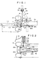
- Figure 1 is a diagrammatical top plan view of a rear suspension system in accordance with one embodiment of the present invention;
- Figure 2 is a rear view of the suspension system;
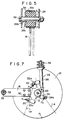
- Figure 3 is a perspective view of the suspension system;
- Figure 4 is a sectional view of a rubber bush for connecting the lateral link to the wheel carrying member;
- Figure 5 is a sectional view of the rubber bush for connecting the swing arm to the vehicle body;
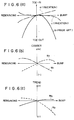
- Figure 6(a), (b), (c) are diagrams showing respectively changes in the toe-angle, the camber angle and the tread in the rear wheel under upward bumping and rebouncing movements;
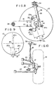
- Figure 7 is a side view as seen from inside of a suspension system in accordance with another embodiment;
- Figure 8 is a side view similar to Figure 7 but showing a further embodiment;
- Figure 9 is a diagrammatical illustration of a further embodiment of the present invention; and,
- Figure 10 is a top plan view of a rear suspension mechanism showing a further embodiment.
- Referring now to the drawings, particularly to Figures 1 through 3, there is shown a vehicle rear
left wheel 10 which is carried by awheel carrying member 12 for rotation about a rotation axis L4. Between thewheel carrying member 12 and avehicle body 16, there is arear suspension system 14 which includes a longitudinally extendingswing arm 18. Theswing arm 18 is connected at the front end with abracket 29 provided on aframe 28 of thevehicle body 16 by means of arubber bush 39 and a laterally extendingpin 38 so that thearm 38 is vertically swingable about a horizontal axis. The rear end of theswing arm 18 is secured to thewheel carrying member 12 by means ofbolts 30. - The
suspension system 14 further includes a firstlateral link 20, a secondlateral link 22 and a thirdlateral link 24. The firstlateral link 20 extends substantially transversely with respect to thevehicle body 16 and has a transverse outward end connected with thewheel carrying member 12 through arubber bush 20a for swinging movement about a substantially longitudinal axis. The transverse inward end of the firstlateral link 20 is connected with thebody frame 28 thorugh arubber bush 20b for swinging movement about a substantially longitudinal axis. The second and thirdlateral links rubber bushes 22a and 24a to thewheel carrying member 12 for swinging movements about substantially longitudinal axes, and at the other ends respectively throughrubber bushes rear sub-frame 32 of thevehicle body 16 for swinging movements about substantially longitudinal axes. In Figure 4, there is shown the rubber bush 22a as typical example of the aforementioned rubber bushes. It should be noted that the other bushes have similar structures. - Between the
wheel carrying member 12 and thevehicle body 16, there is disposed a substantially vertically extendingstrut assembly 26 which comprises acoil spring 34 and anoleo damper 36. Thestrut assembly 26 is pivotably connected at the lower end with thewheel carrying member 12 and connected at the upper end to thevehicle body 16 so as to allow a certain degree of angular movement. - In Figure 3, it will be noted that the second
lateral link 22 is connected to thewheel carrying member 12 at a position above and rearward of thewheel center 40 and the firstlateral link 20 is connected at a position below and forward of thewheel center 40. The thirdlateral link 24 is connected to thewheel carrying member 12 at a position below and rearward of thewheel center 40. As shown in Figures 1 and 3, the firstlateral link 20 is inclined rearward and downward and has a length shorter than those of the other twolateral links lateral link 22 is inclined slightly forward and upward whereas the thirdlateral link 24 is inclined slightly downward. The firstlateral link 20 has a longitudinal axis L1 and the thirdlateral link 24 has a longitudinal axis L2, the axes L1 and L2 intersecting each other at a point P which is laterally outwardly apart from a vertical line L3 passing through thewheel center 40 by a distance 11 and longitudinally rearwardly apart from the wheel rotation axis L4 by adistance 12. It will further be noted that projections of the axes of the second and thirdlateral links wheel 10. Further, the firstlateral link 20 is shorter in length than the thirdlateral link 24. - As the
wheel 10 is bumped in a vertical direction, theswing arm 18 is swung about thepin 38 so that thewheel center 40 is moved along an arcuate path having a center of arc at the axis of thepin 38. Thewheel carrying member 12 is laterally supported by threelateral links wheel 10 is upwardly bumped, the laterally outward end of the firstlateral link 20 is slightly displaced outward but the displacement is small because thelink 20 is inclined rearward. The outer end of the secondlateral link 22 is displaced inward in response to an upward hump of the wheel. Further, the outer end of the thirdlateral link 24 is displaced outward, the distance of displacement being larger than that of the outer end of the firstlateral link 20. Since the outer ends of the first and secondlateral links lateral link 24, there is produced a slight toe-in movement. Further, there is produced a decrease in the camber angle. Under a downward rebouncing of the wheel, there are produced a slight toe-out movement and a slight increase in the camber angle. Speaking more specifically, the toe-angle of the wheel is changed as shown by a curve a in Figure 6(a). The toe-angle change in the prior art suspension system of the laid-open Japanese utility model JP-U-56-62205 is shown by a curve b in Figure 6(a). Thus, the advantage of the present invention will be apparent from this diagram. Where the thirdlateral link 24 has a length sufficiently large as compared with the firstlateral link 20, there will be no noticeable displacement in the outer end of the thirdlateral link 24 so that the toe-angle change will be as shown by a curve c. It will be understood that the camber angle is changed as shown by a curve M₁ in Figure 6(b) due to the arrangements of the second and thirdlateral links wheel 10 bumps upward, thewheel carrying member 12 is displaced inward and there may be produced a decrease in tread between the rear wheels. However, in the arrangement described above, the camber angle is decreased in response to an upward bumping of the wheel and the decrease in the camber angle causes an increase in the tread. As the result, the tread changes as shown by a curve M₂ in Figure 6(c). Where the second and thirdlateral links wheel 10, the camber angle will change as shown by a curve N₁ in Figure 6(b). Then, the tread will change as shown by a curve N₂ in Figure 6(c). Since theswing arm 18 is of a cross-sectional configuration which provides a certain degree of deflection in lateral direction of the vehicle body, theswing arm 18 is laterally deflected as necessary as thewheel carrying member 12 is displaced as described above. Further, therubber bush 39 permits a certain amount of lateral displacement of the swing arm. - Referring to Figure 5, it will be noted that the
rubber bush 39 includes an outer tube 39a and aninner tube 39b. Aresilient rubber 39c is disposed between and adhered to the outer andinner tubes 39a and 39b. Thepin 38 is inserted into theinner tube 39b to secure theinner tube 39b to thebracket 29 of theframe 28. The outer tube 39a is welded to theswing arm 18. It will be understood in Figure 5 that therubber bush 39 is deflected as shown by phantom lines to permit a lateral displacement of theswing arm 18. - When a braking force is applied to the
wheel 10, therubber bush 39 is deformed to allow a slight rearward displacement of theswing arm 18. Thus, there will be produced in the wheel carrying member 12 a turning displacement about the point P of intersection of the lines L₁ and L₂. Therefore, a slight toe-in displacement is produced in therear wheel 10. When a forwardly directed traction force is applied to thewheel 10, there may be produced a toe-out displacement in thewheel 10. However, such toe-out displacement can be prevented by providing therubber bush 39 with a stopper which restricts forward deflection of therubber bush 39. - When a side force or a cornering force F is applied to the
rear wheel 10 as shown in Figures 1 and 3, there will be produced a slight toe-in displacement due to reaction forces applied from thelateral links wheel carrying member 12 since the side force acting point on thewheel 10 is forward the point P of intersection of the lines L₁ and L₂. Thus, a steering stability is ensured in operations through curved paths. It is also possible to obtain a slight toe-in displacement under an inwardly directed side force and a slight toe-out displacement under an outwardly directed side force by appropriately determining the lateral rigidity of therubber bushes lateral links wheel carrying member 12. - Referring now to Figure 7, the embodiment shown therein is different from the previous embodiment in that the second
lateral link 22 is connected to thewheel carrying member 12 at a location above and forward of thewheel center 40. In either of the previously described arrangements, it is possible to substantially equalize the axial forces produced in thelateral links rubber bushes 20a and 22a, a moment produced by the side force F acting on a point P₁ is balanced by a moment produced by an axial compression force F₃ in the thirdlateral link 24. Similarly, considering the balance of moment about a line L₆ passing through centers of therubber bushes 22a and 24a, a moment produced by the side force F is balanced by a moment produced by an axial compression force F₁ in the firstlateral link 20. In order to counterbalance these axial compression forces F₁ and F₃, there will be produced an axial tensile force F₂ in the secondlateral link 22, the sum of the forces F₁ and F₃ being substantially equal to the sum of the force F₂ and the side force F. - Figure 8 shows another embodiment of the present invention in which corresponding parts are designated by the same reference numerals. Referring to Figure 8, there is drawn on imaginary line L₇ which passes through the center of the rubber bush 22a and the side force acting point P₁ on the
wheel 10. In this embodiment, the distance l1 between the center of therubber bush 20a and the imaginary line L₇ is smaller than the distance l₂ between the center of therubber bush 24a and the imaginary line L₇. In this arrangement, the axial compression force F₁ produced in the firstlateral link 20 under the side force F becomes greater than that F₃ in the thirdlateral link 24. Such difference if the axial forces F₁ and F₃ produces a difference in deformations of therubber bushes wheel 10. Figure 9 shows a modification of the arrangement of Figure 8 and a similar toe-in movement of thewheel 10 is produced under a side force F. - Referring now to Figure 10, the embodiment shown therein is different from the previously described embodiments in that the
rubber bush 39 for connecting the front end of theswing arm 18 has anaxis 391 which is inwardly and rearwardly inclined with respect to a transverse direction of the vehicle body. With this arrangement, when thewheel 10 is bumped, theswing arm 18 is deflected inward as shown by phantom lines to permit inward displacement of thewheel carrying member 12. At the same time, an axial deformation is produced in therubber bush 39 causing a slight rearward displacement of theswing arm 18 and therefore a corresponding rearward displacement of thewheel carrying member 12. As the result, there will be produced a slight toe-in movement as described with reference to Figure 1. - The invention has been shown and described with reference to specific emodiments, however, it should be noted that the invention is in no way limited to the details of the illustrated structures but changes and modifications may be made without departing from the scope of the appended claims.
Claims (17)
- A non-driven rear wheel suspension system for a motor vehicle comprising swing arm means (18) extending substantially longitudinally and having one end connected to the vehicle body (16) for vertical swinging movements, wheel carrying means (12) for carrying a rear wheel (10) for rotation about a rotation axis (L4), said wheel carrying means (12) being connected with said swing arm means (18) at the other end of the swing arm means (18) so that a longitudinal force can be transmitted between the swing arm means (18) and the wheel carrying means (12), first (20), second (22) and third (24) lateral link means extending in substantially lateral direction of the vehicle body (16), each of said lateral link means (20, 22, 24) having one end connected with said wheel carrying means (12) pivotably about a single pivot means (20a, 22a, 24a) and the other end connected pivotably with the vehicle body (16), said one ends of the first (20), second (22) and third (24) lateral link means being connected to said wheel carrying means (12) at locations which are not aligned on a single straight line,
characterized in
that said wheel carrying means (12) is arranged to be connected through said swing arm means (18) with said vehicle body (16) so that a moment about a transverse axis extending in a lateral direction of the vehicle body (16) can be transmitted between the wheel carrying means (12) and the vehicle body (16) through the swing arm means (18)
and that said wheel carrying means (12) is supported by said swing arm means (18) in such a way that said swing arm means (18) does not constrain the lateral movement of the wheel carrying means (12) with respect to the vehicle body (16), whereby the orientation of the wheel carrying means (12) is controlled by said first, second and third lateral link means (20, 22, 24)
and that each of said lateral link means (20, 22, 24) has the other end connected pivotably with the vehicle body (16) about a single pivot means (20b, 22b, 24b), and has an inclination and length appropriately determined to control the orientation of the wheel carrying means (12), and to thereby control the camber and the toe-angle of the rear wheel. - A vehicle rear suspension system in accordance with claim 1, characterized in that said wheel carrying means (12) is connected rigidly with said swing arm means (18) at the other end of the swing arm means (18).
- A vehicle rear suspension system in accordance with one of claims 1 to 2 characterized in that said one end of the swing arm means (18) is a front end and said other end is a rear end.
- A vehicle rear suspension system in accordance with one of claims 1 to 3, characterized in that said one end of the swing arm means (18) is connected to the vehicle body (16) through rubber bush means (39) having an axis arranged in substantially lateral direction of the vehicle body (16) so as to permit lateral displacement of said swing arm means (18) to thereby permit lateral displacement of the wheel carrying means.
- A vehicle rear suspension system in accordance with one of claims 1 to 4, characterized in that said swing arm means (18) has a cross-section which provides a low rigidity in the lateral direction so as to permit lateral deflection of the swing arm means (18) thereby permitting lateral displacement of the wheel carrying means (12).
- A vehicle rear suspension system in accordance with one of claims 1-5, characterized in that one of the lateral link means (22) is connected to the wheel carrying means (12) at a position higher than positions where the other two lateral link means (20, 24) are connected with the wheel carrying means (12), the said positions being so located that a cornering force (F) acting point (P1) on the rear wheel (10) is between imaginary lines (L5, L6) passing through the first mentioned position (22a) and respective ones of the second mentioned positions (20a, 24a).
- A vehicle rear suspension system in accordance with claim 6, characterized in that the first mentioned position is located above the rotation axis (L4) of the rear wheel (10) and the second mentioned positions are located below the rotation axis (L4).
- A vehicle rear suspension system in accordance with claim 6, characterized in that the second lateral link means (22) is connected to the wheel carrying means (12) at a position above the rotation axis (L4) of the rear wheel (10), the first lateral link means (20) being connected at a position below and forward the rotation axis (L4) and the third lateral link means (24) being connected at a position below and rearward the rotation axis (L4), the first lateral link means (20) being shorter than the third lateral link means (24).
- A vehicle rear suspension system in accordance with claim 7, characterized in that said other two link means (20, 24) have axes (L1, L2) which intersect each other in a projection on a horizontal plane at a point (P) outward the rear wheel (10).
- A vehicle rear suspension system in accordance with claim 6, characterized in that forward one (20) of said other two lateral link means (20, 24) being apart from a line (L7) passing through the first mentioned position (22a) and said cornering force (F) acting point (P1) by a distance (L1) which is smaller than a distance (L2) by which rearward one (24a) of said other two lateral link means (20, 24) is apart from said line (L7).
- A vehicle rear suspension system in accordance with claim 10, characterized in that the second lateral link means (22) is connected to the wheel carrying means (12) at a position (22a) above the rotation axis (L4) of the rear wheel (10), the first lateral link means (20) being connected at a position (20a) below and forward the rotation axis (L4) and the third lateral link means (24) being connected at a position (24a) below and rearward the rotation axis (L4).
- A vehicle rear suspension system in accordance with claims 1-5 characterized in that said second (22) and third (24) link means are arranged rearward the first link means (20), the second link means (22) being above and shorter than the third lateral link means (24), projections in a vertical transverse plane of longitudinal axis of the second (22) and third (24) lateral link means intersecting each other at a point inward the rear wheel (10) the first link means (20) being shorter than the second (22) and third (24) link means.
- A vehicle rear suspension system in accordance with one of claims 1-17, characterized in that the other ends of said first (20), second (22) and third (24) lateral link means being connected to the wheel carrying means (12) at positions, respectively, below and forward, above and forward, and below and rearward the wheel rotation axis (L4), said first (20) and third (24) lateral link means having axes (L1, L2) intersecting each other in a projection on a horizontal plane at a position outward the rear wheel (10).
- A vehicle rear suspension system in accordance with one of claims 1-13, characterized in that said one end of the swing arm means (18) is connected in the vehicle body (16) through rubber bush means (39) having an axis inclined inwardly and rearwardlywith respect to a lateral direction of the vehicle body (16).
- A vehicle rear suspension system in accordance with one of claims 1-14, characterized in that said one end of the swing arm means (18) being resiliently connected to the vehicle body (16) and that said wheel carrying means (12) being connected rigidly with said swing arm means (18) at the other end of the swing arm means (18).
- A vehicle rear suspension system in accordance with one of claims 1-15 in which said swing arm means (18) is connected with the wheel carrying means (12) so that a rotation of the wheel carrying means (12) about a vertical axis is permitted.
- A vehicle rear suspension system in accordance with one of claims 1-16 in which said swing arm means (18) is connected with the wheel carrying means (12) so that a lateral relative displacement of the wheel carrying means (12) is permitted.
Applications Claiming Priority (14)
| Application Number | Priority Date | Filing Date | Title |
|---|---|---|---|
| JP161541/83 | 1983-09-02 | ||
| JP16154183A JPS6053414A (en) | 1983-09-02 | 1983-09-02 | Rear suspension of car |
| JP16153583A JPS6053408A (en) | 1983-09-02 | 1983-09-02 | Rear suspension of car |
| JP16153683A JPS6053409A (en) | 1983-09-02 | 1983-09-02 | Rear suspension of car |
| JP161538/83 | 1983-09-02 | ||
| JP161536/83 | 1983-09-02 | ||
| JP16153783A JPS6053410A (en) | 1983-09-02 | 1983-09-02 | Rear suspension of car |
| JP16153983A JPS6053412A (en) | 1983-09-02 | 1983-09-02 | Rear suspension of car |
| JP161537/83 | 1983-09-02 | ||
| JP161539/83 | 1983-09-02 | ||
| JP161535/83 | 1983-09-02 | ||
| JP16153883A JPS6053411A (en) | 1983-09-02 | 1983-09-02 | Rear suspension of car |
| JP16872383A JPS6060016A (en) | 1983-09-13 | 1983-09-13 | Rear suspension for automobile |
| JP168723/83 | 1983-09-13 |
Related Child Applications (1)
| Application Number | Title | Priority Date | Filing Date |
|---|---|---|---|
| EP88110420.2 Division-Into | 1988-06-29 |
Publications (4)
| Publication Number | Publication Date |
|---|---|
| EP0136563A2 EP0136563A2 (en) | 1985-04-10 |
| EP0136563A3 EP0136563A3 (en) | 1985-07-03 |
| EP0136563B1 EP0136563B1 (en) | 1989-10-18 |
| EP0136563B2 true EP0136563B2 (en) | 1994-04-20 |
Family
ID=27566225
Family Applications (2)
| Application Number | Title | Priority Date | Filing Date |
|---|---|---|---|
| EP88110420A Expired - Lifetime EP0302226B1 (en) | 1983-09-02 | 1984-08-31 | Vehicle rear suspension system |
| EP84110400A Expired - Lifetime EP0136563B2 (en) | 1983-09-02 | 1984-08-31 | Vehicle rear suspension system |
Family Applications Before (1)
| Application Number | Title | Priority Date | Filing Date |
|---|---|---|---|
| EP88110420A Expired - Lifetime EP0302226B1 (en) | 1983-09-02 | 1984-08-31 | Vehicle rear suspension system |
Country Status (3)
| Country | Link |
|---|---|
| US (2) | US4815755A (en) |
| EP (2) | EP0302226B1 (en) |
| DE (2) | DE3480186D1 (en) |
Cited By (1)
| Publication number | Priority date | Publication date | Assignee | Title |
|---|---|---|---|---|
| DE102013202527A1 (en) | 2013-02-15 | 2014-08-21 | Bayerische Motoren Werke Aktiengesellschaft | Rear axle of a two-lane vehicle |
Families Citing this family (60)
| Publication number | Priority date | Publication date | Assignee | Title |
|---|---|---|---|---|
| DE3480186D1 (en) * | 1983-09-02 | 1989-11-23 | Mazda Motor | Vehicle rear suspension system |
| DE3448231C2 (en) * | 1983-09-22 | 1995-12-21 | Honda Motor Co Ltd | Independent rear wheel suspension |
| DE3434790A1 (en) * | 1983-09-22 | 1985-04-18 | Honda Giken Kogyo K.K., Tokio/Tokyo | REAR SUSPENSION FOR A MOTOR VEHICLE |
| US4790560A (en) * | 1984-09-06 | 1988-12-13 | Honda Giken Kogyo Kabushiki Kaisha | Independent rear suspension for use on motor vehicles |
| US4690426A (en) * | 1984-09-06 | 1987-09-01 | Honda Giken Kogyo Kabushiki Kaisha | Trailing arm joint structure |
| EP0193847B1 (en) * | 1985-02-26 | 1990-09-12 | Mazda Motor Corporation | Vehicle rear suspension system |
| JPS61278407A (en) * | 1985-06-03 | 1986-12-09 | Honda Motor Co Ltd | Independent suspension type rear suspension |
| CA1265823A (en) * | 1985-10-04 | 1990-02-13 | Keiichi Mitobe | Independent rear wheel suspension |
| JPS62191207A (en) * | 1986-02-17 | 1987-08-21 | Toyota Motor Corp | Automobile rear wheel suspension device |
| FR2595995B1 (en) * | 1986-03-20 | 1988-07-08 | Peugeot | INDEPENDENT WHEEL SUSPENSION, ESPECIALLY REAR OF VEHICLE AND ITS APPLICATION TO A DRIVE WHEEL |
| JPS63145112A (en) * | 1986-12-09 | 1988-06-17 | Honda Motor Co Ltd | Rear suspension deice for automobile |
| JPH07100403B2 (en) * | 1986-12-15 | 1995-11-01 | マツダ株式会社 | Car suspension equipment |
| US4756546A (en) * | 1987-03-13 | 1988-07-12 | Honda Giken Kogyo Kabushiki Kaisha | Rear wheel suspension device for front and rear wheel steering vehicle |
| FR2625140B1 (en) * | 1987-12-29 | 1990-06-01 | Renault | SUSPENSION FOR MOTOR VEHICLES |
| IT1212164B (en) * | 1987-12-30 | 1989-11-08 | Fiat Auto Spa | REAR SUSPENSION FOR INDEPENDENT WHEEL VEHICLES |
| US5301932A (en) * | 1988-07-15 | 1994-04-12 | Suzuki Motor Corp. | Vehicular strut type suspension |
| US5009449A (en) * | 1988-07-27 | 1991-04-23 | Mazda Motor Corporation | Vehicle rear suspension system |
| JP2714969B2 (en) * | 1989-01-13 | 1998-02-16 | マツダ株式会社 | Automotive suspension equipment |
| US4998748A (en) * | 1989-04-04 | 1991-03-12 | Mazda Motor Corporation | Vehicle suspension system |
| FR2645475B1 (en) * | 1989-04-11 | 1994-03-25 | Renault Regie Nale Usines | SUSPENSION FOR MOTOR VEHICLES |
| US5348337A (en) * | 1991-12-27 | 1994-09-20 | Mazda Motor Corporation | Automobile suspension |
| EP0556464A1 (en) * | 1992-02-15 | 1993-08-25 | Volkswagen Aktiengesellschaft | Independent suspension for the rear wheels of a motor vehicle |
| DE9422146U1 (en) * | 1993-11-29 | 1998-04-30 | Dr.Ing.H.C. F. Porsche Ag, 70435 Stuttgart | Suspension |
| GB9514974D0 (en) * | 1995-07-21 | 1995-09-20 | Rover Group | A semi-trailing arm suspension for a vehicle |
| US6022034A (en) * | 1996-10-09 | 2000-02-08 | Toyota Jidosha Kabushiki Kaisha | Twist beam suspension |
| US5823552A (en) * | 1997-08-25 | 1998-10-20 | Chrysler Corporation | Strut type rear suspension |
| US6173978B1 (en) * | 1999-05-07 | 2001-01-16 | Zero Roll Suspension Corporation | Zero roll suspension system |
| GB9911633D0 (en) * | 1999-05-20 | 1999-07-21 | Randle Engineering Solutions L | Improved vehicle suspension |
| JP3945156B2 (en) | 2000-12-19 | 2007-07-18 | マツダ株式会社 | Car suspension equipment |
| US20040046350A1 (en) * | 2001-05-21 | 2004-03-11 | Wagner Engineering, Llc | Method and apparatus for suspending a vehicular wheel assembly |
| DE10253265A1 (en) * | 2002-11-15 | 2004-05-27 | Volkswagen Ag | Four-link rear wheel axle for a motor vehicle |
| US20040178600A1 (en) * | 2003-03-10 | 2004-09-16 | Wagner Engineering, Llc | Method and apparatus for suspending a vehicle |
| DE10311953B4 (en) * | 2003-03-18 | 2012-10-25 | Volkswagen Ag | Rear suspension for a motor vehicle |
| JP2005225382A (en) * | 2004-02-13 | 2005-08-25 | Honda Motor Co Ltd | Vehicular rear suspension device |
| US7494142B2 (en) * | 2005-07-01 | 2009-02-24 | Lehman Trikes U.S.A., Inc. | Swing arm with impact dampener |
| US7431315B2 (en) * | 2005-07-11 | 2008-10-07 | Ford Global Technologies, Llc | Vehicle suspension system with wheel support knuckle and trailing arm attached to toe link |
| US7325820B2 (en) | 2005-07-11 | 2008-02-05 | Ford Global Technologies, Llc | Independent rear suspension |
| JP4765484B2 (en) * | 2005-08-25 | 2011-09-07 | 日産自動車株式会社 | Suspension device |
| JP4258506B2 (en) * | 2005-08-30 | 2009-04-30 | トヨタ自動車株式会社 | In-wheel suspension |
| EP1924485B1 (en) * | 2005-09-13 | 2010-11-24 | Ksm Castings Gmbh | Auxiliary frame, particularly for motor vehicles |
| JP4779582B2 (en) * | 2005-11-10 | 2011-09-28 | 日産自動車株式会社 | In-wheel drive unit suspension system |
| US20080036168A1 (en) * | 2005-11-30 | 2008-02-14 | Wagner J T | Method and apparatus for suspending a vehicle |
| ITTO20060572A1 (en) * | 2006-08-01 | 2008-02-02 | Sistemi Sospensioni Spa | LONGITUDINAL ARM FOR A REAR SUSPENSION WITH INDEPENDENT WHEELS FOR MOTOR VEHICLES |
| GB2442716B (en) * | 2006-10-13 | 2011-05-04 | Ford Global Tech Llc | Independent rear suspension |
| JP2008195296A (en) * | 2007-02-14 | 2008-08-28 | Honda Motor Co Ltd | Suspension device |
| US8029021B2 (en) | 2007-03-16 | 2011-10-04 | Polaris Industries Inc. | Vehicle |
| FR2914586A1 (en) * | 2007-04-03 | 2008-10-10 | Renault Sas | MULTI-ARM REAR TRAIN FOR MOTOR VEHICLE |
| DE102007043121A1 (en) * | 2007-09-10 | 2009-03-12 | GM Global Technology Operations, Inc., Detroit | Twist-beam axle with elastically suspended wheel carrier |
| ITTO20070872A1 (en) * | 2007-12-03 | 2009-06-04 | Sistemi Sospensioni Spa | HYBRID ARM FOR REAR SUSPENSION WITH INDEPENDENT WHEELS FOR MOTOR VEHICLES |
| DE102007063545A1 (en) * | 2007-12-21 | 2009-06-25 | Dr. Ing. H.C. F. Porsche Aktiengesellschaft | Wheel suspension for the rear wheels of a motor vehicle |
| US7984915B2 (en) * | 2009-05-12 | 2011-07-26 | Honda Motor Co., Ltd. | Rear suspension with semi-active toe force compliance control |
| JP5005067B2 (en) * | 2010-05-28 | 2012-08-22 | 本田技研工業株式会社 | Suspension device |
| DE102011055572A1 (en) * | 2011-11-22 | 2013-05-23 | Dr. Ing. H.C. F. Porsche Aktiengesellschaft | Multi-link rear axle for a motor vehicle |
| US9327587B2 (en) | 2012-05-31 | 2016-05-03 | Arctic Cat Inc. | Off-highway recreational vehicle |
| DE102012216822A1 (en) | 2012-09-19 | 2014-05-28 | Bayerische Motoren Werke Aktiengesellschaft | Vehicle suspension of the sword-beam type |
| DE102016210073A1 (en) | 2016-06-08 | 2017-12-14 | Ford Global Technologies, Llc | Wheel suspension unit for a motor vehicle |
| DE202016103190U1 (en) | 2016-06-08 | 2016-07-08 | Ford Global Technologies, Llc | Wheel suspension unit for a motor vehicle |
| DE102016210072B4 (en) | 2016-06-08 | 2023-12-07 | Ford Global Technologies, Llc | Wheel suspension unit for a motor vehicle |
| TWI678297B (en) * | 2017-10-20 | 2019-12-01 | 沃爾奇動力機電股份有限公司 | An independent rear suspension system |
| US11511581B1 (en) | 2021-06-16 | 2022-11-29 | Xtravel Suspension, Llc | Suspension system |
Family Cites Families (26)
| Publication number | Priority date | Publication date | Assignee | Title |
|---|---|---|---|---|
| DE923346C (en) * | 1952-05-28 | 1955-02-10 | Porsche Kg | Independent suspension of the drive wheels of motor vehicles |
| DE1151740B (en) * | 1957-02-28 | 1963-07-18 | Daimler Benz Ag | Independent wheel suspension for vehicles, in particular motor vehicles |
| US3193302A (en) * | 1962-04-18 | 1965-07-06 | Harry Fergnson Res Ltd | Rear suspension mechanism for motor vehicles |
| FR1374788A (en) * | 1962-12-01 | 1964-10-09 | Daimler Benz Ag | Guide rod for wheels, in particular of motor cars |
| US3327803A (en) * | 1964-12-22 | 1967-06-27 | Gen Motors Corp | Independent rear wheel suspension |
| AT295337B (en) * | 1968-08-20 | 1971-12-27 | Bayerische Motoren Werke Ag | Independent suspension of the steered wheels of motor vehicles, especially passenger cars |
| DE2027885B2 (en) * | 1970-06-06 | 1978-12-07 | Daimler-Benz Ag, 7000 Stuttgart | Wheel suspension for automobiles |
| DE2038880A1 (en) * | 1970-08-05 | 1972-02-10 | Daimler Benz Ag | Wheel suspension, in particular rear wheel suspension on motor vehicles |
| US4269432A (en) * | 1978-05-24 | 1981-05-26 | Toyo Kogyo Co., Ltd. | Independent wheel suspension for motor vehicles |
| JPS5662205A (en) * | 1979-10-26 | 1981-05-28 | Toshiba Corp | Fixed optical attenuator |
| DE3068376D1 (en) * | 1980-11-14 | 1984-08-02 | Bayerische Motoren Werke Ag | Independent suspension for non-steered wheels of motor vehicles exhibiting a camber variation during suspension movement, especially for passenger vehicles |
| DE3043092A1 (en) * | 1980-11-14 | 1982-06-03 | Bayerische Motoren Werke AG, 8000 München | SINGLE-WHEEL SUSPENSION FOR NON-STEERED WHEELS OF MOTOR VEHICLES WITH A SPRING CHANGE, IN PARTICULAR OF PERSONAL VEHICLES |
| US4471974A (en) * | 1980-11-14 | 1984-09-18 | Bayerische Motoren Werke Ag | Individual wheel suspension for non-steered wheels of motor vehicles, especially automobiles |
| EP0052154B1 (en) * | 1980-11-14 | 1984-05-16 | Bayerische Motoren Werke Aktiengesellschaft, Patentabteilung AJ-3 | Independent suspension for non-steered wheels of motor vehicles, especially passenger vehicles |
| DE3048794C1 (en) * | 1980-12-23 | 1982-08-12 | Daimler-Benz Ag, 7000 Stuttgart | Independent wheel suspension for motor vehicles |
| DE3048864C2 (en) * | 1980-12-23 | 1986-11-13 | Daimler-Benz Ag, 7000 Stuttgart | Axle, especially rear axle for passenger cars, with independently guided wheels |
| DE3048837C2 (en) * | 1980-12-23 | 1987-03-12 | Daimler-Benz Ag, 7000 Stuttgart | Independent wheel suspension |
| DE3136125C1 (en) * | 1981-09-11 | 1983-04-21 | Bayerische Motoren Werke AG, 8000 München | Composite axle for motor vehicles |
| JPS5876316A (en) * | 1981-11-02 | 1983-05-09 | Nissan Motor Co Ltd | Rear suspension |
| US4529221A (en) * | 1982-04-30 | 1985-07-16 | Mazda Motor Corporation | Vehicle rear suspension mechanism |
| JPS5926310A (en) * | 1982-08-04 | 1984-02-10 | Mazda Motor Corp | Rear suspension of car |
| DE3480186D1 (en) * | 1983-09-02 | 1989-11-23 | Mazda Motor | Vehicle rear suspension system |
| JPS6064006A (en) * | 1983-09-19 | 1985-04-12 | Mazda Motor Corp | Rear suspension of car |
| JPS6064009A (en) * | 1983-09-19 | 1985-04-12 | Mazda Motor Corp | Rear suspension of car |
| JPS6067207A (en) * | 1983-09-26 | 1985-04-17 | Mazda Motor Corp | Rear suspension for automobile |
| JPS61196810A (en) * | 1985-02-26 | 1986-09-01 | Mazda Motor Corp | Rear suspension for automobile |
-
1984
- 1984-08-31 DE DE8484110400T patent/DE3480186D1/en not_active Expired
- 1984-08-31 EP EP88110420A patent/EP0302226B1/en not_active Expired - Lifetime
- 1984-08-31 DE DE88110420T patent/DE3486249T2/en not_active Expired - Lifetime
- 1984-08-31 EP EP84110400A patent/EP0136563B2/en not_active Expired - Lifetime
-
1987
- 1987-04-20 US US07/043,479 patent/US4815755A/en not_active Expired - Lifetime
-
1988
- 1988-11-03 US US07/266,869 patent/US4930805A/en not_active Expired - Lifetime
Cited By (1)
| Publication number | Priority date | Publication date | Assignee | Title |
|---|---|---|---|---|
| DE102013202527A1 (en) | 2013-02-15 | 2014-08-21 | Bayerische Motoren Werke Aktiengesellschaft | Rear axle of a two-lane vehicle |
Also Published As
| Publication number | Publication date |
|---|---|
| DE3486249T2 (en) | 1994-03-17 |
| EP0302226A2 (en) | 1989-02-08 |
| EP0302226A3 (en) | 1989-05-24 |
| DE3486249D1 (en) | 1994-01-05 |
| EP0136563A2 (en) | 1985-04-10 |
| EP0136563B1 (en) | 1989-10-18 |
| EP0136563A3 (en) | 1985-07-03 |
| EP0302226B1 (en) | 1993-11-24 |
| US4930805A (en) | 1990-06-05 |
| US4815755A (en) | 1989-03-28 |
| DE3480186D1 (en) | 1989-11-23 |
Similar Documents
| Publication | Publication Date | Title |
|---|---|---|
| EP0136563B2 (en) | Vehicle rear suspension system | |
| KR0180370B1 (en) | Steering wheel suspension system | |
| US4159128A (en) | Vehicle suspension system including wheel-tilting mechanism | |
| US5924712A (en) | Dual trailing arm vehicle suspension | |
| EP0754575B1 (en) | A semi-trailing arm rear suspension for a vehicle | |
| EP0193847B1 (en) | Vehicle rear suspension system | |
| US4589677A (en) | Suspension for a rigid axle for vehicles | |
| US4715615A (en) | Vehicle rear-suspension system | |
| US6390485B1 (en) | Vehicle suspension | |
| US3709516A (en) | Motor vehicle suspension systems | |
| US2833366A (en) | Independent rear wheel suspension | |
| US4087115A (en) | Motor vehicle rear wheel suspension | |
| US4982978A (en) | Rear suspension system | |
| US3001600A (en) | Rear wheel suspension for motor vehicle | |
| US4087117A (en) | Motor vehicle rear suspension system | |
| US3827711A (en) | Front wheel suspension for a passenger motor vehicle | |
| US4738466A (en) | Vehicle suspension | |
| JPS6248606B2 (en) | ||
| JPS6248602B2 (en) | ||
| JPH0767882B2 (en) | 3 link type trailing arm type rear suspension | |
| JPS6248608B2 (en) | ||
| JPS6053409A (en) | Rear suspension of car | |
| AU724085C (en) | Dual trailing arm vehicle suspension | |
| JPS61202906A (en) | Rear suspension of car | |
| JPH0577521B2 (en) |
Legal Events
| Date | Code | Title | Description |
|---|---|---|---|
| PUAI | Public reference made under article 153(3) epc to a published international application that has entered the european phase |
Free format text: ORIGINAL CODE: 0009012 |
|
| AK | Designated contracting states |
Designated state(s): DE FR GB |
|
| PUAL | Search report despatched |
Free format text: ORIGINAL CODE: 0009013 |
|
| AK | Designated contracting states |
Designated state(s): DE FR GB |
|
| 17P | Request for examination filed |
Effective date: 19850919 |
|
| 17Q | First examination report despatched |
Effective date: 19861017 |
|
| GRAA | (expected) grant |
Free format text: ORIGINAL CODE: 0009210 |
|
| AK | Designated contracting states |
Kind code of ref document: B1 Designated state(s): DE FR GB |
|
| REF | Corresponds to: |
Ref document number: 3480186 Country of ref document: DE Date of ref document: 19891123 |
|
| ET | Fr: translation filed | ||
| PLBI | Opposition filed |
Free format text: ORIGINAL CODE: 0009260 |
|
| 26 | Opposition filed |
Opponent name: HONDA GIKEN KOGYO KABUSHIKI KAISHA Effective date: 19900718 |
|
| PUAH | Patent maintained in amended form |
Free format text: ORIGINAL CODE: 0009272 |
|
| STAA | Information on the status of an ep patent application or granted ep patent |
Free format text: STATUS: PATENT MAINTAINED AS AMENDED |
|
| 27A | Patent maintained in amended form |
Effective date: 19940420 |
|
| AK | Designated contracting states |
Kind code of ref document: B2 Designated state(s): DE FR GB |
|
| ET3 | Fr: translation filed ** decision concerning opposition | ||
| APAC | Appeal dossier modified |
Free format text: ORIGINAL CODE: EPIDOS NOAPO |
|
| APAC | Appeal dossier modified |
Free format text: ORIGINAL CODE: EPIDOS NOAPO |
|
| REG | Reference to a national code |
Ref country code: GB Ref legal event code: IF02 |
|
| PGFP | Annual fee paid to national office [announced via postgrant information from national office to epo] |
Ref country code: FR Payment date: 20030808 Year of fee payment: 20 |
|
| PGFP | Annual fee paid to national office [announced via postgrant information from national office to epo] |
Ref country code: GB Payment date: 20030827 Year of fee payment: 20 |
|
| PGFP | Annual fee paid to national office [announced via postgrant information from national office to epo] |
Ref country code: DE Payment date: 20030911 Year of fee payment: 20 |
|
| PG25 | Lapsed in a contracting state [announced via postgrant information from national office to epo] |
Ref country code: GB Free format text: LAPSE BECAUSE OF EXPIRATION OF PROTECTION Effective date: 20040830 |
|
| REG | Reference to a national code |
Ref country code: GB Ref legal event code: PE20 |
|
| APAH | Appeal reference modified |
Free format text: ORIGINAL CODE: EPIDOSCREFNO |