EP2250682B1 - Vibrationsenergiegewinnungsvorrichtung mit justierbarer resonanzfrequenz - Google Patents
Vibrationsenergiegewinnungsvorrichtung mit justierbarer resonanzfrequenz Download PDFInfo
- Publication number
- EP2250682B1 EP2250682B1 EP09709384.3A EP09709384A EP2250682B1 EP 2250682 B1 EP2250682 B1 EP 2250682B1 EP 09709384 A EP09709384 A EP 09709384A EP 2250682 B1 EP2250682 B1 EP 2250682B1
- Authority
- EP
- European Patent Office
- Prior art keywords
- elongate body
- vibration
- harvester
- threaded
- resonance frequency
- Prior art date
- Legal status (The legal status is an assumption and is not a legal conclusion. Google has not performed a legal analysis and makes no representation as to the accuracy of the status listed.)
- Active
Links
Images

Classifications
-
- H—ELECTRICITY
- H02—GENERATION; CONVERSION OR DISTRIBUTION OF ELECTRIC POWER
- H02N—ELECTRIC MACHINES NOT OTHERWISE PROVIDED FOR
- H02N2/00—Electric machines in general using piezoelectric effect, electrostriction or magnetostriction
- H02N2/18—Electric machines in general using piezoelectric effect, electrostriction or magnetostriction producing electrical output from mechanical input, e.g. generators
- H02N2/186—Vibration harvesters
- H02N2/188—Vibration harvesters adapted for resonant operation
Definitions
- This invention relates generally to vibration based power harvesters. More particularly, the present invention relates to an adjustable frequency vibration power harvester potentially for use in industrial process control and monitoring systems.
- Process transmitters are used to monitor process parameters, such as pressure, temperature, flow and level of process fluids used in industrial processes.
- process transmitters are typically employed in manufacturing and industrial facilities at multiple locations to monitor a variety of process parameters.
- process transmitters are used in isolated field locations such as in cross-country pipelines.
- Process transmitters are typically integrated within a control system such that the process parameter or process fluid can be manipulated such as with a process control loop.
- Process transmitters include sensors that produce an electrical output in response to physical changes in the process parameter. For example, capacitive pressure transducers or piezoresistive pressure transducers produce an electrical output as a function of the pressure of a process fluid. Each process transmitter also includes transmitter electronics for receiving and processing the electrical output of the sensor so that the transmitter and process parameter can be monitored locally or remotely. Locally monitored transmitters include displays, such as LCD screens, that show the electrical output at the site of the process transmitter. Remotely monitored transmitters include electronics that transmit the electrical output over a control loop or network to a central monitoring location such as a control room.
- Wireless data transmission networks are rapidly becoming the preferred system for remotely monitored transmitters.
- Each transmitter must be powered by a long-life battery, as power is not available from the control loop, and power outlets, such as 120VAC utilities, are typically not located nearby or may not be allowed into hazardous areas where the transmitters are located without incurring great installation expense.
- each transmitter In wireless mesh networks, each transmitter must be capable of routing messages for itself as well as other devices in the mesh network. The concept of messages hopping from node to node through the network is beneficial because lower power RF radios can be used, and yet the mesh network can span a significant physical area. Thus, power demands for wireless mesh networks are low and power can be generated from low power energy-scavenging devices.
- the present invention is directed toward a resonance frequency vibration power harvester, which can be used in industrial process control systems.
- the resonance frequency vibration power harvester comprises an elongate body, a first vibration energy harvester device and a weight.
- the elongate body includes a first end, a second end and an interior channel extending through at least a portion of the elongate body between the first end and the second end.
- the second end of the elongate body is for connecting to a vibration source such that the first end is cantilevered.
- the first vibration energy harvester device is attached adjacent the first end of the elongate body.
- the weight is joined to the interior channel to adjust a resonant frequency of the elongate body.
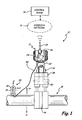
- FIG. 1 shows process control or monitoring system 10, which includes pressure transmitter 12, control room 14, wireless network 16, process fluid conduit or pipeline 18, and adjustable resonance frequency vibration power harvester 20.
- Pressure transmitter 12 includes pressure sensor 22 for sensing the pressure level of a process fluid within pipeline 18, and transmitter circuitry 24 for transmitting electrical signals generated by pressure sensor 22 over wireless network 16 to control room 14 with antenna 25, or to local display 26, or both.
- Pressure transmitter 12 is connected to pipeline 18 with various connection devices, such as flange 28 and manifold 30, which enable a fluid connection between hydraulic system 32 of transmitter 12 and either side of orifice plate 34 of pipeline 18.
- pressure sensor 22 is able to sense a pressure differential within the process fluid across orifice plate 34 to provide a measurement of flow.
- Control room 14 receives data from transmitter 12 and transmits data to transmitter 12.
- Transmitter circuitry 24 includes components for conditioning the output of sensor 22. Based on the processed pressure signal received from circuitry 24 and transmitter 12, control room 14 is able to adjust process parameters either through wireless network 16 or another control loop. For example, control room 14 can adjust the flow of the process fluid through pipeline 18 by adjusting appropriate valves. Transmitter circuitry 24 includes wireless communication components such as a transceiver, so that pressure transmitter 12 can operate over a wireless mesh network using an applicable mesh network protocol. Power for communicating over wireless network 16 and powering electronics 24 is delivered to transmitter 12 with adjustable resonance frequency vibration power harvester 20. Power harvester 20 comprises elongate body 36, cover 38 and power cable 40, which connects power harvester 20 to transmitter circuitry 24 within transmitter 12.
- Power harvester 20 is mounted to pipeline 18 and includes mechanical energy harvesting devices for converting vibration of pipeline 18 into electrical power. In other embodiments, power harvester 20 is mounted directly to process transmitter 12.
- Pipeline 18 is subjected to positive and negative vibratory forces V+ and V- (as well as other three dimensional forces) during operation of control system 10, which causes small, localized displacement of harvester 20 in the X any Y directions (as well as other directions) as pipeline 18 vibrates.
- the localized displacement of harvester 20 is oscillatory in nature such that harvester 20 vibrates at some frequency.
- Harvester 20 undergo repeated, small displacements that are converted to mechanical energy.
- Harvester 20 also includes means for adjusting its mechanical features to induce it to resonance vibration. At resonance vibration, harvester 20 tends to vibrate at the frequency that induces the maximum localized displacement of the energy harvesting devices. Thus, the energy harvesting devices are more effectively able to reap electrical energy from the mechanical movement of pipeline 18.
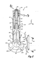
- FIG. 2 shows a first embodiment of adjustable resonance frequency vibration power harvester 20 with cover 38 removed to reveal the components of power harvester 20.
- Power harvester 20 comprises elongate body 36, power harvester devices 42 and 44, weight 46, base 50 and circuitry 52.
- Elongate body 36 comprises first end 54, second end 56, midspan portion 58, harvester openings 61 and 63, and circuitry openings 60 and 62.
- Second end 56 of elongate body 36 is connected to base 50, which comprises a flange for connecting harvester 20 to pipeline 18, transmitter 12 or another vibration source.
- Base 50 preferably includes notches 64A - 64D for receiving threaded fasteners or some other such means for mounting harvester 20.
- Base 50 can be made of any material rigid enough to efficiently transmit vibration from the vibration source to elongate body 36, such as metal, plastic, or composite.
- Base 50 is attached to elongate body 36 with a threaded fastener.
- Elongate body 36 comprises a beam that generally extends perpendicularly from base 50 at second end 56 such that first end 54 is cantilevered.
- elongate body 36 comprises a square beam, but in other embodiment, elongate body 36 may be circular, rectangular, or some other cross-sectional shape.
- First end 54, second end 56 and midspan portion 58 include a circular, interior passageway 65 so that weight 46 and other vibration altering features can be incorporated into elongate body 36.
- Each face of square elongate body 36 preferably includes two openings, such as openings 60 and 61 or openings 62 and 63, that intersect with passageway 65 of elongate body 36 to receive vibration harvester devices or any associated electronics.
- Openings 61 and 63 receive energy harvester devices 42 and 44, and opening 60 receives circuitry 52. Screw holes are provided at either end of each opening such that energy harvester devices or electronics can be mounted to elongate body 36.
- screws 66 are inserted into holes 68 such that printed circuit board 70 upon which circuitry 52 are affixed can be mounted flush to elongate body 36 with circuitry 52 being inside elongate body 36.
- harvester device 42 is mounted to elongate body 36 with screws 71.
- Harvester device 42 is mounted with a plurality of screws 71 at each end to ensure that harvester device 42 is immobilized with respect to elongate body 36 such harvester device 42 and first end 54 vibrate together.
- Energy harvester device 42 is suspended over opening 61 and energy harvester device 44 is suspended over opening 63 such that they are free to flex into and out of elongate body 36 as harvester 20 vibrates when mounted to pipeline 18 ( FIG. 1 ) or some other such vibration source.
- Energy harvesting devices 42 and 44 comprise devices that convert mechanical energy to electrical energy.
- devices 42 and 44 comprise piezoelectric energy harvesting devices. Suitable piezoelectric energy harvesting devices are available commercially, such as from Mide Technology Corporation, Medford, Massachusetts.
- devices 42 and 44 comprise electromagnetic harvesting devices. Suitable electromagnetic energy harvesting devices are available commercially, such as from Perpetuum Limited, Victoria, England. Additionally, suitable vibration power energy devices are available from the present assignee of this application.
- Circuitry 52 includes power cable 40 for connecting circuitry 52 with transmitter 12 ( FIG. 1 ) and input cable 72 for connecting circuitry 52 with energy harvesting device 42.
- Circuitry 52 and printed circuit board 70 include electronics for processing output of energy harvesting devices 42 and 44, such as rectifiers, capacitors, and DC or AC converters.
- Energy harvester devices 42 and 44 are mounted to adjacent faces of elongate body 36 such that they are juxtaposed ninety degrees to each other.
- energy harvester device 42 can be configured for harvesting vibration energy of elongate body 36 in, for example, the X direction
- energy harvester device 44 can be configured for harvesting vibration energy of elongate body 36 in, for example, the Y direction.
- energy harvesting devices 42 and 44 can be configured to harvest energy in other directions, such as the Z direction, or in the same direction.
- energy harvesting devices 42 and 44 are both configured to harvest energy in the same direction such that power harvesting in one direction can be increased.
- Output of energy harvesting devices 42 and 44 can be stacked before being converted to AC or DC current at circuitry 52.
- the means for adjusting the mechanical features of elongate body, such as weight 46 are adjusted to induce resonance frequency vibration of elongate body 36 in a desired direction to increase output of energy harvester devices 42 and 44.
- first end 54 Because elongate body 36 is cantilevered at base 50, movement of second end 56 from the vibration source is transmitted to first end 54.
- the movement, or deflection, of first end 54 is directly related to the frequency at which the vibration source vibrates and the natural frequency of elongate body 36. Movement of first end 54 is controlled by the length of elongate body 36, the resulting force applied to elongate body 36 during vibration, the elasticity of elongate body 36, and the mass of elongate body 36. These parameters can be altered or manipulated to change the natural frequency of elongate body 36 in order to induce resonance frequency vibration of elongate body 36.
- Power harvester 20 of the present invention in its various embodiments presented in FIG. 2 through FIG.
- FIG. 5 includes features for adjusting the frequency of vibration of elongate body 36.
- FIG. 2 shows elongate body 36 having weight 46 attached to first end 54 at passageway 65 within elongate body 36. Additional internal features are included within interior passageway 65 to further adjust the vibration frequency of elongate body 36, which are better illustrated in the cross section of FIG. 3 .
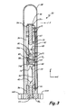
- FIG. 3 shows a cross sectional view of adjustable resonant frequency vibration power harvester 20 as taken at section 3 - 3 of FIG. 2 .
- power harvester 20 includes vibration energy power harvester device 42, weight 46, elongate body 36, base 50, circuitry 52, fastener 73, adjustment weights 74A and 74B and weight 75.
- Elongate body 36 includes first end 54, second end 56 and midspan portion 58. Second end 56 is connected to base 50 with fastener 73.
- Base 50 is mounted to a vibration source, such as pipeline 18 ( FIG. 1 ), at notches 64A and 64C. Movement of the vibration source is transmitted through base 50 to second end 56, midspan portion 58 and first end 54.
- a vibration source such as pipeline 18 ( FIG. 1 )
- first end 54 undergoes an oscillatory displacement at the frequency of the vibration source.
- Weight 46 and adjustment weights 74A and 74B are adjusted to tune the natural frequency of elongate body 36 to match that of the frequency of the vibration source such that elongate body 36 vibrates at resonance.
- First end 54 is situated at an end of passageway 65 and includes a threaded bore for receiving weight 46.
- Weight 46 is secured to first end 54 with, for example, threaded nut 76, which locks weight 46 into passageway 65.
- Weight 46 is placed at the distal end of elongate body 36 furthest away from base 50 and the vibration source to increase the displacement of first end 54 during vibration.
- deflection d of a uniform, cantilevered beam is proportional to length l of the beam and force F applied to the free end of the beam, wherein E is the elastic modulus of the beam and I is the moment of inertia of the beam.
- d F ⁇ l 3 3 ⁇ EI
- first end 54 a greater deflection of first end 54 can be caused by increasing the force applied to the free end during vibration.
- the force applied to the free end, first end 54 is increased by increasing the momentum at first end 54.
- the mass of weight 46 applies an oscillating force +/- F at first end 54 proportional to the acceleration imparted to first end 54 by the vibration source, according to equation (2).
- the force of weight 46 causes a greater deflection of first side surface as is shown with equation (1), which affects the vibrational amplitude and frequency of first end 54.
- the mass and length of weight 46 can be selected to produce resonance vibration in elongate body 36 based on the induced vibration in elongate body 36 by the vibration source to maximize output of vibration power harvesters 42 and 44.
- Equation (3) illustrates the relationship between the elastic modulus E, force F, initial length L 0 , initial cross-sectional area A 0 and change in length ⁇ L of a uniform body in tension.
- Adjustable weights 74A and 74B comprise set screws that are threaded into passageway 65.
- adjustable weights 74A and 74B comprise cylindrical plugs or disks.
- adjustable weights 74A and 74B may comprise other shapes.
- Passageway 65 comprises a circular bore extending from first end 54 to second end 56. Near first end 54 and second end 56, and at midspan portion 58, elongate body 36 completely surrounds passageway 65. However, near openings 60 - 63 (See FIG. 2 ) elongate body 36 only bounds passageway 65 at its four corners, thus resulting in elongate body 36 having a non-uniform cross section.
- Passageway 65 is sized to accept weight 46, however, in other embodiments, the diameters of weight 46, weights 74A and 74B and passageway 65 are adjusted to meet specific design needs.
- Adjustable weights 74A and 74B include threads for engaging mating threads along passageway 65.
- Passageway 65 extends through elongate body 36 such that weight 46 is placed at first end 54 and adjustable weights 74A and 74B can be adjustably positioned along the length of elongate body 36.
- Adjustable weights 74A and 74B include sockets 80 for receiving a tool for rotating weights 74A and 74B within passageway 65.
- Weights 74A and 74B are adjusted within passageway 65 such that they abut each other and produce localized strain ⁇ l in the walls of elongate body 36 near where weight 74A and weight 74B meet. Weights 74A and 74B operate similar to that of jam nuts, wherein a first weight is threaded into a position within passageway 65 where the localized strain is desired to be produced, and then the second weight is threaded up against the first and torqued down. As the weights are pressed together, their threaded engagement with elongate body 36 puts the walls of elongate body 36 into tension. Thus, as described above with reference to equations (1) and (3), the displacement of first end 54 is affected during vibration.
- the position of the localized strain ⁇ l is selected to induce resonance vibration of elongate body 36 for the given vibration frequency of the vibration source. Similar to that of weight 46, the mass of weights 74A and 74B influence the vibration of elongate body 36. Thus, the material of weights 74A and 74B and weight 46 can be selected to produce the desired impact on the vibration of elongate body 36. The mass and positions of weights 46, 74A and 74B are adjusted to bring elongate body 36 into resonance frequency to increase the displacement of first end 54 and harvester device 42. As such, the energy harvested by device 42 is maximized for the given frequency generated by the vibration source.
- the local displacement of harvester device 42 within opening 63 can also be increased to further increase the energy available for harvesting.
- Weight 75 is placed along the midspan portion of harvester device 42 to increase the localized deflection of device 42. Just as weight 46 increases the deflection of elongate body 36 due to the imparted forces of the vibration source, weight 75 uses the acceleration generated by the vibration source to increase deflection of harvester device 42. Also, the size and mass of weight 75 is selected to produce resonance vibration of harvester device 42 based on the frequency input of the vibration source. Accordingly, the output of harvester device 42 is increased by increasing the absolute and relative displacement of device 42 with weights 46 and 75, and weights 74A and 74B.
- first weight 74A and second weight 74B produce a discontinuity in elongate body 36, producing a two-stage beam with segments having different natural frequencies of vibration.
- elongate body 36 is non-uniform in that the weights 46, 74A and 74B and openings 60 - 63 produce, for example, mass discontinuities along elongate body 36.
- the deflection of a cantilevered beam depends on the mass of the beam, the length of the beam and the elasticity of the beam as is shown in equations (1), (2) and (3). Equations (1), (2) and (3) are, however, directed to beams having uniform properties.
- Beams having non-uniform properties adds further complexity to equations (1), (2) and (3), but are still affected by the length, mass and elasticity of the beam.
- the length, weight mass and non-uniformity of a beam determine the natural frequency of the beam.
- the natural frequency ⁇ n of a beam having a first segment having length L 1 and a second segment having length L 2 is affected by the elastic modulus E of the beam, the mass m of the beam, and the moment of inertia of the first segment I l , as shown in equation (4).
- f n 1 2 ⁇ ⁇ ⁇ 3 ⁇ EI I m ⁇ L 1 + L 2 2 3
- equations (1) through (4) show that the natural frequency of a non-uniform beam can be altered by (a) changing the mass of the beam such as by adding weight 46 or by (b) changing the elastic modulus E of the beam such as by altering the strain ⁇ l in elongate body 36 with weights 74A and 74B. Equations (1) through (4) also show that the natural frequency of a non-uniform beam can be altered by (c) changing the length of at least one segment of the non-uniform beam, or by (d) changing the distribution of the mass along the length of the beam, which are illustrated in FIGS. 4 and 5 .
- FIG. 4 shows a perspective view of a second embodiment of adjustable resonance frequency vibration power harvester 20 of FIG. 1 .
- elongate body 36 of power harvester 20 includes elongate weight 82 and cantilevered harvesting devices 84 and 86.
- Elongate body 36 which is mounted to base 50, comprises similar components as shown in FIGS. 2 and 3 , including first end 54, second end 56, midspan 58 and passageway 65.
- Elongate body 36 also includes openings 87A and 87B, which are similar to openings 60 and 62 of the embodiment of elongate body 36 shown in FIGS. 2 and 3 . Openings 87A and 87B, however, do not extend through to interior passageway 65.
- Elongate body 36 is connected to base 50 with fastener 73, and base 50 is connected with a vibration source such as pipeline 18, as is done with base 50 of FIG. 2 , to induce movement of first end 54 in the X, Y and Z directions.
- Circuitry 52 is mounted on printed circuit board 70 using bores 68 and threaded fasteners 66. Circuitry 52 is mounted to elongate body 36 such that circuitry 52 faces away from opening 87A.
- Cantilevered harvesting devices 84 and 86 are connected to elongate body with threaded fasteners 71 such that the free ends of devices 84 and 86 are able to vibrate alongside elongate body 36.
- Cantilevered devices 84 and 86 also include weights 88 and 90, respectively, to increase the deflection of devices 84 and 86 as elongate body 36 vibrates. Similar to that of weight 75, the size and mass of weights 88 and 90 are selected such that devices 84 and 86 vibrate at resonance, thus maximizing the energy harvested for each oscillation of elongate body 36.
- Power harvester 20 also includes elongate weight 82 that is used to tune the vibration of elongate body 36.
- Elongate weight 82 increases the length of elongate body 36 to adjust the vibration characteristics of elongate body 36.
- Elongate weight 82 also displaces weight along the length of elongate body 36 to adjust the vibration characteristics of elongate body 36.
- Elongate weight 82 includes graduation marks indicating different distances along the length of elongate weight 82. The graduation marks can be used to indicate, for example, the distance elongate weight 82 extends beyond first side surface 84, the mass extending beyond first side surface 82, or the frequency of elongate body 36.
- Power harvester 20 also includes internal weight 92 traversable along passageway 65 to tune the frequency of elongate body 36, as is shown in FIG. 5 .
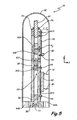
- FIG. 5 shows a cross sectional view of adjustable resonance frequency vibration power harvester 20 as taken at section 5 - 5 of FIG. 4 .
- Power harvester 20 includes weights 92A, 92B, 92C and 92D, which provide localized tension of elongate body 36 to adjust the natural frequency of elongate body 36.
- Energy harvesting device 86 is secured to elongate body 36 with threaded fasteners 71 at only one end. As such, device 86 is suspended over elongate body 36 and is free to vibrate.
- Harvesting device 86 includes weight 90 that enhances the vibration of device 86 during operation, thus inducing greater deflection of device 86.
- Power harvester 20 is also provided with stopper 94, which is embedded within a notch in elongate body 36.
- Stopper 94 which in one embodiment comprises a rubber pad, dampens the vibration of harvesting device 86, thus preventing over-deflection and damage of harvesting device 86.
- interior passageway 65 extends from first end 54 to second end 56.
- internal frequency adjusting components such as weights 82 and 92A - 92D, are free to traverse the length of elongate body 36 without interference from circuitry 52.
- Elongate weight 82 extends into passageway 65 at first end 54, but also extends beyond first end 54.
- Elongate weight 82 includes threads to engage with threads in passageway 65 such that the position of elongate weight 82 along elongate body 36 can be adjusted.
- Elongate weight 82 has a mass that is extended out from first end 54 to extend the effective length of elongate body 36 and to change the mass distribution along elongate body 36.
- the length of elongate weight 82 is selected to permit a desired mass to extend beyond first end 54, but is selected based on design needs and the geometry of elongate body 36.
- the density of elongate weight 82 can be selected such that the weight of a unit length of elongate weight 82 matches the weight of a unit length of elongate body 36.
- the position of elongate weight 82 is secured within interior passageway 65 with lock nut 76.
- elongate body 36 also includes internal weights 92A-92D. Additionally, weights 92A - 92D comprise two sets of tensioning weights to induce two separate strain variations in elongate body 36.
- weights 92A - 92D can be used independently within passageway 65 to increase deflection of elongate body in a manner similar to that of weight 82.
- the density of elongate body 36 can be varied from first end 54 to second end 56 to aid in adjusting the resonance vibration frequency of elongate body 36 to resonance.
- the length of elongate body 36 is increased to increase the deflection at first end 54 during vibration [as is illustrated by variable l of equation (1), or variable L 2 of equation (4)], thus adjusting the natural frequency of elongate body 36 by method (c) described above.
- the position and mass of elongate weight 82 can be adjusted to increase or decrease the force F applied to first end 54 [as is illustrated by variable F of equation (2) and variable d in equation (1)], thus adjusting the natural frequency of elongate body 36 by methods (a) and (d) above.
- Internal weights 92A - 92D which are used to adjust the vibrational frequency of elongate body 36 in a similar fashion to that of weights 74A and 74B of FIGS. 2 and 3 by producing local strain ⁇ 2 in the walls of elongate body 36 [as is illustrated by elasticity E in equation (3)], thus adjusting the natural frequency of elongate body 36 by method (b) above.
- Weights 46, 74A, 74B, 82 and 92A - 92D comprise various features and means for adjusting the mechanical properties of elongate body 36 to induce resonance vibration of elongate body 36 when subjected to vibration from a vibration source. Typically, only one such feature would be necessary to induce resonance vibration in elongate body 36. However, each specific feature can be used alone or in conjunction with others. For example, one feature can be used to enhance vibration in one direction, while another feature is used to dampen vibration in an opposite direction in order to further maximize deflection in the first direction. In other embodiments, the vibration adjusting features, such as weights 46, 74A, 74B, 82 and 92A - 92D, can be modified as is needed for specific applications.
- elongate body 36 and weights 46, 74A, 74B, 82 and 92A - 92D can be selected based on design needs, as is dictated by the amount of power desired to be harvester and the frequency of the vibration source. Also, the number of vibration energy power harvesters can be adjusted.
- elongate beam 36 includes openings, such as openings 61 and 63, for four vibration energy power harvesters, one on each side of elongate beam 36. In other embodiments, however, the length of elongate beam 36 can be increased such as to include space for additional openings in elongate beam 36.
- the resonance frequency for elongate body 36 can be determined, either mathematically or experimentally through trial and error. Accordingly, look-up tables correlating the frequency of the vibration source to the resonance frequency of elongate body 36 can be compiled and stored either in a reference manual or within transmitter electronics 24. Likewise, the graduation marks on elongate weight 82 can be inscribed with appropriate information for adjusting elongate body 36 to resonance. Although elongate body 36 is depicted as including multiple frequency adjusting devices, any one or combination of them may be used based on design needs. Thus, the power generated by vibration harvesting devices 42, 44, 84 and 86 can be maximized for a particular vibration of the vibration source.
Landscapes
- Apparatuses For Generation Of Mechanical Vibrations (AREA)
- General Electrical Machinery Utilizing Piezoelectricity, Electrostriction Or Magnetostriction (AREA)
- Vibration Prevention Devices (AREA)
Claims (15)
- Resonanzfrequenzschwingungsenergieaufnehmer, Folgendes umfassend:einen flexiblen, langgestreckten Körper mit:einem ersten Ende;einem zweiten Ende zum Anschließen an eine Schwingungsquelle, und zwar so,dass das erste Ende auskragt; undeiner ersten Schwingungsenergieaufnehmervorrichtung, die angrenzend an das erste Ende des langgestreckten Körpers angebracht ist, um Energie aufzunehmen, wenn der flexible, langgestreckte Körper schwingt, dadurch gekennzeichnet, dass der langgestreckte Körper einen mit Gewinde versehenen und zylindrischen Innenkanal besitzt, der sich durch zumindest einen Abschnitt des langgestreckten Körpers zwischen dem ersten Ende und dem zweiten Ende erstreckt; undeinem zylindrischen Gewicht, das an einer festen Position in den Innenkanal eingeschraubt ist, um eine Resonanzfrequenz des langgestreckten Körpers einzustellen.
- Resonanzfrequenzschwingungsenergieaufnehmer nach Anspruch 1, wobei das Gewicht einen langgestreckten, mit Gewinde versehenen Zylinder für durchquerende Gewindeeingriffe im Innenkanal umfasst,
wobei sich der langgestreckte, mit Gewinde versehene Zylinder vorzugsweise teilweise aus dem Innenkanal über das erste Ende hinaus erstreckt, um die Gesamtwirkungslänge des langgestreckten Körpers zu erhöhen, oder
wobei der langgestreckte, mit Gewinde versehene Zylinder darüber hinaus Graduierungsmarkierungen aufweist. - Resonanzfrequenzschwingungsenergieaufnehmer nach Anspruch 1, wobei das Gewicht eine erste mit Gewinde versehene Feststellschraube für durchgehende Gewindeeingriffe im Innenkanal umfasst,
wobei die mit Gewinde versehene Feststellschraube vorzugsweise im Innenkanal versenkt ist, um die auf mittlerer Spannweite befindliche Masse des langgestreckten Körpers einzustellen. - Resonanzfrequenzschwingungsenergieaufnehmer nach Anspruch 3, darüber hinaus eine zweite mit Gewinde versehene Scheibe umfassend, die im Innenkanal versenkt ist, und wobei die erste mit Gewinde versehene Scheibe und die zweite mit Gewinde versehene Scheibe aneinander anstoßen, um eine lokale Belastung des langgestreckten Körpers angrenzend an die erste und zweite Scheibe einzustellen.
- Resonanzfrequenzschwingungsenergieaufnehmer nach Anspruch 4, darüber hinaus eine dritte und vierte mit Gewinde versehene Scheibe umfassend, die im Innenkanal versenkt sind, wobei die dritte und vierte mit Gewinde versehene Scheibe aneinander anstoßen, um eine lokale Belastung des langgestreckten Körpers angrenzend an die dritte und vierte Scheibe einzustellen, und zwar so, dass der langgestreckte Körper mehrere induzierte Belastungsveränderungen aufweist.
- Resonanzfrequenzschwingungsenergieaufnehmer nach Anspruch 1, darüber hinaus eine zweite Schwingungsenergieaufnehmervorrichtung umfassend, die angrenzend an das erste Ende des langgestreckten Körpers angebracht ist, und zwar so, dass die erste und zweite Schwingungsenergieaufnehmervorrichtung um neunzig Grad voneinander versetzt sind.
- Resonanzfrequenzschwingungsenergieaufnehmer nach Anspruch 6, wobei der langgstreckte Körper einen quadratischen Querschnitt hat und die erste und zweite Schwingungsenergieaufnehmervorrichtung an verschiedenen Flächen des langgestreckten Körpers montiert sind,
wobei vorzugsweise die erste Schwingungsenergieaufnehmervorrichtung entlang des langgestreckten Körpers ausgerichtet ist, um Energie in einer ersten Richtung aufzunehmen, und die zweite Schwingungsenergieaufnehmervorrichtung entlang des langgestreckten Körpers ausgerichtet ist, um Energie in einer zweiten Richtung aufzunehmen, und zwar so, dass die erste Schwingungsenergieaufnehmervorrichtung Energie in einer x-Richtung aufnimmt, und die zweite Schwingungsenergieaufnehmervorrichtung Energie in einer y-Richtung auf-nimmt, oder
wobei die erste Schwingungsenergieaufnehmervorrichtung und die zweite Schwingungsenergieaufnehmervorrichtung ausgerichtet sind, um Energie in einer Schwingungsrichtung des langgestreckten Körpers aufzunehmen, und zwar so, dass die erste und zweite Schwingungsenergieaufnehmervorrichtung Energie in einer x-Richtung aufnehmen. - Resonanzfrequenzschwingungsenergieaufnehmer nach Anspruch 1, darüber hinaus eine Öffnung im langgestreckten Körper angrenzend an die erste Schwingungsenergieaufnehmervorrichtung aufweisend,
wobei vorzugsweise die erste Schwingungsenergieaufnehmervorrichtung aufweist:ein erstes Ende, das fest am langgestreckten Körper angrenzend an die Öffnung angebracht ist; undein zweites Ende, das nicht am langgestreckten Körper angebracht ist und über der Öffnung hängt, so dass die erste Schwingungsenergieaufnehmervorrichtung über der Öffnung auskragt und ein Gewicht umfasst, das an einem freien Ende der ersten Schwingungsenergieaufnehmervorrichtung positioniert ist, und darüber hinaus vorzugsweise mechanische Anschläge aufweisend, um die Bewegung der einseitig aufgehängten Schwingungsenergieaufnehmervorrichtung einzuschränken. - Resonanzfrequenzschwingungsenergieaufnehmer nach Anspruch 1, wobei die Dichte des langgestreckten Körpers vom ersten Ende zum zweiten Ende variiert.
- Resonanzfrequenzschwingungsenergieaufnehmer nach Anspruch 1, wobei die erste Schwingungsenergieaufnehmervorrichtung einen elektromagnetischen oder einen piezoelektrischen Generator umfasst.
- Resonanzfrequenzschwingungsenergieaufnehmer nach Anspruch 1, darüber hinaus eine Öffnung im langgestreckten Körper aufweisend, um Schaltungen aufzunehmen, während es dem Gewicht erlaubt ist, den langgestreckten Körper zu durchqueren.
- Resonanzfrequenzschwingungsenergieaufnehmer nach Anspruch 11, wobei:der Resonanzfrequenzschwingungsenergieaufnehmer darüber hinaus umfasst:Aufnehmerschaltungen, die in der Öffnung positioniert sind; undein erstes Kabel, um die erste Schwingungsenergieaufnehmervorrichtung mit den Aufnehmerschaltungen zu verbinden; unddie Schwingungsquelle ein industrielles Prozesssteuerungssystem umfasst, das eine Leitung und einen Prozess-Transmitter enthält, wobei der Prozess-Transmitter umfasst:einen Sensor zum Abfühlen eines Parameters, der aus der Gruppe ausgewählt ist, die aus Druck, Temperatur, Pegel und Durchfluss eines Prozessfluids in der Leitung besteht, und zum Generieren eines Sensorsignals, das vom abgefühlten Parameter abhängt;eine Transmitterelektronik, die an den Sensor angeschlossen ist, wobei die Transmitterelektronik das Sensorsignal konditioniert, um einen Transmitterausgang zu erzeugen, der für den abgefühlten Parameter repräsentativ ist, wobei die Transmitterelektronik in der Lage ist, über eine externe Regelschleife zu kommunizieren; undein Energiekabel, das die Aufnehmerschaltungen so an die Transmitterelektronik anschließt, dass die erste Schwingungsenergieaufnehmervorrichtung Energie an die Transmitterelektronik und den Sensor liefert.
- Verfahren zum Einstellen einer Frequenz einer Schwingungsenergieaufnehmervorrichtung, wobei das Verfahren umfasst:Montieren einer Schwingungsenergieaufnehmervorrichtung angrenzend an ein erstes Ende eines Auslegers;Montieren eines zweiten Endes des Auslegers an einer Schwingungsquelle, und zwar so, dass die Schwingungsenergieaufnehmervorrichtung von der Schwingungsquelle auskragt;Einstellen einer Position einer ersten Masse innerhalb des Auslegers, bis der Ausleger bei Resonanz schwingt.
- Verfahren zum Einstellen einer Frequenz einer Schwingungsenergieaufnehmervorrichtung nach Anspruch 13, wobei der Schritt des Einstellens der Position der ersten Masse innerhalb des Auslegers umfasst, die erste Masse sich teilweise über das erste Ende des Auslegers hinaus erstrecken zu lassen.
- Verfahren zum Einstellen einer Frequenz einer Schwingungsenergieaufnehmervorrichtung nach Anspruch 13, wobei der Schritt des Einstellens der Position der ersten Masse innerhalb des Auslegers umfasst, die erste Masse vollständig innerhalb des Auslegers zum Eingriff mit einer zweiten Masse zu versenken und eine lokale Belastung innerhalb des Auslegers angrenzend an die erste und zweite Masse zu erzeugen.
Applications Claiming Priority (2)
| Application Number | Priority Date | Filing Date | Title |
|---|---|---|---|
| US12/012,900 US7812466B2 (en) | 2008-02-06 | 2008-02-06 | Adjustable resonance frequency vibration power harvester |
| PCT/US2009/000782 WO2009099658A2 (en) | 2008-02-06 | 2009-02-06 | Adjustable resonance frequency vibration power harvester |
Publications (3)
| Publication Number | Publication Date |
|---|---|
| EP2250682A2 EP2250682A2 (de) | 2010-11-17 |
| EP2250682A4 EP2250682A4 (de) | 2012-09-12 |
| EP2250682B1 true EP2250682B1 (de) | 2014-04-09 |
Family
ID=40931042
Family Applications (1)
| Application Number | Title | Priority Date | Filing Date |
|---|---|---|---|
| EP09709384.3A Active EP2250682B1 (de) | 2008-02-06 | 2009-02-06 | Vibrationsenergiegewinnungsvorrichtung mit justierbarer resonanzfrequenz |
Country Status (5)
| Country | Link |
|---|---|
| US (1) | US7812466B2 (de) |
| EP (1) | EP2250682B1 (de) |
| JP (1) | JP5504177B2 (de) |
| CN (1) | CN101939861B (de) |
| WO (1) | WO2009099658A2 (de) |
Families Citing this family (41)
| Publication number | Priority date | Publication date | Assignee | Title |
|---|---|---|---|---|
| AU2002950754A0 (en) | 2002-08-09 | 2002-09-12 | Cochlear Limited | Mechanical design for a cochlear implant |
| AU2002950755A0 (en) | 2002-08-09 | 2002-09-12 | Cochlear Limited | Fixation system for a cochlear implant |
| US8538560B2 (en) | 2004-04-29 | 2013-09-17 | Rosemount Inc. | Wireless power and communication unit for process field devices |
| US8145180B2 (en) | 2004-05-21 | 2012-03-27 | Rosemount Inc. | Power generation for process devices |
| US7913566B2 (en) | 2006-05-23 | 2011-03-29 | Rosemount Inc. | Industrial process device utilizing magnetic induction |
| US7626316B2 (en) * | 2007-09-28 | 2009-12-01 | Robert Bosch Gmbh | Passive self-tuning resonator system |
| US8250924B2 (en) * | 2008-04-22 | 2012-08-28 | Rosemount Inc. | Industrial process device utilizing piezoelectric transducer |
| US8222754B1 (en) * | 2008-05-28 | 2012-07-17 | Arjae Spectral Enterprises Ltd. | Vibration-based power generator |
| US8694060B2 (en) | 2008-06-17 | 2014-04-08 | Rosemount Inc. | Form factor and electromagnetic interference protection for process device wireless adapters |
| CN102067048B (zh) | 2008-06-17 | 2017-03-08 | 罗斯蒙特公司 | 用于具有可变压降的现场设备的rf适配器 |
| US8929948B2 (en) | 2008-06-17 | 2015-01-06 | Rosemount Inc. | Wireless communication adapter for field devices |
| CN102084307B (zh) | 2008-06-17 | 2014-10-29 | 罗斯蒙特公司 | 用于具有低压本质安全钳的现场设备的rf适配器 |
| US7977924B2 (en) * | 2008-11-03 | 2011-07-12 | Rosemount Inc. | Industrial process power scavenging device and method of deriving process device power from an industrial process |
| US9674976B2 (en) | 2009-06-16 | 2017-06-06 | Rosemount Inc. | Wireless process communication adapter with improved encapsulation |
| US8626087B2 (en) | 2009-06-16 | 2014-01-07 | Rosemount Inc. | Wire harness for field devices used in a hazardous locations |
| US8258644B2 (en) * | 2009-10-12 | 2012-09-04 | Kaplan A Morris | Apparatus for harvesting energy from flow-induced oscillations and method for the same |
| JP5422676B2 (ja) * | 2010-02-09 | 2014-02-19 | 富士通株式会社 | 圧電発電装置 |
| JP5609244B2 (ja) * | 2010-04-28 | 2014-10-22 | パナソニック株式会社 | 振動発電デバイス |
| US10761524B2 (en) | 2010-08-12 | 2020-09-01 | Rosemount Inc. | Wireless adapter with process diagnostics |
| WO2012039681A1 (en) | 2010-09-22 | 2012-03-29 | National University Of Singapore | Vibration detector and method |
| US10419861B2 (en) | 2011-05-24 | 2019-09-17 | Cochlear Limited | Convertibility of a bone conduction device |
| ITTO20110694A1 (it) | 2011-07-28 | 2011-10-27 | Torino Politecnico | Sistema di infomobilita' e/o diagnostica autoalimentato e dispositivo harvester perfezionato di alimentazione di tale sistema |
| US20130096366A1 (en) | 2011-10-12 | 2013-04-18 | Wim Bervoets | Implantable medical device |
| US9310794B2 (en) | 2011-10-27 | 2016-04-12 | Rosemount Inc. | Power supply for industrial process field device |
| JP5967650B2 (ja) * | 2011-11-14 | 2016-08-10 | 国立大学法人東北大学 | 振動発電装置および振動発電装置の制御方法 |
| GB2515224B (en) * | 2012-03-07 | 2019-04-03 | Baker Hughes Inc | Self-tuning energy harvester |
| US9049527B2 (en) | 2012-08-28 | 2015-06-02 | Cochlear Limited | Removable attachment of a passive transcutaneous bone conduction device with limited skin deformation |
| US9913321B2 (en) * | 2013-01-25 | 2018-03-06 | Energyield, Llc | Energy harvesting container |
| US9188488B2 (en) * | 2013-03-14 | 2015-11-17 | Rosemount Inc. | Vibration detection in thermowells |
| WO2015051172A1 (en) * | 2013-10-02 | 2015-04-09 | Eaton Corporation | Hydraulic system sensor |
| GB201318799D0 (en) * | 2013-10-24 | 2013-12-11 | Piezotag Ltd | Power harvestering assembly |
| CN103986367B (zh) * | 2014-04-28 | 2017-01-11 | 浙江海洋学院 | 压电式能量收集系统 |
| EP3204635B1 (de) * | 2014-10-06 | 2020-05-06 | Vortex Bladeless, S.L. | Elektrischer generator und verfahren zur leistungserzeugung |
| US11012006B2 (en) | 2015-10-19 | 2021-05-18 | Massachusetts Institute Of Technology | Micro electromechanical system (MEMS) energy harvester with residual stress induced instability |
| WO2017174161A1 (en) * | 2016-04-07 | 2017-10-12 | Vortex Bladeless, S.L. | Electrical power generator |
| US10243136B2 (en) * | 2016-08-22 | 2019-03-26 | Masoud Ghanbari | Piezoelectric energy harvesting system from vehicle's tires |
| CN106774487B (zh) * | 2016-12-28 | 2018-11-13 | 珠海格力电器股份有限公司 | 一种避振调节系统及避振调节方法 |
| WO2019060879A1 (en) | 2017-09-25 | 2019-03-28 | Fluid Handling Llc | CONVERTING THE MECHANICAL ENERGY OF AN ELECTRIC POWER VIBRATION FOR POWERING A CIRCUIT BOARD FOR STATUS MONITORING OF ROTARY MACHINES |
| EP3735784A4 (de) * | 2018-01-05 | 2021-10-06 | Weir Slurry Group, Inc. | Drahtloses system zur überwachung der schüttelsiebleistung mittels eines energiegewinnungssystems |
| KR102125405B1 (ko) * | 2018-08-29 | 2020-06-22 | 한국과학기술연구원 | 넓은 동작 주파수 범위를 갖는 자가 공진 조절 압전 에너지 하베스터 |
| US11190113B2 (en) * | 2019-02-07 | 2021-11-30 | Cairdac | Leadless autonomous cardiac capsule with rotatably-mounted piezoelectric energy harvester |
Family Cites Families (34)
| Publication number | Priority date | Publication date | Assignee | Title |
|---|---|---|---|---|
| US3064096A (en) * | 1957-10-30 | 1962-11-13 | Siemens And Halske Ag Berlin A | Contact alternator |
| US3161793A (en) * | 1960-09-13 | 1964-12-15 | Nat Res Dev | Electrical machines involving the reciprocation of moving parts |
| US3581129A (en) * | 1970-06-05 | 1971-05-25 | Messrs Gebruder Junghons Gmbh | Tuning fork devices |
| US3786413A (en) * | 1972-01-13 | 1974-01-15 | Sperry Rand Corp | Vehicle tire condition monitor system |
| FR2314614A1 (fr) * | 1975-06-09 | 1977-01-07 | Jarret Jacques | Alternateur a excitation impulsionnelle |
| US4318016A (en) * | 1980-03-04 | 1982-03-02 | Western Control Equipment Co. | Transducer |
| US4387318A (en) * | 1981-06-04 | 1983-06-07 | Piezo Electric Products, Inc. | Piezoelectric fluid-electric generator |
| US4470121A (en) * | 1981-08-17 | 1984-09-04 | United Technologies Corporation | Multi-frequency vibration controller using fluid-filled cantilever beam for vibration excitation & absorption |
| US4500827A (en) * | 1984-06-11 | 1985-02-19 | Merritt Thomas D | Linear reciprocating electrical generator |
| US4536674A (en) * | 1984-06-22 | 1985-08-20 | Schmidt V Hugo | Piezoelectric wind generator |
| US6809515B1 (en) * | 1998-07-31 | 2004-10-26 | Spinix Corporation | Passive solid-state magnetic field sensors and applications therefor |
| DE10015619A1 (de) * | 2000-03-29 | 2001-10-04 | Endress Hauser Gmbh Co | Programmierbares Feldgerät |
| US6407484B1 (en) * | 2000-09-29 | 2002-06-18 | Rockwell Technologies Inc | Piezoelectric energy harvester and method |
| US7256505B2 (en) * | 2003-03-05 | 2007-08-14 | Microstrain, Inc. | Shaft mounted energy harvesting for wireless sensor operation and data transmission |
| US6835463B2 (en) * | 2002-04-18 | 2004-12-28 | Oakland University | Magnetoelectric multilayer composites for field conversion |
| US6936937B2 (en) * | 2002-06-14 | 2005-08-30 | Sunyen Co., Ltd. | Linear electric generator having an improved magnet and coil structure, and method of manufacture |
| US6858970B2 (en) * | 2002-10-21 | 2005-02-22 | The Boeing Company | Multi-frequency piezoelectric energy harvester |
| US20040150529A1 (en) * | 2003-01-30 | 2004-08-05 | Benoit Jeffrey T. | Power harvesting sensor for monitoring and control |
| US6984902B1 (en) * | 2003-02-03 | 2006-01-10 | Ferro Solutions, Inc. | High efficiency vibration energy harvester |
| US20050087019A1 (en) * | 2003-10-24 | 2005-04-28 | Face Bradbury R. | Self-powered vibration monitoring system |
| JP2005160028A (ja) * | 2003-10-27 | 2005-06-16 | Nec Tokin Corp | 撓み振動型エキサイタ |
| US7161254B1 (en) * | 2004-01-07 | 2007-01-09 | Trimble Navigation Ltd. | Methods and systems for harnessing electrical energy from ambient vibrational motion of a moving vehicle |
| US7224077B2 (en) * | 2004-01-14 | 2007-05-29 | Ocean Power Technologies, Inc. | Bluff body energy converter |
| WO2005069959A2 (en) * | 2004-01-21 | 2005-08-04 | The Regents Of The University Of Michigan | Method and micro power generator for generating electrical power from low frequency vibrational energy |
| US7208845B2 (en) * | 2004-04-15 | 2007-04-24 | Halliburton Energy Services, Inc. | Vibration based power generator |
| US7199480B2 (en) * | 2004-04-15 | 2007-04-03 | Halliburton Energy Services, Inc. | Vibration based power generator |
| WO2006046938A1 (en) * | 2004-10-21 | 2006-05-04 | Societe De Technologie Michelin | A miniaturized piezoelectric based vibrational energy harvester |
| CN101156294B (zh) * | 2005-04-28 | 2010-12-29 | 罗斯蒙德公司 | 现场设备用的充电系统 |
| US7719416B2 (en) * | 2005-09-09 | 2010-05-18 | Microstrain, Inc. | Energy harvesting, wireless structural health monitoring system |
| US7692365B2 (en) * | 2005-11-23 | 2010-04-06 | Microstrain, Inc. | Slotted beam piezoelectric composite |
| US8030807B2 (en) | 2005-12-09 | 2011-10-04 | Chubb International Holdings Limited | Electromechanical energy harvesting system |
| US20080129153A1 (en) | 2006-06-30 | 2008-06-05 | Roundy Shadrach J | Inertial energy scavenger |
| US7541720B2 (en) * | 2006-12-20 | 2009-06-02 | The Boeing Company | Energy harvesting apparatus and method |
| US20080246367A1 (en) * | 2006-12-29 | 2008-10-09 | Adaptivenergy, Llc | Tuned laminated piezoelectric elements and methods of tuning same |
-
2008
- 2008-02-06 US US12/012,900 patent/US7812466B2/en active Active
-
2009
- 2009-02-06 JP JP2010545886A patent/JP5504177B2/ja not_active Expired - Fee Related
- 2009-02-06 EP EP09709384.3A patent/EP2250682B1/de active Active
- 2009-02-06 WO PCT/US2009/000782 patent/WO2009099658A2/en not_active Ceased
- 2009-02-06 CN CN2009801044396A patent/CN101939861B/zh active Active
Also Published As
| Publication number | Publication date |
|---|---|
| CN101939861B (zh) | 2013-11-20 |
| WO2009099658A2 (en) | 2009-08-13 |
| WO2009099658A3 (en) | 2009-10-01 |
| EP2250682A4 (de) | 2012-09-12 |
| JP5504177B2 (ja) | 2014-05-28 |
| CN101939861A (zh) | 2011-01-05 |
| JP2011512777A (ja) | 2011-04-21 |
| EP2250682A2 (de) | 2010-11-17 |
| US7812466B2 (en) | 2010-10-12 |
| US20090195222A1 (en) | 2009-08-06 |
| WO2009099658A4 (en) | 2009-11-12 |
Similar Documents
| Publication | Publication Date | Title |
|---|---|---|
| EP2250682B1 (de) | Vibrationsenergiegewinnungsvorrichtung mit justierbarer resonanzfrequenz | |
| Qi et al. | Design of a multiresonant beam for broadband piezoelectric energy harvesting | |
| Challa et al. | Towards an autonomous self-tuning vibration energy harvesting device for wireless sensor network applications | |
| Lin et al. | The magnetic coupling of a piezoelectric cantilever for enhanced energy harvesting efficiency | |
| US8866316B2 (en) | Tunable vibration energy harvester and method | |
| Lee et al. | Robust segment-type energy harvester and its application to a wireless sensor | |
| US7832281B2 (en) | MEMS-based monitoring | |
| EP2350756B1 (de) | Industrieprozess-stromgewinnungseinrichtung und verfahren zum ableiten von prozesseinrichtungsstrom aus einem industrieprozess | |
| US8011237B2 (en) | Piezoelectric module for energy harvesting, such as in a tire pressure monitoring system | |
| US8358049B2 (en) | Energy converters and associated methods | |
| JP5713916B2 (ja) | 水晶振動子を利用した圧力測定方法および装置 | |
| US20050017602A1 (en) | Shaft mounted energy harvesting for wireless sensor operation and data transmission | |
| US20190025157A1 (en) | Sensorized mechanical component | |
| EP2546544A1 (de) | Schwingungsisolation | |
| CA2404468A1 (en) | Sensor apparatus with two resonant transducers and a single conductor | |
| Shinoda et al. | Acoustic resonant tensor cell for tactile sensing | |
| US7936109B1 (en) | Non-resonant energy harvesting devices and methods | |
| EP0849574A2 (de) | Schwingungsfühler für Druckerdiagnose | |
| Howard et al. | Modal voltages of linear and non-linear structures using distributed artificial neurons | |
| Nastro et al. | Piezoelectric micromachined acoustic transducer with electrically-tunable resonant frequency | |
| KR101729664B1 (ko) | 압전 에너지 하베스팅 시스템 및 상기 압전 에너지 하베스팅 시스템의 특성 해석 방법 | |
| RU2605503C1 (ru) | Стенд для испытаний упругих элементов виброизоляторов с пьезовибратором | |
| Gani et al. | Active vibration control of a beam with piezoelectric patches: real-time implementation with xPC target | |
| Flicker et al. | Validation of optimised vibration energy harvesters under near operational conditions | |
| Gatti | Practices Involved in Broadband Vibration Energy Harvesting Utilizing Variable-Length Multi-Reed Cantilever Array |
Legal Events
| Date | Code | Title | Description |
|---|---|---|---|
| PUAI | Public reference made under article 153(3) epc to a published international application that has entered the european phase |
Free format text: ORIGINAL CODE: 0009012 |
|
| 17P | Request for examination filed |
Effective date: 20100831 |
|
| AK | Designated contracting states |
Kind code of ref document: A2 Designated state(s): AT BE BG CH CY CZ DE DK EE ES FI FR GB GR HR HU IE IS IT LI LT LU LV MC MK MT NL NO PL PT RO SE SI SK TR |
|
| AX | Request for extension of the european patent |
Extension state: AL BA RS |
|
| DAX | Request for extension of the european patent (deleted) | ||
| A4 | Supplementary search report drawn up and despatched |
Effective date: 20120809 |
|
| RIC1 | Information provided on ipc code assigned before grant |
Ipc: H01L 41/113 20060101AFI20120803BHEP Ipc: H02N 2/18 20060101ALI20120803BHEP |
|
| GRAP | Despatch of communication of intention to grant a patent |
Free format text: ORIGINAL CODE: EPIDOSNIGR1 |
|
| INTG | Intention to grant announced |
Effective date: 20130902 |
|
| GRAS | Grant fee paid |
Free format text: ORIGINAL CODE: EPIDOSNIGR3 |
|
| GRAA | (expected) grant |
Free format text: ORIGINAL CODE: 0009210 |
|
| AK | Designated contracting states |
Kind code of ref document: B1 Designated state(s): AT BE BG CH CY CZ DE DK EE ES FI FR GB GR HR HU IE IS IT LI LT LU LV MC MK MT NL NO PL PT RO SE SI SK TR |
|
| REG | Reference to a national code |
Ref country code: GB Ref legal event code: FG4D |
|
| REG | Reference to a national code |
Ref country code: CH Ref legal event code: EP Ref country code: CH Ref legal event code: NV Representative=s name: FELBER AND PARTNER AG PATENTANWAELTE, CH Ref country code: AT Ref legal event code: REF Ref document number: 661763 Country of ref document: AT Kind code of ref document: T Effective date: 20140415 |
|
| REG | Reference to a national code |
Ref country code: IE Ref legal event code: FG4D |
|
| REG | Reference to a national code |
Ref country code: DE Ref legal event code: R096 Ref document number: 602009023099 Country of ref document: DE Effective date: 20140522 |
|
| REG | Reference to a national code |
Ref country code: AT Ref legal event code: MK05 Ref document number: 661763 Country of ref document: AT Kind code of ref document: T Effective date: 20140409 |
|
| REG | Reference to a national code |
Ref country code: NL Ref legal event code: VDEP Effective date: 20140409 |
|
| REG | Reference to a national code |
Ref country code: LT Ref legal event code: MG4D |
|
| PG25 | Lapsed in a contracting state [announced via postgrant information from national office to epo] |
Ref country code: NO Free format text: LAPSE BECAUSE OF FAILURE TO SUBMIT A TRANSLATION OF THE DESCRIPTION OR TO PAY THE FEE WITHIN THE PRESCRIBED TIME-LIMIT Effective date: 20140709 Ref country code: GR Free format text: LAPSE BECAUSE OF FAILURE TO SUBMIT A TRANSLATION OF THE DESCRIPTION OR TO PAY THE FEE WITHIN THE PRESCRIBED TIME-LIMIT Effective date: 20140710 Ref country code: IS Free format text: LAPSE BECAUSE OF FAILURE TO SUBMIT A TRANSLATION OF THE DESCRIPTION OR TO PAY THE FEE WITHIN THE PRESCRIBED TIME-LIMIT Effective date: 20140809 Ref country code: BG Free format text: LAPSE BECAUSE OF FAILURE TO SUBMIT A TRANSLATION OF THE DESCRIPTION OR TO PAY THE FEE WITHIN THE PRESCRIBED TIME-LIMIT Effective date: 20140709 Ref country code: FI Free format text: LAPSE BECAUSE OF FAILURE TO SUBMIT A TRANSLATION OF THE DESCRIPTION OR TO PAY THE FEE WITHIN THE PRESCRIBED TIME-LIMIT Effective date: 20140409 Ref country code: LT Free format text: LAPSE BECAUSE OF FAILURE TO SUBMIT A TRANSLATION OF THE DESCRIPTION OR TO PAY THE FEE WITHIN THE PRESCRIBED TIME-LIMIT Effective date: 20140409 Ref country code: NL Free format text: LAPSE BECAUSE OF FAILURE TO SUBMIT A TRANSLATION OF THE DESCRIPTION OR TO PAY THE FEE WITHIN THE PRESCRIBED TIME-LIMIT Effective date: 20140409 |
|
| PG25 | Lapsed in a contracting state [announced via postgrant information from national office to epo] |
Ref country code: HR Free format text: LAPSE BECAUSE OF FAILURE TO SUBMIT A TRANSLATION OF THE DESCRIPTION OR TO PAY THE FEE WITHIN THE PRESCRIBED TIME-LIMIT Effective date: 20140409 Ref country code: AT Free format text: LAPSE BECAUSE OF FAILURE TO SUBMIT A TRANSLATION OF THE DESCRIPTION OR TO PAY THE FEE WITHIN THE PRESCRIBED TIME-LIMIT Effective date: 20140409 Ref country code: LV Free format text: LAPSE BECAUSE OF FAILURE TO SUBMIT A TRANSLATION OF THE DESCRIPTION OR TO PAY THE FEE WITHIN THE PRESCRIBED TIME-LIMIT Effective date: 20140409 Ref country code: PL Free format text: LAPSE BECAUSE OF FAILURE TO SUBMIT A TRANSLATION OF THE DESCRIPTION OR TO PAY THE FEE WITHIN THE PRESCRIBED TIME-LIMIT Effective date: 20140409 Ref country code: ES Free format text: LAPSE BECAUSE OF FAILURE TO SUBMIT A TRANSLATION OF THE DESCRIPTION OR TO PAY THE FEE WITHIN THE PRESCRIBED TIME-LIMIT Effective date: 20140409 Ref country code: SE Free format text: LAPSE BECAUSE OF FAILURE TO SUBMIT A TRANSLATION OF THE DESCRIPTION OR TO PAY THE FEE WITHIN THE PRESCRIBED TIME-LIMIT Effective date: 20140409 |
|
| PG25 | Lapsed in a contracting state [announced via postgrant information from national office to epo] |
Ref country code: PT Free format text: LAPSE BECAUSE OF FAILURE TO SUBMIT A TRANSLATION OF THE DESCRIPTION OR TO PAY THE FEE WITHIN THE PRESCRIBED TIME-LIMIT Effective date: 20140811 |
|
| REG | Reference to a national code |
Ref country code: DE Ref legal event code: R097 Ref document number: 602009023099 Country of ref document: DE |
|
| PG25 | Lapsed in a contracting state [announced via postgrant information from national office to epo] |
Ref country code: EE Free format text: LAPSE BECAUSE OF FAILURE TO SUBMIT A TRANSLATION OF THE DESCRIPTION OR TO PAY THE FEE WITHIN THE PRESCRIBED TIME-LIMIT Effective date: 20140409 Ref country code: CZ Free format text: LAPSE BECAUSE OF FAILURE TO SUBMIT A TRANSLATION OF THE DESCRIPTION OR TO PAY THE FEE WITHIN THE PRESCRIBED TIME-LIMIT Effective date: 20140409 Ref country code: DK Free format text: LAPSE BECAUSE OF FAILURE TO SUBMIT A TRANSLATION OF THE DESCRIPTION OR TO PAY THE FEE WITHIN THE PRESCRIBED TIME-LIMIT Effective date: 20140409 Ref country code: SK Free format text: LAPSE BECAUSE OF FAILURE TO SUBMIT A TRANSLATION OF THE DESCRIPTION OR TO PAY THE FEE WITHIN THE PRESCRIBED TIME-LIMIT Effective date: 20140409 Ref country code: BE Free format text: LAPSE BECAUSE OF FAILURE TO SUBMIT A TRANSLATION OF THE DESCRIPTION OR TO PAY THE FEE WITHIN THE PRESCRIBED TIME-LIMIT Effective date: 20140409 Ref country code: RO Free format text: LAPSE BECAUSE OF FAILURE TO SUBMIT A TRANSLATION OF THE DESCRIPTION OR TO PAY THE FEE WITHIN THE PRESCRIBED TIME-LIMIT Effective date: 20140409 |
|
| PLBE | No opposition filed within time limit |
Free format text: ORIGINAL CODE: 0009261 |
|
| STAA | Information on the status of an ep patent application or granted ep patent |
Free format text: STATUS: NO OPPOSITION FILED WITHIN TIME LIMIT |
|
| 26N | No opposition filed |
Effective date: 20150112 |
|
| PG25 | Lapsed in a contracting state [announced via postgrant information from national office to epo] |
Ref country code: IT Free format text: LAPSE BECAUSE OF FAILURE TO SUBMIT A TRANSLATION OF THE DESCRIPTION OR TO PAY THE FEE WITHIN THE PRESCRIBED TIME-LIMIT Effective date: 20140409 |
|
| REG | Reference to a national code |
Ref country code: DE Ref legal event code: R097 Ref document number: 602009023099 Country of ref document: DE Effective date: 20150112 |
|
| PG25 | Lapsed in a contracting state [announced via postgrant information from national office to epo] |
Ref country code: SI Free format text: LAPSE BECAUSE OF FAILURE TO SUBMIT A TRANSLATION OF THE DESCRIPTION OR TO PAY THE FEE WITHIN THE PRESCRIBED TIME-LIMIT Effective date: 20140409 |
|
| PG25 | Lapsed in a contracting state [announced via postgrant information from national office to epo] |
Ref country code: LU Free format text: LAPSE BECAUSE OF FAILURE TO SUBMIT A TRANSLATION OF THE DESCRIPTION OR TO PAY THE FEE WITHIN THE PRESCRIBED TIME-LIMIT Effective date: 20150206 |
|
| GBPC | Gb: european patent ceased through non-payment of renewal fee |
Effective date: 20150206 |
|
| PG25 | Lapsed in a contracting state [announced via postgrant information from national office to epo] |
Ref country code: MC Free format text: LAPSE BECAUSE OF FAILURE TO SUBMIT A TRANSLATION OF THE DESCRIPTION OR TO PAY THE FEE WITHIN THE PRESCRIBED TIME-LIMIT Effective date: 20140409 |
|
| REG | Reference to a national code |
Ref country code: IE Ref legal event code: MM4A |
|
| REG | Reference to a national code |
Ref country code: FR Ref legal event code: ST Effective date: 20151030 |
|
| PG25 | Lapsed in a contracting state [announced via postgrant information from national office to epo] |
Ref country code: IE Free format text: LAPSE BECAUSE OF NON-PAYMENT OF DUE FEES Effective date: 20150206 Ref country code: GB Free format text: LAPSE BECAUSE OF NON-PAYMENT OF DUE FEES Effective date: 20150206 |
|
| PG25 | Lapsed in a contracting state [announced via postgrant information from national office to epo] |
Ref country code: FR Free format text: LAPSE BECAUSE OF NON-PAYMENT OF DUE FEES Effective date: 20150302 |
|
| PG25 | Lapsed in a contracting state [announced via postgrant information from national office to epo] |
Ref country code: MT Free format text: LAPSE BECAUSE OF FAILURE TO SUBMIT A TRANSLATION OF THE DESCRIPTION OR TO PAY THE FEE WITHIN THE PRESCRIBED TIME-LIMIT Effective date: 20140409 |
|
| REG | Reference to a national code |
Ref country code: CH Ref legal event code: PCAR Free format text: NEW ADDRESS: DUFOURSTRASSE 116, 8008 ZUERICH (CH) |
|
| PG25 | Lapsed in a contracting state [announced via postgrant information from national office to epo] |
Ref country code: HU Free format text: LAPSE BECAUSE OF FAILURE TO SUBMIT A TRANSLATION OF THE DESCRIPTION OR TO PAY THE FEE WITHIN THE PRESCRIBED TIME-LIMIT; INVALID AB INITIO Effective date: 20090206 |
|
| PG25 | Lapsed in a contracting state [announced via postgrant information from national office to epo] |
Ref country code: CY Free format text: LAPSE BECAUSE OF FAILURE TO SUBMIT A TRANSLATION OF THE DESCRIPTION OR TO PAY THE FEE WITHIN THE PRESCRIBED TIME-LIMIT Effective date: 20140409 |
|
| PG25 | Lapsed in a contracting state [announced via postgrant information from national office to epo] |
Ref country code: TR Free format text: LAPSE BECAUSE OF FAILURE TO SUBMIT A TRANSLATION OF THE DESCRIPTION OR TO PAY THE FEE WITHIN THE PRESCRIBED TIME-LIMIT Effective date: 20140409 |
|
| PG25 | Lapsed in a contracting state [announced via postgrant information from national office to epo] |
Ref country code: MK Free format text: LAPSE BECAUSE OF FAILURE TO SUBMIT A TRANSLATION OF THE DESCRIPTION OR TO PAY THE FEE WITHIN THE PRESCRIBED TIME-LIMIT Effective date: 20140409 |
|
| PGFP | Annual fee paid to national office [announced via postgrant information from national office to epo] |
Ref country code: CH Payment date: 20190304 Year of fee payment: 11 |
|
| REG | Reference to a national code |
Ref country code: CH Ref legal event code: PL |
|
| PG25 | Lapsed in a contracting state [announced via postgrant information from national office to epo] |
Ref country code: LI Free format text: LAPSE BECAUSE OF NON-PAYMENT OF DUE FEES Effective date: 20200229 Ref country code: CH Free format text: LAPSE BECAUSE OF NON-PAYMENT OF DUE FEES Effective date: 20200229 |
|
| REG | Reference to a national code |
Ref country code: DE Ref legal event code: R079 Ref document number: 602009023099 Country of ref document: DE Free format text: PREVIOUS MAIN CLASS: H01L0041113000 Ipc: H10N0030300000 |
|
| PGFP | Annual fee paid to national office [announced via postgrant information from national office to epo] |
Ref country code: DE Payment date: 20260121 Year of fee payment: 18 |