EP2250352B1 - Corps en nid d'abeilles comprenant des zones de flexibilité - Google Patents
Corps en nid d'abeilles comprenant des zones de flexibilité Download PDFInfo
- Publication number
- EP2250352B1 EP2250352B1 EP09715097.3A EP09715097A EP2250352B1 EP 2250352 B1 EP2250352 B1 EP 2250352B1 EP 09715097 A EP09715097 A EP 09715097A EP 2250352 B1 EP2250352 B1 EP 2250352B1
- Authority
- EP
- European Patent Office
- Prior art keywords
- honeycomb body
- honeycomb
- honeycomb structure
- points
- connecting points
- Prior art date
- Legal status (The legal status is an assumption and is not a legal conclusion. Google has not performed a legal analysis and makes no representation as to the accuracy of the status listed.)
- Active
Links
- 239000011888 foil Substances 0.000 claims description 35
- 239000002184 metal Substances 0.000 claims description 35
- 238000000746 purification Methods 0.000 claims description 3
- 238000005219 brazing Methods 0.000 claims description 2
- 241000264877 Hippospongia communis Species 0.000 description 91
- 229910000679 solder Inorganic materials 0.000 description 29
- 238000005476 soldering Methods 0.000 description 16
- 239000000463 material Substances 0.000 description 10
- 239000000853 adhesive Substances 0.000 description 4
- 230000001070 adhesive effect Effects 0.000 description 4
- 239000003054 catalyst Substances 0.000 description 4
- 239000011248 coating agent Substances 0.000 description 4
- 238000000576 coating method Methods 0.000 description 4
- 238000002485 combustion reaction Methods 0.000 description 4
- 230000035939 shock Effects 0.000 description 4
- 230000018109 developmental process Effects 0.000 description 3
- 238000010586 diagram Methods 0.000 description 3
- 238000000034 method Methods 0.000 description 3
- 239000002245 particle Substances 0.000 description 3
- 238000004804 winding Methods 0.000 description 3
- 230000015572 biosynthetic process Effects 0.000 description 2
- 230000003197 catalytic effect Effects 0.000 description 2
- 239000000919 ceramic Substances 0.000 description 2
- 238000006243 chemical reaction Methods 0.000 description 2
- 150000001875 compounds Chemical class 0.000 description 2
- 230000007423 decrease Effects 0.000 description 2
- 230000001419 dependent effect Effects 0.000 description 2
- 239000003344 environmental pollutant Substances 0.000 description 2
- 238000005304 joining Methods 0.000 description 2
- 238000004519 manufacturing process Methods 0.000 description 2
- 239000004745 nonwoven fabric Substances 0.000 description 2
- 231100000719 pollutant Toxicity 0.000 description 2
- 239000000843 powder Substances 0.000 description 2
- 230000001133 acceleration Effects 0.000 description 1
- 230000004323 axial length Effects 0.000 description 1
- 230000001914 calming effect Effects 0.000 description 1
- 239000012876 carrier material Substances 0.000 description 1
- 238000004140 cleaning Methods 0.000 description 1
- 239000003086 colorant Substances 0.000 description 1
- 238000010276 construction Methods 0.000 description 1
- 238000001816 cooling Methods 0.000 description 1
- 230000003247 decreasing effect Effects 0.000 description 1
- 238000009792 diffusion process Methods 0.000 description 1
- 238000009826 distribution Methods 0.000 description 1
- 230000005284 excitation Effects 0.000 description 1
- 239000000446 fuel Substances 0.000 description 1
- 238000010438 heat treatment Methods 0.000 description 1
- 238000010348 incorporation Methods 0.000 description 1
- 230000010354 integration Effects 0.000 description 1
- 230000002045 lasting effect Effects 0.000 description 1
- 239000007769 metal material Substances 0.000 description 1
- 239000003863 metallic catalyst Substances 0.000 description 1
- 238000002156 mixing Methods 0.000 description 1
- 230000010349 pulsation Effects 0.000 description 1
- 230000000717 retained effect Effects 0.000 description 1
- 239000007787 solid Substances 0.000 description 1
- 239000004071 soot Substances 0.000 description 1
- 238000007669 thermal treatment Methods 0.000 description 1
- 238000011144 upstream manufacturing Methods 0.000 description 1
Images


Classifications
-
- F—MECHANICAL ENGINEERING; LIGHTING; HEATING; WEAPONS; BLASTING
- F01—MACHINES OR ENGINES IN GENERAL; ENGINE PLANTS IN GENERAL; STEAM ENGINES
- F01N—GAS-FLOW SILENCERS OR EXHAUST APPARATUS FOR MACHINES OR ENGINES IN GENERAL; GAS-FLOW SILENCERS OR EXHAUST APPARATUS FOR INTERNAL COMBUSTION ENGINES
- F01N3/00—Exhaust or silencing apparatus having means for purifying, rendering innocuous, or otherwise treating exhaust
- F01N3/08—Exhaust or silencing apparatus having means for purifying, rendering innocuous, or otherwise treating exhaust for rendering innocuous
- F01N3/10—Exhaust or silencing apparatus having means for purifying, rendering innocuous, or otherwise treating exhaust for rendering innocuous by thermal or catalytic conversion of noxious components of exhaust
- F01N3/24—Exhaust or silencing apparatus having means for purifying, rendering innocuous, or otherwise treating exhaust for rendering innocuous by thermal or catalytic conversion of noxious components of exhaust characterised by constructional aspects of converting apparatus
- F01N3/28—Construction of catalytic reactors
- F01N3/2803—Construction of catalytic reactors characterised by structure, by material or by manufacturing of catalyst support
- F01N3/2807—Metal other than sintered metal
- F01N3/281—Metallic honeycomb monoliths made of stacked or rolled sheets, foils or plates
-
- F—MECHANICAL ENGINEERING; LIGHTING; HEATING; WEAPONS; BLASTING
- F01—MACHINES OR ENGINES IN GENERAL; ENGINE PLANTS IN GENERAL; STEAM ENGINES
- F01N—GAS-FLOW SILENCERS OR EXHAUST APPARATUS FOR MACHINES OR ENGINES IN GENERAL; GAS-FLOW SILENCERS OR EXHAUST APPARATUS FOR INTERNAL COMBUSTION ENGINES
- F01N2260/00—Exhaust treating devices having provisions not otherwise provided for
- F01N2260/10—Exhaust treating devices having provisions not otherwise provided for for avoiding stress caused by expansions or contractions due to temperature variations
-
- F—MECHANICAL ENGINEERING; LIGHTING; HEATING; WEAPONS; BLASTING
- F01—MACHINES OR ENGINES IN GENERAL; ENGINE PLANTS IN GENERAL; STEAM ENGINES
- F01N—GAS-FLOW SILENCERS OR EXHAUST APPARATUS FOR MACHINES OR ENGINES IN GENERAL; GAS-FLOW SILENCERS OR EXHAUST APPARATUS FOR INTERNAL COMBUSTION ENGINES
- F01N2330/00—Structure of catalyst support or particle filter
- F01N2330/02—Metallic plates or honeycombs, e.g. superposed or rolled-up corrugated or otherwise deformed sheet metal
-
- F—MECHANICAL ENGINEERING; LIGHTING; HEATING; WEAPONS; BLASTING
- F01—MACHINES OR ENGINES IN GENERAL; ENGINE PLANTS IN GENERAL; STEAM ENGINES
- F01N—GAS-FLOW SILENCERS OR EXHAUST APPARATUS FOR MACHINES OR ENGINES IN GENERAL; GAS-FLOW SILENCERS OR EXHAUST APPARATUS FOR INTERNAL COMBUSTION ENGINES
- F01N2330/00—Structure of catalyst support or particle filter
- F01N2330/30—Honeycomb supports characterised by their structural details
- F01N2330/44—Honeycomb supports characterised by their structural details made of stacks of sheets, plates or foils that are folded in S-form
-
- Y—GENERAL TAGGING OF NEW TECHNOLOGICAL DEVELOPMENTS; GENERAL TAGGING OF CROSS-SECTIONAL TECHNOLOGIES SPANNING OVER SEVERAL SECTIONS OF THE IPC; TECHNICAL SUBJECTS COVERED BY FORMER USPC CROSS-REFERENCE ART COLLECTIONS [XRACs] AND DIGESTS
- Y02—TECHNOLOGIES OR APPLICATIONS FOR MITIGATION OR ADAPTATION AGAINST CLIMATE CHANGE
- Y02A—TECHNOLOGIES FOR ADAPTATION TO CLIMATE CHANGE
- Y02A50/00—TECHNOLOGIES FOR ADAPTATION TO CLIMATE CHANGE in human health protection, e.g. against extreme weather
- Y02A50/20—Air quality improvement or preservation, e.g. vehicle emission control or emission reduction by using catalytic converters
Definitions
- the present invention relates to a honeycomb body, as used for example for exhaust aftertreatment in motor vehicles.
- a honeycomb body has at least one housing and a honeycomb structure.
- the honeycomb structure in turn has a multiplicity of channels, each of which can flow through the exhaust gas.
- the honeycomb structure is formed with at least one at least partially structured metallic layer, which forms connecting points fixing the honeycomb structure.
- Such honeycomb bodies which are characterized by high internal flexibility, find particular application as a catalyst carrier body and / or particle in exhaust systems of diesel and / or gasoline engines.
- honeycomb bodies in the exhaust gas purification of internal combustion engines have the advantage of a particularly large surface, so that a very intimate contact of the exhaust gas flowing through it is ensured at the channel walls.
- the surface which is basically formed by the channel walls, is regularly coated with suitable, possibly different, catalysts to allow a conversion of pollutants contained in the exhaust gas.
- suitable, possibly different, catalysts to allow a conversion of pollutants contained in the exhaust gas.
- Other uses for such honeycomb bodies are the (at least temporary) incorporation of solids (soot, particles, etc.) and / or the flow treatment (mixing, etc.).
- honeycomb bodies can basically be made of ceramic or metallic material.
- the metallic catalyst carrier body has been particularly distinguished, since it can be used with very thin materials, for example sheet metal foils with a thickness of less than 80 microns or even less than 30 microns. This is accompanied by a very large geometric surface and a significantly lower pressure drop of the exhaust system when flowing through the honeycomb body compared to the ceramic carrier.
- the small thickness of the metal foils also a significantly improved light-off behavior for the catalytic coating is recognizable because less material has to be heated by the exhaust gas to reach the light-off temperature for the catalyst (about 230 ° C).
- a very simple connection to the rest of the exhaust system eg a metallic exhaust pipe
- metallic components are connected to each other.
- Bonding techniques are known in which hard solder (as solder foil, solder powder and / or solder paste) is positioned in certain zones of such a honeycomb body to join the metallic components together. Between the housing and the metal foils of the honeycomb body regularly strip-like, circumferential zones are formed, which these over a part or the entire axial length of the honeycomb body, or the housing, can extend. To connect the metal foils with each other can also be regarded as known that they are connected to each other over the entire cross section in an axial portion of the honeycomb body. Additionally and / or alternatively, it is also possible to form (seen from the face) areas comprising a plurality of channels in which a connection is made. Thus, end-face patterns, for example in the manner of concentric rings, stripes, triangles and the like can be generated.
- the DE 10 2004 058 285 A1 describes a honeycomb body having a housing and a honeycomb structure with a plurality of channels, and is concerned with the provision of a bonding material which enables targeted positioning of solder to predetermined positions with high precision during the manufacture of such metallic honeycomb bodies.
- a connecting material is proposed, in which a solder material is formed discontinuously on a continuous carrier material, similar to a label.
- solder material can be applied to obtain a (large) honeycomb body having good thermal elongation performance and good durability.
- a honeycomb body is to be specified which has a significantly improved service life under the extreme thermal and dynamic stresses in the exhaust system of an automobile.
- the connection points should be arranged relative to one another in such a way that a soldering pattern independent of the structure of the honeycomb structure is indicated.
- the honeycomb body should also be characterized by a significantly improved thermal shock behavior and / or improved vibration behavior.
- honeycomb body according to the features of patent claim 1. Further advantageous embodiments of the honeycomb body are given in the dependent formulated claims. It should be noted that the features specified in the dependent formulated claims can be combined with each other in any technologically meaningful way and show further embodiments of the inventions. The description, in particular in conjunction with the figures, explains further preferred embodiments of the invention.
- the honeycomb body according to the invention has at least one housing and a honeycomb structure with a multiplicity of channels, wherein the honeycomb structure is formed with at least one at least partially structured metallic layer which forms connection points fixing the honeycomb structure and a cross section of the honeycomb structure has radial zones with different density of the connection points In addition, in at least one zone, at least 1% and at most 20% of the inner contact points in the cross-section form a connection point.
- the honeycomb body be designed with a channel density per square inch ("cpsi") in the range of 100 to 1000, especially 200 to 600. It is further preferred that a plurality of smooth and structured (for example, corrugated) metal foils are used for producing the honeycomb body. Even if such sheet-metal foils can be wound up in a spiral, for example, it is preferred, however, for the sheet-metal foils to have a different course, for example S-shaped, V-shaped, W-shaped, U-shaped or the like.
- the metal foils have a thickness range of preferably 30 microns (microns) to 110 microns, especially less than 80 microns.
- connection points This is preferably a solder joint, in particular a high-temperature vacuum solder joint. It is therefore also clear that the course direction or the soldering pattern refers regularly to the finished (wound or bound) honeycomb body.
- connection points serve to fix the position of adjacent or adjacently arranged sections of the at least one metallic layer.
- the layers together form a multiplicity of contact points, ie points at which sections of the same or different metallic layers abut one another. Even taking into account the number of channels are regularly a contact point, usually two contact points per channel formed.
- contact points it is now proposed that in at least one of the zones (possibly in the majority of the zones or even in all zones) at most 20% thereof be used for a connection point, it is particularly preferred that at most 10% or even only 1 % of these inner contact points form a connection point.
- honeycomb structure in cross section in the radial direction and / or in the direction of the circumference is not rigid but flexible and thus can withstand the changing thermal loads in the exhaust system of an internal combustion engine permanently.
- connection points exist in all zones.
- these zones also have connection-free areas.
- the limit of such a zone can be based on the course of the at least partially structured metallic layer, it is preferred that flat zones in cross-section or the end face, regardless of the course of the metallic layer are formed.
- the zones preferably two, three or four zones are provided, may be arranged concentrically to the course and the housing and the axis of the honeycomb body, but this is not absolutely necessary.
- concentric zones may also be formed having a center positioned at a distance from the axis.
- the zones are considered, on the one hand connect to the housing and are positioned near the center or the axis. It is preferred that these differ most with regard to the density of the connection points. In other words, for example, that these two zones form the largest or smallest density ratio to one another.
- density is meant in particular the parameter resulting from the division of the number of connection points and the area of the (eg smallest) zone or a meaningful reference surface.
- At least one (other) zone is completely connected at all contact points and / or at least one (other) zone is not connected at any contact point.
- z. B. a completely connected zone is provided, this is preferably to be arranged centrally to the cross section of the honeycomb structure.
- the density of the connection points in the direction of a radius changes continuously from the inside to the outside.
- the density increases or decreases uniformly from one ring to the next on average.
- this criterion as soon as a different density is present, is always satisfied, since an increase from one zone to the second zone (erratic or similar) results.
- the honeycomb structure with at least one stack of alternating multiple structured sheet metal foils as well is formed in smooth metallic layers, wherein the connection points are positioned in a structured sheet metal foil alternately toward adjacent metallic layers.
- structured sheet metal foils and smooth sheet metal foils are alternately arranged on top of each other and thus form a stack, which is then wound and / or wound such that the cross section of the honeycomb structure with the desired outer Form (as the housing) is made.
- a single structured sheet metal foil so this has a top and a bottom, where it has in each case with the top and bottom to "other" metallic layers contact.
- connection points can be used to provide a connection point.
- the connection points are formed alternately, ie once towards the top side and once towards the bottom side. This leads to the fact that the adjacent sheet metal foils or metallic layers due to the alternate connection in the manner of a concertina can raise and thus provide internal flexibility.
- connection points are formed along a metallic layer with different distances from each other. This means in particular that the distance of the connection points is formed within a zone with the same distance. In that regard, it is possible to identify a jump from one zone to the other zone even with a corresponding change or a corresponding change in the distance.
- connection points of a metallic layer, starting from the middle extend equally in both directions, ie, in particular (with respect to their distances from each other) arranged in mirror symmetry to the center. Regularly, the distance along a metallic layer will not change constantly, ie increase or decrease, but rather the distances with respect to adjacent connection points may be greatly different. In special cases, it may also be that with respect to a metallic layer no equal distance with respect to the connection points realized there is recognizable. The actual distance to be applied is previously determined by calculation, which ultimately ensures the soldering pattern according to the invention in the finished honeycomb structure.
- connection points solder joints which are then formed to extremes of at least partially structured metallic layer.
- solder joints is meant in particular joining compounds in which brazing was used. Soldering or soldering points are thus produced in particular by a hard-temperature vacuum soldering process.
- the extremes formed by the structure eg wave crests or troughs
- connection point comprises at most one soldering point or soldering point of two directly adjacent extremes of an orientation (ie only wave peaks or only wave troughs); it is even preferred that a connection point has only exactly one soldering point or one soldering point to a single extrema.
- connection points are formed only in at least a partial section of the extension of the honeycomb structure in the direction of its axis. This means in particular that the connection points are executed only over a part of the channel length.
- the extent of the honeycomb structure is regularly limited by their end faces, which allow the entry of the exhaust gas into or the outlet of the exhaust gas from the honeycomb structure.
- a partial section is provided close to the first end side and a further partial section close to the second end side, the remainder of the extension has no cross-section with connection points.
- the partial section comprises, for example, 5 to 15 mm starting from one end face. It has been found that such a honeycomb structure claimed on the upstream side by positive thermal shock and downstream side by negative thermal shock becomes.
- the positive thermal shock generates radial compressive stresses there, which due to the distributed arrangement of the solder joints, for example, can be easily compensated for by torsion of the sheet metal foils.
- radial tensile stresses predominate, for example, which can also be compensated well with the soldering image proposed here.
- the at least one axial portion or cross section comprising the joints at other positions, for. B. be provided in the region of the axial center of the honeycomb structure.
- honeycomb body two partial sections spaced apart from one another in the direction of the axis are provided, wherein the connecting points overlap one another in the direction of the axis.
- a staggered arrangement may be useful for specific applications.
- a secure connection of the highly flexible honeycomb structure to the housing can be achieved by connecting the honeycomb structure to the housing by means of all metallic layers and over the entire extent of the honeycomb structure. It is very particularly preferred that all metallic layers are arranged with their respective two ends to the housing fitting and thus over the entire extent of these ends to the housing, preferably with a solder joint, are connected.
- the at least one at least partially structured metallic layer is designed with at least one protuberance or an opening. It is quite preferable that the metallic layer is designed with a multiplicity of protuberances and openings. It is further preferred that the protuberances extend alternately toward the top and the bottom in the direction of the channels and each downstream side, ie in particular in its flow shadow, each form an opening.
- Such a honeycomb body is particularly preferably used in an exhaust gas treatment unit, in particular in that of a motor vehicle.
- the Fig. 1 schematically illustrates the structure of a mobile exhaust system for a motor vehicle 21.
- the motor vehicle 21 has an internal combustion engine 22, such as a gasoline or diesel engine.
- the fuel used there is conducted as exhaust gas through a corresponding exhaust pipe 23 to an exhaust gas treatment unit 20.
- the pollutants contained in the exhaust gas are at least partially converted and / or retained, so that finally only relatively harmless exhaust gas components flow into the environment.
- Examples of such exhaust gas treatment units are catalytic converters, particle separators, filters, adsorbers and the like. It is obvious that the number, type and / or position of such exhaust gas treatment units 20 in such an exhaust system can be varied in many respects, therefore only a possible embodiment of a honeycomb body 1 according to the invention, which is illustrated in the exhaust pipe 23, shown.
- a honeycomb body 1 starts, for example Fig. 2 out.
- Fig. 2 is a longitudinal section through a (round) honeycomb body 1 along its axis 17.
- the honeycomb body 1 is externally delimited with a housing 2, which is formed in particular as a metallic tube.
- the honeycomb structure 3 is shown with a plurality of channels.
- the (separate, from each other at least partially separated) channels 4 extend between the two end faces 25 and are arranged substantially parallel to each other.
- the channels 4 are also substantially parallel to the axis 17. However, this is not absolutely necessary.
- the channel walls do not have to run in a straight line, it is also possible to provide openings that point in the direction of the axis 17-pointing profilings (eg, guide surfaces) and / or adjacent channels 4.
- the channels 4 of the honeycomb structure 3 are regularly provided with a catalytically active coating, which may extend over the entire extension 16 of the honeycomb structure, but possibly also relate to only one axial section.
- a catalytically active coating which may extend over the entire extension 16 of the honeycomb structure, but possibly also relate to only one axial section.
- 4 turbulence points and / or calming zones may be provided in or with the channels, the intimate Contacting the exhaust gas with the channel wall result.
- a jacket connection 24 preferably as a solder joint
- connection points The axial region of the honeycomb structure, in which the cross section is formed with connection points, is hatched in each case near the two end faces 25. It should be clarified that (even if the entire area is hatched here), the connection points are only far away and possibly offset from each other.
- the connection points extend on an end face 25 via a first section 14 or a second section 15 with a maximum width of, for example, 15 mm, but preferably at most only 5 mm.
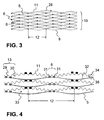
- a stack 10 with a plurality of structured sheet-metal foils 11 and smooth layers 5 (eg likewise sheet-metal foils or metallic nonwovens) is shown.
- the stack 10 is shown in a still non-wound state, that is to say essentially has a straight course direction 28.
- the connection points 6 of the metal foils are also shown to one another. As a result of the fact that the formation of such connection points 6 (soldered connections) are formed only in the mounted state, that is to say in the winding state, in the interior of the housing Fig.
- connection points in particular the position for an adhesive (eg adhesive) on which after the winding process, for example, powdered solder is positioned, which ultimately leads to the formation of the connecting points shown here by way of example and illustratively, with reference to the structured metal foil 11 (marked here dark) and bottom connection points (highlighted here).
- adhesive eg adhesive
- the similar, lower-side connection points in this case towards the lower smooth layer 5, comply with the specified distance 12 in the direction of progression 28 of, for example, at least 20 mm.
- the mutually adjacent connection points do not have a constant spacing 12 in the direction of progression 28 of the finished honeycomb body 1.
- Fig. 4 now shows a variant, wherein each connection point with two solder points 31 (or solder joints) on adjacent structure extrema 13, so either a survey 29 or a sink 30, is formed. Between the connection points 6, a plurality of extremes 13 of the structure of the structured sheet metal foil 11 are provided. It should only be noted at this point that usually the number of structural extras 13 between similar joints (shown in the same color) in the course direction is normally significantly higher than shown here by way of example, in particular at least 15 structural extras are in between.
- the smooth sheets 5 are made with a coating 32 to prevent unwanted compounds. Although this is preferably provided here on the top 34 and the bottom 35 of the smooth layer 5 (in particular sheet metal foil), in exceptional situations, a unilateral provision of an example oxide layer suffice. In any case, it should be ensured that a connection of the metallic layers, for example as a result of diffusion, is avoided and consequently relatively large cells 33 can form under stress.
- a large cell 33 is formed, for example, with a section of a smooth layer 5 and a section of a structured metal foil 11, the cell being delimited by two identical connection points (shown here for lower-side connection points) and further Cell boundary is formed by means of the structured sheet metal foil 11 with at least 15 structural extras 13.
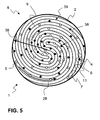
- Fig. 5 illustrates a cross section through a honeycomb body 1, for example, through the first section 14 from Fig. 2 , Here now again distributed over the cross section arranged connection points 6 are illustrated. Shown is the housing 2, in which here S-shaped wound several smooth metallic layers 5 and structured metal foils 11 are alternately arranged and wound so that the entire cross-section 8 is filled within the housing 2. The adjoining smooth layers 5 and structured or corrugated metal foils 11 form the channels 4.
- the connection points 6 are executed in the direction 28 of the layer 5 alternately towards the top or bottom. Therefore, the color markers (light, dark) of the connection points 6 alternate in the direction of progression 28.
- Fig. 5 also illustrates different zones along the radius 36, wherein a decreasing frequency of the number of connection points 6 per zone shown can be seen.
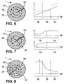
- Fig. 6 now shows schematically in the left part of a further cross section of a honeycomb body 1, where there is a first zone 38 can be seen around the axis of the honeycomb body 1. Concentric thereto, a second zone 39 and radially outside 36, a third zone 40 are provided. The right part now illustrates how the frequency of the connection points 6 behaves over the radius 36 or the three zones 38, 39, 40. In the diagram, two possible embodiments are illustrated. Thus, with respect to the first variant (solid line), a continuous increase in the density of the connection points 6 is realized. In the second variant (dotted line), in the first zone 38, the frequency is initially increased slightly, kept at a constant value in the second zone 39 and in the third zone 40 of a value changed compared to the second zone 39 (in this case significantly larger). increased again.
- Fig. 7 is similar in construction Fig. 6 ,
- the honeycomb body 1 has an outer, up to the housing hinan reaching third zone 40, which includes the first zone 39 and second zone 38.
- the first zone 38 and the second zone 39 are in this case designed in each case as a quarter-circle segments, which are arranged alternately to each other. These together form a circular central area.
- On the right of the diagram it can be seen that in the outer, third zone 40, a relatively constant density value of the connection points is provided.
- the first zone 38 and second zone 39 have a varying profile of the density of the connection points, so that, for example, the different winding or prestressing of the layers can be taken into account here.
- Fig. 8 again shows an embodiment in which the zones 38, 39 and 40 are not arranged concentrically about the axis 17 but about an offset center 37.
- the zones are not concentric, but deviate in one, Overlying or adjacent manner can be positioned to each other.
- the diagram shown on the right it can be stated that over the radius 36, an increase in the frequency, in particular up to the center 37 is observed and then there is a drop in the frequency here, the second zone 39 and finally the third Zone 40 extends.
- Fig. 9 illustrates a particularly preferred embodiment of a structured layer 5, or a structured sheet metal foil 11, for which the invention can find particular application.
- connection point 6 is illustrated for a survey 29. This consists of two adjacent to the apex of the elevation 29 placed soldering or soldering 31, which are here strip-shaped and formed parallel to the elevation 29.
- connection point 6 can be produced, in particular, by applying an adhesive in the region of the soldering points 31 (eg printed), then arranging the layers into the honeycomb structure, adding solder powder through the channels to the adhesive via the end face, and adhered solder material ultimately forms a connection point 6 after a thermal treatment of the honeycomb structure.
Landscapes
- Chemical & Material Sciences (AREA)
- Chemical Kinetics & Catalysis (AREA)
- Engineering & Computer Science (AREA)
- Health & Medical Sciences (AREA)
- Toxicology (AREA)
- Combustion & Propulsion (AREA)
- Mechanical Engineering (AREA)
- General Engineering & Computer Science (AREA)
- Exhaust Gas After Treatment (AREA)
- Catalysts (AREA)
- Laminated Bodies (AREA)
- Filtering Of Dispersed Particles In Gases (AREA)
Claims (11)
- Corps en nid d'abeilles (1) présentant au moins un boîtier (2) et une structure en nid d'abeilles (3) avec une pluralité de canaux (4), la structure en nid d'abeilles (3) étant formée avec au moins une couche métallique (5) au moins partiellement structurée, qui forme des points de liaison (6) fixant la structure en nid d'abeilles (3) et une section transversale (8) de la structure en nid d'abeilles (3) présentant des zones radiales (38, 39, 40) avec une densité de points de liaison (6) différente, au moins 1 % et au plus 20 % de points de contact internes (7) dans au moins une zone formant en outre un point de liaison (6) dans la section transversale (8).
- Corps en nid d'abeilles (1) selon la revendication 1, dans lequel la densité des points de liaison (6) dans la direction d'un rayon varie en continu de l'intérieur vers l'extérieur.
- Corps en nid d'abeilles (1) selon la revendication 1 ou 2, dans lequel la structure en nid d'abeilles (3) est formée avec au moins une pile (10) constituée d'une alternance de plusieurs feuilles de tôle structurées (11) et de couches métalliques lisses (5), les points de liaison (6) dans une feuille de tôle structurée (11) étant positionnés en alternance par rapport à des couches métalliques adjacentes (5).
- Corps en nid d'abeilles (1) selon l'une quelconque des revendications 1 à 3, dans lequel les points de liaison (6) sont réalisés le long d'une couche métallique (5) à des distances différentes (12) les uns des autres.
- Corps en nid d'abeilles (1) selon l'une quelconque des revendications 1 à 4, dans lequel les points de liaison (6) sont des points de brasage qui sont réalisés de manière à se raccorder à des extrêmes (13) de la couche métallique (5) au moins partiellement structurée.
- Corps en nid d'abeilles (1) selon l'une quelconque des revendications 1 à 5, dans lequel les points de liaison (6) ne sont réalisés que dans au moins une portion partielle (14) de l'étendue (16) de la structure en nid d'abeilles (3) dans la direction de son axe (17).
- Corps en nid d'abeilles (1) selon la revendication 6, dans lequel deux portions partielles (14, 15) espacées l'une de l'autre dans la direction de l'axe (17) sont prévues, les points de liaison (6) se recouvrant, vu dans la direction de l'axe (17).
- Corps en nid d'abeilles (1) selon l'une quelconque des revendications 1 à 7, dans lequel la structure en nid d'abeilles (3) est connectée au boîtier (2) au moyen de toutes les couches métalliques (5) et sur toute l'étendue (16) de la structure en nid d'abeilles (3).
- Corps en nid d'abeilles (1) selon l'une quelconque des revendications 1 à 8, dans lequel l'au moins une couche métallique (5) au moins partiellement structurée est réalisée avec au moins un évasement (18) ou une ouverture (19).
- Unité de purification de gaz d'échappement (20) présentant au moins un corps en nid d'abeilles (1) selon l'une quelconque des revendications 1 à 9.
- Véhicule automobile (21) présentant au moins une unité de purification de gaz d'échappement (20) selon la revendication 10.
Priority Applications (1)
| Application Number | Priority Date | Filing Date | Title |
|---|---|---|---|
| PL09715097T PL2250352T3 (pl) | 2008-02-27 | 2009-02-06 | Element o strukturze typu plastra miodu z elastycznymi strefami |
Applications Claiming Priority (2)
| Application Number | Priority Date | Filing Date | Title |
|---|---|---|---|
| DE102008011263A DE102008011263A1 (de) | 2008-02-27 | 2008-02-27 | Wabenkörper mit Flexibilitätszonen |
| PCT/EP2009/051403 WO2009106417A1 (fr) | 2008-02-27 | 2009-02-06 | Corps en nid d'abeilles comprenant des zones de flexibilité |
Publications (2)
| Publication Number | Publication Date |
|---|---|
| EP2250352A1 EP2250352A1 (fr) | 2010-11-17 |
| EP2250352B1 true EP2250352B1 (fr) | 2013-04-10 |
Family
ID=40651378
Family Applications (1)
| Application Number | Title | Priority Date | Filing Date |
|---|---|---|---|
| EP09715097.3A Active EP2250352B1 (fr) | 2008-02-27 | 2009-02-06 | Corps en nid d'abeilles comprenant des zones de flexibilité |
Country Status (12)
| Country | Link |
|---|---|
| US (1) | US10054024B2 (fr) |
| EP (1) | EP2250352B1 (fr) |
| JP (1) | JP5340317B2 (fr) |
| KR (1) | KR101369609B1 (fr) |
| CN (1) | CN101960110B (fr) |
| BR (1) | BRPI0908487B1 (fr) |
| DE (1) | DE102008011263A1 (fr) |
| MX (1) | MX2010009294A (fr) |
| MY (1) | MY153318A (fr) |
| PL (1) | PL2250352T3 (fr) |
| RU (1) | RU2493384C2 (fr) |
| WO (1) | WO2009106417A1 (fr) |
Families Citing this family (5)
| Publication number | Priority date | Publication date | Assignee | Title |
|---|---|---|---|---|
| DE102008022518A1 (de) * | 2008-05-07 | 2009-11-12 | Emitec Gesellschaft Für Emissionstechnologie Mbh | Wabenkörper mit radial verschieden ausgeführten Verbindungsstellen |
| US20160031027A1 (en) * | 2011-09-05 | 2016-02-04 | Basf Corporation | Method For Applying Brazing Material To Metal Honeycomb Matrix, Metal Honeycomb Matrix And Manufacturing Method Thereof |
| DE102017207151A1 (de) * | 2017-04-27 | 2018-10-31 | Continental Automotive Gmbh | Metallischer Wabenkörper mit haftungsverbessernden Mikrostrukturen |
| US11312662B2 (en) * | 2018-05-04 | 2022-04-26 | Corning Incorporated | High isostatic strength honeycomb structures and extrusion dies therefor |
| FR3108678B1 (fr) * | 2020-03-31 | 2022-04-22 | Faurecia Systemes Dechappement | Organe de chauffage pour un dispositif de purification de gaz d’échappement |
Family Cites Families (15)
| Publication number | Priority date | Publication date | Assignee | Title |
|---|---|---|---|---|
| DE3534904A1 (de) * | 1985-09-30 | 1987-04-02 | Interatom | Aus blechen gewickelter oder geschichteter metallischer katalysatortraegerkoerper mit doppel- oder mehrfachwellenstruktur |
| DE3818512A1 (de) * | 1988-05-31 | 1989-12-07 | Interatom | Verfahren zum beleimen und beloten eines metallischen katalysator-traegerkoerpers und zugehoerige vorrichtung |
| DE4111712A1 (de) * | 1991-04-10 | 1992-10-22 | Emitec Emissionstechnologie | Elektrisch leitfaehiger wabenkoerper |
| DE4132439A1 (de) * | 1991-09-28 | 1993-04-01 | Behr Gmbh & Co | Abgaskatalysator |
| ATE145964T1 (de) * | 1992-09-26 | 1996-12-15 | Showa Aircraft Ind | Wabenkörper zum reinigen von abgas, und verfahren zu seiner herstellung |
| JPH11197519A (ja) * | 1998-01-08 | 1999-07-27 | Honda Motor Co Ltd | 排気ガス浄化触媒用金属担体 |
| DE10200069A1 (de) * | 2002-01-03 | 2003-07-24 | Emitec Emissionstechnologie | Wabenstruktur und Verfahren zu deren Beleimung und Belotung |
| DE10257113A1 (de) * | 2002-12-05 | 2004-06-24 | Emitec Gesellschaft Für Emissionstechnologie Mbh | Partikelfalle mit beschichteter Faserlage |
| CN1460553A (zh) * | 2003-05-26 | 2003-12-10 | 蒋建东 | 用于柴油机催化氧化净化器的基体 |
| US20050054526A1 (en) * | 2003-09-08 | 2005-03-10 | Engelhard Corporation | Coated substrate and process of preparation thereof |
| CN1242159C (zh) * | 2003-09-23 | 2006-02-15 | 夏琦 | 金属蜂窝体的制造方法 |
| DE102004058285A1 (de) * | 2004-12-02 | 2006-06-08 | Emitec Gesellschaft Für Emissionstechnologie Mbh | Verbindungsmaterial zum Positionieren von Lotmaterial, Verfahren zur Herstellung eines Wabenkörpers und entsprechender Wabenkörper |
| DE102005028044A1 (de) * | 2005-06-17 | 2006-12-28 | Emitec Gesellschaft Für Emissionstechnologie Mbh | Herstellung von, insbesondere großen, Wabenkörpern für die mobile Abgasnachbehandlung |
| DE102005038572A1 (de) * | 2005-08-12 | 2007-02-15 | Emitec Gesellschaft Für Emissionstechnologie Mbh | Vorrichtung und Verfahren zur Herstellung metallischer Wabenkörper mit mindestens einem Formsegment |
| DE102008022518A1 (de) * | 2008-05-07 | 2009-11-12 | Emitec Gesellschaft Für Emissionstechnologie Mbh | Wabenkörper mit radial verschieden ausgeführten Verbindungsstellen |
-
2008
- 2008-02-27 DE DE102008011263A patent/DE102008011263A1/de not_active Withdrawn
-
2009
- 2009-02-06 RU RU2010139574/06A patent/RU2493384C2/ru active
- 2009-02-06 EP EP09715097.3A patent/EP2250352B1/fr active Active
- 2009-02-06 JP JP2010548060A patent/JP5340317B2/ja active Active
- 2009-02-06 WO PCT/EP2009/051403 patent/WO2009106417A1/fr active Application Filing
- 2009-02-06 BR BRPI0908487-8A patent/BRPI0908487B1/pt active IP Right Grant
- 2009-02-06 KR KR1020107021333A patent/KR101369609B1/ko active IP Right Grant
- 2009-02-06 CN CN200980106895.4A patent/CN101960110B/zh active Active
- 2009-02-06 MX MX2010009294A patent/MX2010009294A/es active IP Right Grant
- 2009-02-06 PL PL09715097T patent/PL2250352T3/pl unknown
- 2009-02-06 MY MYPI2010003788A patent/MY153318A/en unknown
-
2010
- 2010-08-27 US US12/869,860 patent/US10054024B2/en active Active
Also Published As
| Publication number | Publication date |
|---|---|
| PL2250352T3 (pl) | 2013-08-30 |
| JP2011513043A (ja) | 2011-04-28 |
| BRPI0908487A2 (pt) | 2015-08-18 |
| US20110033345A1 (en) | 2011-02-10 |
| WO2009106417A1 (fr) | 2009-09-03 |
| KR20100125357A (ko) | 2010-11-30 |
| MY153318A (en) | 2015-01-29 |
| JP5340317B2 (ja) | 2013-11-13 |
| US10054024B2 (en) | 2018-08-21 |
| RU2010139574A (ru) | 2012-04-27 |
| RU2493384C2 (ru) | 2013-09-20 |
| MX2010009294A (es) | 2011-03-04 |
| CN101960110B (zh) | 2014-12-24 |
| KR101369609B1 (ko) | 2014-03-04 |
| DE102008011263A1 (de) | 2009-09-03 |
| EP2250352A1 (fr) | 2010-11-17 |
| CN101960110A (zh) | 2011-01-26 |
| BRPI0908487B1 (pt) | 2021-05-25 |
Similar Documents
| Publication | Publication Date | Title |
|---|---|---|
| EP1743697B1 (fr) | Bande métallique avec microstructure | |
| EP1830042B1 (fr) | Mélangeur statique et dispositif de traitement de gaz d'échappement | |
| EP1706608B1 (fr) | Corps en nid d'abeilles compose de couches comprenant des parties inversees et de couches comprenant des contre-structures | |
| DE20117873U1 (de) | Offener Filterkörper mit verbesserten Strömungseigenschaften | |
| EP2283215B1 (fr) | Corps en nid d'abeilles avec des points de liaison distincts | |
| EP2250352B1 (fr) | Corps en nid d'abeilles comprenant des zones de flexibilité | |
| EP2250353B1 (fr) | Élément alvéolaire pourvu d'une zone sans liaison | |
| EP2250354B1 (fr) | Élément alvéolaire pourvu d'emplacements de liaison flexibles | |
| EP1902203B1 (fr) | Couche filtrante pour un element alveolaire, notamment conique, de traitement de gaz d'echappement et procede pour fabriquer cette couche filtrante | |
| EP2229510B1 (fr) | Corps alvéolé avec matériau métallique structuré | |
| EP1525378B1 (fr) | Couche metallique a parties presentant des epaisseurs de materiau differentes, son procede de production et corps en nid d'abeille produits au moins partiellement a partir desdites couches metalliques | |
| EP1922148B1 (fr) | Procede pour realiser un element alveolaire annulaire et element alveolaire annulaire | |
| EP1633506B1 (fr) | Procede et dispositif pour produire une bande de tole structuree | |
| EP2194251B1 (fr) | Fixation autoporteuse pour corps de support de catalyseur | |
| EP1787705A1 (fr) | Dispositif filtrant, en particulier, pour un système de traitement des gaz d'échappement d'un moteur à combustion interne du type Diesel | |
| EP1329602B2 (fr) | Bande métallique avec structure gaufrée pour l'usage à la purification de gaz d'échappement et outil et procédé de fabrication d'une telle bande | |
| DE102008033795A1 (de) | Wabenkörper, insbesondere Katalysatorkörper für Kraftfahrzeuge | |
| DE10235767C1 (de) | Blechlage mit Bereichen unterschiedlicher Materialdicke, Verfahren zur Herstellung einer solchen Blechlage und aus solchen Blechlagen hergestellter Wabenkörper | |
| DE10218856A1 (de) | Kalibrierter Katalysator-Trägerkörper mit Wellmantel und Verfahren zu dessen Herstellung | |
| DE10254763A1 (de) | Gekrümmtes Mantelrohr mit Strömungsbeeinflusser, Verfahren zur Herstellung und Verwendung | |
| WO2008128650A1 (fr) | Corps moulé céramique pour un filtre à particules diesel |
Legal Events
| Date | Code | Title | Description |
|---|---|---|---|
| PUAI | Public reference made under article 153(3) epc to a published international application that has entered the european phase |
Free format text: ORIGINAL CODE: 0009012 |
|
| 17P | Request for examination filed |
Effective date: 20100816 |
|
| AK | Designated contracting states |
Kind code of ref document: A1 Designated state(s): AT BE BG CH CY CZ DE DK EE ES FI FR GB GR HR HU IE IS IT LI LT LU LV MC MK MT NL NO PL PT RO SE SI SK TR |
|
| AX | Request for extension of the european patent |
Extension state: AL BA RS |
|
| DAX | Request for extension of the european patent (deleted) | ||
| RIC1 | Information provided on ipc code assigned before grant |
Ipc: F01N 3/28 20060101AFI20120913BHEP |
|
| GRAP | Despatch of communication of intention to grant a patent |
Free format text: ORIGINAL CODE: EPIDOSNIGR1 |
|
| GRAS | Grant fee paid |
Free format text: ORIGINAL CODE: EPIDOSNIGR3 |
|
| GRAA | (expected) grant |
Free format text: ORIGINAL CODE: 0009210 |
|
| AK | Designated contracting states |
Kind code of ref document: B1 Designated state(s): AT BE BG CH CY CZ DE DK EE ES FI FR GB GR HR HU IE IS IT LI LT LU LV MC MK MT NL NO PL PT RO SE SI SK TR |
|
| REG | Reference to a national code |
Ref country code: GB Ref legal event code: FG4D Free format text: NOT ENGLISH |
|
| REG | Reference to a national code |
Ref country code: CH Ref legal event code: EP Ref country code: AT Ref legal event code: REF Ref document number: 606144 Country of ref document: AT Kind code of ref document: T Effective date: 20130415 |
|
| REG | Reference to a national code |
Ref country code: IE Ref legal event code: FG4D Free format text: LANGUAGE OF EP DOCUMENT: GERMAN |
|
| REG | Reference to a national code |
Ref country code: DE Ref legal event code: R096 Ref document number: 502009006808 Country of ref document: DE Effective date: 20130606 |
|
| REG | Reference to a national code |
Ref country code: SE Ref legal event code: TRGR |
|
| PG25 | Lapsed in a contracting state [announced via postgrant information from national office to epo] |
Ref country code: SI Free format text: LAPSE BECAUSE OF FAILURE TO SUBMIT A TRANSLATION OF THE DESCRIPTION OR TO PAY THE FEE WITHIN THE PRESCRIBED TIME-LIMIT Effective date: 20130410 |
|
| REG | Reference to a national code |
Ref country code: PL Ref legal event code: T3 |
|
| REG | Reference to a national code |
Ref country code: NL Ref legal event code: VDEP Effective date: 20130410 Ref country code: LT Ref legal event code: MG4D |
|
| PG25 | Lapsed in a contracting state [announced via postgrant information from national office to epo] |
Ref country code: IS Free format text: LAPSE BECAUSE OF FAILURE TO SUBMIT A TRANSLATION OF THE DESCRIPTION OR TO PAY THE FEE WITHIN THE PRESCRIBED TIME-LIMIT Effective date: 20130810 Ref country code: ES Free format text: LAPSE BECAUSE OF FAILURE TO SUBMIT A TRANSLATION OF THE DESCRIPTION OR TO PAY THE FEE WITHIN THE PRESCRIBED TIME-LIMIT Effective date: 20130721 Ref country code: GR Free format text: LAPSE BECAUSE OF FAILURE TO SUBMIT A TRANSLATION OF THE DESCRIPTION OR TO PAY THE FEE WITHIN THE PRESCRIBED TIME-LIMIT Effective date: 20130711 Ref country code: FI Free format text: LAPSE BECAUSE OF FAILURE TO SUBMIT A TRANSLATION OF THE DESCRIPTION OR TO PAY THE FEE WITHIN THE PRESCRIBED TIME-LIMIT Effective date: 20130410 Ref country code: NL Free format text: LAPSE BECAUSE OF FAILURE TO SUBMIT A TRANSLATION OF THE DESCRIPTION OR TO PAY THE FEE WITHIN THE PRESCRIBED TIME-LIMIT Effective date: 20130410 Ref country code: LT Free format text: LAPSE BECAUSE OF FAILURE TO SUBMIT A TRANSLATION OF THE DESCRIPTION OR TO PAY THE FEE WITHIN THE PRESCRIBED TIME-LIMIT Effective date: 20130410 Ref country code: PT Free format text: LAPSE BECAUSE OF FAILURE TO SUBMIT A TRANSLATION OF THE DESCRIPTION OR TO PAY THE FEE WITHIN THE PRESCRIBED TIME-LIMIT Effective date: 20130812 Ref country code: NO Free format text: LAPSE BECAUSE OF FAILURE TO SUBMIT A TRANSLATION OF THE DESCRIPTION OR TO PAY THE FEE WITHIN THE PRESCRIBED TIME-LIMIT Effective date: 20130710 |
|
| PG25 | Lapsed in a contracting state [announced via postgrant information from national office to epo] |
Ref country code: HR Free format text: LAPSE BECAUSE OF FAILURE TO SUBMIT A TRANSLATION OF THE DESCRIPTION OR TO PAY THE FEE WITHIN THE PRESCRIBED TIME-LIMIT Effective date: 20130410 Ref country code: BG Free format text: LAPSE BECAUSE OF FAILURE TO SUBMIT A TRANSLATION OF THE DESCRIPTION OR TO PAY THE FEE WITHIN THE PRESCRIBED TIME-LIMIT Effective date: 20130710 Ref country code: CY Free format text: LAPSE BECAUSE OF FAILURE TO SUBMIT A TRANSLATION OF THE DESCRIPTION OR TO PAY THE FEE WITHIN THE PRESCRIBED TIME-LIMIT Effective date: 20130410 Ref country code: LV Free format text: LAPSE BECAUSE OF FAILURE TO SUBMIT A TRANSLATION OF THE DESCRIPTION OR TO PAY THE FEE WITHIN THE PRESCRIBED TIME-LIMIT Effective date: 20130410 |
|
| PG25 | Lapsed in a contracting state [announced via postgrant information from national office to epo] |
Ref country code: EE Free format text: LAPSE BECAUSE OF FAILURE TO SUBMIT A TRANSLATION OF THE DESCRIPTION OR TO PAY THE FEE WITHIN THE PRESCRIBED TIME-LIMIT Effective date: 20130410 Ref country code: DK Free format text: LAPSE BECAUSE OF FAILURE TO SUBMIT A TRANSLATION OF THE DESCRIPTION OR TO PAY THE FEE WITHIN THE PRESCRIBED TIME-LIMIT Effective date: 20130410 Ref country code: CZ Free format text: LAPSE BECAUSE OF FAILURE TO SUBMIT A TRANSLATION OF THE DESCRIPTION OR TO PAY THE FEE WITHIN THE PRESCRIBED TIME-LIMIT Effective date: 20130410 Ref country code: SK Free format text: LAPSE BECAUSE OF FAILURE TO SUBMIT A TRANSLATION OF THE DESCRIPTION OR TO PAY THE FEE WITHIN THE PRESCRIBED TIME-LIMIT Effective date: 20130410 |
|
| PLBE | No opposition filed within time limit |
Free format text: ORIGINAL CODE: 0009261 |
|
| STAA | Information on the status of an ep patent application or granted ep patent |
Free format text: STATUS: NO OPPOSITION FILED WITHIN TIME LIMIT |
|
| PG25 | Lapsed in a contracting state [announced via postgrant information from national office to epo] |
Ref country code: RO Free format text: LAPSE BECAUSE OF FAILURE TO SUBMIT A TRANSLATION OF THE DESCRIPTION OR TO PAY THE FEE WITHIN THE PRESCRIBED TIME-LIMIT Effective date: 20130410 |
|
| 26N | No opposition filed |
Effective date: 20140113 |
|
| REG | Reference to a national code |
Ref country code: DE Ref legal event code: R097 Ref document number: 502009006808 Country of ref document: DE Effective date: 20140113 |
|
| BERE | Be: lapsed |
Owner name: EMITEC G.- FUR EMISSIONSTECHNOLOGIE MBH Effective date: 20140228 |
|
| PG25 | Lapsed in a contracting state [announced via postgrant information from national office to epo] |
Ref country code: MC Free format text: LAPSE BECAUSE OF FAILURE TO SUBMIT A TRANSLATION OF THE DESCRIPTION OR TO PAY THE FEE WITHIN THE PRESCRIBED TIME-LIMIT Effective date: 20130410 Ref country code: LU Free format text: LAPSE BECAUSE OF FAILURE TO SUBMIT A TRANSLATION OF THE DESCRIPTION OR TO PAY THE FEE WITHIN THE PRESCRIBED TIME-LIMIT Effective date: 20140206 |
|
| REG | Reference to a national code |
Ref country code: CH Ref legal event code: PL |
|
| PG25 | Lapsed in a contracting state [announced via postgrant information from national office to epo] |
Ref country code: LI Free format text: LAPSE BECAUSE OF NON-PAYMENT OF DUE FEES Effective date: 20140228 Ref country code: CH Free format text: LAPSE BECAUSE OF NON-PAYMENT OF DUE FEES Effective date: 20140228 |
|
| REG | Reference to a national code |
Ref country code: IE Ref legal event code: MM4A |
|
| PG25 | Lapsed in a contracting state [announced via postgrant information from national office to epo] |
Ref country code: IE Free format text: LAPSE BECAUSE OF NON-PAYMENT OF DUE FEES Effective date: 20140206 Ref country code: BE Free format text: LAPSE BECAUSE OF NON-PAYMENT OF DUE FEES Effective date: 20140228 |
|
| REG | Reference to a national code |
Ref country code: AT Ref legal event code: MM01 Ref document number: 606144 Country of ref document: AT Kind code of ref document: T Effective date: 20140206 |
|
| PG25 | Lapsed in a contracting state [announced via postgrant information from national office to epo] |
Ref country code: AT Free format text: LAPSE BECAUSE OF NON-PAYMENT OF DUE FEES Effective date: 20140206 |
|
| REG | Reference to a national code |
Ref country code: FR Ref legal event code: PLFP Year of fee payment: 8 |
|
| PG25 | Lapsed in a contracting state [announced via postgrant information from national office to epo] |
Ref country code: MT Free format text: LAPSE BECAUSE OF FAILURE TO SUBMIT A TRANSLATION OF THE DESCRIPTION OR TO PAY THE FEE WITHIN THE PRESCRIBED TIME-LIMIT Effective date: 20130410 |
|
| REG | Reference to a national code |
Ref country code: DE Ref legal event code: R081 Ref document number: 502009006808 Country of ref document: DE Owner name: VITESCO TECHNOLOGIES GMBH, DE Free format text: FORMER OWNER: EMITEC GESELLSCHAFT FUER EMISSIONSTECHNOLOGIE MBH, 53797 LOHMAR, DE Ref country code: DE Ref legal event code: R082 Ref document number: 502009006808 Country of ref document: DE Ref country code: DE Ref legal event code: R081 Ref document number: 502009006808 Country of ref document: DE Owner name: CONTINENTAL AUTOMOTIVE GMBH, DE Free format text: FORMER OWNER: EMITEC GESELLSCHAFT FUER EMISSIONSTECHNOLOGIE MBH, 53797 LOHMAR, DE |
|
| REG | Reference to a national code |
Ref country code: GB Ref legal event code: 732E Free format text: REGISTERED BETWEEN 20160331 AND 20160406 |
|
| PG25 | Lapsed in a contracting state [announced via postgrant information from national office to epo] |
Ref country code: TR Free format text: LAPSE BECAUSE OF FAILURE TO SUBMIT A TRANSLATION OF THE DESCRIPTION OR TO PAY THE FEE WITHIN THE PRESCRIBED TIME-LIMIT Effective date: 20130410 Ref country code: HU Free format text: LAPSE BECAUSE OF FAILURE TO SUBMIT A TRANSLATION OF THE DESCRIPTION OR TO PAY THE FEE WITHIN THE PRESCRIBED TIME-LIMIT; INVALID AB INITIO Effective date: 20090206 |
|
| REG | Reference to a national code |
Ref country code: FR Ref legal event code: PLFP Year of fee payment: 9 |
|
| REG | Reference to a national code |
Ref country code: FR Ref legal event code: PLFP Year of fee payment: 10 |
|
| PGFP | Annual fee paid to national office [announced via postgrant information from national office to epo] |
Ref country code: GB Payment date: 20180216 Year of fee payment: 10 |
|
| PG25 | Lapsed in a contracting state [announced via postgrant information from national office to epo] |
Ref country code: MK Free format text: LAPSE BECAUSE OF FAILURE TO SUBMIT A TRANSLATION OF THE DESCRIPTION OR TO PAY THE FEE WITHIN THE PRESCRIBED TIME-LIMIT Effective date: 20130410 |
|
| GBPC | Gb: european patent ceased through non-payment of renewal fee |
Effective date: 20190206 |
|
| PG25 | Lapsed in a contracting state [announced via postgrant information from national office to epo] |
Ref country code: GB Free format text: LAPSE BECAUSE OF NON-PAYMENT OF DUE FEES Effective date: 20190206 |
|
| REG | Reference to a national code |
Ref country code: DE Ref legal event code: R081 Ref document number: 502009006808 Country of ref document: DE Owner name: VITESCO TECHNOLOGIES GMBH, DE Free format text: FORMER OWNER: CONTINENTAL AUTOMOTIVE GMBH, 30165 HANNOVER, DE |
|
| REG | Reference to a national code |
Ref country code: DE Ref legal event code: R081 Ref document number: 502009006808 Country of ref document: DE Owner name: VITESCO TECHNOLOGIES GMBH, DE Free format text: FORMER OWNER: VITESCO TECHNOLOGIES GMBH, 30165 HANNOVER, DE |
|
| REG | Reference to a national code |
Ref country code: DE Ref legal event code: R084 Ref document number: 502009006808 Country of ref document: DE |
|
| P01 | Opt-out of the competence of the unified patent court (upc) registered |
Effective date: 20230830 |
|
| PGFP | Annual fee paid to national office [announced via postgrant information from national office to epo] |
Ref country code: DE Payment date: 20240229 Year of fee payment: 16 |
|
| PGFP | Annual fee paid to national office [announced via postgrant information from national office to epo] |
Ref country code: SE Payment date: 20240219 Year of fee payment: 16 Ref country code: PL Payment date: 20240125 Year of fee payment: 16 Ref country code: IT Payment date: 20240228 Year of fee payment: 16 Ref country code: FR Payment date: 20240221 Year of fee payment: 16 |