EP2249987B1 - Werkzeug zur spanentfernenden bearbeitung - Google Patents
Werkzeug zur spanentfernenden bearbeitung Download PDFInfo
- Publication number
- EP2249987B1 EP2249987B1 EP09708464.4A EP09708464A EP2249987B1 EP 2249987 B1 EP2249987 B1 EP 2249987B1 EP 09708464 A EP09708464 A EP 09708464A EP 2249987 B1 EP2249987 B1 EP 2249987B1
- Authority
- EP
- European Patent Office
- Prior art keywords
- coupling section
- ridges
- tool according
- grooves
- cassette
- Prior art date
- Legal status (The legal status is an assumption and is not a legal conclusion. Google has not performed a legal analysis and makes no representation as to the accuracy of the status listed.)
- Active
Links
Images



Classifications
-
- B—PERFORMING OPERATIONS; TRANSPORTING
- B23—MACHINE TOOLS; METAL-WORKING NOT OTHERWISE PROVIDED FOR
- B23C—MILLING
- B23C5/00—Milling-cutters
- B23C5/16—Milling-cutters characterised by physical features other than shape
- B23C5/20—Milling-cutters characterised by physical features other than shape with removable cutter bits or teeth or cutting inserts
- B23C5/22—Securing arrangements for bits or teeth or cutting inserts
- B23C5/2298—Securing arrangements for bits or teeth or cutting inserts secured by resilient/flexible means
- B23C5/2306—Securing arrangements for bits or teeth or cutting inserts secured by resilient/flexible means for plate-like cutting inserts fitted on an intermediate carrier, e.g. shank fixed in the cutter body
-
- B—PERFORMING OPERATIONS; TRANSPORTING
- B23—MACHINE TOOLS; METAL-WORKING NOT OTHERWISE PROVIDED FOR
- B23C—MILLING
- B23C5/00—Milling-cutters
- B23C5/02—Milling-cutters characterised by the shape of the cutter
- B23C5/08—Disc-type cutters
-
- B—PERFORMING OPERATIONS; TRANSPORTING
- B23—MACHINE TOOLS; METAL-WORKING NOT OTHERWISE PROVIDED FOR
- B23C—MILLING
- B23C5/00—Milling-cutters
- B23C5/16—Milling-cutters characterised by physical features other than shape
- B23C5/20—Milling-cutters characterised by physical features other than shape with removable cutter bits or teeth or cutting inserts
- B23C5/22—Securing arrangements for bits or teeth or cutting inserts
- B23C5/2204—Securing arrangements for bits or teeth or cutting inserts with cutting inserts clamped against the walls of the recess in the cutter body by a clamping member acting upon the wall of a hole in the insert
- B23C5/2208—Securing arrangements for bits or teeth or cutting inserts with cutting inserts clamped against the walls of the recess in the cutter body by a clamping member acting upon the wall of a hole in the insert for plate-like cutting inserts
- B23C5/2213—Securing arrangements for bits or teeth or cutting inserts with cutting inserts clamped against the walls of the recess in the cutter body by a clamping member acting upon the wall of a hole in the insert for plate-like cutting inserts having a special shape
-
- B—PERFORMING OPERATIONS; TRANSPORTING
- B23—MACHINE TOOLS; METAL-WORKING NOT OTHERWISE PROVIDED FOR
- B23C—MILLING
- B23C5/00—Milling-cutters
- B23C5/16—Milling-cutters characterised by physical features other than shape
- B23C5/20—Milling-cutters characterised by physical features other than shape with removable cutter bits or teeth or cutting inserts
- B23C5/22—Securing arrangements for bits or teeth or cutting inserts
- B23C5/2204—Securing arrangements for bits or teeth or cutting inserts with cutting inserts clamped against the walls of the recess in the cutter body by a clamping member acting upon the wall of a hole in the insert
- B23C5/2226—Securing arrangements for bits or teeth or cutting inserts with cutting inserts clamped against the walls of the recess in the cutter body by a clamping member acting upon the wall of a hole in the insert for plate-like cutting inserts fitted on an intermediate carrier, e.g. shank fixed in the cutter body
-
- B—PERFORMING OPERATIONS; TRANSPORTING
- B23—MACHINE TOOLS; METAL-WORKING NOT OTHERWISE PROVIDED FOR
- B23C—MILLING
- B23C2200/00—Details of milling cutting inserts
- B23C2200/08—Rake or top surfaces
- B23C2200/085—Rake or top surfaces discontinuous
-
- B—PERFORMING OPERATIONS; TRANSPORTING
- B23—MACHINE TOOLS; METAL-WORKING NOT OTHERWISE PROVIDED FOR
- B23C—MILLING
- B23C2200/00—Details of milling cutting inserts
- B23C2200/16—Supporting or bottom surfaces
- B23C2200/165—Supporting or bottom surfaces with one or more grooves
-
- B—PERFORMING OPERATIONS; TRANSPORTING
- B23—MACHINE TOOLS; METAL-WORKING NOT OTHERWISE PROVIDED FOR
- B23C—MILLING
- B23C2260/00—Details of constructional elements
- B23C2260/80—Serrations
-
- Y—GENERAL TAGGING OF NEW TECHNOLOGICAL DEVELOPMENTS; GENERAL TAGGING OF CROSS-SECTIONAL TECHNOLOGIES SPANNING OVER SEVERAL SECTIONS OF THE IPC; TECHNICAL SUBJECTS COVERED BY FORMER USPC CROSS-REFERENCE ART COLLECTIONS [XRACs] AND DIGESTS
- Y10—TECHNICAL SUBJECTS COVERED BY FORMER USPC
- Y10T—TECHNICAL SUBJECTS COVERED BY FORMER US CLASSIFICATION
- Y10T407/00—Cutters, for shaping
- Y10T407/19—Rotary cutting tool
- Y10T407/1906—Rotary cutting tool including holder [i.e., head] having seat for inserted tool
- Y10T407/1932—Rotary cutting tool including holder [i.e., head] having seat for inserted tool with means to fasten tool seat to holder
-
- Y—GENERAL TAGGING OF NEW TECHNOLOGICAL DEVELOPMENTS; GENERAL TAGGING OF CROSS-SECTIONAL TECHNOLOGIES SPANNING OVER SEVERAL SECTIONS OF THE IPC; TECHNICAL SUBJECTS COVERED BY FORMER USPC CROSS-REFERENCE ART COLLECTIONS [XRACs] AND DIGESTS
- Y10—TECHNICAL SUBJECTS COVERED BY FORMER USPC
- Y10T—TECHNICAL SUBJECTS COVERED BY FORMER US CLASSIFICATION
- Y10T407/00—Cutters, for shaping
- Y10T407/22—Cutters, for shaping including holder having seat for inserted tool
- Y10T407/2202—Plural spaced seats and common holder
-
- Y—GENERAL TAGGING OF NEW TECHNOLOGICAL DEVELOPMENTS; GENERAL TAGGING OF CROSS-SECTIONAL TECHNOLOGIES SPANNING OVER SEVERAL SECTIONS OF THE IPC; TECHNICAL SUBJECTS COVERED BY FORMER USPC CROSS-REFERENCE ART COLLECTIONS [XRACs] AND DIGESTS
- Y10—TECHNICAL SUBJECTS COVERED BY FORMER USPC
- Y10T—TECHNICAL SUBJECTS COVERED BY FORMER US CLASSIFICATION
- Y10T407/00—Cutters, for shaping
- Y10T407/23—Cutters, for shaping including tool having plural alternatively usable cutting edges
- Y10T407/235—Cutters, for shaping including tool having plural alternatively usable cutting edges with integral chip breaker, guide or deflector
-
- Y—GENERAL TAGGING OF NEW TECHNOLOGICAL DEVELOPMENTS; GENERAL TAGGING OF CROSS-SECTIONAL TECHNOLOGIES SPANNING OVER SEVERAL SECTIONS OF THE IPC; TECHNICAL SUBJECTS COVERED BY FORMER USPC CROSS-REFERENCE ART COLLECTIONS [XRACs] AND DIGESTS
- Y10—TECHNICAL SUBJECTS COVERED BY FORMER USPC
- Y10T—TECHNICAL SUBJECTS COVERED BY FORMER US CLASSIFICATION
- Y10T408/00—Cutting by use of rotating axially moving tool
- Y10T408/44—Cutting by use of rotating axially moving tool with means to apply transient, fluent medium to work or product
- Y10T408/45—Cutting by use of rotating axially moving tool with means to apply transient, fluent medium to work or product including Tool with duct
-
- Y—GENERAL TAGGING OF NEW TECHNOLOGICAL DEVELOPMENTS; GENERAL TAGGING OF CROSS-SECTIONAL TECHNOLOGIES SPANNING OVER SEVERAL SECTIONS OF THE IPC; TECHNICAL SUBJECTS COVERED BY FORMER USPC CROSS-REFERENCE ART COLLECTIONS [XRACs] AND DIGESTS
- Y10—TECHNICAL SUBJECTS COVERED BY FORMER USPC
- Y10T—TECHNICAL SUBJECTS COVERED BY FORMER US CLASSIFICATION
- Y10T408/00—Cutting by use of rotating axially moving tool
- Y10T408/89—Tool or Tool with support
- Y10T408/909—Having peripherally spaced cutting edges
- Y10T408/9095—Having peripherally spaced cutting edges with axially extending relief channel
- Y10T408/9097—Spiral channel
Definitions
- This invention relates to a cutting tool or tool for chip removing machining of the type that comprises, on one hand, a basic body, in which at least one seating is included, which is delimited by a base surface and a support protruding in relation to the same, the base surface including a first coupling section in the form of one or more ridges and grooves, and, on the other hand, a replaceable cutting insert having an upperside, an underside and a clearance surface extending between the same and transforming into the upperside via at least one cutting edge, the underside including a second coupling section having or one more grooves and ridges, the last-mentioned ones of which engage the grooves of the first coupling section, and vice versa, at the same time as a part of the clearance surface is pressed against the support.
- Tools of the kind in question are primarily intended for machining workpieces of metal.
- a slitting cutter which in the traditional way includes a circular disc, the periphery of which is equipped with a plurality of replaceable cutting inserts of a hard and wear-resistant material, e.g., cemented carbide.
- These cutting inserts are mounted in separate cassettes of steel or the like, which are semi-permanently connected with the disc and placed in peripherally spaced-apart chip pockets, and can be exchanged individually if damage would occur, i.e., without the disc in its entirety needing to be discarded.
- a wedge tightenable by means of a screw is used, by means of which a so-called serration surface (in the form of straight and parallel ridges and grooves) of the underside of the cassette can be forcefully pressed into a co-operating serration surface of the individual chip pocket of the disc.
- the cross-sectionally wedge-shaped ridges of one of the serration surfaces is pressed into the grooves of the other serration surface, and vice versa, while providing a highly stable joint between the cassette and the disc, at the same time as the lateral position of the cassette, and thereby of the cutting insert, can be fine-adjusted in a simple way before the cassette is finally fixed by means of the wedge.
- the cutting insert is in turn mountable in a so-called insert seat or seating in the upperside of the cassette.
- said seating is delimited by a plane bottom surface or base surface, as well as two plane support surfaces, orientated perpendicularly to each other, viz.
- the cutting insert was formed with a set of ridges, which extend parallel to two side clearance surfaces between front and rear ends, at least the front one of which includes the cutting edge requisite for the chip removal, while the base surface of the seating was formed with ridges, which extend in the plane of the disc (i.e., perpendicularly to the centre axis of the disc), viz. from a front or outer end of the base surface toward the rear support surface.
- the particular side support surface could be spared and the manufacture of the tool be facilitated.
- the present invention sets out from the commercially available side and face milling cutter, which has been developed based on the above-mentioned patent document, and which is defined in the preamble of claim 1.
- the interface between the cutting insert and the cassette formed with two co-operating serration surfaces or coupling sections in the known side and face milling cutter works in a meritorious way as long as the cutting inserts are reasonably great, but if the cutting inserts have to be made with limited dimensions, problems occur so far that the ridges and the grooves of the coupling section of the cassette cannot be given sufficiently a great length to efficiently counteract rotation of the cutting insert and guarantee a stable fixation of the same.
- the coupling section of the cassette is in practice manufactured by milling using a shank-end mill, by means of which a desired number of grooves are milled out in the initially plane base surface of the seating of the cassette.
- the base surface of the seating is small in relation to the milling cutter, only short grooves and ridges can be provided. Supposing that the smallest shank-end mill, which can be used, has a diameter, which is as great as the length of the base surface, the length of the grooves and of the ridges is maximized to at most half of said diameter, because otherwise, the milling cutter would need to be fed forward so far that the same damages the protruding support surface.
- a primary object of the invention is to provide a tool in which the seating or seatings, which has or have the purpose of receiving replaceable cutting inserts, can be formed with base surfaces, the coupling sections of which have an optimum projection area and the ridges a considerable length.
- a shank-end mill can be brought past the support surface without coming into contact with the same, making it possible to form the greater part of the base surface with long, force-absorbing ridges.
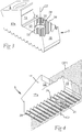
- a side and face milling cutter has been selected shown in Figs. 1 and 2 , which is composed of, on one hand, a basic body 1 in the form of a circular disc or blade, which is rotatable around a centre axis C1, and, on the other hand, a large number of replaceable cutting inserts 2, which are mounted along the circumference of the disc. More precisely, the individual cutting insert 2 is mounted in a so-called cassette 3, which constitutes a part of the basic body by being semi-permanently connected thereto.
- Each such cassette 3 is placed adjacent to a chip pocket 4, opening in the periphery of the disc 1, and fixed by means of a wedge body 5, which, by means of a tightening screw 6, can be drawn in between, on one hand, a plane wedge surface 7 of the disc, and, on the other hand, a plane wedge surface 8 of the upperside of the cassette 3.
- an interface is used in the form of a so-called serration surface 9 of the disc body 1 and a co-operating serration surface 10 (see also Figs. 4 and 6 ) of the underside of the cassette 3.
- the serration surfaces 9, 10 are in this case plane and include a plurality of straight and mutually parallel ridges, which are spaced-apart by grooves, the ridges of one of the serration surfaces engaging the grooves of the other one, and vice versa.
- the ridges are cross-sectionally wedge-shaped and formed so that they do not bottom in the appurtenant grooves. Furthermore, each individual ridge runs parallel to the centre axis C1 of the disc body, and therefore forms 90° angle with the plane of the disc. This means that the position of the cassette laterally in relation to the disc can be fine-adjusted in a simple way without the radial distance of the cutting insert from the centre axis C1 being altered. Thus, the cassette can be displaced in relation to the serration surface 9 with the wedge body 5 loosely tightened, whereupon the last-mentioned one is finally tightened in order to fix the cassette immovably.
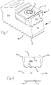
- a seating (a so-called insert seat), in its entirety designated 11, is formed, which is delimited by a bottom surface or base surface 12, as well as a rear support protruding in relation to the same, which in this case is in the form of a plane surface 13 included in a lug 14, in which also the wedge surface 8 is included.
- the underside of the cassette is entirely occupied by the serration surface 10, the ridges and grooves of which are designated 15 and 16, respectively.
- the cassette is delimited by two plane and mutually parallel side surfaces 17a, 17b, which extend between front and rear end surfaces 18, 19.
- CP1 designates a vertical central plane, which is situated halfway between the side surfaces 17a, 17b.
- a hole 20 mouths having a female thread in which the male thread of a tightening screw 21 (see Fig. 7 ) can be tightened.
- the hole 20 is through and therefore also mouths in the underside of the cassette.
- the cutting insert includes an upperside 22, an underside 23 and a circumferential clearance surface generally designated 24, which in this case, when the cutting insert has a quadrangular basic shape, includes four part surfaces, viz. a front end surface 24a, a rear end surface 24b as well as two side surfaces 24c. Of these surfaces, the two side surfaces 24c are similar and situated at equally large distances from a common central plane CP2.
- the cutting insert 2 includes only one cutting edge. This is designated 25 and formed between the upperside 22 of the cutting insert and the front part surface 24a, which is included in the clearance surface 24.
- the cutting edge 25 is in this case straight along the major part of its length, but transforms into arched part edges 25a at both ends thereof. From the cutting edge 25, the clearance surface 24 clears from or diverges in the downward direction as well as in the backward direction in the traditional way.
- a series of ridges and grooves 26, 27 are formed for co-operation with a series of ridges and grooves in the base surface 12 of the cassette 3.
- the surface, which is occupied by the ridges/grooves 26, 27 and the corresponding arrangement in the base surface 12 is henceforth denominated "coupling section".
- the ridges and grooves included in the coupling section of the cassette are designated 28, 29 (see Figs. 3 and 5 ).
- the cutting insert 2 includes a through, vertical hole 30, the centre axis of which is designated C3. The upper mouth of the hole is delimited by a conical surface 31.
- Figs. 7 and 8 the cutting insert 2 is shown mounted in the cassette 3, more precisely by means of the tightening screw 21.
- the ridges 26 of the underside of the cutting insert are in engagement with the grooves 29 of the cassette and the ridges 28 in engagement with the grooves 27.
- the ridges of the coupling section of the cassette extend parallel to the side surfaces of the cassette (and thereby perpendicularly to the rear support surface), at the same time as the ridges of the underside of the cutting insert run perpendicularly to the cutting edge or essentially parallel to the side surfaces of the cutting insert. Therefore, when the cutting insert - and thereby also the seating of the cassette - is small, difficulties arise to give the ridges of the coupling section of the cassette a sufficient length in order to guarantee a stable fixation of the cutting insert.
- the shank-end mill which is usually used for milling the grooves of the coupling section of the cassette, cannot be brought closer to the rear support surface than the distance that corresponds to half the diameter of the shank-end mill.
- the above-mentioned problems are solved by the fact that the ridges (and the grooves) of the two coupling sections of the cassette and the cutting insert, respectively, are angled or inclined in relation to the central planes CP1 and CP2 thereof.
- 32 designates the coupling section, which is formed by the ridges 28 and the grooves 29, i.e., the part of the base surface 12 of the seating 11, which can be coupled together mechanically with the ridges 26 and the grooves 27 of the underside of the cutting insert.
- the ridges 28 of the coupling section 32 form an acute angle ⁇ with the central plane CP1.
- the ridges 28 form an acute angle ⁇ . Because the support surface 13, in this case, extends perpendicularly to the central plane CP1, the angle ⁇ forms a complementary angle to the angle ⁇ .
- imaginary extensions of the ridges will extend by the side of the support surface.
- the ridges can be provided by means of a shank-end mill, which can freely pass beside the support surface 13, i.e., without damaging the same, the projection surface of the coupling section 32 and the length of the ridges becoming greater than if the ridges were parallel to the centre plane and thereby would need to end at a comparatively great distance from the support surface 13.
- the borderlines which determine the contour shape of the base surface 12, will become straight.
- the ridges 28 extend up to said borderlines, i.e., the opposite ends of the ridges are located along said borderlines.
- a first end of each ridge is designated 28a, while the opposite end is designated 28b.
- all first ends 28a are located along one of the side surfaces 17b, while certain opposite, second ends 28b are located along the front end surface 18 of the cassette, while the other second ends 28b are situated along the opposite end surface 17a of the cassette.
- a free surface 33 which, in this case, has a triangular shape and tapers toward the end of an adjacent ridge, which is situated closest to the support surface.
- the length L of the base surface is determined by the distance between the countersink 34 and the front end surface 18 of the cassette.
- the width of the cassette is designated W.
- the angle ⁇ as well as the angle ⁇ amount to 45°, the coupling section 32 formed by the ridges and the grooves occupying approx. 74 % of the total area of the base surface 12.
- the lug 14 has been formed with a chamfer surface 35, which, like the ridges, extends at 45° angle to the central plane CP1.
- the width of the support surface 13 in relation to the total width W of the cassette is reduced, but it is still sufficiently great to reliably carry the radial forces, which act on the cutting insert.
- the width of the support surface 13 amounts to approx. 75 % of the width of the cassette W. Of course, this width may vary upward as well as downward. At all events, it should however amount to at least 50 %.
- the angle ⁇ as well as the angle ⁇ may vary, even independently of each other, namely if the support surface 13 is located at another angle than at 90° to the central plane CP1.
- the area of the coupling section 32 (on condition that the shape and size of the base surface 12 is the same and that the support surface 13 has one and the same width) decreases by a decreasing angle ⁇ , and vice versa.
- the angle ⁇ should however not be less than 25°.
- ⁇ should not be greater than 50°, because otherwise the ability of the ridges is reduced to carry lateral forces from the cutting insert to too great an extent.
- the area of the coupling section 32 should amount to at least 2/3 of the total area of the base surface 12.
- the free surface 33 is, on one hand, situated on a level under the highest level of the coupling section 32, such as this is represented by the crests of the ridges 28, and, on the other hand, on a level above the lowest level of the coupling section, such as this is represented by the bottoms of the grooves 29.
- the bottom of the countersink 34 is situated on a level under the free surface 33.
- the cutting insert (see again Figs. 9-12 ) is symmetrical in relation to the central plane CP2, and has only one chip removing cutting edge 25.
- the ridges 26 of the second coupling section which is formed on the underside 23 of the cutting insert, extend at an acute angle ⁇ to the central plane CP2.
- ⁇ and a should be equally large, i.e., 45° in the example. Because the cutting edge 25 extends perpendicularly to the central plane CP2, ⁇ forms a complementary angle to ⁇ . If ⁇ is 45° also ⁇ will accordingly be 45°.
- the coupling section of the underside of the cutting insert extends along the entire underside by the fact that all grooves 27 open in the different part surfaces of the clearance surface 24. Also the ridges 26 should extend at least 25° and at most 50° angle to said central plane.
- Fig. 5 it is seen that the hole 20 for the tightening screw 21 is displaced somewhat sidewards in relation to the central plane CP1.
- the corresponding hole 30 of the cutting insert is, however, centrically situated, so far that the centre axis C3 thereof coincides with the central plane CP2 of the cutting insert.
- the screw 21, which has a conical head (not visible), consists of steel having a certain inherent elasticity. Thanks to the eccentricity between the holes 20 and 30, the screw 21 will, when it is tightened, apply not only a downwardly directed force, but also a spring force to the cutting insert, which displaces the same diagonally towards the right and rearward in Fig. 5 , until the rear end surface 24b of the cutting insert is pressed in close contact against the rear support surface 13.
- a fundamental advantage of the invention is that the L-shaped (as viewed from the side) seating, which has the purpose of stably anchoring replaceable cutting inserts, in particular small cutting inserts, can by means of conventional, simple milling (or equivalent machining) be given a proportionally great surface at the same time as the longest ridge or ridges thereof extend up to the immediate vicinity of the protruding support. In such a way, it is guaranteed that parts of the ridges also engage the rear part of the corresponding coupling section of the cutting insert so that rotation of the cutting insert is efficiently counteracted.
- the front end of the coupling section of the base surface, where the greatest forces from the cutting insert are carried is still formed with ridges along the entire width of the base surface, at the same time as the longest ridge or ridges extend all the way up to the rear end of the base surface.
- the cutting insert has a symmetrical basic shape and includes only one, front cutting edge.
- indexable cutting inserts having two or more cutting edges, provided that the acute angle at which the ridges of the coupling sections are inclined amounts to exactly 45°.
- the described inclination of the ridges can be utilized in a particularly advantageous way, if dominant cutting forces are applied to the cutting insert in the direction diagonally toward an individual corner of the cutting insert.
- the ridges By locating the ridges at a suitable angle to the dominant line of force action, e.g., 90° or near 90°, the ridges can be utilized in order to carry, together with the rear support, great cutting forces, in addition to efficiently counteracting rotation of the cutting insert.
- the rear support does not necessarily have to be a plane surface, such as in the example. It is merely important that a rear support sticks up in relation to the base surface of the seating and has at least line or point contact with the rear end surface of the cutting insert in order to prevent displacement of the cutting insert in the backward direction.
- a protruding upright e.g., a stud, having a smaller width
- the geometrical design of the ridges and the grooves included in the coupling sections may be modified in various ways. Even if the ridges generally are cross-sectionally wedge-shaped, the flank angles (which normally amount to 60°) may be varied within fairly wide limits. If the cutting insert is merely subjected to moderate lateral forces, which aim to rotate the same, it is also feasible to form the individual coupling sections with only one or a few ridges and grooves instead of as many as five according to the example. Furthermore, the cutting insert may have a round, instead of the polygonal, basic shape.
- the invention is also applicable to other cutting tools than milling cutters, e.g., tools for turning as well as drilling.
- Particular advantages are foreseen in an application to exactly turning tools, because the turning inserts for these are often exposed to cutting forces, which act diagonally toward a corner of the insert.
- the seating or insert seat which has the purpose of receiving the replaceable cutting insert, of course does not need to be formed in a cassette or another part, e.g., a shim plate, which is semi-permanently connected with the rest of the basic body.
- the seating may also be formed directly in a solid basic body.
Landscapes
- Engineering & Computer Science (AREA)
- Mechanical Engineering (AREA)
- Cutting Tools, Boring Holders, And Turrets (AREA)
- Milling Processes (AREA)
- Drilling Tools (AREA)
Claims (16)
- Werkzeug zur spanabhebenden Bearbeitung welcheszum einen einen Grundkörper (1) aufweist, welcher mindestens einen Sitz (11) aufweist, der durch eine Grundfläche (12) und eine relativ dazu hervorstehenden Stützfläche (13) begrenzt ist, wobei die Grundfläche (12) einen ersten Verbindungsabschnitt (32) in Form einer oder mehrerer Rippen (28) und Nuten (29) umfasst undzum anderen eine austauschbare Schneidkante (2) aufweist ,mit einer Oberseite (22), einer Unterseite (23) und einer sich dazwischen erstreckenden Freifläche (24), die über mindestens eine Schneidkante (25) in die Oberseite (22) übergeht,wobei die Unterseite (23) einen zweiten Verbindungsabschnitt mit einer oder mehreren Nuten (27) und Rippen (26) umfasst,wobei Letztere in die Nuten des ersten Verbindungsabschnitts (32) eingreifen und umgekehrt,wobei gleichzeitig ein Teil (24b) der Freifläche (24) gegen die Stützfläche (13) gedrückt wird,dadurch gekennzeichnet, dasseine gedachte Verlängerung der jeweiligen Rippe (28) des ersten Verbindungsabschnitts (32) sich von der Seite der Stützfläche (13) erstreckt, und dass die Stützfläche durch eine Oberfläche (13) gebildet wird, welche unter einem spitzen Winkel (β) zu der jeweiligen Rippe (28) des ersten Verbindungsabschnitts (32) verläuft.
- Werkzeug nach Anspruch 1, dadurch gekennzeichnet, dass der erste Verbindungsabschnitt (32) eine Mehrzahl von durch Nuten (29) voneinander beabstandeten Rippen (28) aufweist, deren gegenüberliegende Enden (28a, 28b) entlang einer Grenzlinie verlaufen, welche die Kontur der Grundfläche (12) bestimmt.
- Werkzeug nach einem der vorhergehenden Ansprüche, dadurch gekennzeichnet, dass die Grundfläche (12), zusätzlich zu dem Verbindungsabschnitt (32), eine Freifläche (33) aufweist, welche sich zu den Enden einer benachbarten Rippe (28), die der Stützfläche (13) am nächsten liegt, hin verjüngt, wobei sich gleichzeitig der Verbindungsabschnitt hin zu der Stützfläche verjüngt.
- Werkzeug nach Anspruch 3, dadurch gekennzeichnet, dass die Freifläche (33) einerseits auf einem Niveau unterhalb des höchsten Niveaus des ersten Verbindungsabschnitts (32) liegt, welches durch den Grat einer oder mehrerer Rippen (28) definiert wird und anderseits auf einem Niveau über dem niedrigsten Niveau des Verbindungsabschnitts liegt, welches durch den Grund einer oder mehrerer Nuten (29) definiert wird.
- Werkzeug nach einem der vorhergehenden Ansprüche, dadurch gekennzeichnet, dass die Breite der Stützfläche (13) mindestens die Hälfte der Breite (W) der Grundfläche (12) beträgt, welche durch den Abstand zwischen zwei zueinander beabstandeten seitlichen Grenzlinien (17a, 17b) definiert wird.
- Werkzeug nach einem der vorhergehenden Ansprüche, dadurch gekennzeichnet, dass ein schachtförmiges Einsenkung (34) zwischen der Grundfläche (12) und der Stützfläche (13) gebildet wird.
- Werkzeug nach einem der vorhergehenden Ansprüche, dadurch gekennzeichnet, dass der erste Verbindungsabschnitt (32) eine Vorsprungsfläche aufweist, welcher mindestens 2/3 der gesamten Vorsprungsfläche der Grundfläche (12) einnimmt.
- Werkzeug nach einem der vorhergehenden Ansprüche, dadurch gekennzeichnet, dass der spitze Winkel (β) zwischen der Stützfläche (13) und der Rippe (28) mindestens 25° beträgt.
- Werkzeug nach einem der vorhergehenden Ansprüche, dadurch gekennzeichnet, dass der spitze Winkel (β) zwischen der Stützfläche (13) und der Rippe (28) höchstens 50° beträgt.
- Werkzeug nach einem der vorhergehenden Ansprüche, dadurch gekennzeichnet, dass der spitze Winkel (β) zwischen der Stützfläche (13) und der Rippe (28) 45° beträgt.
- Werkzeug nach einem der vorhergehenden Ansprüche, dadurch gekennzeichnet, dass der jeweilige Sitz (11) des Grundkörpers (1) durch ein separates Element (3) gebildet wird, welches in dem Grundkörper durch eine semi-permanente Verbindung aufgenommen ist.
- Werkzeug nach Anspruch 11 in Form eines Scheiben- und Planfräsers, dessen Grundkörper eine um eine zentrale Achse (C1) drehbare kreisförmige Scheibe (1) ist, deren Umfangsrand mit einer Mehrzahl von Schneideinsätzen (2) ausgestattet ist, die jeweils in einem Element in Form einer Kassette (3) befestigt sind, welche semi-permanent an einer Schnittstelle mit der Scheibe verbunden ist, wobei die Schnittstelle eine erste Verzahnungsfläche (9) in Form einer Serie von in der Scheibe gebildeten Rippen und Nuten, sowie eine zweite Verzahnungsfläche (10) aufweist, die an einer Unterseite der Kassette in Form von Nuten und Rippen ausgebildet ist, welche parallel zu der zentralen Achse (C1) der Scheibe verlaufen und wobei letztere in die Nuten der ersten Verzahnungsfläche eingreifen und umgekehrt, wobei der erste Verbindungsabschnitt (32) in der Oberseite der Kassette (3) gebildet wird, genauer gesagt zwischen einem hinteren Ansatz (14) und einer vorderen Stirnfläche (18), neben welcher die Kassette durch ein Paar von wechselseitig voneinander beabstandeten Seitenflächen (17a, 17b) begrenzt ist, welche sich von der vorderen Stirnfläche (18) zu einer hinteren Stirnfläche (19) erstrecken, dadurch gekennzeichnet, dass die jeweilige Rippe (28) des ersten Verbindungsabschnitts (32) unter einem spitzen Winkel (α) zu der jeweiligen Seitenfläche (17b) verläuft um eine gedachte Verlängerung derselben auf die Seite des Ansatzes (14) zu richten.
- Werkzeug nach Anspruch 12, dadurch gekennzeichnet, dass von Paaren gegenüberliegender, erster und zweiter Enden (28a, 28b) der Rippen (28) des ersten Verbindungsabschnittes (32) alle ersten Enden (28a) entlang einer Seitenfläche (17b) verlaufen, während zumindest einige gegenüberliegende, zweite Enden (28b) auf der gesamten Breite der vorderen Stirnfläche (18) der Kassette liegen.
- Werkzeug nach einem der Ansprüche 12 oder 13, dadurch gekennzeichnet, dass der Winkel (α) zwischen der Seitenfläche (17b) und der Rippe (28) mindestens 25° beträgt.
- Werkzeug nach einem der Ansprüche 12 bis 14, dadurch gekennzeichnet, dass der Winkel (α) zwischen der Seitenfläche (17b) und der Rippe (28) höchstens 50° beträgt.
- Werkzeug nach einem der Ansprüche 12 bis 15, dadurch gekennzeichnet, dass der Winkel (α) zwischen der Seitenfläche (17b) und der Rippe (28) 45° beträgt.
Applications Claiming Priority (2)
| Application Number | Priority Date | Filing Date | Title |
|---|---|---|---|
| SE0800265A SE532002C2 (sv) | 2008-02-05 | 2008-02-05 | Verktyg för spånavskiljande bearbetning, samt grundkropp och skär härför |
| PCT/SE2009/050105 WO2009099386A1 (en) | 2008-02-05 | 2009-02-02 | Tool for chip removing machining, as well as a basic body and a cutting insert therefor |
Publications (3)
| Publication Number | Publication Date |
|---|---|
| EP2249987A1 EP2249987A1 (de) | 2010-11-17 |
| EP2249987A4 EP2249987A4 (de) | 2012-08-15 |
| EP2249987B1 true EP2249987B1 (de) | 2019-08-21 |
Family
ID=40931842
Family Applications (1)
| Application Number | Title | Priority Date | Filing Date |
|---|---|---|---|
| EP09708464.4A Active EP2249987B1 (de) | 2008-02-05 | 2009-02-02 | Werkzeug zur spanentfernenden bearbeitung |
Country Status (7)
| Country | Link |
|---|---|
| US (1) | US8475087B2 (de) |
| EP (1) | EP2249987B1 (de) |
| JP (1) | JP5666916B2 (de) |
| KR (1) | KR101558013B1 (de) |
| CN (1) | CN101925429A (de) |
| SE (1) | SE532002C2 (de) |
| WO (1) | WO2009099386A1 (de) |
Families Citing this family (24)
| Publication number | Priority date | Publication date | Assignee | Title |
|---|---|---|---|---|
| CA2727589A1 (en) * | 2008-06-13 | 2009-12-17 | Taegutec Ltd. | Cutting tool and cartridge for the same |
| SE535170C2 (sv) * | 2010-06-22 | 2012-05-08 | Sandvik Intellectual Property | Underläggsplatta till verktyg för skärande bearbetning samt verktyg |
| US8974154B2 (en) * | 2011-03-11 | 2015-03-10 | Sandvik Intellectual Property Ab | Cutting insert and shim for milling cutters |
| IL214781A0 (en) | 2011-08-22 | 2011-10-31 | Iscar Ltd | Cutting tool and cutting insert therefor |
| DE102011111513A1 (de) * | 2011-08-31 | 2013-02-28 | Simtek Ag | Zerspanungswerkzeug |
| ES2561096T3 (es) * | 2011-11-04 | 2016-02-24 | Walter Ag | Cartucho con medios de ajuste grueso y medios de ajuste fino |
| EP2596887B1 (de) * | 2011-11-23 | 2019-01-23 | Sandvik Intellectual Property AB | Schneidwerkzeug mit austauschbarem Einsatzsitzelement |
| US8678716B2 (en) * | 2012-04-19 | 2014-03-25 | Iscar, Ltd. | Cutting tool assembly with removable tool head |
| CN104768688B (zh) * | 2012-11-09 | 2017-04-26 | 格里森工场 | 具有条形刀片的径向可调整性的齿轮刀具 |
| WO2014093411A1 (en) * | 2012-12-14 | 2014-06-19 | The Gleason Works | Gear cutter with radial adjustability of square or rectangular stick blades |
| CN103894664B (zh) * | 2012-12-28 | 2016-07-06 | 株洲钻石切削刀具股份有限公司 | 一种定位准确的旋转切削刀具 |
| US9266174B2 (en) * | 2013-06-10 | 2016-02-23 | sp3 Cutting Tools, Inc. | Cutting tool |
| DE102014216731A1 (de) * | 2013-08-27 | 2015-03-05 | Schaeffler Technologies Gmbh & Co. Kg | Durch Presspassung verzahnter äußerer Laufring in einem Stator |
| CN104057112A (zh) * | 2014-06-26 | 2014-09-24 | 黑龙江八一农垦大学 | 装配式圆体成形车刀 |
| EP2965847B1 (de) * | 2014-07-09 | 2019-09-11 | Sandvik Intellectual Property AB | Schneideinsatz und Wälzschälwerkzeug |
| CN104368869A (zh) * | 2014-11-27 | 2015-02-25 | 株洲钻石切削刀具股份有限公司 | 一种拉削刀具 |
| WO2016203843A1 (ja) * | 2015-06-19 | 2016-12-22 | 株式会社タンガロイ | 工具ボデーおよび切削工具 |
| KR101677716B1 (ko) * | 2016-01-12 | 2016-11-18 | 한국야금 주식회사 | 절삭 인서트 및 이를 장착한 절삭 공구 |
| CN107295907A (zh) * | 2017-06-07 | 2017-10-27 | 江苏鼎钰生态农业科技有限公司 | 一种电动修枝机中的刀片 |
| EP3812066A1 (de) * | 2019-10-23 | 2021-04-28 | AB Sandvik Coromant | Werkzeughalter und ein trenn- und nutwerkzeug für einen indexierbaren revolver und bearbeitungsverfahren dafür |
| EP3815840B1 (de) | 2019-10-31 | 2023-10-04 | Sandvik Machining Solutions AB | Verfahren zur herstellung eines werkzeugteils |
| CN111546129B (zh) * | 2020-04-27 | 2021-07-16 | 南京信息职业技术学院 | 一种可以精确调定的浮动镗刀块 |
| WO2022027236A1 (zh) * | 2020-08-04 | 2022-02-10 | 株洲华锐精密工具股份有限公司 | 高速铣削刀具 |
| JP7678292B2 (ja) * | 2021-06-29 | 2025-05-16 | 株式会社Moldino | 切削工具、切削インサート |
Citations (1)
| Publication number | Priority date | Publication date | Assignee | Title |
|---|---|---|---|---|
| US2240360A (en) * | 1939-02-27 | 1941-04-29 | Barber Colman Co | Rotary cutter |
Family Cites Families (13)
| Publication number | Priority date | Publication date | Assignee | Title |
|---|---|---|---|---|
| GB818262A (en) * | 1955-02-23 | 1959-08-12 | Wesson Tool Company | Improvements in or relating to cutting tool holders |
| SE509363C2 (sv) * | 1995-09-25 | 1999-01-18 | Sandvik Ab | Fastspänningsanordning fjör skärplattor samt skärplatta avsedd för dylik anordning |
| SE9503867D0 (sv) | 1995-11-02 | 1995-11-02 | Sandvik Ab | Fräsverktyg |
| WO1999019104A1 (en) * | 1997-10-15 | 1999-04-22 | Sandvik Ab | Milling tool |
| SE514591C2 (sv) * | 1997-10-15 | 2001-03-19 | Sandvik Ab | Fräsverktyg |
| SE512977C2 (sv) * | 1998-10-27 | 2000-06-12 | Sandvik Ab | Fräsverktyg |
| SE515635C2 (sv) * | 2000-01-27 | 2001-09-17 | Sandvik Ab | Skivfräs jämte skär härför |
| US6702526B2 (en) * | 2002-04-29 | 2004-03-09 | Kennametal Inc. | Cutting tool |
| SE525878C2 (sv) * | 2002-10-10 | 2005-05-17 | Seco Tools Ab | Fräsverktyg och indexerbart skär med parallella sidor |
| IL157032A (en) * | 2003-07-21 | 2007-10-31 | Moshe Elbaz | Cutting head for rotary cutting tool |
| SE526770C2 (sv) | 2003-10-14 | 2005-11-01 | Sandvik Intellectual Property | Förfarande vid tillverkning av indexerbara skär samt indexerbart skär och skärverktyg med dylikt skär |
| SE526772C2 (sv) * | 2003-12-23 | 2005-11-01 | Sandvik Intellectual Property | Skärverktyg med serrationskopplingsytor samt förfarande för framställning av dessa |
| SE527850C2 (sv) * | 2004-02-24 | 2006-06-20 | Sandvik Intellectual Property | Skärverktyg samt grundkropp med kopplingsytor försedda med åsar |
-
2008
- 2008-02-05 SE SE0800265A patent/SE532002C2/sv not_active IP Right Cessation
-
2009
- 2009-02-02 JP JP2010545828A patent/JP5666916B2/ja not_active Expired - Fee Related
- 2009-02-02 KR KR1020107017329A patent/KR101558013B1/ko not_active Expired - Fee Related
- 2009-02-02 EP EP09708464.4A patent/EP2249987B1/de active Active
- 2009-02-02 WO PCT/SE2009/050105 patent/WO2009099386A1/en not_active Ceased
- 2009-02-02 CN CN200980102787XA patent/CN101925429A/zh active Pending
- 2009-02-04 US US12/365,245 patent/US8475087B2/en not_active Expired - Fee Related
Patent Citations (1)
| Publication number | Priority date | Publication date | Assignee | Title |
|---|---|---|---|---|
| US2240360A (en) * | 1939-02-27 | 1941-04-29 | Barber Colman Co | Rotary cutter |
Also Published As
| Publication number | Publication date |
|---|---|
| JP5666916B2 (ja) | 2015-02-12 |
| SE0800265L (sv) | 2009-08-06 |
| US20090196701A1 (en) | 2009-08-06 |
| EP2249987A1 (de) | 2010-11-17 |
| KR101558013B1 (ko) | 2015-10-06 |
| JP2011510829A (ja) | 2011-04-07 |
| CN101925429A (zh) | 2010-12-22 |
| KR20100111286A (ko) | 2010-10-14 |
| US8475087B2 (en) | 2013-07-02 |
| SE532002C2 (sv) | 2009-09-22 |
| WO2009099386A1 (en) | 2009-08-13 |
| EP2249987A4 (de) | 2012-08-15 |
Similar Documents
| Publication | Publication Date | Title |
|---|---|---|
| US8475087B2 (en) | Tool for chip removing machining, as well as a basic body and a cutting insert therefor | |
| EP2101947B1 (de) | Schneideinsatz und schneidwerkzeug | |
| EP1935539B1 (de) | Drehwerkzeug und Dreheinsatz | |
| CN100488679C (zh) | 切削刀片、切削刀具、垫板及安装切削刀片的方法 | |
| US8926234B2 (en) | Indexable end-milling insert | |
| US9144849B2 (en) | Cutting tool holding a plurality of types of cutting inserts | |
| US6508612B1 (en) | Milling cutter capable of using inserts of various geometrical shapes | |
| US8388270B2 (en) | Slotting cutter with cantilevered member | |
| EP1800779A2 (de) | Ein Werkzeug zur spananhebenden Bearbeitung sowie ein Grundkörper und ein Verriegelungsteil dafür | |
| SE530808C2 (sv) | Verktyg för spånavskiljande bearbetning, samt skär och grundkropp härför | |
| EP2759363B1 (de) | Werkzeug zur spanabhebenden Bearbeitung | |
| EP2616205B1 (de) | Schneideinsatz mit rückseitiger protuberanz | |
| US6488450B2 (en) | T-slot milling cutter and insert therefor | |
| EP1984140B1 (de) | Zahnradfräswerkzeug mit austauschbaren schneideinsätzen | |
| US7585137B2 (en) | Cutting tool and insert with serrated contact surfaces between holder and insert | |
| US10906107B2 (en) | Single-sided four-way indexable positive cutting insert and insert mill therefor |
Legal Events
| Date | Code | Title | Description |
|---|---|---|---|
| PUAI | Public reference made under article 153(3) epc to a published international application that has entered the european phase |
Free format text: ORIGINAL CODE: 0009012 |
|
| 17P | Request for examination filed |
Effective date: 20100906 |
|
| AK | Designated contracting states |
Kind code of ref document: A1 Designated state(s): AT BE BG CH CY CZ DE DK EE ES FI FR GB GR HR HU IE IS IT LI LT LU LV MC MK MT NL NO PL PT RO SE SI SK TR |
|
| AX | Request for extension of the european patent |
Extension state: AL BA RS |
|
| DAX | Request for extension of the european patent (deleted) | ||
| A4 | Supplementary search report drawn up and despatched |
Effective date: 20120716 |
|
| RIC1 | Information provided on ipc code assigned before grant |
Ipc: B23C 5/22 20060101AFI20120710BHEP |
|
| 17Q | First examination report despatched |
Effective date: 20120830 |
|
| STAA | Information on the status of an ep patent application or granted ep patent |
Free format text: STATUS: EXAMINATION IS IN PROGRESS |
|
| REG | Reference to a national code |
Ref country code: DE Ref legal event code: R079 Ref document number: 602009059533 Country of ref document: DE Free format text: PREVIOUS MAIN CLASS: B23C0005220000 Ipc: B23C0005080000 |
|
| GRAP | Despatch of communication of intention to grant a patent |
Free format text: ORIGINAL CODE: EPIDOSNIGR1 |
|
| STAA | Information on the status of an ep patent application or granted ep patent |
Free format text: STATUS: GRANT OF PATENT IS INTENDED |
|
| RIC1 | Information provided on ipc code assigned before grant |
Ipc: B23C 5/22 20060101ALI20190502BHEP Ipc: B23C 5/08 20060101AFI20190502BHEP |
|
| INTG | Intention to grant announced |
Effective date: 20190521 |
|
| GRAS | Grant fee paid |
Free format text: ORIGINAL CODE: EPIDOSNIGR3 |
|
| GRAA | (expected) grant |
Free format text: ORIGINAL CODE: 0009210 |
|
| STAA | Information on the status of an ep patent application or granted ep patent |
Free format text: STATUS: THE PATENT HAS BEEN GRANTED |
|
| AK | Designated contracting states |
Kind code of ref document: B1 Designated state(s): AT BE BG CH CY CZ DE DK EE ES FI FR GB GR HR HU IE IS IT LI LT LU LV MC MK MT NL NO PL PT RO SE SI SK TR |
|
| REG | Reference to a national code |
Ref country code: GB Ref legal event code: FG4D |
|
| REG | Reference to a national code |
Ref country code: CH Ref legal event code: EP |
|
| REG | Reference to a national code |
Ref country code: DE Ref legal event code: R096 Ref document number: 602009059533 Country of ref document: DE |
|
| REG | Reference to a national code |
Ref country code: AT Ref legal event code: REF Ref document number: 1169137 Country of ref document: AT Kind code of ref document: T Effective date: 20190915 |
|
| REG | Reference to a national code |
Ref country code: IE Ref legal event code: FG4D |
|
| REG | Reference to a national code |
Ref country code: LT Ref legal event code: MG4D |
|
| REG | Reference to a national code |
Ref country code: NL Ref legal event code: MP Effective date: 20190821 |
|
| PG25 | Lapsed in a contracting state [announced via postgrant information from national office to epo] |
Ref country code: NO Free format text: LAPSE BECAUSE OF FAILURE TO SUBMIT A TRANSLATION OF THE DESCRIPTION OR TO PAY THE FEE WITHIN THE PRESCRIBED TIME-LIMIT Effective date: 20191121 Ref country code: BG Free format text: LAPSE BECAUSE OF FAILURE TO SUBMIT A TRANSLATION OF THE DESCRIPTION OR TO PAY THE FEE WITHIN THE PRESCRIBED TIME-LIMIT Effective date: 20191121 Ref country code: SE Free format text: LAPSE BECAUSE OF FAILURE TO SUBMIT A TRANSLATION OF THE DESCRIPTION OR TO PAY THE FEE WITHIN THE PRESCRIBED TIME-LIMIT Effective date: 20190821 Ref country code: NL Free format text: LAPSE BECAUSE OF FAILURE TO SUBMIT A TRANSLATION OF THE DESCRIPTION OR TO PAY THE FEE WITHIN THE PRESCRIBED TIME-LIMIT Effective date: 20190821 Ref country code: LT Free format text: LAPSE BECAUSE OF FAILURE TO SUBMIT A TRANSLATION OF THE DESCRIPTION OR TO PAY THE FEE WITHIN THE PRESCRIBED TIME-LIMIT Effective date: 20190821 Ref country code: PT Free format text: LAPSE BECAUSE OF FAILURE TO SUBMIT A TRANSLATION OF THE DESCRIPTION OR TO PAY THE FEE WITHIN THE PRESCRIBED TIME-LIMIT Effective date: 20191223 Ref country code: HR Free format text: LAPSE BECAUSE OF FAILURE TO SUBMIT A TRANSLATION OF THE DESCRIPTION OR TO PAY THE FEE WITHIN THE PRESCRIBED TIME-LIMIT Effective date: 20190821 Ref country code: FI Free format text: LAPSE BECAUSE OF FAILURE TO SUBMIT A TRANSLATION OF THE DESCRIPTION OR TO PAY THE FEE WITHIN THE PRESCRIBED TIME-LIMIT Effective date: 20190821 |
|
| PG25 | Lapsed in a contracting state [announced via postgrant information from national office to epo] |
Ref country code: ES Free format text: LAPSE BECAUSE OF FAILURE TO SUBMIT A TRANSLATION OF THE DESCRIPTION OR TO PAY THE FEE WITHIN THE PRESCRIBED TIME-LIMIT Effective date: 20190821 Ref country code: LV Free format text: LAPSE BECAUSE OF FAILURE TO SUBMIT A TRANSLATION OF THE DESCRIPTION OR TO PAY THE FEE WITHIN THE PRESCRIBED TIME-LIMIT Effective date: 20190821 Ref country code: IS Free format text: LAPSE BECAUSE OF FAILURE TO SUBMIT A TRANSLATION OF THE DESCRIPTION OR TO PAY THE FEE WITHIN THE PRESCRIBED TIME-LIMIT Effective date: 20191221 Ref country code: GR Free format text: LAPSE BECAUSE OF FAILURE TO SUBMIT A TRANSLATION OF THE DESCRIPTION OR TO PAY THE FEE WITHIN THE PRESCRIBED TIME-LIMIT Effective date: 20191122 |
|
| REG | Reference to a national code |
Ref country code: AT Ref legal event code: MK05 Ref document number: 1169137 Country of ref document: AT Kind code of ref document: T Effective date: 20190821 |
|
| PG25 | Lapsed in a contracting state [announced via postgrant information from national office to epo] |
Ref country code: TR Free format text: LAPSE BECAUSE OF FAILURE TO SUBMIT A TRANSLATION OF THE DESCRIPTION OR TO PAY THE FEE WITHIN THE PRESCRIBED TIME-LIMIT Effective date: 20190821 |
|
| PG25 | Lapsed in a contracting state [announced via postgrant information from national office to epo] |
Ref country code: AT Free format text: LAPSE BECAUSE OF FAILURE TO SUBMIT A TRANSLATION OF THE DESCRIPTION OR TO PAY THE FEE WITHIN THE PRESCRIBED TIME-LIMIT Effective date: 20190821 Ref country code: RO Free format text: LAPSE BECAUSE OF FAILURE TO SUBMIT A TRANSLATION OF THE DESCRIPTION OR TO PAY THE FEE WITHIN THE PRESCRIBED TIME-LIMIT Effective date: 20190821 Ref country code: EE Free format text: LAPSE BECAUSE OF FAILURE TO SUBMIT A TRANSLATION OF THE DESCRIPTION OR TO PAY THE FEE WITHIN THE PRESCRIBED TIME-LIMIT Effective date: 20190821 Ref country code: PL Free format text: LAPSE BECAUSE OF FAILURE TO SUBMIT A TRANSLATION OF THE DESCRIPTION OR TO PAY THE FEE WITHIN THE PRESCRIBED TIME-LIMIT Effective date: 20190821 Ref country code: IT Free format text: LAPSE BECAUSE OF FAILURE TO SUBMIT A TRANSLATION OF THE DESCRIPTION OR TO PAY THE FEE WITHIN THE PRESCRIBED TIME-LIMIT Effective date: 20190821 Ref country code: DK Free format text: LAPSE BECAUSE OF FAILURE TO SUBMIT A TRANSLATION OF THE DESCRIPTION OR TO PAY THE FEE WITHIN THE PRESCRIBED TIME-LIMIT Effective date: 20190821 |
|
| PG25 | Lapsed in a contracting state [announced via postgrant information from national office to epo] |
Ref country code: IS Free format text: LAPSE BECAUSE OF FAILURE TO SUBMIT A TRANSLATION OF THE DESCRIPTION OR TO PAY THE FEE WITHIN THE PRESCRIBED TIME-LIMIT Effective date: 20200224 Ref country code: SK Free format text: LAPSE BECAUSE OF FAILURE TO SUBMIT A TRANSLATION OF THE DESCRIPTION OR TO PAY THE FEE WITHIN THE PRESCRIBED TIME-LIMIT Effective date: 20190821 Ref country code: CZ Free format text: LAPSE BECAUSE OF FAILURE TO SUBMIT A TRANSLATION OF THE DESCRIPTION OR TO PAY THE FEE WITHIN THE PRESCRIBED TIME-LIMIT Effective date: 20190821 |
|
| REG | Reference to a national code |
Ref country code: DE Ref legal event code: R097 Ref document number: 602009059533 Country of ref document: DE |
|
| PLBE | No opposition filed within time limit |
Free format text: ORIGINAL CODE: 0009261 |
|
| STAA | Information on the status of an ep patent application or granted ep patent |
Free format text: STATUS: NO OPPOSITION FILED WITHIN TIME LIMIT |
|
| PG2D | Information on lapse in contracting state deleted |
Ref country code: IS |
|
| 26N | No opposition filed |
Effective date: 20200603 |
|
| PG25 | Lapsed in a contracting state [announced via postgrant information from national office to epo] |
Ref country code: SI Free format text: LAPSE BECAUSE OF FAILURE TO SUBMIT A TRANSLATION OF THE DESCRIPTION OR TO PAY THE FEE WITHIN THE PRESCRIBED TIME-LIMIT Effective date: 20190821 |
|
| REG | Reference to a national code |
Ref country code: DE Ref legal event code: R119 Ref document number: 602009059533 Country of ref document: DE |
|
| REG | Reference to a national code |
Ref country code: CH Ref legal event code: PL |
|
| GBPC | Gb: european patent ceased through non-payment of renewal fee |
Effective date: 20200202 |
|
| REG | Reference to a national code |
Ref country code: BE Ref legal event code: MM Effective date: 20200229 |
|
| PG25 | Lapsed in a contracting state [announced via postgrant information from national office to epo] |
Ref country code: LU Free format text: LAPSE BECAUSE OF NON-PAYMENT OF DUE FEES Effective date: 20200202 Ref country code: MC Free format text: LAPSE BECAUSE OF FAILURE TO SUBMIT A TRANSLATION OF THE DESCRIPTION OR TO PAY THE FEE WITHIN THE PRESCRIBED TIME-LIMIT Effective date: 20190821 |
|
| PG25 | Lapsed in a contracting state [announced via postgrant information from national office to epo] |
Ref country code: CH Free format text: LAPSE BECAUSE OF NON-PAYMENT OF DUE FEES Effective date: 20200229 Ref country code: LI Free format text: LAPSE BECAUSE OF NON-PAYMENT OF DUE FEES Effective date: 20200229 |
|
| PG25 | Lapsed in a contracting state [announced via postgrant information from national office to epo] |
Ref country code: IE Free format text: LAPSE BECAUSE OF NON-PAYMENT OF DUE FEES Effective date: 20200202 Ref country code: GB Free format text: LAPSE BECAUSE OF NON-PAYMENT OF DUE FEES Effective date: 20200202 Ref country code: FR Free format text: LAPSE BECAUSE OF NON-PAYMENT OF DUE FEES Effective date: 20200229 Ref country code: DE Free format text: LAPSE BECAUSE OF NON-PAYMENT OF DUE FEES Effective date: 20200901 |
|
| PG25 | Lapsed in a contracting state [announced via postgrant information from national office to epo] |
Ref country code: BE Free format text: LAPSE BECAUSE OF NON-PAYMENT OF DUE FEES Effective date: 20200229 |
|
| PG25 | Lapsed in a contracting state [announced via postgrant information from national office to epo] |
Ref country code: MT Free format text: LAPSE BECAUSE OF FAILURE TO SUBMIT A TRANSLATION OF THE DESCRIPTION OR TO PAY THE FEE WITHIN THE PRESCRIBED TIME-LIMIT Effective date: 20190821 Ref country code: CY Free format text: LAPSE BECAUSE OF FAILURE TO SUBMIT A TRANSLATION OF THE DESCRIPTION OR TO PAY THE FEE WITHIN THE PRESCRIBED TIME-LIMIT Effective date: 20190821 |
|
| PG25 | Lapsed in a contracting state [announced via postgrant information from national office to epo] |
Ref country code: MK Free format text: LAPSE BECAUSE OF FAILURE TO SUBMIT A TRANSLATION OF THE DESCRIPTION OR TO PAY THE FEE WITHIN THE PRESCRIBED TIME-LIMIT Effective date: 20190821 |