EP2249560A1 - Reduzierung der DLP-Edge-Blending-Artefakte - Google Patents
Reduzierung der DLP-Edge-Blending-Artefakte Download PDFInfo
- Publication number
- EP2249560A1 EP2249560A1 EP10161178A EP10161178A EP2249560A1 EP 2249560 A1 EP2249560 A1 EP 2249560A1 EP 10161178 A EP10161178 A EP 10161178A EP 10161178 A EP10161178 A EP 10161178A EP 2249560 A1 EP2249560 A1 EP 2249560A1
- Authority
- EP
- European Patent Office
- Prior art keywords
- blend
- variance
- pixel
- pixel group
- intensity
- Prior art date
- Legal status (The legal status is an assumption and is not a legal conclusion. Google has not performed a legal analysis and makes no representation as to the accuracy of the status listed.)
- Granted
Links
Images
Classifications
-
- G—PHYSICS
- G09—EDUCATION; CRYPTOGRAPHY; DISPLAY; ADVERTISING; SEALS
- G09G—ARRANGEMENTS OR CIRCUITS FOR CONTROL OF INDICATING DEVICES USING STATIC MEANS TO PRESENT VARIABLE INFORMATION
- G09G5/00—Control arrangements or circuits for visual indicators common to cathode-ray tube indicators and other visual indicators
- G09G5/36—Control arrangements or circuits for visual indicators common to cathode-ray tube indicators and other visual indicators characterised by the display of a graphic pattern, e.g. using an all-points-addressable [APA] memory
- G09G5/37—Details of the operation on graphic patterns
- G09G5/377—Details of the operation on graphic patterns for mixing or overlaying two or more graphic patterns
-
- H—ELECTRICITY
- H04—ELECTRIC COMMUNICATION TECHNIQUE
- H04N—PICTORIAL COMMUNICATION, e.g. TELEVISION
- H04N5/00—Details of television systems
- H04N5/74—Projection arrangements for image reproduction, e.g. using eidophor
-
- H—ELECTRICITY
- H04—ELECTRIC COMMUNICATION TECHNIQUE
- H04N—PICTORIAL COMMUNICATION, e.g. TELEVISION
- H04N9/00—Details of colour television systems
- H04N9/12—Picture reproducers
- H04N9/31—Projection devices for colour picture display, e.g. using electronic spatial light modulators [ESLM]
- H04N9/3141—Constructional details thereof
- H04N9/3147—Multi-projection systems
-
- H—ELECTRICITY
- H04—ELECTRIC COMMUNICATION TECHNIQUE
- H04N—PICTORIAL COMMUNICATION, e.g. TELEVISION
- H04N9/00—Details of colour television systems
- H04N9/12—Picture reproducers
- H04N9/31—Projection devices for colour picture display, e.g. using electronic spatial light modulators [ESLM]
- H04N9/3179—Video signal processing therefor
- H04N9/3182—Colour adjustment, e.g. white balance, shading or gamut
Definitions
- the present invention pertains to the field of DLP projectors, and in particular, to a method of visual artefact reduction in the blend zone of two or more overlapping DLP projectors.
- DLP projectors use one or more digital micromirror devices (DMD) to reflect light and produce a picture.
- DMD digital micromirror devices
- Each DMD may contain more than 2 million pixel mirrors, and using pulse-width modulation (PWM), each pixel mirror is capable of producing various levels of light intensity, or shades between white and black.
- PWM pulse-width modulation
- each pixel mirror is rapidly repositioned (generally termed 'on' for white, and 'off' for black) in response to data bits. As such, each pixel within a picture appears to have an intermediate intensity proportional to the fraction of time the corresponding pixel mirror is on.
- a method of reducing visual artefacts comprising:
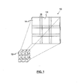
- Shown in Figure 1 is an exemplary display 10 comprising nine projector systems 12 aligned in a 3x3 configuration. To provide a contiguous image, adjacent projector images 14 are partially overlapped, creating what is termed a blend zone 16.
- each projector image 14 is modified to create a blend curve.
- the blend curve represents a transition region from normal light intensity (e.g. 100%) generally closest to the non-overlapped image, to a reduced or faded light intensity (e.g. 0%) generally furthest away from the non-overlapped image.
- a blend multiplier values of 0.0 to 1.0 is applied to the target light intensity based on the video signal of the pixels within the overlap region, thereby modifying the light intensity in accordance with the desired intensity for any one location within the blend curve.
- Intensity NET represents the net light intensity
- Intensity SIGNAL represents the target light intensity based on the video signal (generally termed 'target light intensity')
- B represents the blend multiplier.
- Intensity NET is the resulting modified light intensity within the blend zone.
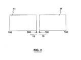
- Figure 2 depicts an exemplary linear blend curve 18 for two projector images 14 configured to be overlapped.
- a blend multiplier is applied to the target light intensity of the pixels to achieve a linear transition from 0% to 100% within the blend zone, starting at the left-most portion of the image.
- a blend multiplier is applied to the target light intensity of the pixels to achieve a linear transition from 0% to 100% within the blend zone, staring at the right-most portion of the image.
- the application of the blend multiplier to each projector image is such that in a composite overlapped image, the total sum light intensity for a pixel location within the blend zone substantially equals 100% of the original video signal intensity.
- a spatial intensity variance is introduced in the form of dithering, into the pixels of each projector image.
- the pixel intensity of locally paired or grouped pixels are spread or varied inversely, such that the sum paired or group variance is close or equal to zero.
- a paired or grouping of pixels will exhibit an average intensity equal to the desired intensity for that particular location in the original image.
- the applied dithering maintains the average blend curve as close as possible to the non-dithered blend.
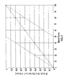
- the maximum allowable variance for the pixel pair is a function of the blend multiplier at that given location within the blend curve, as shown in Figure 3 .
- the spatial intensity variance for an exemplary pixel pair is calculated as follows:
- V max the maximum +/- variance
- Variances that are less than the allowable maximum are represented as fractions thereof (e.g. V +0.5 variance equals a 50% maximum positive variance; V -0.3 variance equals 30% maximum negative variance).
- V +0.5 variance equals a 50% maximum positive variance; V -0.3 variance equals 30% maximum negative variance.
- a variance in pixel intensities is created within defined matrices of pixels, wherein adjacent pairs of pixels (in both horizontal and vertical orientation) average to the desired local intensity (e.g. Intensity NET on application of the blend multiplier).
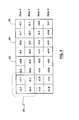
- a schematic representation of an exemplary 2x2 matrix 20 is provided in Figure 4 .
- a first 2x2 matrix 20 provides a V- 0.1 /V +0.1 intensity variance in row 0, and a V +0.1/ V -0.1 intensity variance in row 1, based on the value of the blend multiplier at the location of this first 2x2 matrix.
- the sum variance for all adjacent pixels, whether in vertical or horizontal arrangement is zero.
- the average light intensity for this 2x2 matrix 20 remains substantially the same as the desired local light intensity (e.g. Intensity NET ) of the projected image.
- the intensity variances are V -0.6 /V +0.6 and V -0.7 /V +0.7 , respectively.
- the degree of variance within the allowable maximum variance for a particular group of pixels is randomly selected for each matrix, so as to ensure overall uniformity in the projected image.
- the determination and application of the fraction of variance being applied (V x ) based on the allowable maximum variance can be achieved a number of different ways.
- the area of the blend zone is set, and a value for V x is randomly determined for each 2x2 matrix within the blend zone.
- Exemplary source code for determining V x for 2x2 matrices in a blend zone of size xres and yres is provided as follows: With the determination of V x for each 2x2 matrix within the blend zone, V x is then applied as detailed above for each of Pixel ADJ1 and Pixel ADJ2 .
- the variance applied to the blend multiplier can be inverted in quick succession.
- a target light intensity of 80% with a blend multiplier of 0.6 has a maximum variance (V max ) of 0.4.
- V max provides an adjusted intensity for a pixel pair of 80% and 16%.
- the pixel pair would exhibit a 80% (Pixel ADJ1 ) and 16% (Pixel ADJ2 ) intensity, while in the next frame, the pixel pair would exhibit a 16% (Pixel ADJ1 ) and 80% (Pixel ADJ2 ) intensity.
- dithering patterns due to the introduction of spatial intensity variance would be less visible.
- the fraction of the variance applied (V x ) to the blend multiplier can be changed in quick succession.
- V max maximum variance
- V x in a first frame, V x may be 1.0, while in the next frame, V x may be 0.4.
- the pixel pair in a first frame, the pixel pair would exhibit a 80% (Pixel ADJ1 ) and 16% (Pixel ADJ2 ) intensity, while in the next frame, the pixel pair would exhibit a 60.8% (Pixel ADJ1 ) and 35.2% (Pixel ADJ2 ) intensity.
- dithering patterns due to the introduction of spatial intensity variance would be less visible.
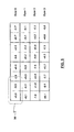
- each image may be adjusted with a random per pixel variance in which the dithering pattern is applied to the locally paired or grouped pixels 40 based on a random per pixel variance limited within the permissible maximum variance.
- each pixel pair 30 arranged in rows 0, 1, 2 and 3 exhibit randomly selected variances.
- the sum of the positive/negative variance is zero, and the average intensity of the pixel pair is equal to the desired local light intensity determined prior to intensity adjustment.
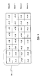
- a 1 st order checkerboard variance pattern may be introduced wherein the dithering pattern is applied to the image based on a repeating 1 st order 2x2 checkerboard variance pattern, as schematically depicted in Figure 6 .
- a repeating 1 st order 2x2 checkerboard variance pattern as schematically depicted in Figure 6 .
- each 2x2 matrix 32 in row 0, pixels are set to a repeating V +1.0 /V -1.0 variance, while in row 1, pixels are set to a repeating V -1.0 /V +1.0 variance.
- This pattern is then repeated in each 2x2 matrix of the projected image.
- the sum of the positive/negative variance for adjacent pixels is zero, and the average intensity of the 2x2 matrix is equal to the desired local light intensity determined for that location prior to intensity adjustment.
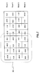
- a 2 nd order checkerboard variance pattern may be implemented, wherein the dithering pattern is applied to the image based on a 2 nd order 4x4 checkerboard variance pattern, as schematically depicted in Figure 7 .
- a first pixel pair in row 0, a first pixel pair is set to a V +1.0 /V -1.0 variance, while a second pixel pair is set to a V +0.5 /V -0.5 variance.
- a first pixel pair is set to a V -1.0 /V +1.0 variance
- a second pixel pair is set to a V -0.5 /V +0.5 variance.
- each 4x4 matrix comprises 4 2x2 matrices. Once again, within each of these 2x2 matrices, the sum of the positive/negative variance for adjacent pixels is zero, and the average intensity of each 2x2 matrix is equal to the desired local light intensity determined for that location prior to intensity adjustment.
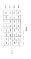
- the 2 nd order checkerboard pattern may be further modified in accordance with the variances shown in Figure 9.
- a first pixel pair in row 0, a first pixel pair is set to a V +1.0 /V -1.0 variance, while a second pixel pair is set to a V +0.5 /V -0.5 variance.
- a first pixel pair is set to a V -1.0 /V +1.0 variance, while a second pixel pair is set to a V -0.5 /V +0.5 variance.
- a first pixel pair is set to a V -0.5 /V +0.5 variance
- a second pixel pair is set to a V -1.0 /V +1.0 variance.
- each 4x4 matrix comprises 4 2x2 matrices.
- the sum of the positive/negative variance for adjacent pixels is zero, and the average intensity of each 2x2 matrix is equal to the desired local light intensity determined for that location prior to intensity adjustment.
- Non-repeating, as well as regular repeating patterns such as the aforementioned checkerboard patterns can give rise to perceivable dither patterns on close inspection, but with rapid inversion of the variances, the likelihood of noticeable dither patterning is reduced.
- the visual artefacts noticed in the blend zone of two adjacently positioned projectors are particularly noticeable with generally solid images. Where projected images are generally random, such as in the projection of leaves on a tree, the visual artefacts in the blend zone are generally less pronounced. As such, in some embodiments, the application of spatial intensity variance is restricted to instances where the blend zone comprises a substantially solid/uniform image (e.g. a solid colour background, a blue sky, etc...), or generally, to areas of the blend zone having a higher probability of producing such visual artefacts.
- a substantially solid/uniform image e.g. a solid colour background, a blue sky, etc.
- a display comprises two projection systems.
- the following is applicable for reducing artefacts in the blend zone of any number of adjacently positioned projection images wherein at least a portion of these images overlap.
- the projected image within the blend zone of two partially overlapping images is analyzed to determine the applicable blend multiplier to achieve the desired blend curve.
- the maximum variance (V max) is determined.
- the applied variance is a fraction of the maximum variance
- a random number generator is used to generate the fraction (V x ) to be applied.
- the target light intensity is then adjusted according to the blend multiplier, taking into account V max and the fraction thereof to be applied.
- the sum of the positive intensity variance and the negative intensity variance within the pixel group should equal zero. This treatment is applied throughout the blend zone, in particular in instances where the images have a high probability of producing visual artefacts.
- edge blending technology has been largely described within the framework of regularly shaped blend zones arising from two or more projectors (as depicted in Figure 1 ), the actual shape and complexity of the blend zones may vary. For example, in instances where two projected images are not substantially rectilinear, the blend zone therebetween may comprise an irregular/complex shape.
- the edge blending technology described here is intended to be applicable to blend zones of irregular/complex shape.
- transition region of the blend zone has been described herein as linear, nonlinear transition regions are also contemplated.
- the applied variance may be any value up to the maximum permitted variance, in certain applications, the applied variance may be limited.
- the applied variance may be limited to V +0.1 /V -0.1 In other words, the applied variance may be limited to 10% of the maximal permissible variance.
- the limitation may be case specific, with the limitation being selected from a range of 0% to 100% of maximum permissible variance.
- the degree of variance can be randomly selected, spatial intensity variance may also be applied in a non-random manner.
- the variance may be pseudo-random, or based on a pattern that would 'appear' random to a viewer, but is technically deterministic.
- the spatial intensity variance methodology described herein can be applied to other image projection technologies where PWM is used create a projected image from a plurality of projectors.
Landscapes
- Engineering & Computer Science (AREA)
- Multimedia (AREA)
- Signal Processing (AREA)
- Theoretical Computer Science (AREA)
- Computer Hardware Design (AREA)
- General Physics & Mathematics (AREA)
- Physics & Mathematics (AREA)
- Control Of Indicators Other Than Cathode Ray Tubes (AREA)
- Projection Apparatus (AREA)
- Liquid Crystal Display Device Control (AREA)
- Controls And Circuits For Display Device (AREA)
- Transforming Electric Information Into Light Information (AREA)
- Video Image Reproduction Devices For Color Tv Systems (AREA)
- Facsimile Image Signal Circuits (AREA)
Applications Claiming Priority (1)
| Application Number | Priority Date | Filing Date | Title |
|---|---|---|---|
| US12/436,477 US8289346B2 (en) | 2009-05-06 | 2009-05-06 | DLP edge blending artefact reduction |
Publications (2)
| Publication Number | Publication Date |
|---|---|
| EP2249560A1 true EP2249560A1 (de) | 2010-11-10 |
| EP2249560B1 EP2249560B1 (de) | 2012-02-08 |
Family
ID=42315555
Family Applications (1)
| Application Number | Title | Priority Date | Filing Date |
|---|---|---|---|
| EP10161178A Active EP2249560B1 (de) | 2009-05-06 | 2010-04-27 | Reduzierung der DLP-Edge-Blending-Artefakte |
Country Status (4)
| Country | Link |
|---|---|
| US (3) | US8289346B2 (de) |
| EP (1) | EP2249560B1 (de) |
| JP (1) | JP2010262287A (de) |
| AT (1) | ATE545278T1 (de) |
Cited By (2)
| Publication number | Priority date | Publication date | Assignee | Title |
|---|---|---|---|---|
| CN103595926B (zh) * | 2012-08-15 | 2017-06-13 | 无锡思朗电子科技有限公司 | 一种分布式图像边缘融合处理系统 |
| CN107862649A (zh) * | 2017-10-11 | 2018-03-30 | 中铁第四勘察设计院集团有限公司 | 一种基于仿真视景系统的gpu加速多通道融合方法及系统 |
Families Citing this family (22)
| Publication number | Priority date | Publication date | Assignee | Title |
|---|---|---|---|---|
| US8289346B2 (en) | 2009-05-06 | 2012-10-16 | Christie Digital Systems Usa, Inc. | DLP edge blending artefact reduction |
| US8619094B2 (en) * | 2011-01-07 | 2013-12-31 | Sony Computer Entertainment America Llc | Morphological anti-aliasing (MLAA) of a re-projection of a two-dimensional image |
| WO2012094077A1 (en) | 2011-01-07 | 2012-07-12 | Sony Computer Entertainment America Llc | Multi-sample resolving of re-projection of two-dimensional image |
| US9183670B2 (en) | 2011-01-07 | 2015-11-10 | Sony Computer Entertainment America, LLC | Multi-sample resolving of re-projection of two-dimensional image |
| US8514225B2 (en) | 2011-01-07 | 2013-08-20 | Sony Computer Entertainment America Llc | Scaling pixel depth values of user-controlled virtual object in three-dimensional scene |
| US9041774B2 (en) | 2011-01-07 | 2015-05-26 | Sony Computer Entertainment America, LLC | Dynamic adjustment of predetermined three-dimensional video settings based on scene content |
| WO2015195920A1 (en) | 2014-06-20 | 2015-12-23 | Carbon3D, Inc. | Three-dimensional printing method using increased light intensity and apparatus therefore |
| ES2711849T3 (es) | 2014-06-20 | 2019-05-07 | Carbon Inc | Impresión tridimensional con alimentación recíproca de líquido polimerizable |
| WO2015195909A1 (en) | 2014-06-20 | 2015-12-23 | Carbon3D, Inc. | Three-dimensional printing using tiled light engines |
| AU2015280283B2 (en) | 2014-06-23 | 2019-05-02 | Carbon, Inc. | Methods of producing three-dimensional objects from materials having multiple mechanisms of hardening |
| US11390062B2 (en) | 2014-08-12 | 2022-07-19 | Carbon, Inc. | Three-dimensional printing with supported build plates |
| EP3240671B1 (de) | 2014-12-31 | 2020-12-16 | Carbon, Inc. | Dreidimensionales drucken von objekten mit belüftungsöffnungen |
| WO2016112090A1 (en) | 2015-01-07 | 2016-07-14 | Carbon3D, Inc. | Microfluidic devices and methods of making the same |
| WO2016145050A1 (en) | 2015-03-10 | 2016-09-15 | Carbon3D, Inc. | Microfluidic devices having flexible features and methods of making the same |
| WO2016149097A1 (en) | 2015-03-13 | 2016-09-22 | Carbon3D, Inc. | Three-dimensional printing with reduced pressure build plate unit |
| US10792856B2 (en) | 2015-03-13 | 2020-10-06 | Carbon, Inc. | Three-dimensional printing with flexible build plates |
| WO2016149151A1 (en) | 2015-03-13 | 2016-09-22 | Carbon3D, Inc. | Three-dimensional printing with concurrent delivery of different polymerizable liquids |
| WO2017112682A1 (en) | 2015-12-22 | 2017-06-29 | Carbon, Inc. | Fabrication of compound products from multiple intermediates by additive manufacturing with dual cure resins |
| WO2017112521A1 (en) | 2015-12-22 | 2017-06-29 | Carbon, Inc. | Production of flexible products by additive manufacturing with dual cure resins |
| EP3341792A1 (de) | 2015-12-22 | 2018-07-04 | Carbon, Inc. | Doppelvorläufer-harzsysteme zur generativen fertigung mit doppelhärtungsharzen |
| US10647054B2 (en) | 2015-12-22 | 2020-05-12 | Carbon, Inc. | Accelerants for additive manufacturing with dual cure resins |
| JP2024522965A (ja) | 2021-04-26 | 2024-06-25 | ローレンス リヴァーモア ナショナル セキュリティ,エルエルシー | ステレオリソグラフィシステムの較正の方法 |
Citations (6)
| Publication number | Priority date | Publication date | Assignee | Title |
|---|---|---|---|---|
| US5980044A (en) * | 1998-09-16 | 1999-11-09 | Evans & Sutherland Computer Corp. | Area of interest display system with image combining using error dithering |
| WO2001041455A1 (en) * | 1999-11-29 | 2001-06-07 | Barco N.V. | Optical soft edge matching method for light valve projectors |
| KR20070024049A (ko) * | 2005-08-26 | 2007-03-02 | 이화여자대학교 산학협력단 | 디스플레이의 트란스포머 함수를 측정하는 방법 및 이를이용한 타일 디스플레이의 컬러보정방법 |
| US20070188719A1 (en) * | 2006-02-15 | 2007-08-16 | Mersive Technologies, Llc | Multi-projector intensity blending system |
| US20080024683A1 (en) * | 2006-07-31 | 2008-01-31 | Niranjan Damera-Venkata | Overlapped multi-projector system with dithering |
| US7339625B2 (en) * | 2004-06-28 | 2008-03-04 | Barco N.V. | Optical and electrical blending of display images |
Family Cites Families (8)
| Publication number | Priority date | Publication date | Assignee | Title |
|---|---|---|---|---|
| JPH03243931A (ja) * | 1990-02-22 | 1991-10-30 | Toshiba Corp | 投射型表示装置の輝度補正回路 |
| US6924816B2 (en) * | 2000-03-17 | 2005-08-02 | Sun Microsystems, Inc. | Compensating for the chromatic distortion of displayed images |
| CA2412418C (en) * | 2000-06-13 | 2006-08-08 | Panoram Technologies, Inc. | Method and apparatus for seamless integration of multiple video projectors |
| JP4574819B2 (ja) * | 2000-08-30 | 2010-11-04 | パナソニック株式会社 | ビデオプロジェクタ装置 |
| US7171057B1 (en) * | 2002-10-16 | 2007-01-30 | Adobe Systems Incorporated | Image blending using non-affine interpolation |
| US7292207B1 (en) * | 2004-08-27 | 2007-11-06 | Sun Microsystems, Inc. | Computing blending functions for the tiling of overlapped video projectors |
| US7450137B2 (en) * | 2005-02-18 | 2008-11-11 | Hewlett-Packard Development Company, L.P. | System and method for blending images |
| US8289346B2 (en) | 2009-05-06 | 2012-10-16 | Christie Digital Systems Usa, Inc. | DLP edge blending artefact reduction |
-
2009
- 2009-05-06 US US12/436,477 patent/US8289346B2/en active Active
-
2010
- 2010-04-27 JP JP2010101790A patent/JP2010262287A/ja active Pending
- 2010-04-27 AT AT10161178T patent/ATE545278T1/de active
- 2010-04-27 EP EP10161178A patent/EP2249560B1/de active Active
-
2012
- 2012-09-14 US US13/617,534 patent/US8446431B2/en active Active
-
2013
- 2013-05-17 US US13/896,625 patent/US8749581B2/en active Active
Patent Citations (6)
| Publication number | Priority date | Publication date | Assignee | Title |
|---|---|---|---|---|
| US5980044A (en) * | 1998-09-16 | 1999-11-09 | Evans & Sutherland Computer Corp. | Area of interest display system with image combining using error dithering |
| WO2001041455A1 (en) * | 1999-11-29 | 2001-06-07 | Barco N.V. | Optical soft edge matching method for light valve projectors |
| US7339625B2 (en) * | 2004-06-28 | 2008-03-04 | Barco N.V. | Optical and electrical blending of display images |
| KR20070024049A (ko) * | 2005-08-26 | 2007-03-02 | 이화여자대학교 산학협력단 | 디스플레이의 트란스포머 함수를 측정하는 방법 및 이를이용한 타일 디스플레이의 컬러보정방법 |
| US20070188719A1 (en) * | 2006-02-15 | 2007-08-16 | Mersive Technologies, Llc | Multi-projector intensity blending system |
| US20080024683A1 (en) * | 2006-07-31 | 2008-01-31 | Niranjan Damera-Venkata | Overlapped multi-projector system with dithering |
Cited By (3)
| Publication number | Priority date | Publication date | Assignee | Title |
|---|---|---|---|---|
| CN103595926B (zh) * | 2012-08-15 | 2017-06-13 | 无锡思朗电子科技有限公司 | 一种分布式图像边缘融合处理系统 |
| CN107862649A (zh) * | 2017-10-11 | 2018-03-30 | 中铁第四勘察设计院集团有限公司 | 一种基于仿真视景系统的gpu加速多通道融合方法及系统 |
| CN107862649B (zh) * | 2017-10-11 | 2021-04-30 | 中铁第四勘察设计院集团有限公司 | 一种基于仿真视景系统的gpu加速多通道融合方法及系统 |
Also Published As
| Publication number | Publication date |
|---|---|
| JP2010262287A (ja) | 2010-11-18 |
| US20100283794A1 (en) | 2010-11-11 |
| US20130050257A1 (en) | 2013-02-28 |
| ATE545278T1 (de) | 2012-02-15 |
| US8289346B2 (en) | 2012-10-16 |
| US20140022280A1 (en) | 2014-01-23 |
| EP2249560B1 (de) | 2012-02-08 |
| US8446431B2 (en) | 2013-05-21 |
| US8749581B2 (en) | 2014-06-10 |
Similar Documents
| Publication | Publication Date | Title |
|---|---|---|
| EP2249560B1 (de) | Reduzierung der DLP-Edge-Blending-Artefakte | |
| CN1244228C (zh) | 利用光学函数发生器的无缝平铺显示器的电子校准 | |
| JP7055660B2 (ja) | ディスプレイ及びプロジェクタ | |
| CN100459677C (zh) | 图像显示的控制方法以及控制装置 | |
| US6774916B2 (en) | Contour mitigation using parallel blue noise dithering system | |
| CN112119449A (zh) | 图像处理装置、显示装置和图像处理方法 | |
| CN100547651C (zh) | 图像处理装置、图像显示装置和图像处理方法 | |
| JP2006153914A (ja) | 液晶プロジェクタ装置 | |
| KR101096908B1 (ko) | 최소 노이즈를 갖는 픽셀 시프트 디스플레이 | |
| US20060164443A1 (en) | Modulating spatial light modulator with logically OR'ed values of bit planes | |
| US20100177129A1 (en) | Artifact reduction in optical scanning displays | |
| EP1889250B1 (de) | Vorrichtung zur bildverarbeitung in räumlich lichtmodulierten anzeigesystemen | |
| JP5586831B2 (ja) | パルス幅変調(pwm)ディスプレイにおけるダークノイズ削減のためのシステムおよび方法 | |
| US20070013717A1 (en) | Displaying non-linear images on linear displays | |
| US20100177123A1 (en) | Edge reproduction in optical scanning displays | |
| CN118864299B (zh) | 图像处理方法、装置、非易失性存储介质和计算机设备 | |
| JP5665791B2 (ja) | 空間光変調されたディスプレイ・システムにおいて画像を処理するための装置および方法 | |
| KR100510652B1 (ko) | 디엘피 시스템의 비트 플레인 분할 방법 | |
| CN104360487B (zh) | 一种激光投影显示方法及装置 | |
| JP2007129748A (ja) | 画像表示制御方法、画像表示制御装置および画像表示制御プログラム |
Legal Events
| Date | Code | Title | Description |
|---|---|---|---|
| PUAI | Public reference made under article 153(3) epc to a published international application that has entered the european phase |
Free format text: ORIGINAL CODE: 0009012 |
|
| AK | Designated contracting states |
Kind code of ref document: A1 Designated state(s): AT BE BG CH CY CZ DE DK EE ES FI FR GB GR HR HU IE IS IT LI LT LU LV MC MK MT NL NO PL PT RO SE SI SK SM TR |
|
| AX | Request for extension of the european patent |
Extension state: AL BA ME RS |
|
| 17P | Request for examination filed |
Effective date: 20110329 |
|
| GRAP | Despatch of communication of intention to grant a patent |
Free format text: ORIGINAL CODE: EPIDOSNIGR1 |
|
| RIC1 | Information provided on ipc code assigned before grant |
Ipc: H04N 5/74 20060101AFI20110713BHEP Ipc: G03B 21/00 20060101ALI20110713BHEP |
|
| RIN1 | Information on inventor provided before grant (corrected) |
Inventor name: PRIEDE, JORDAN EVALDS HUXLEY Inventor name: PARACHONIAK, JASON PATRICK |
|
| GRAS | Grant fee paid |
Free format text: ORIGINAL CODE: EPIDOSNIGR3 |
|
| GRAA | (expected) grant |
Free format text: ORIGINAL CODE: 0009210 |
|
| AK | Designated contracting states |
Kind code of ref document: B1 Designated state(s): AT BE BG CH CY CZ DE DK EE ES FI FR GB GR HR HU IE IS IT LI LT LU LV MC MK MT NL NO PL PT RO SE SI SK SM TR |
|
| REG | Reference to a national code |
Ref country code: GB Ref legal event code: FG4D |
|
| REG | Reference to a national code |
Ref country code: AT Ref legal event code: REF Ref document number: 545278 Country of ref document: AT Kind code of ref document: T Effective date: 20120215 Ref country code: CH Ref legal event code: EP |
|
| REG | Reference to a national code |
Ref country code: DE Ref legal event code: R096 Ref document number: 602010000796 Country of ref document: DE Effective date: 20120412 |
|
| REG | Reference to a national code |
Ref country code: NL Ref legal event code: VDEP Effective date: 20120208 |
|
| LTIE | Lt: invalidation of european patent or patent extension |
Effective date: 20120208 |
|
| PG25 | Lapsed in a contracting state [announced via postgrant information from national office to epo] |
Ref country code: LT Free format text: LAPSE BECAUSE OF FAILURE TO SUBMIT A TRANSLATION OF THE DESCRIPTION OR TO PAY THE FEE WITHIN THE PRESCRIBED TIME-LIMIT Effective date: 20120208 Ref country code: NO Free format text: LAPSE BECAUSE OF FAILURE TO SUBMIT A TRANSLATION OF THE DESCRIPTION OR TO PAY THE FEE WITHIN THE PRESCRIBED TIME-LIMIT Effective date: 20120508 Ref country code: NL Free format text: LAPSE BECAUSE OF FAILURE TO SUBMIT A TRANSLATION OF THE DESCRIPTION OR TO PAY THE FEE WITHIN THE PRESCRIBED TIME-LIMIT Effective date: 20120208 Ref country code: IS Free format text: LAPSE BECAUSE OF FAILURE TO SUBMIT A TRANSLATION OF THE DESCRIPTION OR TO PAY THE FEE WITHIN THE PRESCRIBED TIME-LIMIT Effective date: 20120608 Ref country code: HR Free format text: LAPSE BECAUSE OF FAILURE TO SUBMIT A TRANSLATION OF THE DESCRIPTION OR TO PAY THE FEE WITHIN THE PRESCRIBED TIME-LIMIT Effective date: 20120208 |
|
| PG25 | Lapsed in a contracting state [announced via postgrant information from national office to epo] |
Ref country code: LV Free format text: LAPSE BECAUSE OF FAILURE TO SUBMIT A TRANSLATION OF THE DESCRIPTION OR TO PAY THE FEE WITHIN THE PRESCRIBED TIME-LIMIT Effective date: 20120208 Ref country code: FI Free format text: LAPSE BECAUSE OF FAILURE TO SUBMIT A TRANSLATION OF THE DESCRIPTION OR TO PAY THE FEE WITHIN THE PRESCRIBED TIME-LIMIT Effective date: 20120208 Ref country code: GR Free format text: LAPSE BECAUSE OF FAILURE TO SUBMIT A TRANSLATION OF THE DESCRIPTION OR TO PAY THE FEE WITHIN THE PRESCRIBED TIME-LIMIT Effective date: 20120509 Ref country code: PL Free format text: LAPSE BECAUSE OF FAILURE TO SUBMIT A TRANSLATION OF THE DESCRIPTION OR TO PAY THE FEE WITHIN THE PRESCRIBED TIME-LIMIT Effective date: 20120208 Ref country code: PT Free format text: LAPSE BECAUSE OF FAILURE TO SUBMIT A TRANSLATION OF THE DESCRIPTION OR TO PAY THE FEE WITHIN THE PRESCRIBED TIME-LIMIT Effective date: 20120608 Ref country code: BE Free format text: LAPSE BECAUSE OF FAILURE TO SUBMIT A TRANSLATION OF THE DESCRIPTION OR TO PAY THE FEE WITHIN THE PRESCRIBED TIME-LIMIT Effective date: 20120208 |
|
| REG | Reference to a national code |
Ref country code: AT Ref legal event code: MK05 Ref document number: 545278 Country of ref document: AT Kind code of ref document: T Effective date: 20120208 |
|
| PG25 | Lapsed in a contracting state [announced via postgrant information from national office to epo] |
Ref country code: CY Free format text: LAPSE BECAUSE OF FAILURE TO SUBMIT A TRANSLATION OF THE DESCRIPTION OR TO PAY THE FEE WITHIN THE PRESCRIBED TIME-LIMIT Effective date: 20120208 |
|
| PG25 | Lapsed in a contracting state [announced via postgrant information from national office to epo] |
Ref country code: CZ Free format text: LAPSE BECAUSE OF FAILURE TO SUBMIT A TRANSLATION OF THE DESCRIPTION OR TO PAY THE FEE WITHIN THE PRESCRIBED TIME-LIMIT Effective date: 20120208 Ref country code: RO Free format text: LAPSE BECAUSE OF FAILURE TO SUBMIT A TRANSLATION OF THE DESCRIPTION OR TO PAY THE FEE WITHIN THE PRESCRIBED TIME-LIMIT Effective date: 20120208 Ref country code: SE Free format text: LAPSE BECAUSE OF FAILURE TO SUBMIT A TRANSLATION OF THE DESCRIPTION OR TO PAY THE FEE WITHIN THE PRESCRIBED TIME-LIMIT Effective date: 20120208 Ref country code: SI Free format text: LAPSE BECAUSE OF FAILURE TO SUBMIT A TRANSLATION OF THE DESCRIPTION OR TO PAY THE FEE WITHIN THE PRESCRIBED TIME-LIMIT Effective date: 20120208 Ref country code: EE Free format text: LAPSE BECAUSE OF FAILURE TO SUBMIT A TRANSLATION OF THE DESCRIPTION OR TO PAY THE FEE WITHIN THE PRESCRIBED TIME-LIMIT Effective date: 20120208 Ref country code: DK Free format text: LAPSE BECAUSE OF FAILURE TO SUBMIT A TRANSLATION OF THE DESCRIPTION OR TO PAY THE FEE WITHIN THE PRESCRIBED TIME-LIMIT Effective date: 20120208 |
|
| PG25 | Lapsed in a contracting state [announced via postgrant information from national office to epo] |
Ref country code: SK Free format text: LAPSE BECAUSE OF FAILURE TO SUBMIT A TRANSLATION OF THE DESCRIPTION OR TO PAY THE FEE WITHIN THE PRESCRIBED TIME-LIMIT Effective date: 20120208 Ref country code: MC Free format text: LAPSE BECAUSE OF NON-PAYMENT OF DUE FEES Effective date: 20120430 |
|
| PLBE | No opposition filed within time limit |
Free format text: ORIGINAL CODE: 0009261 |
|
| STAA | Information on the status of an ep patent application or granted ep patent |
Free format text: STATUS: NO OPPOSITION FILED WITHIN TIME LIMIT |
|
| 26N | No opposition filed |
Effective date: 20121109 |
|
| PG25 | Lapsed in a contracting state [announced via postgrant information from national office to epo] |
Ref country code: AT Free format text: LAPSE BECAUSE OF FAILURE TO SUBMIT A TRANSLATION OF THE DESCRIPTION OR TO PAY THE FEE WITHIN THE PRESCRIBED TIME-LIMIT Effective date: 20120208 |
|
| PG25 | Lapsed in a contracting state [announced via postgrant information from national office to epo] |
Ref country code: MK Free format text: LAPSE BECAUSE OF FAILURE TO SUBMIT A TRANSLATION OF THE DESCRIPTION OR TO PAY THE FEE WITHIN THE PRESCRIBED TIME-LIMIT Effective date: 20120208 |
|
| REG | Reference to a national code |
Ref country code: DE Ref legal event code: R097 Ref document number: 602010000796 Country of ref document: DE Effective date: 20121109 |
|
| PG25 | Lapsed in a contracting state [announced via postgrant information from national office to epo] |
Ref country code: ES Free format text: LAPSE BECAUSE OF FAILURE TO SUBMIT A TRANSLATION OF THE DESCRIPTION OR TO PAY THE FEE WITHIN THE PRESCRIBED TIME-LIMIT Effective date: 20120519 Ref country code: IE Free format text: LAPSE BECAUSE OF NON-PAYMENT OF DUE FEES Effective date: 20120427 |
|
| PG25 | Lapsed in a contracting state [announced via postgrant information from national office to epo] |
Ref country code: BG Free format text: LAPSE BECAUSE OF FAILURE TO SUBMIT A TRANSLATION OF THE DESCRIPTION OR TO PAY THE FEE WITHIN THE PRESCRIBED TIME-LIMIT Effective date: 20120508 Ref country code: MT Free format text: LAPSE BECAUSE OF FAILURE TO SUBMIT A TRANSLATION OF THE DESCRIPTION OR TO PAY THE FEE WITHIN THE PRESCRIBED TIME-LIMIT Effective date: 20120208 |
|
| PG25 | Lapsed in a contracting state [announced via postgrant information from national office to epo] |
Ref country code: TR Free format text: LAPSE BECAUSE OF FAILURE TO SUBMIT A TRANSLATION OF THE DESCRIPTION OR TO PAY THE FEE WITHIN THE PRESCRIBED TIME-LIMIT Effective date: 20120208 |
|
| PG25 | Lapsed in a contracting state [announced via postgrant information from national office to epo] |
Ref country code: LU Free format text: LAPSE BECAUSE OF NON-PAYMENT OF DUE FEES Effective date: 20120427 Ref country code: SM Free format text: LAPSE BECAUSE OF FAILURE TO SUBMIT A TRANSLATION OF THE DESCRIPTION OR TO PAY THE FEE WITHIN THE PRESCRIBED TIME-LIMIT Effective date: 20120208 |
|
| PG25 | Lapsed in a contracting state [announced via postgrant information from national office to epo] |
Ref country code: HU Free format text: LAPSE BECAUSE OF FAILURE TO SUBMIT A TRANSLATION OF THE DESCRIPTION OR TO PAY THE FEE WITHIN THE PRESCRIBED TIME-LIMIT Effective date: 20100427 |
|
| REG | Reference to a national code |
Ref country code: CH Ref legal event code: PL |
|
| PG25 | Lapsed in a contracting state [announced via postgrant information from national office to epo] |
Ref country code: CH Free format text: LAPSE BECAUSE OF NON-PAYMENT OF DUE FEES Effective date: 20140430 Ref country code: LI Free format text: LAPSE BECAUSE OF NON-PAYMENT OF DUE FEES Effective date: 20140430 |
|
| REG | Reference to a national code |
Ref country code: FR Ref legal event code: PLFP Year of fee payment: 7 |
|
| REG | Reference to a national code |
Ref country code: FR Ref legal event code: PLFP Year of fee payment: 8 |
|
| REG | Reference to a national code |
Ref country code: FR Ref legal event code: PLFP Year of fee payment: 9 |
|
| REG | Reference to a national code |
Ref country code: FR Ref legal event code: PLFP Year of fee payment: 14 |
|
| P01 | Opt-out of the competence of the unified patent court (upc) registered |
Effective date: 20230428 |
|
| PGFP | Annual fee paid to national office [announced via postgrant information from national office to epo] |
Ref country code: GB Payment date: 20260408 Year of fee payment: 17 |
|
| PGFP | Annual fee paid to national office [announced via postgrant information from national office to epo] |
Ref country code: IT Payment date: 20260422 Year of fee payment: 17 |
|
| PGFP | Annual fee paid to national office [announced via postgrant information from national office to epo] |
Ref country code: DE Payment date: 20260408 Year of fee payment: 17 |
|
| PGFP | Annual fee paid to national office [announced via postgrant information from national office to epo] |
Ref country code: FR Payment date: 20260401 Year of fee payment: 17 |