EP2249525B1 - Aufbau einer Traffic-Engineered-Verbindung über Ressourcendomains zum Datentransport - Google Patents
Aufbau einer Traffic-Engineered-Verbindung über Ressourcendomains zum Datentransport Download PDFInfo
- Publication number
- EP2249525B1 EP2249525B1 EP20090305402 EP09305402A EP2249525B1 EP 2249525 B1 EP2249525 B1 EP 2249525B1 EP 20090305402 EP20090305402 EP 20090305402 EP 09305402 A EP09305402 A EP 09305402A EP 2249525 B1 EP2249525 B1 EP 2249525B1
- Authority
- EP
- European Patent Office
- Prior art keywords
- service
- inter
- service provider
- connection
- identifier
- Prior art date
- Legal status (The legal status is an assumption and is not a legal conclusion. Google has not performed a legal analysis and makes no representation as to the accuracy of the status listed.)
- Not-in-force
Links
Images


Classifications
-
- H—ELECTRICITY
- H04—ELECTRIC COMMUNICATION TECHNIQUE
- H04L—TRANSMISSION OF DIGITAL INFORMATION, e.g. TELEGRAPHIC COMMUNICATION
- H04L45/00—Routing or path finding of packets in data switching networks
- H04L45/52—Multiprotocol routers
-
- H—ELECTRICITY
- H04—ELECTRIC COMMUNICATION TECHNIQUE
- H04L—TRANSMISSION OF DIGITAL INFORMATION, e.g. TELEGRAPHIC COMMUNICATION
- H04L45/00—Routing or path finding of packets in data switching networks
- H04L45/02—Topology update or discovery
- H04L45/04—Interdomain routing, e.g. hierarchical routing
-
- H—ELECTRICITY
- H04—ELECTRIC COMMUNICATION TECHNIQUE
- H04L—TRANSMISSION OF DIGITAL INFORMATION, e.g. TELEGRAPHIC COMMUNICATION
- H04L45/00—Routing or path finding of packets in data switching networks
- H04L45/42—Centralised routing
-
- H—ELECTRICITY
- H04—ELECTRIC COMMUNICATION TECHNIQUE
- H04L—TRANSMISSION OF DIGITAL INFORMATION, e.g. TELEGRAPHIC COMMUNICATION
- H04L45/00—Routing or path finding of packets in data switching networks
- H04L45/50—Routing or path finding of packets in data switching networks using label swapping, e.g. multi-protocol label switch [MPLS]
-
- H—ELECTRICITY
- H04—ELECTRIC COMMUNICATION TECHNIQUE
- H04L—TRANSMISSION OF DIGITAL INFORMATION, e.g. TELEGRAPHIC COMMUNICATION
- H04L45/00—Routing or path finding of packets in data switching networks
- H04L45/64—Routing or path finding of packets in data switching networks using an overlay routing layer
-
- H—ELECTRICITY
- H04—ELECTRIC COMMUNICATION TECHNIQUE
- H04L—TRANSMISSION OF DIGITAL INFORMATION, e.g. TELEGRAPHIC COMMUNICATION
- H04L47/00—Traffic control in data switching networks
- H04L47/10—Flow control; Congestion control
- H04L47/12—Avoiding congestion; Recovering from congestion
- H04L47/125—Avoiding congestion; Recovering from congestion by balancing the load, e.g. traffic engineering
-
- H—ELECTRICITY
- H04—ELECTRIC COMMUNICATION TECHNIQUE
- H04L—TRANSMISSION OF DIGITAL INFORMATION, e.g. TELEGRAPHIC COMMUNICATION
- H04L47/00—Traffic control in data switching networks
- H04L47/70—Admission control; Resource allocation
-
- H—ELECTRICITY
- H04—ELECTRIC COMMUNICATION TECHNIQUE
- H04L—TRANSMISSION OF DIGITAL INFORMATION, e.g. TELEGRAPHIC COMMUNICATION
- H04L47/00—Traffic control in data switching networks
- H04L47/70—Admission control; Resource allocation
- H04L47/78—Architectures of resource allocation
- H04L47/782—Hierarchical allocation of resources, e.g. involving a hierarchy of local and centralised entities
-
- H—ELECTRICITY
- H04—ELECTRIC COMMUNICATION TECHNIQUE
- H04L—TRANSMISSION OF DIGITAL INFORMATION, e.g. TELEGRAPHIC COMMUNICATION
- H04L47/00—Traffic control in data switching networks
- H04L47/70—Admission control; Resource allocation
- H04L47/82—Miscellaneous aspects
- H04L47/825—Involving tunnels, e.g. MPLS
Definitions
- the invention relates to the technical field of inter-carrier telecommunications, i.e. telecommunications involving multiple service providers. More precisely, the invention relates to traffic-engineered connections across multiple resource domains owned by multiple service providers.
- Telecommunication service providers are able to provide data services across their networks.
- data services include multimedia connection services, synchronization distribution and signalling.
- service providers can contract data transport services from other service providers.
- a service provider who wishes to provide global IP virtual private network (VPN) services might contract transport services from access providers to reach enterprise sites that are not directly connected to the service provider's domain.
- VPN virtual private network
- EP-A-1599 000 discloses a method for distributing labels between domains of different technologies or administrations.
- Each label includes a Service label having end-to-end consistency, and a Local label used by each domain.
- EP-A-1089517 discloses a method for establishing connections across a communication network.
- the invention provides a method for establishing a traffic-engineered connection across resource domains for data transport, each of the resource domains being owned by an associated service provider, the method comprising:
- the inter-carrier communication resource identifier indicates communication resources at an inter-carrier interface that make it possible to concatenate two intra-domain connection segments embodying adjacent service elements in the chain.
- concatenation is achieved by transferring the resource identifier through a service layer without relying on signalling protocols, which avoids using signalling protocols at inter-carrier interfaces.
- issues related to signalling message exchange between different domains can be avoided, such as inter-operability between the protocol stacks of each domain or policy rule synchronization between the domains.
- the method may comprise one or more of the following features.
- the inter-carrier communication resource identifier is sent to the service agent within a confirmation message indicating an availability of the first connection segment.
- the inter-carrier communication resource identifier is transferred by the service agent within an activation request for requesting the second service provider to establish a second connection segment embodying the adjacent service element.
- the first service provider selects the first connection segment among a set of pre-computed connection segments embodying the service element.
- the service provider pre-computes and stores one or more connection segments suitable for embodying the service element. This embodiment allows to speed up the connection segment selection. Some or all of the service providers can operate in this way.
- the inter-carrier communication resource identifier may comprise, but is not limited to, any of the following information:
- the service agent determines desired performance parameters for the connection and determines the chain of service elements as a function of the connectivity attributes of the service elements so as to match the desired performance parameters.
- performance parameters may include bandwidth, delay, transmission protocols, transport protocols and others.
- the service agent determines a service identifier for the connection and communicates the service identifier to the service providers associated to the service elements in the chain and the service providers associate the service identifier to connection segments embodying the service elements.
- Service element edges may be specified in diverse ways.
- service element edges are identified at a detailed level, e.g. at border node level or inter-carrier interface level. With such detailed service element edges, it may be possible to ascertain the existence of one or more inter-carrier interfaces between service element edges even before the service elements are instantiated and an intra-domain path of a connection segment is selected (e.g. during the composition phase).
- service element edges are identified as border nodes and the service agent determines the chain of adjacent service elements as a function of border node adjacencies.
- border nodes at the edges of a service element are specified in the service element and adjacencies between the border nodes of the respective service elements are taken into account by the service agent.
- information about border node adjacencies can be made available to the service agent in diverse manners, e.g. through exterior gateway protocol engines such as BGP, or configuration files or in the service elements.
- Embodiments with detailed service element edges make it possible to select multiple connection segments embodying multiple service elements of the chain in parallel with some guarantee that the resulting connection segments will be connectable through an inter-carrier interface between end points of the resulting connection segments, e.g. border nodes of the associated resource domains.
- the service agent requests in parallel the first service provider associated to a service element in the chain and the second service provider associated to an adjacent service element in the chain to select respective connection segments between the border nodes identified in the respective service elements.
- service element edges may be specified at a more abstracted level, e.g. at a domain level.
- service element edges are identified as neighbour resource domains. Such abstraction may improve confidentiality of topology information relative to each resource domain.
- service element edges specified as neighbour resource domains allow for more flexibility in the connection path computation since any of the border nodes interfacing with the cited neighbour resource domain can be considered for establishing a connection segment embodying the service element.
- the service agent may not be able to define the end points of a connection segment already at the step of determining the chain of adjacent service elements (i.e. composition step). Therefore, an issue arises to ascertain the existence of an inter-carrier interface between the respective connection segments.
- the first and second connection segments are selected in a sequential manner so as to satisfy this constraint.
- the service agent transfers the inter-carrier communication resource identifier to the second service provider within a request for selecting a second connection segment embodying the adjacent service element in the chain, and the second service provider selects the second connection segment as a function of the inter-carrier communication resource identifier so that the second connection segment ends at the inter-carrier interface indicated by the inter-carrier communication resource identifier.
- the invention provides also a service agent for establishing a traffic-engineered connection across resource domains for data transport, each of the resource domains being owned by an associated service provider, the service agent comprising a processing module adapted to:
- the invention provides also a service provider system for a service provider owning a resource domain and participating in a service provider alliance to establish inter-domain connections through the resource domain, the service provider system comprising:
- the invention provides also a service provider system for a service provider owning a resource domain and participating in a service provider alliance to establish inter-domain connections through the resource domain, the service provider system comprising:
- aspects of the invention are based on the observation that configuring inter-carrier connections through an abstracted service layer involves multiple communications between service providers, i.e. domain owners and a service agent in charge of composing a service from multiple elements. Aspects of the invention result in an efficient use of such communications to achieve inter-carrier connection establishment in a fast, reliable and/or secure way.
- a connection refers to a communication channel through a communication system.
- a path refers to a sequence of links and nodes suitable for communication.
- a path is usually one attribute of a connection among others. However, the term "path" is sometimes used to refer to a connection itself.
- Each service provider owns and operates a collection of network elements that will be referred to as the resource domain of the service provider.
- Resource domains are schematically illustrated at numerals 10, 20 and 30. Topology and size of the shown resource domains are chosen arbitrarily for the purpose of illustration.
- a resource domain may correspond to a standardized domain such as Autonomous System, Interior Gateway Protocol routing area, GMPLS overlay network, or to a plurality of such standardized domains under the responsibility of a single service provider.
- the same numeral will be used to refer both to the service provider and to the associated resource domain.
- network elements include a transport network nodes, access network nodes connected to residential subscribers in an area, content servers, caching devices, billing systems and authentication systems.
- An inter-carrier interface is a physical interface between the resource domains of two service providers. More specifically, an ICI is a direct physical interface between two network elements that are owned and operated by two different service providers. In figure 1 , the ICI i1 links border node 11 in domain 10 to border node 21 in domain 20, the ICI i2 links border node 12 in domain 10 to border node 22 in domain 20 and the ICI i3 links border node 12 in domain 10 to border node 22 in domain 20. Similarly, two ICIs i4 and i5 exist between domain 20 and domain 30.
- Each of the service providers 10, 20 and 30 of the alliance manages its own domain with an associated service provider system shown at numerals 15, 25 and 35.
- the service provider systems 15, 25 and 35 interact through a service layer that is illustrated schematically at numeral 1 so as to configure and manage inter-domain connections under the supervision of a service agent 2, as will be described herein below.
- the service provider systems 15, 25 and 35 may also include conventional intra-domain management functionality such as connection management, resource management, topology discovery, and other.
- a service provider system may be implemented in a centralized or distributed manner.
- Figure 1 is only intended to give a high-level functional view of the system sufficient to understand example embodiments of the invention.
- Each service provider 10, 20 or 30 of the alliance may offer services, such as data transport services or content distribution to other service providers.
- Service providers of the alliance advertise service through service elements, which is a standardized data structure. By comparing service elements, the service agent 2 can select which service elements work best to provide an end-to-end transmission.
- Service elements comprise imprecise Traffic Engineering information, i.e. information that a service provider is willing to share with other service providers within the alliance.
- the service agent 2 is an agent of the service layer, which does end-to-end service composition for end-customers of the alliance.
- the service agent 2 may be a different entity from the service providers 10, 20 and 30.
- the service agent 2 may be created as a third party intended to make critical decisions regarding the composition of inter-carrier services in a neutral and unbiased manner with respect to all service providers of the alliance.
- the service agent is a role that any service provider participating in the alliance may take.
- the service provider may become the service agent which buys service elements from other service providers of the alliance.
- every service provider who is a member of the alliance may receive the service elements.
- Each of the service providers 10, 20 and 30 may publish a service element periodically, when an associated element is updated, when a malfunction in one of the associated resource domains 10, 20 and 30 occurs, and when the service provider 10, 20 or 30 receives a request to publish the service element from the service agent 2.
- Each of the service providers 10, 20 and 30 publishes in its service elements the connectivity attributes the service provider offers between identified edges.
- the service element identifies connectivity attributes across the associated resource domain.
- the service element identifies the pairs of adjacencies between which the service provider provides connectivity with the associated connectivity attributes.
- the connectivity attributes may include transmission protocols, including adaptation functions, if appropriate; commercial terms, such as price; service level agreement parameters, such as delay; and regulatory constraints. Further details about service elements can be found in " A Service Plane over the PCE Architecture for Automating Multidomain Connection-Oriented Services", IEEE Communications Magazine, June 2008, pp 94-102 .
- the service provider 20 could publish the following service elements:
- the service agent 2 communicates with, and therefore, may receive published service elements from, the service providers 10, 20 and 30. Based on the received service element identifying the connectivity services, the service agent 2 may select an end-to-end connection path matching a connection request from an end-customer. To select an end-to-end connection path, the service agent 2 uses a two step process.
- the first step referred to as composition, includes selecting a chain of service elements from the respective service providers to be involved in the requested inter-carrier connection.
- the second step referred to as instantiation, includes selecting a path inside the selected resource domains.
- the ICIs to be used between the respective intra-domain connection segments may be selected in the first or second step, depending on the manner in which service element edges are defined.
- the first step is a high-level path selection. Based on the edges and associated connectivity attributes in the service elements published by the service providers in the alliance system, service agent 2 selects the resource domains to use for transmitting data as the high-level path selection. For example, service agent 2 may select a path based on the transmission protocol and cost.
- the second step is a detailed-level path selection that the service agent 2 executes in cooperation with the respective service providers.
- Example embodiments of processes for establishing an inter-carrier connection in the system of Figure 1 will be described below.
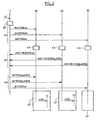
- the operations mentioned e.g. shown in the flowchart of Figure 2 or 3 , may be implemented as program modules or functional processes including routines, programs, objects, components, data structures, etc., that perform particular tasks or implement particular abstract data types and may be executed using existing hardware at existing network elements or control nodes.
- Such existing hardware may include one or more Central Processing Units (CPUs), digital signal processors (DSPs), application-specific-integrated-circuits, field programmable gate arrays (FPGAs) computers or the like.
- CPUs Central Processing Units
- DSPs digital signal processors
- FPGAs field programmable gate arrays
- the service agent 2 receives a request for establishing an inter-carrier connection, e.g. from an end-customer.
- the request specifies characteristic features of the connection to be established, including source end-point or end-points, destination end-point or end-points and traffic-engineering requirements, if any e.g. bandwidth, delay, transmission protocol or other.
- the service agent 2 retrieves service elements from data repository 3 and selects service elements adapted to fulfill the request. More precisely, service agent 2 composes a chain of adjacent service elements in view of the edges indicated in the service elements and knowledge of inter-carrier interfaces between the resource domains. If the request specifies further traffic-engineering requirements, SLA-related parameters specified in the service elements are taken into account in the composition step to prune service elements that may not meet the specified traffic-engineering requirements.
- the composition step 42 is assumed to yield a chain of service elements that already specifies the ICIs which will be used by the connection. Namely, service elements with edges specified at ICI level have been selected, or service elements with edges specified at border node level have been selected and the service agent 2 knows the inter-carrier interfaces that connect the border nodes.
- service agent 2 takes into account the existence of ICIs i1 and i4 to determine that the selected service elements are actually adjacent.
- service agent 2 also allocates an identifier SID to the connection request. This identifier can then be used in all transactions related to the request.
- service agent sends an instantiation request INST to all service providers involved in the selected chain of service elements.
- the instantiation request INST comprises the identifier SID and an identifier of the respective service element to be instantiated by the service provider system, namely a, b and c in the illustrated example.
- a service provider system instantiates the identified service element. Namely, the service provider system determines a specific intra-domain connection path that embodies the connectivity attributes specified in the service element between the edges specified in the service element.
- the connection paths selected at step 44 represent respective segments of the end-to-end connection that will be finally established when the process completes successfully.
- diverse modules of the service provider system may be involved, e.g. path computation elements or routers.
- service provider system 15 selects a path through nodes 13, 16 and 11; service provider system 25 selects a path through nodes 21, 26 and 23;and service provider system 35 selects a path through nodes 31 and 33.
- each service provider system or at least one of the provider systems receiving an instantiation request selects and reserves a communication resource at an ICI located at an end of the selected connection path, e.g. at the ingress end.
- service provider system 35 reserves resources identified by an identifier ICR3 at ingress ICI i4 and service provider system 25 reserves resources identified by an identifier ICR2 at ingress ICI i1.
- each service provider system sends an instantiation response INST-RES to the service agent 2 to indicate that the instantiation of the respective service element has completed successfully.
- an identifier of the communication resources is also included in the instantiation response.
- system 25 transmits an instantiation response comprising identifier ICR2 and system 35 transmits an instantiation response comprising identifier ICR3.
- a service provider system could not instantiate a service element at step 44, e.g. due to lack of resources, then the instantiation response INST-RES would indicate this, e.g. by means of a specific object or field or message type. Then the process could crank back to step 42 to try a different chain of service elements.
- service agent 2 upon receiving the instantiation responses INST-RES, service agent 2 sends an activation request ACT to each of the service providers involved in the chain to have the service providers activate the selected connection segments.
- service agent 2 forwards each inter-carrier communication resource identifier received at step 45 to the corresponding neighbour service provider system to have the service providers concatenate the respective connection segments using the identified communication resources.
- An inter-carrier communication resource identifier may be forwarded within the activation request or in a separate message.
- each service provider system receiving an activation request configures the nodes along the path to establish the connection segment within the associated resource domain. This may be accomplished using diverse techniques, e.g. distributed processes such as RSVP-TE signalling or centralized processes such as node configuration by a central network management device.
- Each service provider system also forwards the inter-carrier communication resource identifier received at step 46, if any, to a corresponding edge node of the resource domain, for the edge node to concatenate the intra-domain connection segment with the subsequent connection segment established in the neighbour resource domain.
- service agent 2 forwards identifier ICR2 to service provider system 15 at step 46 and service provider system 15 forwards identifier ICR2 to edge node 11 at step 47, for edge node 11 to concatenate the connection segment with the identified resources on ICI i1.
- the inter-carrier communication resources identified by identifier ICR2 have been reserved for edge node 21 to receive traffic.
- edge node 21 is already prepared to receive traffic using the reserved resources.
- edge node 11 gets prepared to send traffic using the reserved resources.
- concatenation of the respective connection segments can be achieved without exchanging further signalling messages between edge nodes 11 and 21.
- a similar result is obtained between edge nodes 23 and 31.
- the resulting end-to-end inter-carrier connection 100 is fully established when step 47 is completed.
- the communication resources at the ICI may encompass various types of resources, depending on the physical layer or layers implemented at the inter-carrier interface.
- a communication resource can include a physical port or a physical medium connected to a port, such as an optical fibre, a waveguide, a coaxial cable, or an electrical cable or wire.
- a communication resource can include an electromagnetic link, such as a radio link or a microwave link, or a frequency channel or a set of frequency channels on an electromagnetic link.
- a communication resource can include an optical link, in any part of the spectrum, e.g. visible, infrared or ultraviolet, or a wavelength channel or a set of wavelength channels on an optical link.
- a communication resource can include a timeslot or a set of timeslots on a TDM link, such as an optical link or a radio link or other electromagnetic links.
- a communication resource can include a channel code of a Code Division Multiple Access link.
- Various types of information may serve to identify a communication resource, depending on the type of the resource to be identified. The information in the instantiation response should identify the communication resource at the inter-carrier interface in a way that enables the neighbour service provider to concatenate the connection segments through the identified communication resource.
- the communication resource identifier can be selected from a group comprising an MPLS or GMPLS Label, a physical link identifier, e.g.
- a channel identifier e.g. for identifying a electromagnetic channel, a radio frequency channel, an optical wavelength channel or other, and a channel identifier identifying a channel or set of channels in a multiplex, e.g. a timeslot in a TDM signal or a wavelength in a WDM signal.
- concatenating the respective connection segments may involve various operations at the edge nodes, including configuring an MPLS forwarding table, configuring an electronic or optical switch matrix and others.
- service provider systems operate during an instantiation step to reserve a communication resource at an ICI located at an ingress interface of the associated resource domain.
- service provider systems operate to reserve a communication resource at an ICI located at an egress interface of the associated resource domain.
- a service provider system instantiating a transit service element may reserve communication resources at ICIs located at both ends of the connection path across the associated resource domain.
- inter-carrier communication resources identifiers carried in messages INST-RES and ACT are implicitly referring to those edge nodes.
- those messages may explicitly specify an edge node to which an inter-carrier communication resource identifier relates.
- service provider system 25 sends an instantiation response comprising both identifier ICR2 and an identifier for edge node 21, e.g. an IP address.
- Explicit identification of the edge nodes in the service layer messages is even more useful in embodiments in which the edge nodes of the connection path are not specified in the service elements selected at step 42. This situation will be illustrated with reference to Figure 3 .
- composition step 42 is assumed to yield a chain of service elements that does not specify the ICIs which will be used by the connection. Namely, service elements with edges specified at domain level have been selected. To illustrate such a situation, the following example is proposed:
- the instantiation step in each resource domain is performed sequentially, e.g. from egress to ingress as illustrated or the other way around, to ensure the existence of ICIs interconnecting the respective connection segments.
- service provider system 35 selects a connection path that interfaces with the specified edge of the service element f i.e. domain 20. For example, service provider system 35 selects a connection path that ends at ingress ICI i4.
- service provider system 35 sends an instantiation response that specifies both the selected ingress ICI, namely i4 and the selected resource identifier on the ingress ICI, namely ICR3.
- service agent 2 sends provider system 25 an instantiation request that specifies the ICI i4 selected by the previous service provider in the chain.
- service provider system 25 selects a connection path under the constraint that the path will actually end at egress interface i1.
- service provider system 25 sends an instantiation response that specifies both the selected ingress ICI, namely i1 and the selected resource identifier on the ingress ICI, namely ICR2.
- service agent 2 sends provider system 15 an instantiation request that specifies the ICI i1 selected by the previous service provider in the chain.
- service provider system 15 selects a connection path under the constraint that the path will actually end at egress interface i 1.
- the instantiation step and activation step may be merged, e.g. for the sake of minimizing the number of messages exchanged between the service agent 2 and the service provider systems 15, 25 and 35.
- each service provider performs step 47 immediately after step 44, without waiting for an activation message from service agent 2.
- service agent 2 already includes the respective inter-carrier communication resource identifiers ICR2 and ICR3 in the instantiation requests sent at step 43 to service provider systems 25 and 15 respectively.
- a service provider in order to facilitate and/or speed up the step of instantiating a service element at step 44, can use a data repository in which a set of pre-computed connection paths embodying the respective service elements published by that service provider have been previously stored. Therefore, at step 44, the service provider system only needs to retrieve a pre-computed connection path matching the desired service element number.
- the pre-computation and storage of connection paths by a service provider is described in closer details in pending patent application FR2008055453 filed on 6 August 2008 .
- a connection segment in a resource domain is established as an MPLS or GMPLS Label Switched Path (LSP).
- LSP stitching can be used to concatenate multiple LSPs.
- the edge node of a resource domain uses the inter-carrier communication resource identifier at step 47 to perform LSP stitching operations, so as to concatenate two adjacent LSPs.
- the inter-carrier communication resource identifier comprises an MPLS or GMPLS label. Service providers may define in advance a set of labels that may be used on an ICI for inter-carrier connections so as to improve resource management. Then, at step 44, the inter-carrier communication resource identifier can be chosen within the predefined set.
- connection segment establishment may rely on intra-domain RSVP-TE signalling or other techniques, e.g. configuration by a domain-level network management device.
Claims (14)
- Verfahren zum Aufbau einer verkehrstechnischen Verbindung durch Ressourcendomänen, die mehreren Dienstanbietern gehören, für den Datentransport, wobei eine jede der Ressourcendomänen (10, 20, 30) einem der assoziierten Dienstanbieter gehört, wobei das Verfahren umfasst:Bestimmen (41), durch einen Dienstagenten (2), von Quell- und Zielendpunkten für die Verbindung,Empfangen, am Dienstagenten, eines Dienstelements von einem jeden der Dienstanbieter, wobei das Dienstelement Ränder einer dem assoziierten Dienstprovider gehörenden Ressourcendomäne sowie Konnektivitätsattribute, welche die vom Dienstanbieter zwischen den besagten Rändern bereitgestellte Konnektivität spezifizieren, identifiziert,Bestimmen (42), durch den Dienstagenten, einer Kette von benachbarten Dienstelementen, welche fähig ist, die Quell- und Zielendpunkte auf der Basis der identifizierten Ränder miteinander zu verbinden,Auffordern (43), durch den Dienstagenten, eines ersten mit einem Dienstelement in der Kette assoziierten Dienstanbieters (35), ein erstes Verbindungssegment, welches das Dienstelement einschließt, auszuwählen (44),Empfangen (45), am Dienstagenten, einer Zwischenträger-Kommunikationsressourcenkennung (ICR3) von dem ersten Dienstanbieter, wobei die besagte Zwischenträger-Kommunikationsressourcenkennung Kommunikationsressourcen an einer Zwischenträger-Schnittstelle zwischen einem Endpunkt des ersten Verbindungssegments und einer Ressourcendomäne, welche einem zweiten Dienstanbieter (25) gehört und mit einem benachbarten Dienstelement in der Kette assoziiert ist, angibt, wobei die Zwischenträger-Schnittstelle eine direkte physikalische Schnittstelle zwischen einem ersten Netzwerkelement, welches dem ersten Dienstanbieter gehört und von diesem betrieben wird, und einem zweiten Netzwerkelement, welches dem zweiten Dienstanbieter (25) gehört und von diesem betrieben wird, ist,Übertragen (46, 43), durch den Dienstagenten, der Zwischenträger-Kommunikationsressourcenkennung an den mit dem benachbarten Dienstelement assoziierten zweiten Dienstanbieter (25).
- Verfahren nach Anspruch 1, wobei die Zwischenträger-Kommunikationsressourcenkennung innerhalb einer Bestätigungsnachricht (INST-RES), welche eine Verfügbarkeit des ersten Verbindungssegments angibt, an den Dienstagenten (2) gesendet wird.
- Verfahren nach einem beliebigen der Ansprüche 1 und 2, wobei die Zwischenträger-Kommunikationsressourcenkennung von dem Dienstagenten innerhalb einer Aktivierungsanforderung (ACT, INST), in welcher der zweite Dienstanbieter aufgefordert wird, ein zweites Verbindungssegment, welches das benachbarte Dienstelement einschließt, aufzubauen, übertragen wird.
- Verfahren nach einem beliebigen der Ansprüche 1 bis 3, wobei die Ränder des Dienstelements als Grenzknoten identifiziert werden, wobei der Dienstagent die Kette von benachbarten Dienstelementen in Abhängigkeit von Grenzknotennachbarschaften bestimmt.
- Verfahren nach einem beliebigen der Ansprüche 1 bis 4, wobei der Dienstagent parallel den mit einem Dienstelement in der Kette assoziierten ersten Dienstanbieter und den mit einem benachbarten Dienstelement assoziierten zweiten Dienstanbieter auffordert, entsprechende Verbindungssegmente zwischen den in den jeweiligen Dienstelementen identifizierten Grenzknoten auszuwählen.
- Verfahren nach einem beliebigen der Ansprüche 1 bis 3, wobei die Ränder des Dienstelements als Nachbarressourcendomänen identifiziert werden.
- Verfahren nach Anspruch 6, wobei der Dienstagent die Zwischenträger-Kommunikationsressourcenkennung (i4, ICR3) innerhalb einer Anforderung (INST) für die Auswahl eines zweiten Verbindungssegments, welches das benachbarte Dienstelement in der Kette einschließt, an den zweiten Dienstanbieter (25) überträgt (43), wobei der zweite Dienstanbieter das zweite Verbindungssegment in Abhängigkeit von der Zwischenträger-Kommunikationsressourcenkennung derart auswählt, dass das zweite Verbindungssegment an der durch die Zwischenträger-Kommunikationsressourcenkennung angegebene Zwischenträger-Schnittstelle (i4) endet.
- Verfahren nach einem beliebigen der Ansprüche 1 bis 7, wobei der erste Dienstanbieter das erste Verbindungssegment aus einem Satz von vorausberechneten Verbindungssegmenten, welche das Dienstelement einschließen, auswählt.
- Verfahren nach einem beliebigen der Ansprüche 1 bis 8, wobei die Zwischenträger-Kommunikationsressourcenkennung ein MPLS-Label oder ein GMPLS-Label umfasst.
- Verfahren nach einem beliebigen der Ansprüche 1 bis 9, wobei der Dienstagent gewünschte Leistungsparameter für die Verbindung bestimmt und die Kette von Dienstelementen in Abhängigkeit von den Konnektivitätsattributen der Dienstelemente derart bestimmt, dass sie den gewünschten Leistungsparametern entsprechen.
- Verfahren nach einem beliebigen der Ansprüche 1 bis 10, wobei der Dienstagent eine Dienstkennung (SID) für die Verbindung bestimmt und die Dienstkennung an die mit den Dienstelementen in der Kette assoziierten Dienstanbieter übermittelt, und die Dienstanbieter die Kennung denjenigen Verbindungssegmenten zuweisen, welche die Dienstelemente einschließen.
- Dienstagent (2) zum Aufbau einer verkehrstechnischen Verbindung durch Ressourcendomänen für den Datentransport, wobei eine jede der Ressourcendomänen einem assoziierten Dienstanbieter gehört, wobei der Dienstagent ein Verarbeitungsmodul für das Durchführen der folgenden Schritte umfasst:Bestimmen (41) von Quell- und Zielendpunkten für die Verbindung,Empfangen eines Dienstelements von einem jeden der Dienstanbieter, wobei das Dienstelement Ränder einer dem assoziierten Dienstprovider gehörenden Ressourcendomäne sowie Konnektivitätsattribute, welche die vom Dienstanbieter zwischen den besagten Rändern bereitgestellte Konnektivität spezifizieren, identifiziert,Bestimmen (42) einer Kette von benachbarten Dienstelementen, welche fähig ist, die Quell- und Zielendpunkte auf der Basis der identifizierten Ränder miteinander zu verbinden,Auffordern (43) eines ersten mit einem Dienstelement in der Kette assoziierten Dienstanbieters, ein erstes Verbindungssegment, welches das Dienstelement einschließt, auszuwählen,Empfangen (45) einer Zwischenträger-Kommunikationsressourcenkennung von dem ersten Dienstanbieter, wobei die besagte Zwischenträger-Kommunikationsressourcenkennung Kommunikationsressourcen an einer Zwischenträger-Schnittstelle zwischen dem ersten Verbindungssegment und einer Ressourcendomäne, welche einem zweiten Dienstanbieter (25) gehört und mit einem benachbarten Dienstelement in der Kette assoziiert ist, angibt, wobei die Zwischenträger-Schnittstelle eine direkte physikalische Schnittstelle zwischen einem ersten Netzwerkelement, welches dem ersten Dienstanbieter gehört und von diesem betrieben wird, und einem zweiten Netzwerkelement, welches dem zweiten Dienstanbieter (25) gehört und von diesem betrieben wird, ist,Übertragen (43, 46) der Zwischenträger-Kommunikationsressourcenkennung an den mit dem benachbarten Dienstelement assoziierten zweiten Dienstanbieter.
- Dienstanbietersystem (15) für einen ersten Dienstanbieter, dem eine Ressourcendomäne gehört und der einem Zusammenschluss von Dienstanbietern angehört, zum Aufbau von domänenübergreifenden Verbindungen durch die Ressourcendomäne, wobei das Dienstanbietersystem umfasst:Eine Schnittstelle für die Kommunikation mit einem Dienstagenten (2),ein Steuermodul, welches dazu ausgelegt ist, eine Instanziierungsanforderung (INST) mit einer Dienstelementkennung und einer Dienstkennung zu erkennen, ein Verbindungssegment, welches das Dienstelement innerhalb einer Ressourcendomäne einschließt, auszuwählen (44), eine Zwischenträger-Schnittstelle an einem Endpunkt des Verbindungssegments auszuwählen, eine Kommunikationsressource an der Zwischenträger-Schnittstelle zu reservieren und eine Zwischenträger-Kommunikationsressourcenkennung, welche in Reaktion auf die Instanziierungsanforderung die Kommunikationsressourcen an den Dienstagenten angibt,zu übermitteln (45), wobei die Zwischenträger-Schnittstelle eine direkte physikalische Schnittstelle zwischen einem ersten Netzwerkelement, welches dem ersten Dienstanbieter gehört und von diesem betrieben wird, und einem zweiten Netzwerkelement, welches dem zweiten Dienstanbieter (25) des Dienstanbieter-Zusammenschlusses gehört und von diesem betrieben wird, ist.
- Dienstanbietersystem (25) für einen zweiten Dienstanbieter, dem eine Ressourcendomäne gehört und der einem Zusammenschluss von Dienstanbietern angehört, für den Aufbau von domänenübergreifenden Verbindungen durch die Ressourcendomäne, wobei das Dienstanbietersystem umfasst:Eine Schnittstelle für die Kommunikation mit einem Dienstagenten (2),ein Steuermodul, welches dazu ausgelegt ist, eine Aktivierungsanforderung (ACT, INST) mit einer Zwischenträger-Kommunikationsressourcenkennung (ICR3) und einer Dienstkennung (SID) zu erkennen, ein mit der Dienstkennung assoziiertes Verbindungssegment zu bestimmen (44), wobei sich das Verbindungssegment innerhalb der Ressourcendomäne befindet, und das Verbindungssegment mit einer Kommunikationsressource an einer von der Zwischenträger-Kommunikationsressourcenkennung angegebenen Zwischenträger-Schnittstelle zu verketten (47), wobei die Zwischenträger-Schnittstelle eine direkte physikalische Schnittstelle zwischen einem ersten Netzwerkelement, welches dem ersten Dienstanbieter (35) gehört und von diesem betrieben wird, und einem zweiten Netzwerkelement, welches dem zweiten Dienstanbieter (25) gehört und von diesem betrieben wird, ist.
Priority Applications (6)
| Application Number | Priority Date | Filing Date | Title |
|---|---|---|---|
| EP20090305402 EP2249525B1 (de) | 2009-05-06 | 2009-05-06 | Aufbau einer Traffic-Engineered-Verbindung über Ressourcendomains zum Datentransport |
| KR1020117026208A KR101333020B1 (ko) | 2009-05-06 | 2010-03-15 | 데이터 전송을 위한 리소스 도메인들에 걸친 트래픽―엔지니어드 접속 확립 |
| US13/265,963 US8750287B2 (en) | 2009-05-06 | 2010-03-15 | Traffic-engineered connection establishment across resource domains for data transport |
| CN201080019935.4A CN102422602B (zh) | 2009-05-06 | 2010-03-15 | 用于数据传输的跨越资源域的流量工程连接建立 |
| PCT/EP2010/053244 WO2010127893A1 (en) | 2009-05-06 | 2010-03-15 | Traffic-engineered connection establishment across resource domains for data transport |
| JP2012508961A JP2012526433A (ja) | 2009-05-06 | 2010-03-15 | データトランスポートのためのリソースドメインをわたるトラフィックエンジニアリングされた接続の確立 |
Applications Claiming Priority (1)
| Application Number | Priority Date | Filing Date | Title |
|---|---|---|---|
| EP20090305402 EP2249525B1 (de) | 2009-05-06 | 2009-05-06 | Aufbau einer Traffic-Engineered-Verbindung über Ressourcendomains zum Datentransport |
Publications (2)
| Publication Number | Publication Date |
|---|---|
| EP2249525A1 EP2249525A1 (de) | 2010-11-10 |
| EP2249525B1 true EP2249525B1 (de) | 2012-10-31 |
Family
ID=40933611
Family Applications (1)
| Application Number | Title | Priority Date | Filing Date |
|---|---|---|---|
| EP20090305402 Not-in-force EP2249525B1 (de) | 2009-05-06 | 2009-05-06 | Aufbau einer Traffic-Engineered-Verbindung über Ressourcendomains zum Datentransport |
Country Status (6)
| Country | Link |
|---|---|
| US (1) | US8750287B2 (de) |
| EP (1) | EP2249525B1 (de) |
| JP (1) | JP2012526433A (de) |
| KR (1) | KR101333020B1 (de) |
| CN (1) | CN102422602B (de) |
| WO (1) | WO2010127893A1 (de) |
Families Citing this family (35)
| Publication number | Priority date | Publication date | Assignee | Title |
|---|---|---|---|---|
| US9729424B2 (en) * | 2012-06-11 | 2017-08-08 | Futurewei Technologies, Inc. | Defining data flow paths in software-defined networks with application-layer traffic optimization |
| CN103533463A (zh) * | 2012-07-06 | 2014-01-22 | 中兴通讯股份有限公司 | 一种建立频谱时序通道的方法及装置 |
| US9882713B1 (en) | 2013-01-30 | 2018-01-30 | vIPtela Inc. | Method and system for key generation, distribution and management |
| US9826025B2 (en) | 2013-05-21 | 2017-11-21 | Cisco Technology, Inc. | Chaining service zones by way of route re-origination |
| US9509614B2 (en) | 2013-06-20 | 2016-11-29 | Cisco Technology, Inc. | Hierarchical load balancing in a network environment |
| US9467478B1 (en) | 2013-12-18 | 2016-10-11 | vIPtela Inc. | Overlay management protocol for secure routing based on an overlay network |
| US20160006614A1 (en) * | 2014-07-03 | 2016-01-07 | Futurewei Technologies, Inc. | Source Routing Using Path Computation Elements |
| WO2016012043A1 (en) * | 2014-07-24 | 2016-01-28 | Telefonaktiebolaget L M Ericsson (Publ) | Segment routing in a multi-domain network |
| US10374904B2 (en) | 2015-05-15 | 2019-08-06 | Cisco Technology, Inc. | Diagnostic network visualization |
| US10536357B2 (en) | 2015-06-05 | 2020-01-14 | Cisco Technology, Inc. | Late data detection in data center |
| US10142353B2 (en) | 2015-06-05 | 2018-11-27 | Cisco Technology, Inc. | System for monitoring and managing datacenters |
| US9967158B2 (en) | 2015-06-05 | 2018-05-08 | Cisco Technology, Inc. | Interactive hierarchical network chord diagram for application dependency mapping |
| US10594580B2 (en) * | 2015-08-03 | 2020-03-17 | Avago Technologies International Sales Pte. Limited | Network function virtualization management system |
| US9980303B2 (en) | 2015-12-18 | 2018-05-22 | Cisco Technology, Inc. | Establishing a private network using multi-uplink capable network devices |
| US10289438B2 (en) | 2016-06-16 | 2019-05-14 | Cisco Technology, Inc. | Techniques for coordination of application components deployed on distributed virtual machines |
| US10708183B2 (en) | 2016-07-21 | 2020-07-07 | Cisco Technology, Inc. | System and method of providing segment routing as a service |
| US10972388B2 (en) | 2016-11-22 | 2021-04-06 | Cisco Technology, Inc. | Federated microburst detection |
| US10708152B2 (en) | 2017-03-23 | 2020-07-07 | Cisco Technology, Inc. | Predicting application and network performance |
| US10523512B2 (en) | 2017-03-24 | 2019-12-31 | Cisco Technology, Inc. | Network agent for generating platform specific network policies |
| US10594560B2 (en) | 2017-03-27 | 2020-03-17 | Cisco Technology, Inc. | Intent driven network policy platform |
| US10250446B2 (en) | 2017-03-27 | 2019-04-02 | Cisco Technology, Inc. | Distributed policy store |
| US10764141B2 (en) | 2017-03-27 | 2020-09-01 | Cisco Technology, Inc. | Network agent for reporting to a network policy system |
| US10873794B2 (en) | 2017-03-28 | 2020-12-22 | Cisco Technology, Inc. | Flowlet resolution for application performance monitoring and management |
| US10680887B2 (en) | 2017-07-21 | 2020-06-09 | Cisco Technology, Inc. | Remote device status audit and recovery |
| US10554501B2 (en) | 2017-10-23 | 2020-02-04 | Cisco Technology, Inc. | Network migration assistant |
| US10523541B2 (en) | 2017-10-25 | 2019-12-31 | Cisco Technology, Inc. | Federated network and application data analytics platform |
| US10594542B2 (en) | 2017-10-27 | 2020-03-17 | Cisco Technology, Inc. | System and method for network root cause analysis |
| US11233821B2 (en) | 2018-01-04 | 2022-01-25 | Cisco Technology, Inc. | Network intrusion counter-intelligence |
| US10826803B2 (en) | 2018-01-25 | 2020-11-03 | Cisco Technology, Inc. | Mechanism for facilitating efficient policy updates |
| US10574575B2 (en) | 2018-01-25 | 2020-02-25 | Cisco Technology, Inc. | Network flow stitching using middle box flow stitching |
| US10798015B2 (en) | 2018-01-25 | 2020-10-06 | Cisco Technology, Inc. | Discovery of middleboxes using traffic flow stitching |
| US10999149B2 (en) | 2018-01-25 | 2021-05-04 | Cisco Technology, Inc. | Automatic configuration discovery based on traffic flow data |
| US11128700B2 (en) | 2018-01-26 | 2021-09-21 | Cisco Technology, Inc. | Load balancing configuration based on traffic flow telemetry |
| AT522844B1 (de) * | 2019-07-24 | 2021-05-15 | Frequentis Ag | Verfahren zur Übertragung von Daten zwischen einem Fahrzeug und einem Verkehrssicherungssystem |
| US11444871B1 (en) | 2021-07-26 | 2022-09-13 | Cisco Technology, Inc. | End-to-end path selection using dynamic software-defined cloud interconnect (SDCI) tunnels |
Citations (1)
| Publication number | Priority date | Publication date | Assignee | Title |
|---|---|---|---|---|
| EP1089517A2 (de) * | 1999-10-01 | 2001-04-04 | Nortel Networks Limited | Aufbau von Verbindungen über ein Kommunikationsnetzwerk |
Family Cites Families (9)
| Publication number | Priority date | Publication date | Assignee | Title |
|---|---|---|---|---|
| JP3617406B2 (ja) * | 2000-03-30 | 2005-02-02 | 日本電気株式会社 | マルチドメインに対応した品質保証型通信サービス提供方式およびサービス提供方法並びにサービス仲介装置 |
| US20020156914A1 (en) * | 2000-05-31 | 2002-10-24 | Lo Waichi C. | Controller for managing bandwidth in a communications network |
| JP3844724B2 (ja) * | 2002-08-21 | 2006-11-15 | 日本電信電話株式会社 | 広域ネットワークシステム及び広域ネットワーク通信方法 |
| CN100384172C (zh) * | 2004-01-20 | 2008-04-23 | 华为技术有限公司 | 基于网络的虚拟专用网中保证服务质量的系统及其方法 |
| EP1599000A1 (de) * | 2004-05-20 | 2005-11-23 | Alcatel | Bereitstellung von cross-domain Telekommunikationsdiensten mittels dynamischer Differenzierung der Label |
| CN100512209C (zh) * | 2005-05-24 | 2009-07-08 | 华为技术有限公司 | 分布式路径计算中解决资源冲突的方法 |
| JP4807701B2 (ja) * | 2006-02-28 | 2011-11-02 | 国立大学法人 名古屋工業大学 | 移動端末装置、制御方法及び移動通信システム |
| CN100454841C (zh) * | 2006-06-02 | 2009-01-21 | 华为技术有限公司 | 一种多域路由计算方法和系统 |
| US8374092B2 (en) * | 2006-08-28 | 2013-02-12 | Cisco Technology, Inc. | Technique for protecting against failure of a network element using multi-topology repair routing (MTRR) |
-
2009
- 2009-05-06 EP EP20090305402 patent/EP2249525B1/de not_active Not-in-force
-
2010
- 2010-03-15 US US13/265,963 patent/US8750287B2/en not_active Expired - Fee Related
- 2010-03-15 JP JP2012508961A patent/JP2012526433A/ja active Pending
- 2010-03-15 WO PCT/EP2010/053244 patent/WO2010127893A1/en active Application Filing
- 2010-03-15 CN CN201080019935.4A patent/CN102422602B/zh not_active Expired - Fee Related
- 2010-03-15 KR KR1020117026208A patent/KR101333020B1/ko not_active IP Right Cessation
Patent Citations (1)
| Publication number | Priority date | Publication date | Assignee | Title |
|---|---|---|---|---|
| EP1089517A2 (de) * | 1999-10-01 | 2001-04-04 | Nortel Networks Limited | Aufbau von Verbindungen über ein Kommunikationsnetzwerk |
Also Published As
| Publication number | Publication date |
|---|---|
| JP2012526433A (ja) | 2012-10-25 |
| KR101333020B1 (ko) | 2013-12-19 |
| CN102422602B (zh) | 2016-05-11 |
| US8750287B2 (en) | 2014-06-10 |
| CN102422602A (zh) | 2012-04-18 |
| WO2010127893A1 (en) | 2010-11-11 |
| KR20120005014A (ko) | 2012-01-13 |
| EP2249525A1 (de) | 2010-11-10 |
| US20120051221A1 (en) | 2012-03-01 |
Similar Documents
| Publication | Publication Date | Title |
|---|---|---|
| EP2249525B1 (de) | Aufbau einer Traffic-Engineered-Verbindung über Ressourcendomains zum Datentransport | |
| CN104426766B (zh) | 跨多个网络层的动态端到端网络路径建立 | |
| CN107637031B (zh) | 用于网络业务的路径计算单元中央控制器 | |
| CN102571557B (zh) | 动态产生应用层流量优化协议图 | |
| CN101471853B (zh) | 一种路由计算方法、单元及系统 | |
| US9491086B2 (en) | Distributed network planning systems and methods | |
| CN104780099A (zh) | 利用网络服务链化的跨多个网络层的动态端到端网络路径设立 | |
| US20140376371A1 (en) | Method and Device for Conveying Data Across at Least Two Domains | |
| CN103873366A (zh) | 具有集中控制的聚合网络 | |
| Kalmykov et al. | Segment routing as a basis for software defined network | |
| US11695688B2 (en) | Computing segment identifier lists for multipaths in a segment routing-enabled network | |
| WO2015144257A1 (en) | A method to provide elasticity in transport network virtualisation | |
| CN111245644A (zh) | 一种sdn场景下扩展pcep协议自动创建隧道的方法及系统 | |
| CN114363249B (zh) | 针对多路径分段路由的带宽约束 | |
| CN110620726A (zh) | 通信系统、通信方法及网络装置 | |
| CN103688510A (zh) | 跨网通信方法及装置 | |
| US20140185607A1 (en) | Communication system, communication path establishing method and management server | |
| US11575572B2 (en) | Network controller horizontal scaling for network device configuration sessions management | |
| CN104348744A (zh) | 一种路径计算方法及路径计算单元 | |
| CN115865769A (zh) | 报文处理方法、网络设备及系统 | |
| JP2022533224A (ja) | ネットワーク制御方法、装置、およびシステム | |
| EP4075751A1 (de) | Netzwerksteuerung mit horizontaler skalierung zur netzwerkvorrichtungskonfigurationssitzungsverwaltung | |
| CN101945033A (zh) | 一种流量工程域合并/分割时的处理方法、装置及系统 |
Legal Events
| Date | Code | Title | Description |
|---|---|---|---|
| PUAI | Public reference made under article 153(3) epc to a published international application that has entered the european phase |
Free format text: ORIGINAL CODE: 0009012 |
|
| AK | Designated contracting states |
Kind code of ref document: A1 Designated state(s): AT BE BG CH CY CZ DE DK EE ES FI FR GB GR HR HU IE IS IT LI LT LU LV MC MK MT NL NO PL PT RO SE SI SK TR |
|
| 17P | Request for examination filed |
Effective date: 20110510 |
|
| 17Q | First examination report despatched |
Effective date: 20110608 |
|
| RAP1 | Party data changed (applicant data changed or rights of an application transferred) |
Owner name: ALCATEL LUCENT |
|
| GRAP | Despatch of communication of intention to grant a patent |
Free format text: ORIGINAL CODE: EPIDOSNIGR1 |
|
| RIN1 | Information on inventor provided before grant (corrected) |
Inventor name: POUYLLAU, HELIA Inventor name: BUI, DINH THAI |
|
| GRAS | Grant fee paid |
Free format text: ORIGINAL CODE: EPIDOSNIGR3 |
|
| GRAA | (expected) grant |
Free format text: ORIGINAL CODE: 0009210 |
|
| AK | Designated contracting states |
Kind code of ref document: B1 Designated state(s): AT BE BG CH CY CZ DE DK EE ES FI FR GB GR HR HU IE IS IT LI LT LU LV MC MK MT NL NO PL PT RO SE SI SK TR |
|
| REG | Reference to a national code |
Ref country code: GB Ref legal event code: FG4D Ref country code: CH Ref legal event code: EP |
|
| REG | Reference to a national code |
Ref country code: AT Ref legal event code: REF Ref document number: 582511 Country of ref document: AT Kind code of ref document: T Effective date: 20121115 |
|
| REG | Reference to a national code |
Ref country code: IE Ref legal event code: FG4D |
|
| REG | Reference to a national code |
Ref country code: DE Ref legal event code: R096 Ref document number: 602009010801 Country of ref document: DE Effective date: 20121227 |
|
| REG | Reference to a national code |
Ref country code: AT Ref legal event code: MK05 Ref document number: 582511 Country of ref document: AT Kind code of ref document: T Effective date: 20121031 |
|
| REG | Reference to a national code |
Ref country code: LT Ref legal event code: MG4D |
|
| REG | Reference to a national code |
Ref country code: NL Ref legal event code: VDEP Effective date: 20121031 |
|
| PG25 | Lapsed in a contracting state [announced via postgrant information from national office to epo] |
Ref country code: NL Free format text: LAPSE BECAUSE OF FAILURE TO SUBMIT A TRANSLATION OF THE DESCRIPTION OR TO PAY THE FEE WITHIN THE PRESCRIBED TIME-LIMIT Effective date: 20121031 Ref country code: LT Free format text: LAPSE BECAUSE OF FAILURE TO SUBMIT A TRANSLATION OF THE DESCRIPTION OR TO PAY THE FEE WITHIN THE PRESCRIBED TIME-LIMIT Effective date: 20121031 Ref country code: SE Free format text: LAPSE BECAUSE OF FAILURE TO SUBMIT A TRANSLATION OF THE DESCRIPTION OR TO PAY THE FEE WITHIN THE PRESCRIBED TIME-LIMIT Effective date: 20121031 Ref country code: NO Free format text: LAPSE BECAUSE OF FAILURE TO SUBMIT A TRANSLATION OF THE DESCRIPTION OR TO PAY THE FEE WITHIN THE PRESCRIBED TIME-LIMIT Effective date: 20130131 Ref country code: HR Free format text: LAPSE BECAUSE OF FAILURE TO SUBMIT A TRANSLATION OF THE DESCRIPTION OR TO PAY THE FEE WITHIN THE PRESCRIBED TIME-LIMIT Effective date: 20121031 Ref country code: FI Free format text: LAPSE BECAUSE OF FAILURE TO SUBMIT A TRANSLATION OF THE DESCRIPTION OR TO PAY THE FEE WITHIN THE PRESCRIBED TIME-LIMIT Effective date: 20121031 Ref country code: IS Free format text: LAPSE BECAUSE OF FAILURE TO SUBMIT A TRANSLATION OF THE DESCRIPTION OR TO PAY THE FEE WITHIN THE PRESCRIBED TIME-LIMIT Effective date: 20130228 Ref country code: ES Free format text: LAPSE BECAUSE OF FAILURE TO SUBMIT A TRANSLATION OF THE DESCRIPTION OR TO PAY THE FEE WITHIN THE PRESCRIBED TIME-LIMIT Effective date: 20130211 |
|
| PG25 | Lapsed in a contracting state [announced via postgrant information from national office to epo] |
Ref country code: BE Free format text: LAPSE BECAUSE OF FAILURE TO SUBMIT A TRANSLATION OF THE DESCRIPTION OR TO PAY THE FEE WITHIN THE PRESCRIBED TIME-LIMIT Effective date: 20121031 Ref country code: PL Free format text: LAPSE BECAUSE OF FAILURE TO SUBMIT A TRANSLATION OF THE DESCRIPTION OR TO PAY THE FEE WITHIN THE PRESCRIBED TIME-LIMIT Effective date: 20121031 Ref country code: SI Free format text: LAPSE BECAUSE OF FAILURE TO SUBMIT A TRANSLATION OF THE DESCRIPTION OR TO PAY THE FEE WITHIN THE PRESCRIBED TIME-LIMIT Effective date: 20121031 Ref country code: PT Free format text: LAPSE BECAUSE OF FAILURE TO SUBMIT A TRANSLATION OF THE DESCRIPTION OR TO PAY THE FEE WITHIN THE PRESCRIBED TIME-LIMIT Effective date: 20130228 Ref country code: LV Free format text: LAPSE BECAUSE OF FAILURE TO SUBMIT A TRANSLATION OF THE DESCRIPTION OR TO PAY THE FEE WITHIN THE PRESCRIBED TIME-LIMIT Effective date: 20121031 Ref country code: GR Free format text: LAPSE BECAUSE OF FAILURE TO SUBMIT A TRANSLATION OF THE DESCRIPTION OR TO PAY THE FEE WITHIN THE PRESCRIBED TIME-LIMIT Effective date: 20130201 |
|
| PG25 | Lapsed in a contracting state [announced via postgrant information from national office to epo] |
Ref country code: AT Free format text: LAPSE BECAUSE OF FAILURE TO SUBMIT A TRANSLATION OF THE DESCRIPTION OR TO PAY THE FEE WITHIN THE PRESCRIBED TIME-LIMIT Effective date: 20121031 |
|
| PG25 | Lapsed in a contracting state [announced via postgrant information from national office to epo] |
Ref country code: BG Free format text: LAPSE BECAUSE OF FAILURE TO SUBMIT A TRANSLATION OF THE DESCRIPTION OR TO PAY THE FEE WITHIN THE PRESCRIBED TIME-LIMIT Effective date: 20130131 Ref country code: DK Free format text: LAPSE BECAUSE OF FAILURE TO SUBMIT A TRANSLATION OF THE DESCRIPTION OR TO PAY THE FEE WITHIN THE PRESCRIBED TIME-LIMIT Effective date: 20121031 Ref country code: EE Free format text: LAPSE BECAUSE OF FAILURE TO SUBMIT A TRANSLATION OF THE DESCRIPTION OR TO PAY THE FEE WITHIN THE PRESCRIBED TIME-LIMIT Effective date: 20121031 Ref country code: CZ Free format text: LAPSE BECAUSE OF FAILURE TO SUBMIT A TRANSLATION OF THE DESCRIPTION OR TO PAY THE FEE WITHIN THE PRESCRIBED TIME-LIMIT Effective date: 20121031 Ref country code: SK Free format text: LAPSE BECAUSE OF FAILURE TO SUBMIT A TRANSLATION OF THE DESCRIPTION OR TO PAY THE FEE WITHIN THE PRESCRIBED TIME-LIMIT Effective date: 20121031 |
|
| PG25 | Lapsed in a contracting state [announced via postgrant information from national office to epo] |
Ref country code: RO Free format text: LAPSE BECAUSE OF FAILURE TO SUBMIT A TRANSLATION OF THE DESCRIPTION OR TO PAY THE FEE WITHIN THE PRESCRIBED TIME-LIMIT Effective date: 20121031 Ref country code: IT Free format text: LAPSE BECAUSE OF FAILURE TO SUBMIT A TRANSLATION OF THE DESCRIPTION OR TO PAY THE FEE WITHIN THE PRESCRIBED TIME-LIMIT Effective date: 20121031 |
|
| PLBE | No opposition filed within time limit |
Free format text: ORIGINAL CODE: 0009261 |
|
| STAA | Information on the status of an ep patent application or granted ep patent |
Free format text: STATUS: NO OPPOSITION FILED WITHIN TIME LIMIT |
|
| 26N | No opposition filed |
Effective date: 20130801 |
|
| REG | Reference to a national code |
Ref country code: GB Ref legal event code: 732E Free format text: REGISTERED BETWEEN 20130926 AND 20131002 |
|
| REG | Reference to a national code |
Ref country code: FR Ref legal event code: GC Effective date: 20131018 |
|
| REG | Reference to a national code |
Ref country code: DE Ref legal event code: R097 Ref document number: 602009010801 Country of ref document: DE Effective date: 20130801 |
|
| PG25 | Lapsed in a contracting state [announced via postgrant information from national office to epo] |
Ref country code: CY Free format text: LAPSE BECAUSE OF FAILURE TO SUBMIT A TRANSLATION OF THE DESCRIPTION OR TO PAY THE FEE WITHIN THE PRESCRIBED TIME-LIMIT Effective date: 20121031 |
|
| PG25 | Lapsed in a contracting state [announced via postgrant information from national office to epo] |
Ref country code: MC Free format text: LAPSE BECAUSE OF FAILURE TO SUBMIT A TRANSLATION OF THE DESCRIPTION OR TO PAY THE FEE WITHIN THE PRESCRIBED TIME-LIMIT Effective date: 20121031 |
|
| REG | Reference to a national code |
Ref country code: CH Ref legal event code: PL |
|
| PG25 | Lapsed in a contracting state [announced via postgrant information from national office to epo] |
Ref country code: LI Free format text: LAPSE BECAUSE OF NON-PAYMENT OF DUE FEES Effective date: 20130531 Ref country code: CH Free format text: LAPSE BECAUSE OF NON-PAYMENT OF DUE FEES Effective date: 20130531 |
|
| REG | Reference to a national code |
Ref country code: IE Ref legal event code: MM4A |
|
| PG25 | Lapsed in a contracting state [announced via postgrant information from national office to epo] |
Ref country code: IE Free format text: LAPSE BECAUSE OF NON-PAYMENT OF DUE FEES Effective date: 20130506 |
|
| REG | Reference to a national code |
Ref country code: FR Ref legal event code: RG Effective date: 20141016 |
|
| PG25 | Lapsed in a contracting state [announced via postgrant information from national office to epo] |
Ref country code: MT Free format text: LAPSE BECAUSE OF FAILURE TO SUBMIT A TRANSLATION OF THE DESCRIPTION OR TO PAY THE FEE WITHIN THE PRESCRIBED TIME-LIMIT Effective date: 20121031 |
|
| REG | Reference to a national code |
Ref country code: FR Ref legal event code: PLFP Year of fee payment: 7 |
|
| PG25 | Lapsed in a contracting state [announced via postgrant information from national office to epo] |
Ref country code: TR Free format text: LAPSE BECAUSE OF FAILURE TO SUBMIT A TRANSLATION OF THE DESCRIPTION OR TO PAY THE FEE WITHIN THE PRESCRIBED TIME-LIMIT Effective date: 20121031 |
|
| PG25 | Lapsed in a contracting state [announced via postgrant information from national office to epo] |
Ref country code: HU Free format text: LAPSE BECAUSE OF FAILURE TO SUBMIT A TRANSLATION OF THE DESCRIPTION OR TO PAY THE FEE WITHIN THE PRESCRIBED TIME-LIMIT; INVALID AB INITIO Effective date: 20090506 Ref country code: LU Free format text: LAPSE BECAUSE OF NON-PAYMENT OF DUE FEES Effective date: 20130506 Ref country code: MK Free format text: LAPSE BECAUSE OF FAILURE TO SUBMIT A TRANSLATION OF THE DESCRIPTION OR TO PAY THE FEE WITHIN THE PRESCRIBED TIME-LIMIT Effective date: 20121031 |
|
| REG | Reference to a national code |
Ref country code: FR Ref legal event code: PLFP Year of fee payment: 8 |
|
| REG | Reference to a national code |
Ref country code: FR Ref legal event code: PLFP Year of fee payment: 9 |
|
| PGFP | Annual fee paid to national office [announced via postgrant information from national office to epo] |
Ref country code: DE Payment date: 20170523 Year of fee payment: 9 Ref country code: FR Payment date: 20170523 Year of fee payment: 9 Ref country code: GB Payment date: 20170519 Year of fee payment: 9 |
|
| REG | Reference to a national code |
Ref country code: DE Ref legal event code: R119 Ref document number: 602009010801 Country of ref document: DE |
|
| GBPC | Gb: european patent ceased through non-payment of renewal fee |
Effective date: 20180506 |
|
| PG25 | Lapsed in a contracting state [announced via postgrant information from national office to epo] |
Ref country code: FR Free format text: LAPSE BECAUSE OF NON-PAYMENT OF DUE FEES Effective date: 20180531 Ref country code: DE Free format text: LAPSE BECAUSE OF NON-PAYMENT OF DUE FEES Effective date: 20181201 Ref country code: GB Free format text: LAPSE BECAUSE OF NON-PAYMENT OF DUE FEES Effective date: 20180506 |