EP2249099B1 - Fluid heating device - Google Patents
Fluid heating device Download PDFInfo
- Publication number
- EP2249099B1 EP2249099B1 EP09704296.4A EP09704296A EP2249099B1 EP 2249099 B1 EP2249099 B1 EP 2249099B1 EP 09704296 A EP09704296 A EP 09704296A EP 2249099 B1 EP2249099 B1 EP 2249099B1
- Authority
- EP
- European Patent Office
- Prior art keywords
- fluid
- heating
- ceramic heater
- flow path
- heating device
- Prior art date
- Legal status (The legal status is an assumption and is not a legal conclusion. Google has not performed a legal analysis and makes no representation as to the accuracy of the status listed.)
- Not-in-force
Links
Images




Classifications
-
- F—MECHANICAL ENGINEERING; LIGHTING; HEATING; WEAPONS; BLASTING
- F24—HEATING; RANGES; VENTILATING
- F24H—FLUID HEATERS, e.g. WATER OR AIR HEATERS, HAVING HEAT-GENERATING MEANS, e.g. HEAT PUMPS, IN GENERAL
- F24H1/00—Water heaters, e.g. boilers, continuous-flow heaters or water-storage heaters
- F24H1/18—Water-storage heaters
- F24H1/20—Water-storage heaters with immersed heating elements, e.g. electric elements or furnace tubes
-
- F—MECHANICAL ENGINEERING; LIGHTING; HEATING; WEAPONS; BLASTING
- F24—HEATING; RANGES; VENTILATING
- F24H—FLUID HEATERS, e.g. WATER OR AIR HEATERS, HAVING HEAT-GENERATING MEANS, e.g. HEAT PUMPS, IN GENERAL
- F24H1/00—Water heaters, e.g. boilers, continuous-flow heaters or water-storage heaters
- F24H1/10—Continuous-flow heaters, i.e. heaters in which heat is generated only while the water is flowing, e.g. with direct contact of the water with the heating medium
- F24H1/12—Continuous-flow heaters, i.e. heaters in which heat is generated only while the water is flowing, e.g. with direct contact of the water with the heating medium in which the water is kept separate from the heating medium
- F24H1/121—Continuous-flow heaters, i.e. heaters in which heat is generated only while the water is flowing, e.g. with direct contact of the water with the heating medium in which the water is kept separate from the heating medium using electric energy supply
-
- F—MECHANICAL ENGINEERING; LIGHTING; HEATING; WEAPONS; BLASTING
- F24—HEATING; RANGES; VENTILATING
- F24H—FLUID HEATERS, e.g. WATER OR AIR HEATERS, HAVING HEAT-GENERATING MEANS, e.g. HEAT PUMPS, IN GENERAL
- F24H1/00—Water heaters, e.g. boilers, continuous-flow heaters or water-storage heaters
- F24H1/18—Water-storage heaters
-
- F—MECHANICAL ENGINEERING; LIGHTING; HEATING; WEAPONS; BLASTING
- F24—HEATING; RANGES; VENTILATING
- F24H—FLUID HEATERS, e.g. WATER OR AIR HEATERS, HAVING HEAT-GENERATING MEANS, e.g. HEAT PUMPS, IN GENERAL
- F24H1/00—Water heaters, e.g. boilers, continuous-flow heaters or water-storage heaters
- F24H1/18—Water-storage heaters
- F24H1/20—Water-storage heaters with immersed heating elements, e.g. electric elements or furnace tubes
- F24H1/201—Water-storage heaters with immersed heating elements, e.g. electric elements or furnace tubes using electric energy supply
- F24H1/202—Water-storage heaters with immersed heating elements, e.g. electric elements or furnace tubes using electric energy supply with resistances
-
- F—MECHANICAL ENGINEERING; LIGHTING; HEATING; WEAPONS; BLASTING
- F24—HEATING; RANGES; VENTILATING
- F24H—FLUID HEATERS, e.g. WATER OR AIR HEATERS, HAVING HEAT-GENERATING MEANS, e.g. HEAT PUMPS, IN GENERAL
- F24H9/00—Details
- F24H9/18—Arrangement or mounting of grates or heating means
- F24H9/1809—Arrangement or mounting of grates or heating means for water heaters
- F24H9/1818—Arrangement or mounting of electric heating means
- F24H9/1827—Positive temperature coefficient [PTC] resistor
-
- H—ELECTRICITY
- H05—ELECTRIC TECHNIQUES NOT OTHERWISE PROVIDED FOR
- H05B—ELECTRIC HEATING; ELECTRIC LIGHT SOURCES NOT OTHERWISE PROVIDED FOR; CIRCUIT ARRANGEMENTS FOR ELECTRIC LIGHT SOURCES, IN GENERAL
- H05B3/00—Ohmic-resistance heating
- H05B3/40—Heating elements having the shape of rods or tubes
- H05B3/42—Heating elements having the shape of rods or tubes non-flexible
-
- H—ELECTRICITY
- H05—ELECTRIC TECHNIQUES NOT OTHERWISE PROVIDED FOR
- H05B—ELECTRIC HEATING; ELECTRIC LIGHT SOURCES NOT OTHERWISE PROVIDED FOR; CIRCUIT ARRANGEMENTS FOR ELECTRIC LIGHT SOURCES, IN GENERAL
- H05B2203/00—Aspects relating to Ohmic resistive heating covered by group H05B3/00
- H05B2203/021—Heaters specially adapted for heating liquids
Definitions
- the present invention relates to a fluid heating device, in more detail, a small-sized fluid heating device that can instantaneously heat fluid flowing for supply or circulation, due to high heating efficiency.
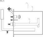
- FIG. 1 is a storage-typed hot water supply system that heats a predetermined amount of water stored in a tank 2 and retains the heat always at predetermined temperature (e.g., about 40°C).
- hot water at predetermined temperature is supplied while the storage amount of water is discharged; however, the hot water gradually decreases in temperature and hot water under the predetermined temperature is discharged, when the system is used for a long time above the storage amount of water, such that it has a limit as a hot water supply system.
- the system unnecessarily wastes electric energy and causes a sanitary problem, because it keeps the temperature for bacteria and mold to easily proliferate.
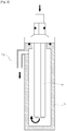
- An instantaneous-heating type fluid heating device 5 shown in FIG. 2 has been proposed, which uses a cylindrical ceramic heater in order to remove the defects of the storage-typed hot water supply system.
- the fluid heating device 5 has the advantage of discharging hot water at predetermined temperature for a long time, because it can instantaneously heat the water (or fluid) flowing into a heating tank 7 through the cylindrical ceramic heater 6 at predetermined temperature, using electric heat from the ceramic heater 6.
- the oxygen dissolved in the water cannot be instantaneously dissolved and a large amount of very small bubbles are generate due to the instantaneous heating.
- the bubbles can be discharged with the flow of water at high flow speed; however, the bubbles collect and remain on the surface of the ceramic heater and easily develop in a large bubble.
- the large bubble developed from the bubbles collecting and remaining on the surface of the ceramic heater causes local thermal non-uniformity and a thermal shock in the ceramic heater, such that the ceramic heater is broken.
- the way of using the cylindrical ceramic heater has a fundamental problem in that the heating area is considerably reduced to increase the flow speed, whereas the flow speed on the ceramic surface is reduced to increase the heating area, due to a problem in the shape of the cylindrical ceramic heater.
- FIG. 3 shows another fluid heating device 10 proposed in the related art, in which a ceramic flat plate heater 12 is interposed between flat plate device bodies 11 and flow paths 13 are formed in the device body 11 to form a heat transfer part.
- the heating area is reduced by partitions 14 formed to forming the flow paths 13 and contacting the heating surface of the heater 12, such that the direct heating area contacting the fluid to heat is further reduced.
- a dynamic heat transfer equilibrium state in which an inlet and an outlet of water is formed through a single ceramic heating surface may increase temperature difference in the ceramic plate heater, such that it is difficult to increase the size.
- the size is reduced, it is required to increase the internal pressure for passing a predetermined amount of fluid due to the reduction of heat transfer area caused by forming the flow paths. Further, it is required to increase an output density per unit area.
- fluid enters one side of the plate ceramic heater, flows to the opposite side through a plurality of flow paths formed on the heating surface, and then flows into a hot water sub-tank through a plurality of flow paths formed by copperplates on the opposite heating surface.
- heat transfer is implemented through copperplates between the hot water sub-tank and the flow paths passing through the last heating surface entering hot water sub-tank.
- thermal non-uniformity is increased by the structure that reduces the heating surface, increases a difference in temperature of one heating plate, and have a difficulty in removing the bubbles generated, such that a problem may occur in durability and safety of the ceramic heater.
- the improved structure of the flat plate ceramic heater does not reduce the heating surface because the walls forming the flow paths does not contact the heating surface; however, the response may decreases due to the structure that heats the hot water sub-tank with one heater.
- local flow speed reduction sections are easily formed by the copperplate for heat transfer and flow rate division and bubble are easily generated from the oxygen dissolved in the water in instantaneous heating, and collected and developed, such that the ceramic heater may be easily exposed to a thermal shock.
- the present invention was designed to overcome the problems, it is an object of the present invention to provide a fluid heating device according to claim 1 that can improve heating efficiency by maximizing the heat transfer surface between a heater and fluid with a small volume such that the fluid can rapidly reach predetermined temperature by instantaneous heating.
- the present invention includes one or a plurality of ceramic heaters having a heating electrode having predetermined resistance in a ceramic insulator, a heating flow path is formed on the heating surfaces of the heaters for fluid to transfer heat, and the heating flow path can sufficiently increase the area contacting the heating surface per unit volume of the fluid, such that it is possible to increase heat transfer efficiency.
- the heating resistor is positioned in the ceramic insulator, such that it can be insulated from fluid, such as water, and has two heating surfaces for transferring heat at high output density. Accordingly, the flow of fluid horizontally moving along one heating surface and then passing the opposite heating surface can maintain a relative high flow speed; however, the heating surface contact area per unit volume of the flow path is large, such that the fluid can sufficiently transfer heat by remaining on the heating surface as long as possible.
- the present invention having this configuration has rapid response and can be manufactured in a small size, such that it can be continuously used for a long time. Further, it is possible to prevent the ceramic heater from being exposed to a thermal shock by keeping the flow speed above a predetermined level while maintaining the heating area. Furthermore, it is possible to maintain uniform temperature in the ceramic heater and device in a dynamic normal state heating the fluid. In addition, it is possible to achieve safety and durability for the device by optimizing the device such that the fluid can efficiently transfer heat with the surface of the ceramic heater.
- the present invention relates to a fluid heating device having a heat-transfer structure that is efficient and has small thermal capacity by increasing an area ratio of a heating surface per unit volume of fluid, and is useful for devices required to simply change temperature of fluid, because it is possible to rapidly heat the fluid at temperature instantaneously set.
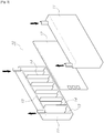
- a flat plate ceramic heater 102 with terminal lead wires 101 for supplying power exposed to the outside at the center is disposed at the center, and partition plates 105 and flow path forming plates 106 for forming fluid pathways through which fluid to heat flows to the ceramic heater 102 and is discharged after passing through the ceramic heater 102 are formed above and under the ceramic heater 102.
- a pathway hole 108 is formed in the partition plate 105 such that a fluid pathway 107 allowing fluid to horizontally move, and a fluid pathway 109 is formed through the side opposite to the lead wire 101 of the ceramic heater 102 and flow path forming plate 106 such that the fluid can move to the fluid pathway 107 of the next layer.
- the fluid pathway 109 is alternately formed left and right in the figure, not in the same direction in consideration of zigzag flow of the fluid and it is apparent that the number of the partition plate 105 and the flow path forming plate 106 which are stacked in a multiple layer can be increased and decreased.
- An upper cover 111 having an inlet hole 110 for supplying the fluid to heat and a lower cover 113 having an outlet hole 112 for discharging heated fluid are disposed at the outside of the uppermost and lowermost partition plates 105, respectively.
- the fluid heating device 100 may be made of ceramic in consideration of durability, but the partition plate 105, the flow path forming plate 106, and the upper and lower covers 111, 113, except for the ceramic heater 102, may be metal, nonmetal, or heat-resistant plastic in consideration of improving productivity and reducing the cost.
- partition plates 105, the flow path forming plates 106, and the upper and lower covers 111, 113 are independently formed in the present invention
- the configuration may be implemented in various ways, such as integrally forming the others, except for the ceramic heater 102, integrally forming the partition plates 105 and the flow path forming plates 106, integrally forming the partition plates 105, the flow path forming plates 106, and the upper covers 111, or integrally forming the partition plates 105, the flow path forming plates 106, and the lower cover 113.
- the fluid pathway formed by the partition plate 105 and the flow path forming plate 106 which are adjacent to the ceramic heater 102 is a heating flow path 115 where the fluid is directly heated by the ceramic heater 102, such that a process of heating the fluid, using predetermined heat transfer occurs in the heating flow path 115.
- the aspect ratio of the cross-sectional area of the heating flow path 115 is important for effectively transmitting energy, which is applied to the fluid from the heating surface (ceramic heater), to the fluid per unit volume. Reducing the aspect ratio, such as a cube or a circle, has the advantage of passing a large amount of fluid at low pressure, because the cross-sectional ratio of the flow path per unit volume is large.
- the transmission speed of heat from the heating surface to the center of the heating flow path is low, such that temperature difference of the fluid increases in the temperature distribution on the cress section of the flow path and heat transfer efficiency decreases.
- the heating surface simultaneously contacts liquid having high thermal capacity and gases having low thermal capacity, such that a portion of the heating surface contacting only the gases rapidly increases in temperature and rapid temperature difference occurs at the portion, and accordingly, it is exposed to a thermal shock.
- the aspect ratio of the cross-sectional area of the heating flow path is large (preferably, w/h > 3)
- the area of the heating area per unit volume increases and the flow speed per unit flow rate increases, which, subsequently, reduces temperature difference of the fluid in the temperature distribution in the cross-sectional area of the heating flow path and derives efficient heat transfer while removing opportunities for bubble collection and bubble development on the heating surface. Therefore, it is possible to achieve a very stable structure for heat transfer by preventing breakage of the ceramic heater.
- a fluid heating device not forming part of the invention, having a heating flow path that has 140mm (70mm X both sides) length '1' and a heating surface that is 20mm wide and 1mm high.
- the aspect ratio of the heating flow path is 20, the total volume of the heating flow path is 2, 800mm 3 , and the heating area is 2, 800mm 2 .
- the total volume is 7,596mm 3 and the heating area is 3,627mm 2 in the heating flow path.
- the area/volume ratio is 1mm -1 in the fluid heating device having a large aspect ratio and 0.48mm -1 in the fluid heating device having a circular tube ceramic heater; therefore, the larger the aspect ratio, the more the heating area per volume can be increased.
- the distance between the heating surface and the center of the flow path is 0.5mm in the fluid heating device having an aspect ratio of 20, whereas it is 3.25mm and 2mm for the inner surface and the outer surface, respectively, in the fluid heating device having a circular tube ceramic heater.
- the distance depending on convection in the fluid having a heat transfer rate larger than conduction increases, such that the heat transfer efficiency may considerably decrease, and possibility of bubble generation on the heating surface of the circular tube ceramic heater increases and possibility of exposure to a thermal shock increases.
- the thermal efficiency can be increased by reducing the distance between the heating surface and the center of the flow path and high reliability can be achieved by reducing the possibility to be exposed to a thermal shock in the heating surface.
- the ceramic heater can transfer a large amount of heat by conduction, because it is manufactured by disposing the heating surface of a metal resistor in a ceramic material, which is an insulator, such that the ceramic heater has excellent properties as a high-speed heating unit.
- this ability may be vulnerable to a thermal shock, because the structure is formed by ceramic. Therefore, it is required to use a ceramic heater having a larger area, because heat output per unit area should be appropriately limited, when higher heating capacity is required.
- a fluid heating device having a heating flow path that has 420mm (70mm X both sides X 3 heaters) length '1' and a heating surface that is 20mm wide and 1mm high.
- the aspect ratio of the heating flow path is 20, the total volume of the heating flow path is 5,600(4 X 1,400)mm3, and the heating area is 8,400(6 X 1,400)mm 2 .
- the area/volume ratio is 1.5mm -1 , which increases about 3.1 times, as compared with that the fluid heating device having a circular tube ceramic heater has the area/volume ratio of 0.48mm -1 , such that it can bee seen that the heating efficiency can be efficiently increased.
- the most important part in the fluid heating device 100 is the ceramic heater 102, which is a heater showing good heating performance in "conduction”, which fastest transfers heat among radiation, convection, and conduction, which are general ways of transferring heat.
- a method of manufacturing the ceramic heater 102 which can be applied to the present invention is various and not specifically limited, a typical method is to manufacture a ceramic heater, using co-firing.
- the ceramic used for this configuration is a compound generally containing Al 2 O 3 96% with a small amount of SiO2, CaO, MgO, Na 2 O, K 2 , O, and the metal used for the heat resistor is usually metal having a high meting point, such as W and Mo.
- the circular tube ceramic heater which does not form part of the invention is usually manufactured by co-firing, which uses green sheets, and may be manufactured by rolling and co-firing a green sheet applied with heat resistors around a quasi-sintered ceramic tube.
- a ceramic heater similar to the ceramic heater manufactured by co-firing by applying, driving, and sintering metal plate, as a heat resistor, to one sintered ceramic substrate, applying, driving, and removing an adhesive to another sintered ceramic substrate, and then bonding and sintering the substrates.
- the heat resistor may be metal paste mainly containing metal, such as W and Mo, which is metal having a high melting point and metal paste, such as Ag, Ag-Pd, RuO 2 , Pd, and Pt, which is metal having a low melting point and low temperature resistance coefficient.
- Ceramic sintered substrates that are generally used and inexpensive contain Al 2 O 3 as the main component, and various kinds of ceramic substrates can be used as thermal shock-resistant materials, including an AIN sintered substrate, SiC sintered substrate, and Si 3 N 4 sintered substrate.
- the surfaces contacting the partition plates 105 of the ceramic heater 102 and the flow path forming plates 106 are applied and removed with a glass adhesive, and both sides of the partition plates 105 are also applied and remove with a glass adhesive.
- the fluid heating device 100 that is generally sintering-bonded by stacking the parts, calcining or sintering them at temperature where the glass adhesive can be molten and bonded.
- the shape of the inlet hole 110 and the outlet hole 112 through which the fluid flows into/out of the fluid heating device 100 is not specifically limited, it is possible to mold nuts or tubes which is made of various materials into holes, or house the fluid heating device 100 of the present invention into a case equipped with a case.
- the features of the fluid heating device 100 may be modified such that the cylindrical ceramic heater 160 can have a large aspect ratio.
- a cylindrical ceramic heater does not form part of the invention.
- a flow path forming tube 162 is inserted in the cylindrical ceramic heater 160 combined with the case 161 having the inlet hole 110 and the outlet hole 112 for the fluid to flow inside and outside such that the flow flows inside the inner circumference of the flow path forming tube 162, exits along outer circumference of the flow path forming tube 162 and the inner circumference of the cylindrical ceramic heater 160, and the is discharged outside along the outer circumference of the cylindrical ceramic heater 160 again.
- the width 'w' of the flow path contacting the heating surface is ⁇ (r 2 +r 1 ) and the aspect ratio when the fluid exits is ⁇ (r 2 +r 1 ) ⁇ (r 2 +r 1 ).
- the aspect ratio is 12.6 and the cross-sectional area of the flow path is 201.
- the heating surface is usually formed close to the outer circumference of the cylindrical ceramic heater and a very small gap is defined at a surface contacting the heating surface, such that it is possible to maximize a heating area per unit volume and expect high thermal efficiency.
- a fluid heating device not forming part of the invention is configured, in which a cylindrical ceramic heater having heating resistance of 20 ⁇ , an inner diameter of 6.5mm, an outer diameter of 10mm, a heating length of 80mm was used and a flow path forming plate (5mm outer diameter and 4mm inner diameter) was inserted inside the inner circumference.
- the inner diameter of a case was set to 12mm such that the aspect ratio of the flow path in the inner circumference was 24 and the aspect ratio of the outer circumference was 34.5, in this device.
- a voltage of 220V was applied and water flowed at a flow rate of 1 ⁇ 1.2L per minute.
- the water having initial temperature of 25°C was continuously heated by 45 ⁇ 50°C and this heating experiment was continued for about 3000 hours (125daysX24hr), but the inner ceramic heater was not broken.
- Vapor at 120 ⁇ 200°C was produced at the outlet hole by power of 150 ⁇ 250W by injecting mist (about 1g water/L, air containing micro-drops of water produced by ultrasonic vibration) at 10 LPM and applying a voltage of 220V to the terminal of the series of ceramic heaters.
- the water having initial temperature of 25DC was continuously heated by 44 ⁇ 46°C, power of 1.8kW was consumed, and the ceramic heater was broken in about 480 hours (20daysX24hr).
- the present invention described above is expected to be widely used in an apparatus for cleaning a part of a human body, an instantaneous hot water supply system for home, a radiator for heating, and an apparatus for heating circulating water for heating.
- the present invention it is possible to instantaneously heat liquid and instantaneously convert the liquid into vapor by the heating, such that it is possible to easily produce vapor. Further, a wide use is expected, such as, for a cooker, a sterilizer, and an evaporator.
Landscapes
- Engineering & Computer Science (AREA)
- Physics & Mathematics (AREA)
- Thermal Sciences (AREA)
- Chemical & Material Sciences (AREA)
- Combustion & Propulsion (AREA)
- Mechanical Engineering (AREA)
- General Engineering & Computer Science (AREA)
- Instantaneous Water Boilers, Portable Hot-Water Supply Apparatuses, And Control Of Portable Hot-Water Supply Apparatuses (AREA)
- Details Of Fluid Heaters (AREA)
- Resistance Heating (AREA)
Description
- The present invention relates to a fluid heating device, in more detail, a small-sized fluid heating device that can instantaneously heat fluid flowing for supply or circulation, due to high heating efficiency.
- A typical fluid heating device 1 is shown in
FIG. 1 , which is a storage-typed hot water supply system that heats a predetermined amount of water stored in a tank 2 and retains the heat always at predetermined temperature (e.g., about 40°C). - Because the storage amount is limited in the storage-typed hot water supply system, hot water at predetermined temperature is supplied while the storage amount of water is discharged; however, the hot water gradually decreases in temperature and hot water under the predetermined temperature is discharged, when the system is used for a long time above the storage amount of water, such that it has a limit as a hot water supply system.
- That is, it is limitative to use the system because the use time is limited and it is required to intermittently operate the system in order to supply hot water at predetermined temperature and keep the temperature.
- Further, it is required to increase the size of the tank to ensure a predetermined storage amount and accordingly the system increases in size. It is also required to continuously supply electric power such that the temperature of the tank having predetermined heat loss is maintained in order to use the system at anytime. Therefore, the system unnecessarily wastes electric energy and causes a sanitary problem, because it keeps the temperature for bacteria and mold to easily proliferate.
- An instantaneous-heating type
fluid heating device 5 shown inFIG. 2 has been proposed, which uses a cylindrical ceramic heater in order to remove the defects of the storage-typed hot water supply system. - The
fluid heating device 5 has the advantage of discharging hot water at predetermined temperature for a long time, because it can instantaneously heat the water (or fluid) flowing into a heating tank 7 through the cylindricalceramic heater 6 at predetermined temperature, using electric heat from theceramic heater 6. - However, it is difficult to accurately manufacture the cylindrical ceramic heater in order to reduce the diameter and the heating area is correspondingly reduced, such that it needs to maintain the size above a predetermined level. Meanwhile, when the heating area is large, the cross section of the flow path increases and the flow speed decreases, such that heat transfer efficiency is reduced and the thermal efficiency of the fluid heating device is correspondingly reduced.
- In addition, it is limitative to reduce the size because of the dimension of the cylindrical ceramic heater and. Further, a predetermined amount of water is naturally stored, such that the control response becomes low and it is difficult to rapidly change the predetermined temperature.
- In particular, the oxygen dissolved in the water cannot be instantaneously dissolved and a large amount of very small bubbles are generate due to the instantaneous heating. The bubbles can be discharged with the flow of water at high flow speed; however, the bubbles collect and remain on the surface of the ceramic heater and easily develop in a large bubble.
- The large bubble developed from the bubbles collecting and remaining on the surface of the ceramic heater causes local thermal non-uniformity and a thermal shock in the ceramic heater, such that the ceramic heater is broken.
- In order to prevent these problems, there has been effort of applying hydrophilic oxide on the surface of the ceramic heater such that to prevent the bubbles from developing on the surface. However, this method cannot be a basic solution, because various deposits are attached to the surface when it is used for a long period of time.
- Further, the way of using the cylindrical ceramic heater has a fundamental problem in that the heating area is considerably reduced to increase the flow speed, whereas the flow speed on the ceramic surface is reduced to increase the heating area, due to a problem in the shape of the cylindrical ceramic heater.
-
FIG. 3 shows anotherfluid heating device 10 proposed in the related art, in which a ceramicflat plate heater 12 is interposed between flat plate device bodies 11 andflow paths 13 are formed in the device body 11 to form a heat transfer part. - According to the
fluid heating device 10, although it is possible to achieve a small-sized device by implementing heat transfer through the flow paths formed in predetermined heating areas, the heating area is reduced bypartitions 14 formed to forming theflow paths 13 and contacting the heating surface of theheater 12, such that the direct heating area contacting the fluid to heat is further reduced. - A dynamic heat transfer equilibrium state in which an inlet and an outlet of water is formed through a single ceramic heating surface may increase temperature difference in the ceramic plate heater, such that it is difficult to increase the size. However, when the size is reduced, it is required to increase the internal pressure for passing a predetermined amount of fluid due to the reduction of heat transfer area caused by forming the flow paths. Further, it is required to increase an output density per unit area.
- Another similar configuration has been proposed, but, in which heat transfer is made while fluid flows through a plurality of flow paths arrange in parallel on one surface from the center of one flat plate ceramic heater and returns and flows through a plurality of flow paths formed on the opposite heating surface.
- According to this configuration, fluid enters one side of the plate ceramic heater, flows to the opposite side through a plurality of flow paths formed on the heating surface, and then flows into a hot water sub-tank through a plurality of flow paths formed by copperplates on the opposite heating surface. In this structure, heat transfer is implemented through copperplates between the hot water sub-tank and the flow paths passing through the last heating surface entering hot water sub-tank.
- It is difficult to reduce the size of the storage-typed hot water supply system of the related art and the capacity that can be immediately used is limited. Electric power loss continuously occurs while the system is not used and the tank may be constantly exposed to insanitation state.
- Although it is possible to slightly reduce the size and improve the response, but it is also limitative, in the instantaneous-heating type hot water supply system using a ceramic heater having high heating output in order to overcome the problems in the storage-typed hot water supply system. A structure that can improve thermal non-uniformity because the ceramic heater is vulnerable to a thermal shock is required; however, the cylindrical ceramic heater has problems, such as limitative heating response and thermal shock breakage due to development of bubbles, such that it is limitative to improve the heating output.
- In a flat plate ceramic heater that is another configuration of the instantaneous-heating type, thermal non-uniformity is increased by the structure that reduces the heating surface, increases a difference in temperature of one heating plate, and have a difficulty in removing the bubbles generated, such that a problem may occur in durability and safety of the ceramic heater.
- Further, the improved structure of the flat plate ceramic heater does not reduce the heating surface because the walls forming the flow paths does not contact the heating surface; however, the response may decreases due to the structure that heats the hot water sub-tank with one heater.
- In addition, local flow speed reduction sections are easily formed by the copperplate for heat transfer and flow rate division and bubble are easily generated from the oxygen dissolved in the water in instantaneous heating, and collected and developed, such that the ceramic heater may be easily exposed to a thermal shock.
- In particular, in documents
JP2002083672A WO00/42360A1 - The present invention was designed to overcome the problems, it is an object of the present invention to provide a fluid heating device according to claim 1 that can improve heating efficiency by maximizing the heat transfer surface between a heater and fluid with a small volume such that the fluid can rapidly reach predetermined temperature by instantaneous heating.
- The present invention includes one or a plurality of ceramic heaters having a heating electrode having predetermined resistance in a ceramic insulator, a heating flow path is formed on the heating surfaces of the heaters for fluid to transfer heat, and the heating flow path can sufficiently increase the area contacting the heating surface per unit volume of the fluid, such that it is possible to increase heat transfer efficiency.
- In the ceramic heater, the heating resistor is positioned in the ceramic insulator, such that it can be insulated from fluid, such as water, and has two heating surfaces for transferring heat at high output density. Accordingly, the flow of fluid horizontally moving along one heating surface and then passing the opposite heating surface can maintain a relative high flow speed; however, the heating surface contact area per unit volume of the flow path is large, such that the fluid can sufficiently transfer heat by remaining on the heating surface as long as possible.
- The present invention having this configuration has rapid response and can be manufactured in a small size, such that it can be continuously used for a long time. Further, it is possible to prevent the ceramic heater from being exposed to a thermal shock by keeping the flow speed above a predetermined level while maintaining the heating area. Furthermore, it is possible to maintain uniform temperature in the ceramic heater and device in a dynamic normal state heating the fluid. In addition, it is possible to achieve safety and durability for the device by optimizing the device such that the fluid can efficiently transfer heat with the surface of the ceramic heater.
- The present invention relates to a fluid heating device having a heat-transfer structure that is efficient and has small thermal capacity by increasing an area ratio of a heating surface per unit volume of fluid, and is useful for devices required to simply change temperature of fluid, because it is possible to rapidly heat the fluid at temperature instantaneously set.
- Further, it is possible to achieve high reliability and continuous use, because of the heat-transfer structure that can improve patent performance against a thermal shock while using high-efficiency and high-output ceramic heater.
- Therefore, it is possible to reduce the size without a hot water storing tank and prevents unnecessary loss of power, such that there are many advantages to reduce power consumption.
-
-
FIG. 1 is a cross-sectional view showing the configuration of a first embodiment of a fluid heating device according to the related art; -
FIG. 2 is a cross-sectional view showing the configuration of a second embodiment of a fluid heating device according to the related art; -
FIG. 3 is a cross-sectional view showing the configuration of a third embodiment of a fluid heating device according to the related art; -
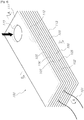
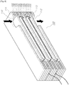
FIG. 4 is a perspective view showing a first embodiment of a fluid heating device according to the present invention; -
FIG. 5 is a cross-sectional view of the fluid heating device according to the present invention, taken along line A-A; -
FIG. 6 is a cross-sectional view of the fluid heating device according to the present invention, taken along line B-B; -
FIG. 7 is an exploded perspective view showing the fluid heating device according to the present invention; -
FIG. 8 is a perspective view showing a second embodiment of a fluid heating device according to the present invention; -
FIG. 9 is a perspective view showing a fluid heating device not forming part of the present invention; -
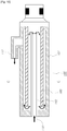
FIG. 10 is a cross-sectional view showing a fluid heating device not forming part of the present invention; and -
FIG. 11 is a cross-sectional view of the fluid heating device shown inFIG. 10 , taken along line C-C. - In a
fluid heating device 100 according to the present invention, a flat plateceramic heater 102 withterminal lead wires 101 for supplying power exposed to the outside at the center is disposed at the center, andpartition plates 105 and flowpath forming plates 106 for forming fluid pathways through which fluid to heat flows to theceramic heater 102 and is discharged after passing through theceramic heater 102 are formed above and under theceramic heater 102. - A
pathway hole 108 is formed in thepartition plate 105 such that afluid pathway 107 allowing fluid to horizontally move, and afluid pathway 109 is formed through the side opposite to thelead wire 101 of theceramic heater 102 and flowpath forming plate 106 such that the fluid can move to thefluid pathway 107 of the next layer. - It is preferable that the
fluid pathway 109 is alternately formed left and right in the figure, not in the same direction in consideration of zigzag flow of the fluid and it is apparent that the number of thepartition plate 105 and the flowpath forming plate 106 which are stacked in a multiple layer can be increased and decreased. - An
upper cover 111 having aninlet hole 110 for supplying the fluid to heat and alower cover 113 having anoutlet hole 112 for discharging heated fluid are disposed at the outside of the uppermost andlowermost partition plates 105, respectively. - The
fluid heating device 100 may be made of ceramic in consideration of durability, but thepartition plate 105, the flowpath forming plate 106, and the upper andlower covers ceramic heater 102, may be metal, nonmetal, or heat-resistant plastic in consideration of improving productivity and reducing the cost. - Further, although the
partition plates 105, the flowpath forming plates 106, and the upper andlower covers ceramic heater 102, integrally forming thepartition plates 105 and the flowpath forming plates 106, integrally forming thepartition plates 105, the flowpath forming plates 106, and the upper covers 111, or integrally forming thepartition plates 105, the flowpath forming plates 106, and thelower cover 113. - The fluid pathway formed by the
partition plate 105 and the flowpath forming plate 106 which are adjacent to theceramic heater 102 is aheating flow path 115 where the fluid is directly heated by theceramic heater 102, such that a process of heating the fluid, using predetermined heat transfer occurs in theheating flow path 115. - The most remarkable feature of the
fluid heating device 100 of the present invention is that a cross-sectional area is defined by the height 'h' of thepartition plate 105 and the width 'w' of the heating surface of the flat plateceramic heater 102, that is, the height 'h' and the width 'w' of theheating flow path 115 and the aspect ratio 'r' of theheating flow path 115 may be defined as follow.
- The aspect ratio of the cross-sectional area of the
heating flow path 115 is important for effectively transmitting energy, which is applied to the fluid from the heating surface (ceramic heater), to the fluid per unit volume. Reducing the aspect ratio, such as a cube or a circle, has the advantage of passing a large amount of fluid at low pressure, because the cross-sectional ratio of the flow path per unit volume is large. - However, the transmission speed of heat from the heating surface to the center of the heating flow path is low, such that temperature difference of the fluid increases in the temperature distribution on the cress section of the flow path and heat transfer efficiency decreases.
- Further, a large amount of bubbles are generated on the heating surface in the
fluid heating device 100, in which bubbles collecting on the heating surface are likely to develop, because the temperature difference is large for the cross-sectional area having a small aspect ratio and the fluid passes the heating surface at a relatively low speed. - Although it is known that as the temperature of the fluid increases, the gases which are generally dissolved in water, including oxygen, decrease in solubility and are liquated, the bubbles generated in the
heating flow path 115 have difficulty in collecting on the heating surface at a high flow speed, whereas the bubbles collect on the ceramic heating surface and develop at a low flow speed.\ When the volume of the gases collecting on the heating surface increases, the heating surface simultaneously contacts liquid having high thermal capacity and gases having low thermal capacity, such that a portion of the heating surface contacting only the gases rapidly increases in temperature and rapid temperature difference occurs at the portion, and accordingly, it is exposed to a thermal shock. - On the contrary, when the aspect ratio of the cross-sectional area of the heating flow path is large (preferably, w/h > 3), the area of the heating area per unit volume increases and the flow speed per unit flow rate increases, which, subsequently, reduces temperature difference of the fluid in the temperature distribution in the cross-sectional area of the heating flow path and derives efficient heat transfer while removing opportunities for bubble collection and bubble development on the heating surface. Therefore, it is possible to achieve a very stable structure for heat transfer by preventing breakage of the ceramic heater.
- For example, assume a fluid heating device not forming part of the invention, having a heating flow path that has 140mm (70mm X both sides) length '1' and a heating surface that is 20mm wide and 1mm high.
- The aspect ratio of the heating flow path is 20, the total volume of the heating flow path is 2, 800mm3, and the heating area is 2, 800mm2. Meanwhile, for a fluid heating device including a case having a 14mm diameter in which a circular tube ceramic heater having a 6.5mm inner diameter, a 10mm diameter, and a 140mm (70 X (inner diameter + outer diameter)) length of a heating flow path, the total volume is 7,596mm3 and the heating area is 3,627mm2 in the heating flow path.
- The area/volume ratio is 1mm-1 in the fluid heating device having a large aspect ratio and 0.48mm-1 in the fluid heating device having a circular tube ceramic heater; therefore, the larger the aspect ratio, the more the heating area per volume can be increased. Further, the distance between the heating surface and the center of the flow path is 0.5mm in the fluid heating device having an aspect ratio of 20, whereas it is 3.25mm and 2mm for the inner surface and the outer surface, respectively, in the fluid heating device having a circular tube ceramic heater.
- Accordingly, the distance depending on convection in the fluid having a heat transfer rate larger than conduction increases, such that the heat transfer efficiency may considerably decrease, and possibility of bubble generation on the heating surface of the circular tube ceramic heater increases and possibility of exposure to a thermal shock increases.
- On the contrary, according to the structure provided by the present invention, the thermal efficiency can be increased by reducing the distance between the heating surface and the center of the flow path and high reliability can be achieved by reducing the possibility to be exposed to a thermal shock in the heating surface.
- The ceramic heater can transfer a large amount of heat by conduction, because it is manufactured by disposing the heating surface of a metal resistor in a ceramic material, which is an insulator, such that the ceramic heater has excellent properties as a high-speed heating unit.
- On the other hand, this ability may be vulnerable to a thermal shock, because the structure is formed by ceramic. Therefore, it is required to use a ceramic heater having a larger area, because heat output per unit area should be appropriately limited, when higher heating capacity is required.
- However, when a single ceramic substrate has a large area, it is a more efficient design to use a plurality of ceramic heater, because the limit of heat output per unit area decreases.
- In this case, it is possible to effectively increase the heating area by alternately stacking flow
path forming plates 106 with a plurality ofceramic heaters 12 therebetween and insertingpartition plates 105 between them. In addition, it is possible to effectively increase the heat output by replacing the flow path forming plate 130 with theceramic heater 102, because it is possible to achieve a larger heating area with the same flow path volume. - As an example using a plurality of
ceramic heater 102, assume a fluid heating device having a heating flow path that has 420mm (70mm X both sides X 3 heaters) length '1' and a heating surface that is 20mm wide and 1mm high. - The aspect ratio of the heating flow path is 20, the total volume of the heating flow path is 5,600(4 X 1,400)mm3, and the heating area is 8,400(6 X 1,400)mm2. In the fluid heating device having this configuration, the area/volume ratio is 1.5mm-1, which increases about 3.1 times, as compared with that the fluid heating device having a circular tube ceramic heater has the area/volume ratio of 0.48mm-1, such that it can bee seen that the heating efficiency can be efficiently increased.
- The most important part in the
fluid heating device 100 is theceramic heater 102, which is a heater showing good heating performance in "conduction", which fastest transfers heat among radiation, convection, and conduction, which are general ways of transferring heat. - Good heat transfer features are achieved because an object to heat is heated by direct contact, by the most directly insulating the conductive heat resistor in the electric heating device using electricity.
- Although a method of manufacturing the
ceramic heater 102 which can be applied to the present invention is various and not specifically limited, a typical method is to manufacture a ceramic heater, using co-firing. - It is to apply heat resistors to one ceramic green sheet and laminate another ceramic sheet, and co-fire the heat resistors applied in the ceramic sheet.
- The ceramic used for this configuration is a compound generally containing Al2O3 96% with a small amount of SiO2, CaO, MgO, Na2O, K2, O, and the metal used for the heat resistor is usually metal having a high meting point, such as W and Mo.
- The circular tube ceramic heater which does not form part of the invention is usually manufactured by co-firing, which uses green sheets, and may be manufactured by rolling and co-firing a green sheet applied with heat resistors around a quasi-sintered ceramic tube.
- Similarly, according to another method, it is possible to manufacture a ceramic heater similar to the ceramic heater manufactured by co-firing, by applying, driving, and sintering metal plate, as a heat resistor, to one sintered ceramic substrate, applying, driving, and removing an adhesive to another sintered ceramic substrate, and then bonding and sintering the substrates.
- When a metal resistor is disposed between two sintered ceramic substrates and bonding-sintering is performed with a glass-ceramic sintered adhesive or a glass adhesive, the heat resistor may be metal paste mainly containing metal, such as W and Mo, which is metal having a high melting point and metal paste, such as Ag, Ag-Pd, RuO2, Pd, and Pt, which is metal having a low melting point and low temperature resistance coefficient.
- Ceramic sintered substrates that are generally used and inexpensive contain Al2O3 as the main component, and various kinds of ceramic substrates can be used as thermal shock-resistant materials, including an AIN sintered substrate, SiC sintered substrate, and Si3N4 sintered substrate.
- When the parts of the
fluid heating device 100 where the present invention is applied are made of ceramic, the surfaces contacting thepartition plates 105 of theceramic heater 102 and the flowpath forming plates 106 are applied and removed with a glass adhesive, and both sides of thepartition plates 105 are also applied and remove with a glass adhesive. - Further, it is possible to achieve the
fluid heating device 100 that is generally sintering-bonded by stacking the parts, calcining or sintering them at temperature where the glass adhesive can be molten and bonded. - Although the shape of the
inlet hole 110 and theoutlet hole 112 through which the fluid flows into/out of thefluid heating device 100 is not specifically limited, it is possible to mold nuts or tubes which is made of various materials into holes, or house thefluid heating device 100 of the present invention into a case equipped with a case. - The features of the
fluid heating device 100 may be modified such that the cylindricalceramic heater 160 can have a large aspect ratio. A cylindrical ceramic heater, however, does not form part of the invention. - A flow
path forming tube 162 is inserted in the cylindricalceramic heater 160 combined with thecase 161 having theinlet hole 110 and theoutlet hole 112 for the fluid to flow inside and outside such that the flow flows inside the inner circumference of the flowpath forming tube 162, exits along outer circumference of the flowpath forming tube 162 and the inner circumference of the cylindricalceramic heater 160, and the is discharged outside along the outer circumference of the cylindricalceramic heater 160 again. - In this case, it is also possible to achieve a high aspect ratio and the flow direction of the fluid may be reversed.
- In the fluid heating device including the cylindrical
ceramic heater 160 where the technology of the present invention is applied, the width 'w' of the flow path contacting the heating surface (cylindrical ceramic heater) is π× (r2+r1) and the aspect ratio when the fluid exits is π× (r2+r1)□(r2+r1). - For example, when r1 is 10 and r2 is 6, the aspect ratio is 12.6 and the cross-sectional area of the flow path is 201.
- When the cross-sectional area of the flow path formed on the outer circumference of the cylindrical ceramic heater is made the same (for the same flow speed), r2 is 14.5, r1 is 12, and the aspect ratio is 33.3.
- The heating surface is usually formed close to the outer circumference of the cylindrical ceramic heater and a very small gap is defined at a surface contacting the heating surface, such that it is possible to maximize a heating area per unit volume and expect high thermal efficiency.
- A fluid heating device was configured such that a heating area was 7.5cm2[=50X15], two plate ceramic heaters having heating resistance of 35Ω were connected in parallel, and the cross-sectional areas of horizontal and vertical flow paths were 0.32cm2[=2mm(h)X16mm (w, heating surface), w/h=8].
- When a voltage of 220V was applied and water continuously flowed at a flow rate of 1 ∼ 1.2L per minute, the water having initial temperature of 25°C was continuously heated by 50∼55°C and power of 2.2kW was consumed. This heating experiment was continued for about 5000 hours (210daysX24hr), but the inner ceramic heater was not broken.
- A fluid heating device not forming part of the invention is configured, in which a cylindrical ceramic heater having heating resistance of 20Ω, an inner diameter of 6.5mm, an outer diameter of 10mm, a heating length of 80mm was used and a flow path forming plate (5mm outer diameter and 4mm inner diameter) was inserted inside the inner circumference.
- The inner diameter of a case was set to 12mm such that the aspect ratio of the flow path in the inner circumference was 24 and the aspect ratio of the outer circumference was 34.5, in this device. A voltage of 220V was applied and water flowed at a flow rate of 1 ∼ 1.2L per minute.
- The water having initial temperature of 25°C was continuously heated by 45∼50°C and this heating experiment was continued for about 3000 hours (125daysX24hr), but the inner ceramic heater was not broken.
- A fluid heating device not forming part of the invention was configured such that a heating area was 7.5cm2[=50X15], four plate ceramic heaters having heating resistance of 40Ω were connected in series, and the cross-sectional areas of horizontal and vertical flow paths were 0.08cm2[=0.5mm(h)X16mm (w, heating surface), w/h=32].
- Vapor at 120∼200°C was produced at the outlet hole by power of 150∼250W by injecting mist (about 1g water/L, air containing micro-drops of water produced by ultrasonic vibration) at 10 LPM and applying a voltage of 220V to the terminal of the series of ceramic heaters.
- A fluid heating device using a tube type ceramic heater of the related art having heating resistance of 20Ω, an inner diameter of 6.5mm, an outer diameter of 10mm, a heating length of 80mm, a voltage of 220V was applied, and water continuously flowed at a flow rate of 1 ∼ 1.2L per minute
- The water having initial temperature of 25DC was continuously heated by 44∼46°C, power of 1.8kW was consumed, and the ceramic heater was broken in about 480 hours (20daysX24hr).
- The present invention described above is expected to be widely used in an apparatus for cleaning a part of a human body, an instantaneous hot water supply system for home, a radiator for heating, and an apparatus for heating circulating water for heating.
- Further, according to the present invention, it is possible to instantaneously heat liquid and instantaneously convert the liquid into vapor by the heating, such that it is possible to easily produce vapor. Further, a wide use is expected, such as, for a cooker, a sterilizer, and an evaporator.
Claims (5)
- A fluid heating device, comprising:a flat plate ceramic heater (102) having a lead wire (101) for applying power;partition plates (105) combined and having fluid pathways through which fluid to heat flows to the ceramic heater (102) and is discharged after passing through the ceramic heater (102), above and under the ceramic heater (102);flow path forming plates (106) combined and having fluid through holes such that the fluid in the horizontal flow pathways vertically moves to the fluid pathway of the next layer;an upper cover (111) combined and having an inlet hole (110) for supplying fluid to heat in the outer surface of the uppermost partition plate (105); anda lower cover (113) combined and having an outlet hole (112) for discharging heated fluid in the outer surface of the lowermost partition plate (105).
- The fluid heating device according to claim 1, wherein the aspect ratio of the cross-sectional area of the heating flow path adjacent to the ceramic heater is set such that the width (w) is 3 or more with respect to the height (h).
- The fluid heating device according to claim 1, wherein the ceramic heaters (102) are alternately stacked to increase heating capacity.
- The fluid heating device according to claim 1, wherein the partition plate (105), the flow path forming plate (106), the upper cover (111), the lower cover (113), the case (160), or the flow path forming tube (162) is made of any one or more of sealable ceramic, plastic, metal, nonmetal.
- The fluid heating device according to claim 1, wherein
the partition plates (105), the flow path forming plates (106), the upper plate (111), and the lower cover (113), or
the partition plates (105) and the flow path forming plates (106), or
the partition plates (105) and the upper cover (111), or
the partition plates (105) and the lower cover (113) are integrally formed.
Applications Claiming Priority (2)
| Application Number | Priority Date | Filing Date | Title |
|---|---|---|---|
| KR1020080007096A KR100880773B1 (en) | 2008-01-23 | 2008-01-23 | Fluid heater |
| PCT/KR2009/000295 WO2009093832A2 (en) | 2008-01-23 | 2009-01-20 | Fluid heating device |
Publications (3)
| Publication Number | Publication Date |
|---|---|
| EP2249099A2 EP2249099A2 (en) | 2010-11-10 |
| EP2249099A4 EP2249099A4 (en) | 2016-11-30 |
| EP2249099B1 true EP2249099B1 (en) | 2018-09-05 |
Family
ID=40680866
Family Applications (1)
| Application Number | Title | Priority Date | Filing Date |
|---|---|---|---|
| EP09704296.4A Not-in-force EP2249099B1 (en) | 2008-01-23 | 2009-01-20 | Fluid heating device |
Country Status (6)
| Country | Link |
|---|---|
| US (1) | US9115912B2 (en) |
| EP (1) | EP2249099B1 (en) |
| JP (1) | JP2011510260A (en) |
| KR (1) | KR100880773B1 (en) |
| CN (1) | CN101970947B (en) |
| WO (1) | WO2009093832A2 (en) |
Cited By (1)
| Publication number | Priority date | Publication date | Assignee | Title |
|---|---|---|---|---|
| EP4456666A4 (en) * | 2021-12-20 | 2025-12-24 | Niterra Co Ltd | Liquid-heating device |
Families Citing this family (31)
| Publication number | Priority date | Publication date | Assignee | Title |
|---|---|---|---|---|
| US20050177850A1 (en) * | 1999-10-29 | 2005-08-11 | United Video Properties, Inc. | Interactive television system with programming-related links |
| KR100982702B1 (en) | 2009-06-30 | 2010-09-17 | 웅진코웨이주식회사 | Heating apparatus |
| WO2011052874A1 (en) * | 2009-10-30 | 2011-05-05 | 웅진코웨이주식회사 | Heating apparatus |
| KR101795422B1 (en) * | 2010-07-09 | 2017-11-10 | 코웨이 주식회사 | Ceramic heater and heating apparatus having the same |
| JP2012141096A (en) * | 2010-12-28 | 2012-07-26 | Mitsubishi Heavy Ind Ltd | Method for manufacturing hot-water heater, and hot-water heater manufactured thereby |
| JP5019082B1 (en) * | 2011-03-25 | 2012-09-05 | 栗田工業株式会社 | Liquid heating method, liquid heating apparatus, and heated liquid supply apparatus |
| KR101244369B1 (en) * | 2012-03-21 | 2013-03-18 | (주) 이테크 | Fluid heating structure |
| JP2014019287A (en) * | 2012-07-18 | 2014-02-03 | Sanden Corp | Heating device and manufacturing method for the same |
| JP5967760B2 (en) * | 2012-07-18 | 2016-08-10 | サンデンホールディングス株式会社 | Heating device |
| EP2689945B1 (en) * | 2012-07-24 | 2017-05-31 | MAHLE Behr GmbH & Co. KG | Heating device |
| KR101432189B1 (en) | 2013-03-04 | 2014-08-20 | 삼명엔지니어링(주) | Electric boiler utilzing fine ceramic heater |
| CN103317694A (en) * | 2013-06-30 | 2013-09-25 | 张秀英 | Temperature regulating device of injection mould |
| US10107490B2 (en) | 2014-06-30 | 2018-10-23 | Lam Research Corporation | Configurable liquid precursor vaporizer |
| US9982341B2 (en) * | 2015-01-30 | 2018-05-29 | Lam Research Corporation | Modular vaporizer |
| US11933520B2 (en) * | 2015-09-09 | 2024-03-19 | Marelli Cabin Comfort Japan Corporation | Fluid-heating device and manufacturing method thereof |
| US10662527B2 (en) * | 2016-06-01 | 2020-05-26 | Asm Ip Holding B.V. | Manifolds for uniform vapor deposition |
| KR101739807B1 (en) * | 2016-07-19 | 2017-05-26 | ㈜디에스에이치 | Fluid heating device |
| EP3726927A1 (en) * | 2016-11-07 | 2020-10-21 | Heatworks Technologies, Inc. | Devices for ohmically heating a fluid |
| KR101933170B1 (en) * | 2017-04-10 | 2019-02-01 | (주)디에스에이치 | Fluid heating device |
| DE102017121042A1 (en) * | 2017-05-24 | 2018-11-29 | Webasto SE | Liquid heater, in particular water heater |
| WO2018223035A1 (en) | 2017-06-02 | 2018-12-06 | National Machine Company | Hot water tank and flow through heating assembly |
| CN107367054A (en) * | 2017-07-10 | 2017-11-21 | 徐荣华 | Liquid heating device |
| JPWO2020175564A1 (en) * | 2019-02-28 | 2021-12-16 | 京セラ株式会社 | Heat exchange unit and cleaning equipment equipped with it |
| US11492701B2 (en) | 2019-03-19 | 2022-11-08 | Asm Ip Holding B.V. | Reactor manifolds |
| US12516414B2 (en) | 2019-03-19 | 2026-01-06 | Asm Ip Holding B.V. | Reactor manifolds |
| KR20210048408A (en) | 2019-10-22 | 2021-05-03 | 에이에스엠 아이피 홀딩 비.브이. | Semiconductor deposition reactor manifolds |
| CN111140902B (en) * | 2020-01-06 | 2022-01-28 | 陈荣才 | A heating equipment that maintenance efficiency is high for office area |
| CN112524818B (en) * | 2020-12-10 | 2022-03-22 | 芜湖美的厨卫电器制造有限公司 | Control method and control device for water heater, water heater and storage medium |
| KR102353743B1 (en) | 2021-04-14 | 2022-01-20 | 주식회사명가건축사사무소 | instant water heater |
| EP4532995A4 (en) | 2022-05-25 | 2026-05-20 | 410 Medical Inc | SYSTEMS, DEVICE AND METHOD FOR HEATING A LIQUID FOR INTRAVENOUS INFUSION |
| KR102716018B1 (en) * | 2022-08-08 | 2024-10-14 | 주식회사 파루인쇄전자 | Heater for liquid and manufacturing method thereof |
Citations (1)
| Publication number | Priority date | Publication date | Assignee | Title |
|---|---|---|---|---|
| CN2650016Y (en) * | 2003-10-27 | 2004-10-20 | 吴援 | Direct-haeting type electric heater |
Family Cites Families (21)
| Publication number | Priority date | Publication date | Assignee | Title |
|---|---|---|---|---|
| JPS5967740U (en) | 1982-10-26 | 1984-05-08 | 三洋電機株式会社 | water heater |
| US4692592A (en) * | 1984-02-23 | 1987-09-08 | Kale Hemant D | Compartmentalized electric liquid heater |
| JP2801034B2 (en) | 1989-08-09 | 1998-09-21 | 株式会社テトラック | Resistance welding machine |
| AT396482B (en) | 1991-05-29 | 1993-09-27 | Voest Alpine Ind Anlagen | PLANT WITH A SHAFT, ESPECIALLY REDUCTION TUBE |
| JPH0560376A (en) * | 1991-08-30 | 1993-03-09 | Sekisui Chem Co Ltd | Electrical hot water heater |
| JP2583558Y2 (en) | 1991-11-12 | 1998-10-22 | 日本高圧電気株式会社 | Structure of water can for electric instant water heater |
| US5438642A (en) * | 1993-07-13 | 1995-08-01 | Instantaneous Thermal Systems, Inc. | Instantaneous water heater |
| JP2000154581A (en) | 1998-11-20 | 2000-06-06 | Sanyo Electric Co Ltd | Water heater |
| IL128008A0 (en) * | 1999-01-11 | 1999-11-30 | Pessach Seidel | Electrical resistance heating of liquids |
| JP2001041580A (en) | 1999-07-29 | 2001-02-16 | Matsushita Electric Ind Co Ltd | Hot water supply equipment |
| JP4043179B2 (en) * | 1999-09-30 | 2008-02-06 | ミヨシ電子株式会社 | Pipe heater and fluid heating apparatus using pipe heater |
| CN2458556Y (en) * | 2000-12-25 | 2001-11-07 | 田书臣 | Full-automatic electronic heater |
| KR100415227B1 (en) * | 2001-09-05 | 2004-01-16 | 박정일 | instantaneous hot water generator |
| KR200269038Y1 (en) * | 2001-12-01 | 2002-03-21 | 이종표 | An electric boiler using heat transfer oil |
| KR100512043B1 (en) * | 2003-08-27 | 2005-09-05 | 김종철 | An electric boiler |
| KR100481276B1 (en) * | 2004-04-13 | 2005-04-07 | 이상범 | An apparatus used as steam-generator |
| JPWO2006068131A1 (en) | 2004-12-20 | 2008-06-12 | 日本特殊陶業株式会社 | Ceramic heater, heat exchange unit, and warm water flush toilet seat |
| KR100624568B1 (en) * | 2006-01-02 | 2006-09-15 | 주식회사 노비타 | Instantaneous hot water device for scrubber |
| TWM299282U (en) | 2006-03-17 | 2006-10-11 | Kuo-Pen Cheng | Electric heater for fluid |
| CN2932197Y (en) * | 2006-04-19 | 2007-08-08 | 赖志仲 | Fluid electric heater |
| US8463117B2 (en) * | 2008-06-24 | 2013-06-11 | Advanced Materials Enterprises Company Limited | Water heating apparatus |
-
2008
- 2008-01-23 KR KR1020080007096A patent/KR100880773B1/en active Active
-
2009
- 2009-01-20 CN CN200980102821.3A patent/CN101970947B/en not_active Expired - Fee Related
- 2009-01-20 EP EP09704296.4A patent/EP2249099B1/en not_active Not-in-force
- 2009-01-20 WO PCT/KR2009/000295 patent/WO2009093832A2/en not_active Ceased
- 2009-01-20 US US12/864,502 patent/US9115912B2/en not_active Expired - Fee Related
- 2009-01-20 JP JP2010544222A patent/JP2011510260A/en active Pending
Patent Citations (1)
| Publication number | Priority date | Publication date | Assignee | Title |
|---|---|---|---|---|
| CN2650016Y (en) * | 2003-10-27 | 2004-10-20 | 吴援 | Direct-haeting type electric heater |
Cited By (1)
| Publication number | Priority date | Publication date | Assignee | Title |
|---|---|---|---|---|
| EP4456666A4 (en) * | 2021-12-20 | 2025-12-24 | Niterra Co Ltd | Liquid-heating device |
Also Published As
| Publication number | Publication date |
|---|---|
| EP2249099A2 (en) | 2010-11-10 |
| CN101970947B (en) | 2014-07-23 |
| CN101970947A (en) | 2011-02-09 |
| US9115912B2 (en) | 2015-08-25 |
| US20100296800A1 (en) | 2010-11-25 |
| WO2009093832A2 (en) | 2009-07-30 |
| WO2009093832A3 (en) | 2009-11-05 |
| KR100880773B1 (en) | 2009-02-02 |
| EP2249099A4 (en) | 2016-11-30 |
| JP2011510260A (en) | 2011-03-31 |
Similar Documents
| Publication | Publication Date | Title |
|---|---|---|
| EP2249099A2 (en) | Fluid heating device | |
| CN102089595B (en) | water heating device | |
| JPH10160249A (en) | Water heater | |
| CN113675519A (en) | A power battery pack heating and cooling device coupling graphene and heat pump | |
| CN101392948B (en) | Instantaneously heated water-electricity separating heater | |
| CN218763984U (en) | Graphite alkene PTC heater and electric fan heater | |
| CN201359325Y (en) | Electric heater | |
| WO2011072453A1 (en) | Water heating apparatus | |
| CN221128834U (en) | Air heating structure and aerosol generating device | |
| JP6436332B2 (en) | Water heater and floor heating system | |
| CN201306849Y (en) | Heater of instant-heating water dispenser | |
| US8687952B2 (en) | Heating apparatus | |
| CN219903712U (en) | Lamination heating device and lamination system | |
| CN207299526U (en) | A kind of self-loopa heater | |
| CN116799358A (en) | A power battery module based on VC vapor chamber heat dissipation | |
| CN220996071U (en) | Heater and new energy automobile | |
| CN101487637A (en) | Separate heat exchange type solar hot water tank | |
| CN204404322U (en) | A kind of PTC thermal sensitive ceramic electric heater containing flow-disturbing heat abstractor | |
| CN219199478U (en) | Double-sided heating aluminum-based film heater with flow channel | |
| JPH10220876A (en) | Water heater | |
| CN217988837U (en) | Multilayer flat plate type heating device of tail gas treatment system | |
| CN201093703Y (en) | Semiconductor heat exchange device for electric heating stove | |
| CN115036612B (en) | Electric automobile battery thermal management system | |
| KR20110011034U (en) | heat exchanger and electric boiler utilizing the same | |
| CN223741304U (en) | Heat exchanger and water supply device |
Legal Events
| Date | Code | Title | Description |
|---|---|---|---|
| PUAI | Public reference made under article 153(3) epc to a published international application that has entered the european phase |
Free format text: ORIGINAL CODE: 0009012 |
|
| 17P | Request for examination filed |
Effective date: 20100813 |
|
| AK | Designated contracting states |
Kind code of ref document: A2 Designated state(s): AT BE BG CH CY CZ DE DK EE ES FI FR GB GR HR HU IE IS IT LI LT LU LV MC MK MT NL NO PL PT RO SE SI SK TR |
|
| AX | Request for extension of the european patent |
Extension state: AL BA RS |
|
| DAX | Request for extension of the european patent (deleted) | ||
| A4 | Supplementary search report drawn up and despatched |
Effective date: 20161027 |
|
| RIC1 | Information provided on ipc code assigned before grant |
Ipc: F24H 1/20 20060101AFI20161021BHEP |
|
| GRAP | Despatch of communication of intention to grant a patent |
Free format text: ORIGINAL CODE: EPIDOSNIGR1 |
|
| STAA | Information on the status of an ep patent application or granted ep patent |
Free format text: STATUS: GRANT OF PATENT IS INTENDED |
|
| INTG | Intention to grant announced |
Effective date: 20180320 |
|
| GRAS | Grant fee paid |
Free format text: ORIGINAL CODE: EPIDOSNIGR3 |
|
| GRAA | (expected) grant |
Free format text: ORIGINAL CODE: 0009210 |
|
| STAA | Information on the status of an ep patent application or granted ep patent |
Free format text: STATUS: THE PATENT HAS BEEN GRANTED |
|
| AK | Designated contracting states |
Kind code of ref document: B1 Designated state(s): AT BE BG CH CY CZ DE DK EE ES FI FR GB GR HR HU IE IS IT LI LT LU LV MC MK MT NL NO PL PT RO SE SI SK TR |
|
| REG | Reference to a national code |
Ref country code: GB Ref legal event code: FG4D |
|
| REG | Reference to a national code |
Ref country code: CH Ref legal event code: EP |
|
| REG | Reference to a national code |
Ref country code: AT Ref legal event code: REF Ref document number: 1038278 Country of ref document: AT Kind code of ref document: T Effective date: 20180915 |
|
| REG | Reference to a national code |
Ref country code: IE Ref legal event code: FG4D |
|
| REG | Reference to a national code |
Ref country code: DE Ref legal event code: R096 Ref document number: 602009054286 Country of ref document: DE |
|
| REG | Reference to a national code |
Ref country code: NL Ref legal event code: MP Effective date: 20180905 |
|
| REG | Reference to a national code |
Ref country code: LT Ref legal event code: MG4D |
|
| PG25 | Lapsed in a contracting state [announced via postgrant information from national office to epo] |
Ref country code: FI Free format text: LAPSE BECAUSE OF FAILURE TO SUBMIT A TRANSLATION OF THE DESCRIPTION OR TO PAY THE FEE WITHIN THE PRESCRIBED TIME-LIMIT Effective date: 20180905 Ref country code: GR Free format text: LAPSE BECAUSE OF FAILURE TO SUBMIT A TRANSLATION OF THE DESCRIPTION OR TO PAY THE FEE WITHIN THE PRESCRIBED TIME-LIMIT Effective date: 20181206 Ref country code: NO Free format text: LAPSE BECAUSE OF FAILURE TO SUBMIT A TRANSLATION OF THE DESCRIPTION OR TO PAY THE FEE WITHIN THE PRESCRIBED TIME-LIMIT Effective date: 20181205 Ref country code: LT Free format text: LAPSE BECAUSE OF FAILURE TO SUBMIT A TRANSLATION OF THE DESCRIPTION OR TO PAY THE FEE WITHIN THE PRESCRIBED TIME-LIMIT Effective date: 20180905 Ref country code: BG Free format text: LAPSE BECAUSE OF FAILURE TO SUBMIT A TRANSLATION OF THE DESCRIPTION OR TO PAY THE FEE WITHIN THE PRESCRIBED TIME-LIMIT Effective date: 20181205 Ref country code: SE Free format text: LAPSE BECAUSE OF FAILURE TO SUBMIT A TRANSLATION OF THE DESCRIPTION OR TO PAY THE FEE WITHIN THE PRESCRIBED TIME-LIMIT Effective date: 20180905 |
|
| REG | Reference to a national code |
Ref country code: AT Ref legal event code: MK05 Ref document number: 1038278 Country of ref document: AT Kind code of ref document: T Effective date: 20180905 |
|
| PG25 | Lapsed in a contracting state [announced via postgrant information from national office to epo] |
Ref country code: LV Free format text: LAPSE BECAUSE OF FAILURE TO SUBMIT A TRANSLATION OF THE DESCRIPTION OR TO PAY THE FEE WITHIN THE PRESCRIBED TIME-LIMIT Effective date: 20180905 Ref country code: HR Free format text: LAPSE BECAUSE OF FAILURE TO SUBMIT A TRANSLATION OF THE DESCRIPTION OR TO PAY THE FEE WITHIN THE PRESCRIBED TIME-LIMIT Effective date: 20180905 Ref country code: ES Free format text: LAPSE BECAUSE OF FAILURE TO SUBMIT A TRANSLATION OF THE DESCRIPTION OR TO PAY THE FEE WITHIN THE PRESCRIBED TIME-LIMIT Effective date: 20180905 |
|
| PG25 | Lapsed in a contracting state [announced via postgrant information from national office to epo] |
Ref country code: IS Free format text: LAPSE BECAUSE OF FAILURE TO SUBMIT A TRANSLATION OF THE DESCRIPTION OR TO PAY THE FEE WITHIN THE PRESCRIBED TIME-LIMIT Effective date: 20190105 Ref country code: NL Free format text: LAPSE BECAUSE OF FAILURE TO SUBMIT A TRANSLATION OF THE DESCRIPTION OR TO PAY THE FEE WITHIN THE PRESCRIBED TIME-LIMIT Effective date: 20180905 Ref country code: PL Free format text: LAPSE BECAUSE OF FAILURE TO SUBMIT A TRANSLATION OF THE DESCRIPTION OR TO PAY THE FEE WITHIN THE PRESCRIBED TIME-LIMIT Effective date: 20180905 Ref country code: RO Free format text: LAPSE BECAUSE OF FAILURE TO SUBMIT A TRANSLATION OF THE DESCRIPTION OR TO PAY THE FEE WITHIN THE PRESCRIBED TIME-LIMIT Effective date: 20180905 Ref country code: IT Free format text: LAPSE BECAUSE OF FAILURE TO SUBMIT A TRANSLATION OF THE DESCRIPTION OR TO PAY THE FEE WITHIN THE PRESCRIBED TIME-LIMIT Effective date: 20180905 Ref country code: CZ Free format text: LAPSE BECAUSE OF FAILURE TO SUBMIT A TRANSLATION OF THE DESCRIPTION OR TO PAY THE FEE WITHIN THE PRESCRIBED TIME-LIMIT Effective date: 20180905 Ref country code: EE Free format text: LAPSE BECAUSE OF FAILURE TO SUBMIT A TRANSLATION OF THE DESCRIPTION OR TO PAY THE FEE WITHIN THE PRESCRIBED TIME-LIMIT Effective date: 20180905 Ref country code: AT Free format text: LAPSE BECAUSE OF FAILURE TO SUBMIT A TRANSLATION OF THE DESCRIPTION OR TO PAY THE FEE WITHIN THE PRESCRIBED TIME-LIMIT Effective date: 20180905 |
|
| PG25 | Lapsed in a contracting state [announced via postgrant information from national office to epo] |
Ref country code: SK Free format text: LAPSE BECAUSE OF FAILURE TO SUBMIT A TRANSLATION OF THE DESCRIPTION OR TO PAY THE FEE WITHIN THE PRESCRIBED TIME-LIMIT Effective date: 20180905 Ref country code: PT Free format text: LAPSE BECAUSE OF FAILURE TO SUBMIT A TRANSLATION OF THE DESCRIPTION OR TO PAY THE FEE WITHIN THE PRESCRIBED TIME-LIMIT Effective date: 20190105 |
|
| REG | Reference to a national code |
Ref country code: DE Ref legal event code: R097 Ref document number: 602009054286 Country of ref document: DE |
|
| PLBE | No opposition filed within time limit |
Free format text: ORIGINAL CODE: 0009261 |
|
| STAA | Information on the status of an ep patent application or granted ep patent |
Free format text: STATUS: NO OPPOSITION FILED WITHIN TIME LIMIT |
|
| PG25 | Lapsed in a contracting state [announced via postgrant information from national office to epo] |
Ref country code: DK Free format text: LAPSE BECAUSE OF FAILURE TO SUBMIT A TRANSLATION OF THE DESCRIPTION OR TO PAY THE FEE WITHIN THE PRESCRIBED TIME-LIMIT Effective date: 20180905 |
|
| 26N | No opposition filed |
Effective date: 20190606 |
|
| PG25 | Lapsed in a contracting state [announced via postgrant information from national office to epo] |
Ref country code: SI Free format text: LAPSE BECAUSE OF FAILURE TO SUBMIT A TRANSLATION OF THE DESCRIPTION OR TO PAY THE FEE WITHIN THE PRESCRIBED TIME-LIMIT Effective date: 20180905 Ref country code: MC Free format text: LAPSE BECAUSE OF FAILURE TO SUBMIT A TRANSLATION OF THE DESCRIPTION OR TO PAY THE FEE WITHIN THE PRESCRIBED TIME-LIMIT Effective date: 20180905 |
|
| REG | Reference to a national code |
Ref country code: CH Ref legal event code: PL |
|
| PG25 | Lapsed in a contracting state [announced via postgrant information from national office to epo] |
Ref country code: LU Free format text: LAPSE BECAUSE OF NON-PAYMENT OF DUE FEES Effective date: 20190120 |
|
| REG | Reference to a national code |
Ref country code: BE Ref legal event code: MM Effective date: 20190131 |
|
| REG | Reference to a national code |
Ref country code: IE Ref legal event code: MM4A |
|
| PG25 | Lapsed in a contracting state [announced via postgrant information from national office to epo] |
Ref country code: BE Free format text: LAPSE BECAUSE OF NON-PAYMENT OF DUE FEES Effective date: 20190131 |
|
| PG25 | Lapsed in a contracting state [announced via postgrant information from national office to epo] |
Ref country code: CH Free format text: LAPSE BECAUSE OF NON-PAYMENT OF DUE FEES Effective date: 20190131 Ref country code: LI Free format text: LAPSE BECAUSE OF NON-PAYMENT OF DUE FEES Effective date: 20190131 |
|
| PG25 | Lapsed in a contracting state [announced via postgrant information from national office to epo] |
Ref country code: IE Free format text: LAPSE BECAUSE OF NON-PAYMENT OF DUE FEES Effective date: 20190120 |
|
| PG25 | Lapsed in a contracting state [announced via postgrant information from national office to epo] |
Ref country code: TR Free format text: LAPSE BECAUSE OF FAILURE TO SUBMIT A TRANSLATION OF THE DESCRIPTION OR TO PAY THE FEE WITHIN THE PRESCRIBED TIME-LIMIT Effective date: 20180905 |
|
| PG25 | Lapsed in a contracting state [announced via postgrant information from national office to epo] |
Ref country code: MT Free format text: LAPSE BECAUSE OF NON-PAYMENT OF DUE FEES Effective date: 20190120 |
|
| PG25 | Lapsed in a contracting state [announced via postgrant information from national office to epo] |
Ref country code: CY Free format text: LAPSE BECAUSE OF FAILURE TO SUBMIT A TRANSLATION OF THE DESCRIPTION OR TO PAY THE FEE WITHIN THE PRESCRIBED TIME-LIMIT Effective date: 20180905 |
|
| PG25 | Lapsed in a contracting state [announced via postgrant information from national office to epo] |
Ref country code: HU Free format text: LAPSE BECAUSE OF FAILURE TO SUBMIT A TRANSLATION OF THE DESCRIPTION OR TO PAY THE FEE WITHIN THE PRESCRIBED TIME-LIMIT; INVALID AB INITIO Effective date: 20090120 |
|
| PGFP | Annual fee paid to national office [announced via postgrant information from national office to epo] |
Ref country code: GB Payment date: 20220118 Year of fee payment: 14 Ref country code: DE Payment date: 20220127 Year of fee payment: 14 |
|
| PGFP | Annual fee paid to national office [announced via postgrant information from national office to epo] |
Ref country code: FR Payment date: 20220120 Year of fee payment: 14 |
|
| PG25 | Lapsed in a contracting state [announced via postgrant information from national office to epo] |
Ref country code: MK Free format text: LAPSE BECAUSE OF FAILURE TO SUBMIT A TRANSLATION OF THE DESCRIPTION OR TO PAY THE FEE WITHIN THE PRESCRIBED TIME-LIMIT Effective date: 20180905 |
|
| REG | Reference to a national code |
Ref country code: DE Ref legal event code: R119 Ref document number: 602009054286 Country of ref document: DE |
|
| GBPC | Gb: european patent ceased through non-payment of renewal fee |
Effective date: 20230120 |
|
| PG25 | Lapsed in a contracting state [announced via postgrant information from national office to epo] |
Ref country code: GB Free format text: LAPSE BECAUSE OF NON-PAYMENT OF DUE FEES Effective date: 20230120 Ref country code: DE Free format text: LAPSE BECAUSE OF NON-PAYMENT OF DUE FEES Effective date: 20230801 |
|
| PG25 | Lapsed in a contracting state [announced via postgrant information from national office to epo] |
Ref country code: FR Free format text: LAPSE BECAUSE OF NON-PAYMENT OF DUE FEES Effective date: 20230131 |