EP2249047A2 - Soupape hydraulique - Google Patents
Soupape hydraulique Download PDFInfo
- Publication number
- EP2249047A2 EP2249047A2 EP10450074A EP10450074A EP2249047A2 EP 2249047 A2 EP2249047 A2 EP 2249047A2 EP 10450074 A EP10450074 A EP 10450074A EP 10450074 A EP10450074 A EP 10450074A EP 2249047 A2 EP2249047 A2 EP 2249047A2
- Authority
- EP
- European Patent Office
- Prior art keywords
- valve body
- valve
- hydraulic
- hydraulic valve
- pressure chamber
- Prior art date
- Legal status (The legal status is an assumption and is not a legal conclusion. Google has not performed a legal analysis and makes no representation as to the accuracy of the status listed.)
- Withdrawn
Links
- 238000006073 displacement reaction Methods 0.000 claims description 17
- 239000012530 fluid Substances 0.000 claims description 8
- 230000000149 penetrating effect Effects 0.000 claims description 2
- 238000010276 construction Methods 0.000 description 3
- 238000005457 optimization Methods 0.000 description 2
- 238000005096 rolling process Methods 0.000 description 2
- 230000004913 activation Effects 0.000 description 1
- 230000002349 favourable effect Effects 0.000 description 1
- 239000000446 fuel Substances 0.000 description 1
- 238000009434 installation Methods 0.000 description 1
- 238000012423 maintenance Methods 0.000 description 1
- 238000004519 manufacturing process Methods 0.000 description 1
- 230000004048 modification Effects 0.000 description 1
- 238000012986 modification Methods 0.000 description 1
- 230000036316 preload Effects 0.000 description 1
- 230000010349 pulsation Effects 0.000 description 1
- 238000007789 sealing Methods 0.000 description 1
Images


Classifications
-
- F—MECHANICAL ENGINEERING; LIGHTING; HEATING; WEAPONS; BLASTING
- F15—FLUID-PRESSURE ACTUATORS; HYDRAULICS OR PNEUMATICS IN GENERAL
- F15B—SYSTEMS ACTING BY MEANS OF FLUIDS IN GENERAL; FLUID-PRESSURE ACTUATORS, e.g. SERVOMOTORS; DETAILS OF FLUID-PRESSURE SYSTEMS, NOT OTHERWISE PROVIDED FOR
- F15B13/00—Details of servomotor systems ; Valves for servomotor systems
- F15B13/02—Fluid distribution or supply devices characterised by their adaptation to the control of servomotors
- F15B13/04—Fluid distribution or supply devices characterised by their adaptation to the control of servomotors for use with a single servomotor
- F15B13/0401—Valve members; Fluid interconnections therefor
- F15B13/0405—Valve members; Fluid interconnections therefor for seat valves, i.e. poppet valves
Definitions
- the invention relates to a hydraulic valve having a housing having at least two ports, with at least two in the housing and in the flow path between the ports provided in parallel poppet valves, each comprising at least one control edge and at least one particular piston-like valve body which is slidably mounted relative to the control edge in the housing and its end face cooperates with the control edge to open or break the flow path in the flow path between the ports, and at least one actuator whose hydraulic fluid-containing pressure space cooperates with at least one valve body of the poppet valves to displace the valve body with respect to opening or interrupting the flow path.
- actuating devices which have a filled with hydraulic fluid pressure chamber through which a front side of a valve body kraftbe- and relieved or pressure and relieve pressure, such a pressure chamber is usually also referred to as a control room or displacement.
- Comparatively short switching times are known in fuel valves with plate-shaped valve bodies, can be opened or interrupted over the multiple parallel flow paths between two terminals.
- the disadvantage here is that a comparatively high expenditure of force is required for the displacement of such a wide valve body in order nevertheless to be able to achieve fast switching times.
- Such valves are therefore provided with comparatively strong electromagnetic actuator ( US 5,398,724 A ).
- a disadvantage is also added that plate-shaped valve body require a relatively high design effort and that their number is limited to parallel flow paths through the valve body width, so that optimization limits with respect to the design effort, the flow rate and the switching speed occur.
- a valve with two parallel flow paths known which can be opened and interrupted by a seat valve.
- piston-like valve body of the seat valves with their end faces relative to control edges of the seat valves are displaceable.
- To control the two seat valves separate pressure chambers are provided. Short switching times can not be achieved with such a valve.
- a valve is known from the prior art ( JP60-034583A ), in which parallel poppet valves are provided to provide a fail-safe valve by redundancy.
- the each driven by an actuator valve body engage behind with a stop per a control edge and can share so parallel flow paths between two ports.
- the different pressure chambers of the valve body are connected to a notch, so that an actuator, if necessary, the valve seat of the can switch with other actuator. Short switching times can not be suggested with such a redundant valve.
- the invention is therefore based on the object, starting from the above-described prior art, a hydraulic valve in a structurally simple way to design such that despite low structural dimensions both relatively short switching times and high volume flows can be made possible.
- the hydraulic valve should ensure comparatively long service life.
- the invention solves this problem by the fact that the separate valve body of the seat valves cooperate with a common pressure chamber for opening or interrupting the parallel flow paths.
- the switching speed of the hydraulic valve can be improved.
- This can essentially be attributed to the parallel actuation of the seat valves by a common pressure chamber, because compared to known hydraulic valves, a reduced displacement of hydraulic fluid may become necessary if the valve body has to be moved from its rest position into its displaced position. It can therefore be compared to hydraulic valves with multiple pressure chambers faster response possible because on the one hand from the valve bodies a reduced stroke is required for the same volume flows and on the other hand, the valve body according to the invention in terms of their masses can be individually reduced or optimized.
- the hydraulic valve according to the invention can therefore be known from piston-shaped valve bodies small structural dimensions with the plate-shaped Ventilkörpem unite known fast switching times, which can make the hydraulic valve according to the invention suitable for digital hydraulics. If the valve bodies are piston-shaped, comparatively favorable rolling bodies, in particular rolling bodies of needle bearings, can be used. In addition, such piston can be performed by structurally simple sleeves in the housing, so that so that the design requirements for the hydraulic valve can be reduced. Such cylindrical valve body can therefore prove itself for cost-effective and stable hydraulic valves.
- an actuating device pressure-selectively connects the pressure chamber in response to the opening or interrupting the parallel flow paths with one of the parts of the flow path, which form before and after the poppet valve.
- an actuating device pressure-selectively connects the pressure chamber in response to the opening or interrupting the parallel flow paths with one of the parts of the flow path, which form before and after the poppet valve.
- an actuating device pressure-selectively connects the pressure chamber in response to the opening or interrupting the parallel flow paths with one of the parts of the flow path, which form before and after the poppet valve.
- a pressure connection between the pressure chamber and the pressure side of the poppet valve which is exposed to a reduced relative to the other side of the poppet hydraulic pressure.
- the high pressure side can be used in the flow path to pressurize the pressure chamber.
- the spring load defines a defined state of the valve. It is conceivable that for each valve body its own spring is provided, or that also a common spring, in particular spiral spring, exerts such a force load on all the valve body.
- valve body Close the valve body to the pressure chamber at least partially, then a structurally simple pressurization of the valve body can be ensured. In addition, it can thus be ensured in a simple manner a uniform application of force to the valve body, which can be used for a comparatively easily adjustable switching behavior of the parallel seat valves.
- the dynamics of the hydraulic valve can be further improved if the valve body in each case connect with a partial area between the two opposite end faces of the pressure chamber. It can then be dispensed with the pressurization of the end face of the valve body or the frontal displacement, if at least partially in this part of the diameter-tapering valve body forms at least one pressure surface with at least one force component parallel to the displacement direction of the valve body in the direction of the control edge. It can namely now the valve body with its pressure surface with a force or a component of this force, which is parallel to the direction of displacement of the valve body and in the direction of the control edge, kraftbe- and relieved or pressure- and relieved, resulting in opening or interrupting the parallel flow paths can be used. Since according to the invention but the displacement of the valve body can be reduced, and a shortened response of the seat valves and thus a reduced switching time of Hydraulic valve can be enabled. Such a structurally simple taper can for example be stepped.
- a channel connected to the guide space opens into the flow path in such a way that a pressure equalization occurs between the two end faces of the valve body, then a hydraulic valve which is substantially balanced in pressure can be created become.
- Simple design conditions arise when the channel is formed as a valve body penetrating hollow channel, so as to provide a hydraulic short circuit.
- At least two seat valves may be designed such that their valve bodies, when interacting with the pressure chamber, open or interrupt the respective flow paths with a time delay.
- the parallel poppet valves can thus provide, for example, a controlled or predetermined increase in volume flow upon opening of the hydraulic valve or can also be used to adjust the flow rate of hydraulic fluid.
- the hydraulic valve can be further simplified in terms of design. In addition, this can result in simplified installation conditions, because in a common component aligning the valve body with respect to the control edges is avoidable.
- Advantageous design conditions may arise when at least three seat valves are provided in parallel.
- comparatively reduced or optimized valve bodies can be provided, which can lead to additionally reduced switching times of the valve.
- a hydraulic valve 1 that has a housing 2 with a seat valve 3.
- the terminals B are short on both opposite sides of the housing via an annular channel in the housing.
- a flow path 4 between the terminals A and B can now be opened or interrupted.
- the seat valve 3 has a valve body 5 and a control edge 6.
- the valve body 5 is slidably mounted in the housing 2.
- the seat valve 3 can be acted upon by an actuator 7 by the respective pressure at the hydraulic port A or B can be switched via a schematically illustrated pilot valve 27 to the valve body 5.
- valve body 5 and 5 ' At least partially connect with their end faces 30 to the pressure chamber 10, wherein the end faces 30 of the cooperating with the control edges 6 end faces 31 opposite, which is the Fig. 1a can be better taken.
- the pressure chamber 10 thus represents a common displacement space for the valve body 5 and 5 '.
- valve bodies 5 and 5' are each force-loaded with a spring 15 in the direction of the control edges 6 and 6 '.
- valve body 5 and 5 ' are piston-shaped, which creates a constructive simplicity compared to plate-shaped valve bodies.
- valve bodies 5 and 5 ' designed in the form of stepped piston.
- the valve bodies 5, 5 'in each case adjoin the pressure space 10 with a partial area between the two opposite end faces 30, 31, the valve body 5, 5' tapering at least partially in this partial area, at least one pressure surface 32 with at least one force component parallel to the displacement direction of the valve body 5, 5 'in the direction of the control edge 6 is formed.
- the switching speeds can be further improved if the tapered part of the valve body 5, 5 'in a relation to the pressure chamber 10 sealed guide space 28 projects at least partially, with a guide space 28 connected to the channel 29 so in the flow path 4, 14, 14 'opens, that a pressure equalization between the two end faces 30, 31 of the valve body 5, 5' is formed.
- the valve bodies 5, 5' have a hollow channel 29a.
- the spring 15 is also provided in the guide space 28.
- a non-illustrated seal between the valve body 5, 5 'and the wall of the guide space 28 may be provided.
- valve body 5 and 5 ' are slidably mounted in a common guide insert 17.
- sliding surfaces forming recesses 18 and 18 ' in particular holes, provided in which the valve body 5 and 5' protrude partially.
- the valve bodies 5 and 5 ' are pressed against a counterplate 19, the counterplate 19 having control edges 6 and 6' forming flow openings 20 and 20 'for the flow paths 14 and 14'.
- the counter-plate 19 can be fastened in the housing 2 via the threaded connection 21, whereby the guide insert 17 adjoining the counter-plate 19 can thus also be positioned in the housing.
- the switching behavior of the hydraulic valve 1 can be adjusted if at least two poppet valves 3, 3 'offset from each other in time, the flow paths 14, 14' open or interrupt.
- Fig. 3 an alternative embodiment of the guide insert 17 can be seen.
- the guide insert 17 forms the control edges 6, 6 'of the seat valves 3 and 3' in addition. This can be dispensed with a simple way to align the guide insert 17 relative to the counter-plate 19.
- the guide insert 17 is relatively easy to manufacture, because only with a bore, the recesses 18 and 18 'and the flow openings 20 and 20' can be created so that a cost-effective hydraulic valve can arise.
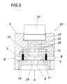
- Fig. 5 is a modification of the hydraulic valve 1 according to the invention Fig. 1 shown.
- the pilot valve 27 is fastened to the housing 2 via a threaded connection 23.
- the connecting lines 8 and 12 are provided in the housing 2, which provides a constructive simplicity.
- the connecting lines 8 and 12 connect to terminals 24 and 25 of the pilot valve 27, which can be connected via a displaceably mounted in the pilot valve 27 valve spool, which has not been shown in detail, to the output 26 of the pilot valve 27, as already FIG. 1 has been explained in detail.
- the output 26 of the pilot valve 27 is connected to the pressure chamber 10, so that the poppet valves 3 and 3 'can be actuated.
Landscapes
- Engineering & Computer Science (AREA)
- Physics & Mathematics (AREA)
- Fluid Mechanics (AREA)
- Mechanical Engineering (AREA)
- General Engineering & Computer Science (AREA)
- Multiple-Way Valves (AREA)
- Fluid-Driven Valves (AREA)
Applications Claiming Priority (1)
| Application Number | Priority Date | Filing Date | Title |
|---|---|---|---|
| AT6862009A AT508187B1 (de) | 2009-05-05 | 2009-05-05 | Hydraulikventil |
Publications (2)
| Publication Number | Publication Date |
|---|---|
| EP2249047A2 true EP2249047A2 (fr) | 2010-11-10 |
| EP2249047A3 EP2249047A3 (fr) | 2014-06-18 |
Family
ID=42576336
Family Applications (1)
| Application Number | Title | Priority Date | Filing Date |
|---|---|---|---|
| EP10450074.9A Withdrawn EP2249047A3 (fr) | 2009-05-05 | 2010-05-05 | Soupape hydraulique |
Country Status (2)
| Country | Link |
|---|---|
| EP (1) | EP2249047A3 (fr) |
| AT (1) | AT508187B1 (fr) |
Citations (3)
| Publication number | Priority date | Publication date | Assignee | Title |
|---|---|---|---|---|
| JPS6034583A (ja) | 1983-08-03 | 1985-02-22 | Toyooki Kogyo Co Ltd | パイロット操作切換弁 |
| US5398724A (en) | 1993-06-28 | 1995-03-21 | Woodward Governor Company | High speed electrically actuated gaseous fuel admission valve |
| WO2007088262A1 (fr) | 2006-01-30 | 2007-08-09 | Coval | Dispositif de commande d'un circuit consommateur de gaz comprime et generateur de vide faisant application |
Family Cites Families (3)
| Publication number | Priority date | Publication date | Assignee | Title |
|---|---|---|---|---|
| DE3838684C1 (en) * | 1988-11-15 | 1990-04-19 | Compart Kompressorenteile Gmbh & Co Kg, 2390 Flensburg, De | Valve, particularly for compressors or vacuum pumps |
| DE19525948A1 (de) * | 1995-07-17 | 1997-01-23 | Schaeffler Waelzlager Kg | Stufenventil |
| DE102006024183A1 (de) * | 2006-05-23 | 2007-11-29 | Robert Bosch Gmbh | Vorgesteuertes Ventil |
-
2009
- 2009-05-05 AT AT6862009A patent/AT508187B1/de not_active IP Right Cessation
-
2010
- 2010-05-05 EP EP10450074.9A patent/EP2249047A3/fr not_active Withdrawn
Patent Citations (3)
| Publication number | Priority date | Publication date | Assignee | Title |
|---|---|---|---|---|
| JPS6034583A (ja) | 1983-08-03 | 1985-02-22 | Toyooki Kogyo Co Ltd | パイロット操作切換弁 |
| US5398724A (en) | 1993-06-28 | 1995-03-21 | Woodward Governor Company | High speed electrically actuated gaseous fuel admission valve |
| WO2007088262A1 (fr) | 2006-01-30 | 2007-08-09 | Coval | Dispositif de commande d'un circuit consommateur de gaz comprime et generateur de vide faisant application |
Also Published As
| Publication number | Publication date |
|---|---|
| EP2249047A3 (fr) | 2014-06-18 |
| AT508187B1 (de) | 2011-01-15 |
| AT508187A1 (de) | 2010-11-15 |
Similar Documents
| Publication | Publication Date | Title |
|---|---|---|
| EP2382520B1 (fr) | Soupape de régulation de pression proportionnelle et son utilisation pour connection hydraulique | |
| DE3413866C2 (de) | Hydrostatisches Antriebssystem | |
| DE3114437C2 (de) | Druckregelventil | |
| DE3323363A1 (de) | Vorgesteuertes druckreduzierventil | |
| DE1576088B2 (de) | Schnellentlastungsventil fuer hydraulische kraftzylinder | |
| DE102014017801A1 (de) | Druckbegrenzungsventil | |
| DE4307990A1 (de) | Hydraulisches Steuerventil | |
| EP2642132B1 (fr) | Agencement de soupape hydraulique avec un agencement de soupape pilote hydraulique | |
| EP1078167B1 (fr) | Microsoupape | |
| WO2000034664A1 (fr) | Clapet de non retour pilote destine a un systeme de portes pressions | |
| DE2156696C2 (de) | Steuervorrichtung mit einer Meßspindel und einem Mitlaufteil | |
| EP1884692A1 (fr) | Soupape pneumatique à retour rapide | |
| DE2712491C2 (de) | Elektromagnetisch betätigtes, druckgesteuertes Ventil | |
| DE19632368A1 (de) | Elektrohydraulisches Regelwegeventil | |
| AT508187B1 (de) | Hydraulikventil | |
| EP0687818A1 (fr) | Valve pneumatique | |
| WO2006133797A1 (fr) | Unite de blocage a actionnement hydraulique et axe de regulation hydraulique comportant une telle unite | |
| DE19932139B4 (de) | Vorgesteuertes Schieberventil | |
| DE102020113290B4 (de) | Ventil mit einem Rückflussverhinderer | |
| DE102014207393B4 (de) | Ventil | |
| EP2337980B1 (fr) | Distributeur | |
| DE19923345A1 (de) | Elektrohydraulische Steuereinrichtung | |
| DE2602328C3 (de) | Drosselventil | |
| DE102014007475A1 (de) | Ventilanordnung zur gesteuerten Druckentlastung fluidgefüllter Leitungen unter erhöhten Sicherheitsanforderungen | |
| EP2778437B1 (fr) | Soupape hydraulique |
Legal Events
| Date | Code | Title | Description |
|---|---|---|---|
| PUAI | Public reference made under article 153(3) epc to a published international application that has entered the european phase |
Free format text: ORIGINAL CODE: 0009012 |
|
| AK | Designated contracting states |
Kind code of ref document: A2 Designated state(s): AL AT BE BG CH CY CZ DE DK EE ES FI FR GB GR HR HU IE IS IT LI LT LU LV MC MK MT NL NO PL PT RO SE SI SK SM TR |
|
| AX | Request for extension of the european patent |
Extension state: BA ME RS |
|
| PUAL | Search report despatched |
Free format text: ORIGINAL CODE: 0009013 |
|
| AK | Designated contracting states |
Kind code of ref document: A3 Designated state(s): AL AT BE BG CH CY CZ DE DK EE ES FI FR GB GR HR HU IE IS IT LI LT LU LV MC MK MT NL NO PL PT RO SE SI SK SM TR |
|
| AX | Request for extension of the european patent |
Extension state: BA ME RS |
|
| RIC1 | Information provided on ipc code assigned before grant |
Ipc: F15B 13/04 20060101AFI20140515BHEP |
|
| 17P | Request for examination filed |
Effective date: 20141218 |
|
| RBV | Designated contracting states (corrected) |
Designated state(s): AL AT BE BG CH CY CZ DE DK EE ES FI FR GB GR HR HU IE IS IT LI LT LU LV MC MK MT NL NO PL PT RO SE SI SK SM TR |
|
| GRAP | Despatch of communication of intention to grant a patent |
Free format text: ORIGINAL CODE: EPIDOSNIGR1 |
|
| INTG | Intention to grant announced |
Effective date: 20170119 |
|
| STAA | Information on the status of an ep patent application or granted ep patent |
Free format text: STATUS: THE APPLICATION IS DEEMED TO BE WITHDRAWN |
|
| 18D | Application deemed to be withdrawn |
Effective date: 20170530 |