EP2248732B1 - Closure body - Google Patents
Closure body Download PDFInfo
- Publication number
- EP2248732B1 EP2248732B1 EP09252748A EP09252748A EP2248732B1 EP 2248732 B1 EP2248732 B1 EP 2248732B1 EP 09252748 A EP09252748 A EP 09252748A EP 09252748 A EP09252748 A EP 09252748A EP 2248732 B1 EP2248732 B1 EP 2248732B1
- Authority
- EP
- European Patent Office
- Prior art keywords
- closure
- closure body
- spout
- venting
- closure assembly
- Prior art date
- Legal status (The legal status is an assumption and is not a legal conclusion. Google has not performed a legal analysis and makes no representation as to the accuracy of the status listed.)
- Active
Links
Images


Classifications
-
- B—PERFORMING OPERATIONS; TRANSPORTING
- B65—CONVEYING; PACKING; STORING; HANDLING THIN OR FILAMENTARY MATERIAL
- B65D—CONTAINERS FOR STORAGE OR TRANSPORT OF ARTICLES OR MATERIALS, e.g. BAGS, BARRELS, BOTTLES, BOXES, CANS, CARTONS, CRATES, DRUMS, JARS, TANKS, HOPPERS, FORWARDING CONTAINERS; ACCESSORIES, CLOSURES, OR FITTINGS THEREFOR; PACKAGING ELEMENTS; PACKAGES
- B65D47/00—Closures with filling and discharging, or with discharging, devices
- B65D47/04—Closures with discharging devices other than pumps
- B65D47/06—Closures with discharging devices other than pumps with pouring spouts or tubes; with discharge nozzles or passages
- B65D47/061—Closures with discharging devices other than pumps with pouring spouts or tubes; with discharge nozzles or passages with telescopic, retractable or reversible spouts, tubes or nozzles
- B65D47/063—Closures with discharging devices other than pumps with pouring spouts or tubes; with discharge nozzles or passages with telescopic, retractable or reversible spouts, tubes or nozzles with flexible parts
-
- B—PERFORMING OPERATIONS; TRANSPORTING
- B65—CONVEYING; PACKING; STORING; HANDLING THIN OR FILAMENTARY MATERIAL
- B65D—CONTAINERS FOR STORAGE OR TRANSPORT OF ARTICLES OR MATERIALS, e.g. BAGS, BARRELS, BOTTLES, BOXES, CANS, CARTONS, CRATES, DRUMS, JARS, TANKS, HOPPERS, FORWARDING CONTAINERS; ACCESSORIES, CLOSURES, OR FITTINGS THEREFOR; PACKAGING ELEMENTS; PACKAGES
- B65D25/00—Details of other kinds or types of rigid or semi-rigid containers
- B65D25/38—Devices for discharging contents
- B65D25/40—Nozzles or spouts
- B65D25/42—Integral or attached nozzles or spouts
- B65D25/44—Telescopic or retractable nozzles or spouts
-
- B—PERFORMING OPERATIONS; TRANSPORTING
- B65—CONVEYING; PACKING; STORING; HANDLING THIN OR FILAMENTARY MATERIAL
- B65D—CONTAINERS FOR STORAGE OR TRANSPORT OF ARTICLES OR MATERIALS, e.g. BAGS, BARRELS, BOTTLES, BOXES, CANS, CARTONS, CRATES, DRUMS, JARS, TANKS, HOPPERS, FORWARDING CONTAINERS; ACCESSORIES, CLOSURES, OR FITTINGS THEREFOR; PACKAGING ELEMENTS; PACKAGES
- B65D47/00—Closures with filling and discharging, or with discharging, devices
- B65D47/04—Closures with discharging devices other than pumps
- B65D47/06—Closures with discharging devices other than pumps with pouring spouts or tubes; with discharge nozzles or passages
- B65D47/10—Closures with discharging devices other than pumps with pouring spouts or tubes; with discharge nozzles or passages having frangible closures
- B65D47/103—Membranes with a tearing element
-
- B—PERFORMING OPERATIONS; TRANSPORTING
- B65—CONVEYING; PACKING; STORING; HANDLING THIN OR FILAMENTARY MATERIAL
- B65D—CONTAINERS FOR STORAGE OR TRANSPORT OF ARTICLES OR MATERIALS, e.g. BAGS, BARRELS, BOTTLES, BOXES, CANS, CARTONS, CRATES, DRUMS, JARS, TANKS, HOPPERS, FORWARDING CONTAINERS; ACCESSORIES, CLOSURES, OR FITTINGS THEREFOR; PACKAGING ELEMENTS; PACKAGES
- B65D47/00—Closures with filling and discharging, or with discharging, devices
- B65D47/04—Closures with discharging devices other than pumps
- B65D47/06—Closures with discharging devices other than pumps with pouring spouts or tubes; with discharge nozzles or passages
- B65D47/12—Closures with discharging devices other than pumps with pouring spouts or tubes; with discharge nozzles or passages having removable closures
- B65D47/122—Threaded caps
- B65D47/123—Threaded caps with internal parts
-
- B—PERFORMING OPERATIONS; TRANSPORTING
- B65—CONVEYING; PACKING; STORING; HANDLING THIN OR FILAMENTARY MATERIAL
- B65D—CONTAINERS FOR STORAGE OR TRANSPORT OF ARTICLES OR MATERIALS, e.g. BAGS, BARRELS, BOTTLES, BOXES, CANS, CARTONS, CRATES, DRUMS, JARS, TANKS, HOPPERS, FORWARDING CONTAINERS; ACCESSORIES, CLOSURES, OR FITTINGS THEREFOR; PACKAGING ELEMENTS; PACKAGES
- B65D2401/00—Tamper-indicating means
- B65D2401/15—Tearable part of the closure
Definitions
- the invention relates to a closure body in accordance with the preamble of appended claim 1.
- the present disclosure relates to the use of memory band portions and using one or more in combination with venting ears that change orientation as the spout is extended.
- memory band refers to the addition of a thicker material section to the wall of the spout such that the spout can be deflected and then set and retained in a desired orientation. Further disclosed features include the shape and styling of the threaded closing cap.
- Container closures and closure assemblies of the type generally described herein often include some tamper-evident feature incorporating a plurality of frangible elements.
- One such product has been offered by Rieke Corporation of Auburn. Indiana, under its FLEXSPOUT ® trademark.
- This product includes a tamper-evident closing cap and a closure body with a nestable and extendable spout.
- a tamper-evident closing cap threads onto the threaded end of the spout and the cap must be removed in order to gain access to the contents of the container (drum) via the interior of the spout.
- the closure body is received by a raised surrounding (annular) wall that defines the container opening and when used on a metal drum end, the closure includes an annular retaining member that fits over an outer wall portion of the closure body and, by crimping, secures the outer wall portion to the surrounding wall which defines the container opening.
- the closure assembly construction further includes a series of frangible elements that connect a pair of bail handles that are used to extend the spout with the remainder of the closing cap.
- one style of tamper-evident cap When a plastic drum or container receives a FLEXSPOUT ® closure, one style of tamper-evident cap includes an outer annular portion that snaps over an outer wall portion of the closure body and secures the outer wall portion to the surrounding wall that defines the container opening.
- a series of frangible elements connects the outer annular portion of the tamper-evident cap with the remainder of the cap body, principally with a pair of bail handles which are used to extend the spout.
- venting ears Although not the focus of the claimed invention, one structural feature or characteristic that has been used with closures and closure assemblies of the general style being discussed herein is the use of a series of venting ears or venting tabs.
- One such example is disclosed in U.S. Patent No. 4,618,078, issued October 21, 1986 to Hamman, et al.
- a venting capability can also be provided by the use of an annular cup with a series of spaced-apart openings or slits.
- a still further style uses an annular ring with edge openings that extend below the spout.
- these venting ears may also be referred to as venting tabs.
- the focus of this disclosure is on the use of the memory band portions.
- the addition of a thicker section of material as part of the extendable spout provides a "memory band” feature for the spout.
- This "memory band” structure allows the extended spout to be flexed or bent in a desired direction and then stay there, in that selected orientation, until moved manually, to a new orientation.
- a vented closure see U.S. Patent No. 4,618,078, issued October 21, 1986 to Hamman et al. as one example of a vented closure, the flexing or bending of the spout in a desired direction provides an added benefit.
- the bending or flexing of the spout into the desired direction for discharge of the contents of the container puts into play only those venting ears that are advantageous to the actual dispensing and takes the other venting ears out of play. This in turn yields a larger dispensing opening and therefore a faster flow rate for the outflow or dispensing of product from the container.
- the outflow of fluid product from the drum or container is still smoother (as compared to a non-vented closure) due to the fact that some of the venting ears are still used.
- the venting ears which are in play when the extended spout is flexed provide an adequate path and sufficient flow area for air based upon the exiting flow rate.
- the memory band is located adjacent the venting ears.
- the present disclosure incorporates a design change to an earlier closure style which included a single memory band adjacent the raised outlet opening of the container.
- the present disclosure also describes a plurality of venting ears wherein the width of each venting ear is less (i.e., more narrow) as compared to prior venting ears and the number of venting ears is increased compared to prior venting ears.
- each venting ear is also a consideration relative to its point of joinder to the closure body and the flow opening to be defined by the inner ends or edges of each venting ear once the spout is extended.
- the focus of the claimed invention is directed to the memory band feature.
- the invention is defined by a closure body as defined by appended claim 1.
- the memory band portion being constructed and arranged for enabling the generally cylindrical section to maintain a selected orientation upon deflecting into a selected orientation for directional discharge of container contents.
- One object of the present disclosure is to provide an improved vented closure assembly for a container.
- FIGS. 1-7 there is illustrated a generic closure assembly 20.
- Closure assembly 20 is constructed and arranged for secure connection to or into an outlet opening defining structure whether a raised annular outlet wall or a container opening edge or some other opening configuration.
- the defined outlet opening is positioned within the end panel 19b of a corresponding container or drum 19.
- the upper surface 19a of the end panel 19b of container 19 is planar and surrounds the raised annular outlet wall or container opening, depending on the particular construction.
- the raised outlet wall defining the outlet opening of a metal drum end is illustrated in FIG. 4 .
- the closure assembly 20 can also be used with a plastic drum or pail.
- FIGS. 1-3 show the form of closure assembly 20 as it would be sold to a drum or pail manufacturer or filler.
- FIG. 4 illustrates the manner of attaching the closure assembly 20 to the raised opening of a container or drum 19.
- the removable (pull to tear out) diaphragm see FIG. 5 ) has been removed.
- the extended orientation of FIGS. 6 and 7 shows the undeflected form of the spout and the relationship of the venting ears to each other prior to any deflection of the spout.
- FIGS. 1-7 depict what has been described as a "generic" closure assembly 20 While the present disclosure is directed to three embodiments for the closure assembly, the general construction and appearance, components parts, and initial movement to the extended orientation of all three embodiments, as disclosed herein, are essentially the same. The differences between these three embodiments are limited to the number and location of a thicker spout wall portion or section that provides a unique spout deflection capability. These differences between the three embodiments will be described and explained relative to FIGS. 8A-10B . First though, the details of the (generic) closure assembly 20 will be described.
- closure assembly 20 includes a closure body 22, tamper-evident closing cap 23, and annular metal retainer 24.
- Each of these three component parts constitutes a unitary component with the closure body 22 being molded out of plastic, the tamper-evident closing cap 23 being molded out of plastic, and the retainer 24 being formed as a unitary component out of metal.
- the details of the closure body 22 are illustrated in FIGS. 6 and 7 . Some of the structural details of the closing cap 23 and retainer 24 are further described in U.S. Application Serial No. 11/423,630, Filed June 12, 2006 , entitled A CLOSURE ASSEMBLY HAVING A SPOUT WITH A MEMORY BAND FOR SPOUT DIRECTING.
- closing cap design changes made to closing cap 23 which are not part of the closing cap disclosed in the '630 application.
- the closure assembly 20 is constructed and arranged to be preassembled, as illustrated, and then applied to the raised outlet wall of the container end panel 19b for crimping of the retainer 24 so as to anchor the closure body 22 to the outlet wall.
- closure assembly 20 assembles onto the formed and raised outlet wall 27 that defines outlet opening 21.
- the closure body 22 includes an annular outlet lip 28 formed with an inverted annular channel 29.
- the annular channel 29 fits over and around outlet wall 27, see FIGS. 4 and 6 .
- the tamper-evident closing cap 23 is internally threaded and the dispensing end 30 of the nestable and extendable spout 31 of closure body 22 is externally threaded for receipt of the closing cap 23.
- the closing cap 23 can be threaded onto spout 31 either before or after the closure body is crimped onto outlet wall 27 by the use of metal retainer 24.
- the metal retainer 24 would be preassembled onto the closure body 22, see FIGS. 1 and 2 .
- Closure body 22 includes a transition region 38 with an invertible fold 48 that reverses its orientation when changing the closure body from a nested orientation (see FIG. 1 ) to an extended orientation (see FIGS. 6 and 7 ).
- Closure body 22 also includes a tear-out diaphragm 49 with a unitary pull ring 50.
- a weakened annular score line or an annular severable membrane surrounds the diaphragm 49 and connects the outer edge of the diaphragm to the inner surface of the spout 31.
- the pull ring 50 is joined to one edge portion of diaphragm 49 and by pulling upwardly on ring 50, the diaphragm 49 is able to be torn out of the interior of spout 31.
- the unitary molding of closure assembly 20 includes the unitary construction of pull ring 50 and diaphragm 49.
- the spout 31 can be considered as having three sections or portions including an inner, generally cylindrical section 53, an outer, frustoconical section 54, and a transition region or portion 38 therebetween.
- the transition region 38 includes the invertible fold 48.
- the cooperating frustoconical section 54 includes a series of venting ears 57 that are positioned at fold 58 and arranged in an annular array, substantially equally spaced apart. Each venting ear depends in an axially downward direction when the closure body 22 is in its nested orientation. When the closure body 22, specifically the spout 31, is extended, the fold 58 moves and flips the venting ears 57 into a lateral or generally horizontal orientation, see FIGS. 6 and 7 .
- FIGS. 1, 2 , 4 and 6 represent the typical, upright orientation and centerline 59 represents the longitudinal axis through the geometric center of the closure assembly 20.
- an axial direction is generally parallel to centerline 59 and a lateral direction is generally perpendicular to centerline 59.
- Closing cap 23 includes, as part of its unitary, molded plastic construction, a pair of oppositely-disposed bail handles 44 and 45. Each bail handle 44 and 45 is joined to the remainder of the closing cap 23 by living hinges. As initially configured, prior to any opening of the closure assembly, the bail handles 44 and 45 lay substantially flat (planar) and the geometric plane in which they lay is substantially parallel with the planar upper surface 19a of the container end. In use, whether or not the bail handles 44 and 45 are each secured in a down and flush orientation by a frangible element, the living hinge and the initially molded condition positions the bail handles down and generally flush with the upper surface of the tamper-evident closing cap 23.
- the planar orientation of the two bail handles positions them in a geometric plane that is substantially parallel with upper surface 19a.
- the living hinges experience a slight plastic deformation. This causes the bail handles 44 and 45 to remain slightly raised after the initial lifting.
- Closing cap 23 includes a low-profile, substantially planar upper lip 23a which comprises the top panel 23b of the threaded cap body 23c and includes bail handles 44 and 45, living hinge portions 46 and 47, a pair of lift tabs 23d, and the referenced frangible elements 23e.
- the two living hinge portions 46 and 47 are generally spaced 180 degrees apart.
- the two lift tabs 23d are also generally spaced 180 degrees apart and are further spaced generally equidistant (circumferentially) from the hinge portions.
- One frangible element 23e is positioned between each hinge portion - lift tab pair.
- This clearance space 24a has a substantially uniform spacing and provides access to the underside of each lift tab 23d (typically with a fingertip/nail of the user) so as to begin the process of lifting each bail handle 44 and 45.
- the outermost edge 23f of each lift tab 23d is slightly spaced from the inner, generally circular edge of retainer 24 to further facilitate the process of lifting each bail handle 44 and 45.
- This low-profile cap construction and the lift tab construction create an aesthetically clean, trim, and sleek appearance for closing cap 23.
- the clearance spaces and separation as described above of the closure cap relative to retainer 24 enable the user to readily and easily gain access to the underside of each lift tab for beginning the lifting of each bail handle.
- This initial bail handle lifting is what causes the frangible elements 23e to fracture.
- the bail handles can be lifted to a higher elevation pivoting about the two living hinge portions 46 and 47 so as to permit a more complete grasping by the hand/fingers of the user so as to lift the spout to an extended orientation.
- closure assembly 20 is intended to represent a generic form of closure assembly as a way to describe the basic construction of the closure body 22, closing cap 23, and retainer 24.
- closure assemblies 120, 220, and 320 differ from one another in the number and location of thicker wall sections or portions (memory bands) that provide a suitable structure for deflection of the spout and for retaining the deflected spout in the desired or selected orientation.
- thicker wall sections or portions are also referenced herein as thicker bands or "memory band” portions. This terminology comes from the branding used for the product source of origin. This product branding uses the trademark phrase "MEMORY BAND".
- closure assembly 120 includes a single thicker wall portion identified as band 122 that is located at or at least adjacent fold 58 and generally coincides with the location where the venting ears 57 are positioned.
- Closure assembly 220 includes a second thicker wall portion identified as band 222 that is located at or at least closely adjacent to invertible fold 48.
- Band 222 is essentially of the same construction as band 122.
- Closure assembly 220 thus includes two thicker wall portions or bands 122 and 222 that are spaced-apart from each other. Each thicker wall portion or band 122 and 222 is annular in shape, consistent with the annular form and shaping of the entire closure assembly.
- Closure assembly 320 includes a single thicker wall portion identified as band 322 that is located in a different location than the single band 122 of closure assembly 120.
- Band 3222 is essentially the same as band 222 in construction and location. The geometry, contours, and dimensions of each thicker wall portion are illustrated in FIG. 12 .
- the wall thickness of the cooperating frustoconical section 54 is substantially uniform until reaching the vicinity of point A.
- Portion 100 begins at this location and the wall thickness increases.
- Point A also signifies the start of bend 58.
- the width of portion 100 gradually increases until point C is reached and the width is generally uniform between points C and D. From point D to point B the thickness gradually decreases.
- Thickness dimension d1 is approximately 0.025 inches (0.635 mm) at the bend (Point A).
- Thickness dimension d2 is approximately 0.041 inches (1.041 mm) between Points C and D.
- Length dimension d3 is approximately 0.075 inches (1.905 mm).
- Thickness dimension d4 at Point B is approximately 0.023 inches (0.584 mm).
- Angle a1 measures approximately 30 degrees.
- Point A generally coincides with a concave bend in the cooperating frustoconical section 54 or at least the start of the bend, as viewed from the exterior of the closure body 22.
- Point B generally coincides with a convex bend in the cooperating frustoconical section 54.
- closure assembly 120 is described in greater detail.
- the area or portion of the frustoconical section 54 that has been referenced as fold 58 has a thicker wall for that portion 122 generally between points A and B.
- This thicker wall portion or band 122 by design, generally coincides with the location where the venting ears 57 are positioned.
- the wall thickness of band 122 is approximately twice the wall thickness of the spout portions adjacent to band 122.
- Band 122 permits the extended spout 31 to be flexed so as to point it in a desired dispensing direction and generally remain in that selected orientation.
- the principle of the mechanism is similar to a flexible drinking straw, such as those straws used in hospitals.
- the thicker band 122 offsets stresses in the frustoconical section 54 which typically cause a symmetric extended condition. This off-setting or overriding is caused by the material strength of thicker band 122 and the adjacent material or spout body material "break-over" into a lower stress condition similar to a spiral twisted annular belt or "rubber band".
- the band has a near neutral stress condition when the spout is extended axially.
- a higher unstable stress condition exists in the band and adjacent areas.
- This condition is a three dimensional stress condition similar to common two dimensional self-closing plastic hinge designs which orient in either the open or closed position and will not maintain or stabilize in a partially open or closed position.
- the reference to “deflection” means that the spout or the portion or section of the spout that is being deflected into a desired or selected dispensing orientation will generally stay in that orientation until moved manually to another orientation.
- the branding terminology that has been adopted for the thicker wall portion 76 is "memory band”. The “deflection” moves the axial centerline of the spout from a generally vertical orientation into something which is off of vertical.
- FIGS. 8A, 8B and 11 When the spout 31 is flexed in a direction to achieve a desired orientation, see FIGS. 8A, 8B and 11 , some of the venting ears 57, specifically those closest to the direction of flexing, move from horizontal in the direction of vertical, but do not achieve a complete vertical orientation. The extent or degree of travel towards the vertical orientation is controlled by the amount or degree of flexing of spout 31, pivoting at thicker wall portion 122. As some of the venting ears pivot back towards vertical, the size and shape of central flow opening 77 changes. The cross sectional area increases and the generally circular shape becomes more oval, though only slightly, see FIG. 8B .
- vent opening 78 on the side with the deflected venting ears opens up, but pouring from that side does not require venting. Before dispensing could occur from any direction and thus vent openings had to be provided around the entire central flow opening 77. Now that the flow is directional, only vent openings on the opposite or top side are required for "anti-glug" dispensing.
- vent openings 78 are provided above the exiting flow, i.e., on the opposite side of the spout 31, the dispensing flow will not glug. While all of the benefits of using a closure assembly with venting ears are still achieved by the present invention, the added benefit of smoother and faster exiting (i.e., dispensing) flow is provided by manipulation of the venting ears and having a central flow opening with a larger cross sectional area.
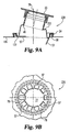
- FIGS. 9A, 9B , 10A, and 10B are essentially the same as closure assembly 120 in terms of the use of venting ears 57.
- the intended differences for these three closure assemblies 120, 220, and 320 are limited to the number of thicker bands being used and where those thicker bands are positioned.
- FIGS. 10A and 10B there is no venting ear 57 movement due to the deflection of the spout.
- This difference in terms of the lack of movement of venting ears 57 is due to the fact that closure assembly 320 does not have a thicker band positioned at the fold 58 location. Accordingly, as the spout is deflected about invertible fold 48, any effects on venting ears 57 located at fold 58 are negligible.
- venting ears 57 in the nested orientation of spout 29 (as a generic representation) reveals that each venting ear 57 extends in a downward or depending direction with a noticeable clearance space 90 between adjacent venting ears 57.
- Each clearance space 90 has a slight upward taper due to the slight downward taper of each venting ear 57.
- Each clearance space 90 is substantially the same and results automatically based on the width and shaping of each venting ear 57 and the number of venting ears selected. The width of each venting ear and the number of ears cooperate so as to preclude any "noticeable contact" between adjacent venting ears when the corresponding spout is extended.
- noticeable contact means contact between adjacent venting ears which is designed to occur based on the number and size of the venting ears 57. Typical of prior art structures, the venting ear corners overlap, by design. With the present disclosure, such contact is designed not to occur and thus, when the spout is extended, there is no noticeable contact between adjacent venting ears 57. Since the spout is molded from plastic and since there is some degree of flexibility, manual alteration or reshaping could cause the edges of adjacent venting ears to perhaps touch slightly. This touching contact is not considered to be “noticeable”.
- Each venting ear 57 has a polyethylene body and is unitarily molded as part of each closure body.
- the base 91 of each venting ear is joined with the closure body at the location of fold 58.
- the venting ears initially flip to a generally horizontal orientation.
- the radiating pattern as illustrated in FIG. 7 shows that the inner edges 92 define an inner opening 77 for flow exit of the container contents.
- the spaces 90 between adjacent venting ears 57 provide the venting capability for the inflow of air as vent opening 78.
- each venting ear is approximately 0.05 inches (1.270 mm) thick, approximately 0.36 inches (9.144 mm) wide (at its widest point), and approximately 0.48 inches (12.192 mm) long.
- venting ears used for a closure assembly that is designed for a standard 23 ⁇ 8 inch (63 mm) opening.
- the length, width, and number of venting ears have to be considered so that there will be some degree of definition to the flow opening, venting passageways, and the avoidance of any noticeable contact between adjacent venting ears. If the number of venting ears is too few, based on a selected width, then the flow opening will not be well defined. Increasing the length of each venting ear would help to some extent, but this could result in a well-defined flow opening that is too small for effective discharge of the container contents.
Landscapes
- Engineering & Computer Science (AREA)
- Mechanical Engineering (AREA)
- Closures For Containers (AREA)
- Glass Compositions (AREA)
- Temperature-Responsive Valves (AREA)
- Materials For Medical Uses (AREA)
Priority Applications (1)
| Application Number | Priority Date | Filing Date | Title |
|---|---|---|---|
| PL09252748T PL2248732T3 (pl) | 2009-05-07 | 2009-12-08 | Korpus zamknięcia |
Applications Claiming Priority (2)
| Application Number | Priority Date | Filing Date | Title |
|---|---|---|---|
| US17621309P | 2009-05-07 | 2009-05-07 | |
| US12/611,211 US8292133B2 (en) | 2009-05-07 | 2009-11-03 | Vented closure assembly for a container |
Publications (2)
| Publication Number | Publication Date |
|---|---|
| EP2248732A1 EP2248732A1 (en) | 2010-11-10 |
| EP2248732B1 true EP2248732B1 (en) | 2012-02-08 |
Family
ID=42289308
Family Applications (1)
| Application Number | Title | Priority Date | Filing Date |
|---|---|---|---|
| EP09252748A Active EP2248732B1 (en) | 2009-05-07 | 2009-12-08 | Closure body |
Country Status (11)
| Country | Link |
|---|---|
| US (1) | US8292133B2 (pl) |
| EP (1) | EP2248732B1 (pl) |
| AT (1) | ATE544688T1 (pl) |
| AU (1) | AU2009243533B2 (pl) |
| BR (1) | BRPI0905242A2 (pl) |
| CA (1) | CA2686804C (pl) |
| DK (1) | DK2248732T3 (pl) |
| ES (1) | ES2381067T3 (pl) |
| MX (1) | MX2009013630A (pl) |
| PL (1) | PL2248732T3 (pl) |
| PT (1) | PT2248732E (pl) |
Families Citing this family (29)
| Publication number | Priority date | Publication date | Assignee | Title |
|---|---|---|---|---|
| USD641628S1 (en) * | 2010-11-17 | 2011-07-19 | Rieke Corporation | Closure for a container |
| CN103287699B (zh) * | 2013-06-04 | 2015-04-22 | 余伟文 | 一种油漆桶 |
| CN104724366A (zh) * | 2013-06-04 | 2015-06-24 | 余伟文 | 一种油漆桶的油嘴 |
| TWD169385S (zh) | 2013-10-31 | 2015-08-01 | 科萊恩製造(法國)公司 | 容器之部分(一) |
| USD761103S1 (en) | 2013-11-07 | 2016-07-12 | Clariant Production (France) Sas | Container |
| USD783400S1 (en) | 2014-03-21 | 2017-04-11 | Clariant Production (France) Sas | Closure for container |
| USD766716S1 (en) | 2014-04-30 | 2016-09-20 | Clariant Production (France) Sas | Container |
| USD769719S1 (en) | 2014-05-06 | 2016-10-25 | Clariant Production (France) Sas | Container |
| USD791586S1 (en) | 2014-06-17 | 2017-07-11 | Clariant Production (France) Sas | Container |
| US9669972B2 (en) * | 2014-10-09 | 2017-06-06 | Container Packaging Systems, Inc. | Anti-glug device for liquid containers and pour spouts |
| USD793235S1 (en) | 2014-11-27 | 2017-08-01 | Clariant Production (France) Sas | Container |
| USD766080S1 (en) | 2015-02-26 | 2016-09-13 | Clariant Production (France) Sas | Container |
| US10093460B2 (en) | 2015-08-14 | 2018-10-09 | Yeti Coolers, Llc | Container with magnetic cap |
| USD787893S1 (en) | 2015-11-20 | 2017-05-30 | Yeti Coolers, Llc | Jug |
| US10959552B2 (en) | 2016-10-17 | 2021-03-30 | Yeti Coolers, Llc | Container and method of forming a container |
| EP3632274B1 (en) | 2016-10-17 | 2021-05-12 | Yeti Coolers, LLC | Container and method of forming a container |
| US10959553B2 (en) | 2016-10-17 | 2021-03-30 | Yeti Coolers, Llc | Container and method of forming a container |
| US11034505B2 (en) | 2016-10-17 | 2021-06-15 | Yeti Coolers, Llc | Container and method of forming a container |
| USD860716S1 (en) | 2017-03-27 | 2019-09-24 | Yeti Coolers, Llc | Container lid |
| USD857497S1 (en) | 2018-02-22 | 2019-08-27 | Stolle Machinery Company, Llc | Push button closure |
| CN108996005A (zh) * | 2018-07-27 | 2018-12-14 | 张艳丽 | 一种塑料桶桶盖 |
| USD896572S1 (en) | 2018-08-20 | 2020-09-22 | Yeti Coolers, Llc | Container lid |
| USD883737S1 (en) | 2018-10-17 | 2020-05-12 | Yeti Coolers, Llc | Lid |
| USD897151S1 (en) | 2018-10-17 | 2020-09-29 | Yeti Coolers, Llc | Lid |
| USD871133S1 (en) | 2018-10-17 | 2019-12-31 | Yeti Coolers, Llc | Lid |
| USD883738S1 (en) | 2018-10-17 | 2020-05-12 | Yeti Coolers, Llc | Lid |
| US11396408B2 (en) | 2019-08-05 | 2022-07-26 | Yeti Coolers, Llc | Lid for container |
| US12151859B2 (en) * | 2019-08-29 | 2024-11-26 | Rieke Llc | Child resistant closure and spout combination |
| EP4518980A1 (en) | 2022-05-04 | 2025-03-12 | Rieke LLC | Container and closure systems with flame mitigation |
Family Cites Families (43)
| Publication number | Priority date | Publication date | Assignee | Title |
|---|---|---|---|---|
| US2561596A (en) * | 1947-06-05 | 1951-07-24 | Rieke Metal Products Corp | Container nestable and contractible pouring spout |
| US2898018A (en) * | 1955-10-26 | 1959-08-04 | John E Borah | Container spout |
| US3604740A (en) * | 1969-02-04 | 1971-09-14 | Rieke Corp | Container closure combination |
| US3613966A (en) * | 1969-04-17 | 1971-10-19 | Rieke Corp | Nestable pouring spout with wall-supporting cap |
| FR2142571A1 (pl) * | 1971-06-21 | 1973-02-02 | Rieke Corp | |
| US4236629A (en) * | 1978-10-02 | 1980-12-02 | American Flange & Manufacturing Co. Inc. | Nestable pouring spout assembly |
| SE8003125L (sv) | 1979-07-26 | 1981-01-27 | Amsted Ind Inc | Anordning for boggi hos jernvegsvagn |
| US4294382A (en) * | 1979-07-26 | 1981-10-13 | Riche Corporation | Container closure device |
| US4320861A (en) * | 1980-05-12 | 1982-03-23 | Rieke Corporation | Molded plastic tamper-proof cap with pull ring and tearable membranes |
| CA1215944A (en) | 1982-06-03 | 1986-12-30 | Hugo Mueller | Nestable self-vent spout |
| US4568006A (en) * | 1982-06-03 | 1986-02-04 | American Flange & Manufacturing Co. Inc. | Nestable self-venting spout |
| US4632282A (en) * | 1984-03-02 | 1986-12-30 | Hirohisa Nagashima | Spout assembly |
| US4555048A (en) * | 1984-05-16 | 1985-11-26 | Rieke Corporation | Vented nestable pouring spout |
| US4618078A (en) | 1984-05-16 | 1986-10-21 | Rieke Corporation | Vented nestable pouring spout |
| FR2578819B1 (fr) | 1985-03-14 | 1987-12-04 | Rical Sa | Verseur orientable pour bidons et recipients analogues |
| DE3539405A1 (de) | 1985-11-07 | 1987-05-14 | Berg Jacob Gmbh Co Kg | Gegen aeussere eingriffe gesicherte verschlussvorrichtung eines behaelters |
| US4699290A (en) * | 1986-06-18 | 1987-10-13 | Adams Jay J | Sanitary tamperproof double closure container end cap |
| US4718553A (en) * | 1987-02-11 | 1988-01-12 | Ivy Hill Corporation | Tamper-evident packaging, method of making same, and intermediate therein |
| US4801031A (en) * | 1987-05-28 | 1989-01-31 | Owens-Illinois Closure Inc. | Tamper-indicating closures and packages |
| DE3805648A1 (de) | 1988-02-24 | 1989-09-07 | Berg Jacob Gmbh Co Kg | Ausziehbarer ausgiessverschluss |
| US4805791A (en) * | 1988-05-04 | 1989-02-21 | Continental White Cap, Inc. | Band with lock ring for tamper-evident cap |
| US4877143A (en) * | 1988-06-16 | 1989-10-31 | Travisano Frank P | Tamper evident indicating means |
| FR2642046B1 (fr) * | 1989-01-23 | 1991-04-05 | Astra Plastique | Tube verseur escamotable a orientation multidirectionnelle |
| US4921147A (en) * | 1989-02-06 | 1990-05-01 | Michel Poirier | Pouring spout |
| FR2655620B1 (fr) | 1989-12-08 | 1992-01-17 | Astra Plastique | Capsule de bouchage a vis, a bande d'inviolabilite. |
| US4981230A (en) * | 1990-03-15 | 1991-01-01 | Continental White Cap, Inc. | Composite cap including tamper indicating band |
| US5035341A (en) * | 1990-10-31 | 1991-07-30 | Continental White Cap, Inc. | Closure cap having tamper indicating means |
| US5230442A (en) * | 1992-09-03 | 1993-07-27 | Dean Jr Garland E | Oil spout and container assembly |
| GB9322113D0 (en) * | 1993-10-27 | 1993-12-15 | Sturk Ron | Closure for containers |
| US5641099A (en) * | 1995-12-08 | 1997-06-24 | Rieke Corporation | Nestable pouring spout assembly |
| US5722570A (en) * | 1996-06-14 | 1998-03-03 | Sultzer, Iii; Harry D. | Container with extendable, directable pouring spout |
| US6000570A (en) * | 1997-05-01 | 1999-12-14 | Nelson; James L. | Container lid with tamper evident slip band |
| US5967376A (en) * | 1997-08-05 | 1999-10-19 | Rieke Corporation | Insert molded tamper evident pouring spout |
| AU745180B2 (en) | 1998-12-07 | 2002-03-14 | Tjandra Limanjaya | Closure cap |
| AU1542500A (en) * | 1998-12-10 | 2000-06-26 | Ron Sturk | Flow vented and pressure vented closures |
| US6135985A (en) * | 1999-04-07 | 2000-10-24 | Fromer; Mark D. | Dispenser arrangement for dispensing eyedrops |
| US6386405B1 (en) | 2000-12-18 | 2002-05-14 | Royal Packaging Industries Van Leer Nv | Snap on closure and method |
| ITMI20010533A1 (it) * | 2001-03-13 | 2002-09-13 | Inge Spa | Flacone per l'erogazione di prodotti ed applicabilita' migliorata |
| US6641007B2 (en) * | 2001-05-01 | 2003-11-04 | Preferred Market Research, Inc. | Universal container with pail and retractable pouring spout in lid |
| SE0102247L (sv) * | 2001-06-21 | 2002-12-22 | Tetra Laval Holdings & Finance | Anordning för drycker samt användning av ett material för en dylik anordning |
| US7614530B2 (en) * | 2006-06-12 | 2009-11-10 | Rieke Corporation | Closure assembly having a spout with a memory band for spout directing |
| US7789277B2 (en) * | 2006-06-12 | 2010-09-07 | Rieke Corporation | Closure assembly having a spout with a thicker band for spout directing |
| US7988007B2 (en) * | 2007-05-31 | 2011-08-02 | Rieke Corporation | Container closure and closing cap having contoured bail handles |
-
2009
- 2009-11-03 US US12/611,211 patent/US8292133B2/en not_active Expired - Fee Related
- 2009-12-01 CA CA2686804A patent/CA2686804C/en not_active Expired - Fee Related
- 2009-12-07 AU AU2009243533A patent/AU2009243533B2/en not_active Ceased
- 2009-12-08 AT AT09252748T patent/ATE544688T1/de active
- 2009-12-08 PL PL09252748T patent/PL2248732T3/pl unknown
- 2009-12-08 EP EP09252748A patent/EP2248732B1/en active Active
- 2009-12-08 ES ES09252748T patent/ES2381067T3/es active Active
- 2009-12-08 PT PT09252748T patent/PT2248732E/pt unknown
- 2009-12-08 DK DK09252748.0T patent/DK2248732T3/da active
- 2009-12-11 MX MX2009013630A patent/MX2009013630A/es active IP Right Grant
- 2009-12-28 BR BRPI0905242-9A patent/BRPI0905242A2/pt not_active Application Discontinuation
Also Published As
| Publication number | Publication date |
|---|---|
| AU2009243533B2 (en) | 2013-11-28 |
| PL2248732T3 (pl) | 2012-07-31 |
| MX2009013630A (es) | 2010-11-08 |
| US8292133B2 (en) | 2012-10-23 |
| US20100282783A1 (en) | 2010-11-11 |
| AU2009243533A1 (en) | 2010-11-25 |
| DK2248732T3 (da) | 2012-03-05 |
| EP2248732A1 (en) | 2010-11-10 |
| PT2248732E (pt) | 2012-04-17 |
| BRPI0905242A2 (pt) | 2011-03-22 |
| CA2686804C (en) | 2016-01-19 |
| CA2686804A1 (en) | 2010-11-07 |
| ES2381067T3 (es) | 2012-05-22 |
| ATE544688T1 (de) | 2012-02-15 |
Similar Documents
| Publication | Publication Date | Title |
|---|---|---|
| EP2248732B1 (en) | Closure body | |
| EP2248733B1 (en) | Closure assembly having a spout with a thicker band for spout directing | |
| US7798378B2 (en) | Closure assembly having a spout with a memory band for spout directing | |
| US8584875B2 (en) | Tamper-evident container closure with flip-top cap | |
| US7988007B2 (en) | Container closure and closing cap having contoured bail handles | |
| US9694935B2 (en) | End closure with a ring pull actuated secondary vent | |
| US20140158685A1 (en) | Beverage container lid with mouth opening and separate push in vent | |
| US20040069677A1 (en) | Container with removable protective element | |
| EP1867575A1 (en) | Container closure assembly with extendable spout and tamper-evident portion | |
| EP2008942B1 (en) | An oil pourer | |
| AU2022213093A1 (en) | Synthetic resin cap | |
| HK1150583B (en) | Closure assembly having a spout with a thicker band for spout directing |
Legal Events
| Date | Code | Title | Description |
|---|---|---|---|
| PUAI | Public reference made under article 153(3) epc to a published international application that has entered the european phase |
Free format text: ORIGINAL CODE: 0009012 |
|
| AK | Designated contracting states |
Kind code of ref document: A1 Designated state(s): AT BE BG CH CY CZ DE DK EE ES FI FR GB GR HR HU IE IS IT LI LT LU LV MC MK MT NL NO PL PT RO SE SI SK SM TR |
|
| AX | Request for extension of the european patent |
Extension state: AL BA RS |
|
| 17P | Request for examination filed |
Effective date: 20101224 |
|
| 17Q | First examination report despatched |
Effective date: 20110401 |
|
| RIC1 | Information provided on ipc code assigned before grant |
Ipc: B65D 25/44 20060101AFI20110607BHEP Ipc: B65D 47/10 20060101ALI20110607BHEP Ipc: B65D 47/12 20060101ALI20110607BHEP Ipc: B65D 47/06 20060101ALI20110607BHEP |
|
| RTI1 | Title (correction) |
Free format text: CLOSURE BODY |
|
| GRAP | Despatch of communication of intention to grant a patent |
Free format text: ORIGINAL CODE: EPIDOSNIGR1 |
|
| GRAS | Grant fee paid |
Free format text: ORIGINAL CODE: EPIDOSNIGR3 |
|
| GRAA | (expected) grant |
Free format text: ORIGINAL CODE: 0009210 |
|
| AK | Designated contracting states |
Kind code of ref document: B1 Designated state(s): AT BE BG CH CY CZ DE DK EE ES FI FR GB GR HR HU IE IS IT LI LT LU LV MC MK MT NL NO PL PT RO SE SI SK SM TR |
|
| REG | Reference to a national code |
Ref country code: GB Ref legal event code: FG4D |
|
| REG | Reference to a national code |
Ref country code: AT Ref legal event code: REF Ref document number: 544688 Country of ref document: AT Kind code of ref document: T Effective date: 20120215 Ref country code: CH Ref legal event code: EP |
|
| REG | Reference to a national code |
Ref country code: DK Ref legal event code: T3 |
|
| REG | Reference to a national code |
Ref country code: NL Ref legal event code: T3 |
|
| REG | Reference to a national code |
Ref country code: DE Ref legal event code: R096 Ref document number: 602009005214 Country of ref document: DE Effective date: 20120405 |
|
| REG | Reference to a national code |
Ref country code: PT Ref legal event code: SC4A Free format text: AVAILABILITY OF NATIONAL TRANSLATION Effective date: 20120409 |
|
| REG | Reference to a national code |
Ref country code: NO Ref legal event code: T2 Effective date: 20120208 |
|
| REG | Reference to a national code |
Ref country code: SE Ref legal event code: TRGR |
|
| REG | Reference to a national code |
Ref country code: ES Ref legal event code: FG2A Ref document number: 2381067 Country of ref document: ES Kind code of ref document: T3 Effective date: 20120522 |
|
| LTIE | Lt: invalidation of european patent or patent extension |
Effective date: 20120208 |
|
| PG25 | Lapsed in a contracting state [announced via postgrant information from national office to epo] |
Ref country code: LT Free format text: LAPSE BECAUSE OF FAILURE TO SUBMIT A TRANSLATION OF THE DESCRIPTION OR TO PAY THE FEE WITHIN THE PRESCRIBED TIME-LIMIT Effective date: 20120208 Ref country code: IS Free format text: LAPSE BECAUSE OF FAILURE TO SUBMIT A TRANSLATION OF THE DESCRIPTION OR TO PAY THE FEE WITHIN THE PRESCRIBED TIME-LIMIT Effective date: 20120608 Ref country code: HR Free format text: LAPSE BECAUSE OF FAILURE TO SUBMIT A TRANSLATION OF THE DESCRIPTION OR TO PAY THE FEE WITHIN THE PRESCRIBED TIME-LIMIT Effective date: 20120208 |
|
| REG | Reference to a national code |
Ref country code: PL Ref legal event code: T3 |
|
| PG25 | Lapsed in a contracting state [announced via postgrant information from national office to epo] |
Ref country code: LV Free format text: LAPSE BECAUSE OF FAILURE TO SUBMIT A TRANSLATION OF THE DESCRIPTION OR TO PAY THE FEE WITHIN THE PRESCRIBED TIME-LIMIT Effective date: 20120208 Ref country code: GR Free format text: LAPSE BECAUSE OF FAILURE TO SUBMIT A TRANSLATION OF THE DESCRIPTION OR TO PAY THE FEE WITHIN THE PRESCRIBED TIME-LIMIT Effective date: 20120509 |
|
| REG | Reference to a national code |
Ref country code: AT Ref legal event code: MK05 Ref document number: 544688 Country of ref document: AT Kind code of ref document: T Effective date: 20120208 |
|
| PG25 | Lapsed in a contracting state [announced via postgrant information from national office to epo] |
Ref country code: CY Free format text: LAPSE BECAUSE OF FAILURE TO SUBMIT A TRANSLATION OF THE DESCRIPTION OR TO PAY THE FEE WITHIN THE PRESCRIBED TIME-LIMIT Effective date: 20120208 |
|
| PG25 | Lapsed in a contracting state [announced via postgrant information from national office to epo] |
Ref country code: EE Free format text: LAPSE BECAUSE OF FAILURE TO SUBMIT A TRANSLATION OF THE DESCRIPTION OR TO PAY THE FEE WITHIN THE PRESCRIBED TIME-LIMIT Effective date: 20120208 Ref country code: SI Free format text: LAPSE BECAUSE OF FAILURE TO SUBMIT A TRANSLATION OF THE DESCRIPTION OR TO PAY THE FEE WITHIN THE PRESCRIBED TIME-LIMIT Effective date: 20120208 Ref country code: CZ Free format text: LAPSE BECAUSE OF FAILURE TO SUBMIT A TRANSLATION OF THE DESCRIPTION OR TO PAY THE FEE WITHIN THE PRESCRIBED TIME-LIMIT Effective date: 20120208 Ref country code: RO Free format text: LAPSE BECAUSE OF FAILURE TO SUBMIT A TRANSLATION OF THE DESCRIPTION OR TO PAY THE FEE WITHIN THE PRESCRIBED TIME-LIMIT Effective date: 20120208 |
|
| PLBI | Opposition filed |
Free format text: ORIGINAL CODE: 0009260 |
|
| PG25 | Lapsed in a contracting state [announced via postgrant information from national office to epo] |
Ref country code: SK Free format text: LAPSE BECAUSE OF FAILURE TO SUBMIT A TRANSLATION OF THE DESCRIPTION OR TO PAY THE FEE WITHIN THE PRESCRIBED TIME-LIMIT Effective date: 20120208 |
|
| PLAX | Notice of opposition and request to file observation + time limit sent |
Free format text: ORIGINAL CODE: EPIDOSNOBS2 |
|
| 26 | Opposition filed |
Opponent name: BERICAP GMBH & CO.KG Effective date: 20121108 |
|
| PG25 | Lapsed in a contracting state [announced via postgrant information from national office to epo] |
Ref country code: AT Free format text: LAPSE BECAUSE OF FAILURE TO SUBMIT A TRANSLATION OF THE DESCRIPTION OR TO PAY THE FEE WITHIN THE PRESCRIBED TIME-LIMIT Effective date: 20120208 |
|
| PLBB | Reply of patent proprietor to notice(s) of opposition received |
Free format text: ORIGINAL CODE: EPIDOSNOBS3 |
|
| REG | Reference to a national code |
Ref country code: DE Ref legal event code: R026 Ref document number: 602009005214 Country of ref document: DE Effective date: 20121108 |
|
| PG25 | Lapsed in a contracting state [announced via postgrant information from national office to epo] |
Ref country code: MC Free format text: LAPSE BECAUSE OF NON-PAYMENT OF DUE FEES Effective date: 20121231 Ref country code: BG Free format text: LAPSE BECAUSE OF FAILURE TO SUBMIT A TRANSLATION OF THE DESCRIPTION OR TO PAY THE FEE WITHIN THE PRESCRIBED TIME-LIMIT Effective date: 20120508 |
|
| PLAY | Examination report in opposition despatched + time limit |
Free format text: ORIGINAL CODE: EPIDOSNORE2 |
|
| PG25 | Lapsed in a contracting state [announced via postgrant information from national office to epo] |
Ref country code: MT Free format text: LAPSE BECAUSE OF FAILURE TO SUBMIT A TRANSLATION OF THE DESCRIPTION OR TO PAY THE FEE WITHIN THE PRESCRIBED TIME-LIMIT Effective date: 20120208 |
|
| REG | Reference to a national code |
Ref country code: DE Ref legal event code: R082 Ref document number: 602009005214 Country of ref document: DE Representative=s name: BOCKHORNI & KOLLEGEN PATENT- UND RECHTSANWAELT, DE Ref country code: DE Ref legal event code: R082 Ref document number: 602009005214 Country of ref document: DE Representative=s name: HEYER, VOLKER, DIPL.-PHYS. DR.RER.NAT., DE |
|
| PLBC | Reply to examination report in opposition received |
Free format text: ORIGINAL CODE: EPIDOSNORE3 |
|
| REG | Reference to a national code |
Ref country code: DE Ref legal event code: R082 Ref document number: 602009005214 Country of ref document: DE Representative=s name: HEYER, VOLKER, DIPL.-PHYS. DR.RER.NAT., DE |
|
| PG25 | Lapsed in a contracting state [announced via postgrant information from national office to epo] |
Ref country code: LU Free format text: LAPSE BECAUSE OF NON-PAYMENT OF DUE FEES Effective date: 20121208 Ref country code: SM Free format text: LAPSE BECAUSE OF FAILURE TO SUBMIT A TRANSLATION OF THE DESCRIPTION OR TO PAY THE FEE WITHIN THE PRESCRIBED TIME-LIMIT Effective date: 20120208 |
|
| PLCK | Communication despatched that opposition was rejected |
Free format text: ORIGINAL CODE: EPIDOSNREJ1 |
|
| REG | Reference to a national code |
Ref country code: DE Ref legal event code: R100 Ref document number: 602009005214 Country of ref document: DE |
|
| PG25 | Lapsed in a contracting state [announced via postgrant information from national office to epo] |
Ref country code: HU Free format text: LAPSE BECAUSE OF FAILURE TO SUBMIT A TRANSLATION OF THE DESCRIPTION OR TO PAY THE FEE WITHIN THE PRESCRIBED TIME-LIMIT Effective date: 20091208 |
|
| REG | Reference to a national code |
Ref country code: CH Ref legal event code: PL |
|
| PLBN | Opposition rejected |
Free format text: ORIGINAL CODE: 0009273 |
|
| STAA | Information on the status of an ep patent application or granted ep patent |
Free format text: STATUS: OPPOSITION REJECTED |
|
| 27O | Opposition rejected |
Effective date: 20140612 |
|
| PG25 | Lapsed in a contracting state [announced via postgrant information from national office to epo] |
Ref country code: LI Free format text: LAPSE BECAUSE OF NON-PAYMENT OF DUE FEES Effective date: 20131231 Ref country code: CH Free format text: LAPSE BECAUSE OF NON-PAYMENT OF DUE FEES Effective date: 20131231 |
|
| REG | Reference to a national code |
Ref country code: DE Ref legal event code: R100 Ref document number: 602009005214 Country of ref document: DE Effective date: 20140612 |
|
| PG25 | Lapsed in a contracting state [announced via postgrant information from national office to epo] |
Ref country code: MK Free format text: LAPSE BECAUSE OF FAILURE TO SUBMIT A TRANSLATION OF THE DESCRIPTION OR TO PAY THE FEE WITHIN THE PRESCRIBED TIME-LIMIT Effective date: 20120208 |
|
| REG | Reference to a national code |
Ref country code: FR Ref legal event code: PLFP Year of fee payment: 7 |
|
| REG | Reference to a national code |
Ref country code: FR Ref legal event code: PLFP Year of fee payment: 8 |
|
| REG | Reference to a national code |
Ref country code: FR Ref legal event code: PLFP Year of fee payment: 9 |
|
| PGFP | Annual fee paid to national office [announced via postgrant information from national office to epo] |
Ref country code: DK Payment date: 20171212 Year of fee payment: 9 Ref country code: TR Payment date: 20171207 Year of fee payment: 9 Ref country code: FI Payment date: 20171211 Year of fee payment: 9 Ref country code: NO Payment date: 20171211 Year of fee payment: 9 Ref country code: NL Payment date: 20171213 Year of fee payment: 9 |
|
| PGFP | Annual fee paid to national office [announced via postgrant information from national office to epo] |
Ref country code: PT Payment date: 20171211 Year of fee payment: 9 Ref country code: SE Payment date: 20171213 Year of fee payment: 9 Ref country code: BE Payment date: 20171113 Year of fee payment: 9 Ref country code: IE Payment date: 20171211 Year of fee payment: 9 Ref country code: PL Payment date: 20171114 Year of fee payment: 9 |
|
| PGFP | Annual fee paid to national office [announced via postgrant information from national office to epo] |
Ref country code: ES Payment date: 20180102 Year of fee payment: 9 |
|
| PGFP | Annual fee paid to national office [announced via postgrant information from national office to epo] |
Ref country code: IT Payment date: 20171221 Year of fee payment: 9 |
|
| REG | Reference to a national code |
Ref country code: NO Ref legal event code: MMEP |
|
| REG | Reference to a national code |
Ref country code: DK Ref legal event code: EBP Effective date: 20181231 |
|
| REG | Reference to a national code |
Ref country code: SE Ref legal event code: EUG |
|
| PG25 | Lapsed in a contracting state [announced via postgrant information from national office to epo] |
Ref country code: PT Free format text: LAPSE BECAUSE OF NON-PAYMENT OF DUE FEES Effective date: 20190611 Ref country code: FI Free format text: LAPSE BECAUSE OF NON-PAYMENT OF DUE FEES Effective date: 20181208 Ref country code: SE Free format text: LAPSE BECAUSE OF NON-PAYMENT OF DUE FEES Effective date: 20181209 |
|
| REG | Reference to a national code |
Ref country code: NL Ref legal event code: MM Effective date: 20190101 |
|
| REG | Reference to a national code |
Ref country code: IE Ref legal event code: MM4A |
|
| PG25 | Lapsed in a contracting state [announced via postgrant information from national office to epo] |
Ref country code: NL Free format text: LAPSE BECAUSE OF NON-PAYMENT OF DUE FEES Effective date: 20190101 |
|
| REG | Reference to a national code |
Ref country code: BE Ref legal event code: MM Effective date: 20181231 |
|
| PG25 | Lapsed in a contracting state [announced via postgrant information from national office to epo] |
Ref country code: NO Free format text: LAPSE BECAUSE OF NON-PAYMENT OF DUE FEES Effective date: 20181231 Ref country code: IE Free format text: LAPSE BECAUSE OF NON-PAYMENT OF DUE FEES Effective date: 20181208 Ref country code: IT Free format text: LAPSE BECAUSE OF NON-PAYMENT OF DUE FEES Effective date: 20181208 |
|
| PG25 | Lapsed in a contracting state [announced via postgrant information from national office to epo] |
Ref country code: BE Free format text: LAPSE BECAUSE OF NON-PAYMENT OF DUE FEES Effective date: 20181231 |
|
| PG25 | Lapsed in a contracting state [announced via postgrant information from national office to epo] |
Ref country code: DK Free format text: LAPSE BECAUSE OF NON-PAYMENT OF DUE FEES Effective date: 20181231 |
|
| REG | Reference to a national code |
Ref country code: ES Ref legal event code: FD2A Effective date: 20200203 |
|
| PG25 | Lapsed in a contracting state [announced via postgrant information from national office to epo] |
Ref country code: ES Free format text: LAPSE BECAUSE OF NON-PAYMENT OF DUE FEES Effective date: 20181209 |
|
| PG25 | Lapsed in a contracting state [announced via postgrant information from national office to epo] |
Ref country code: PL Free format text: LAPSE BECAUSE OF NON-PAYMENT OF DUE FEES Effective date: 20181208 |
|
| PG25 | Lapsed in a contracting state [announced via postgrant information from national office to epo] |
Ref country code: TR Free format text: LAPSE BECAUSE OF NON-PAYMENT OF DUE FEES Effective date: 20181208 |
|
| PGFP | Annual fee paid to national office [announced via postgrant information from national office to epo] |
Ref country code: DE Payment date: 20241227 Year of fee payment: 16 |
|
| PGFP | Annual fee paid to national office [announced via postgrant information from national office to epo] |
Ref country code: GB Payment date: 20251229 Year of fee payment: 17 |
|
| PGFP | Annual fee paid to national office [announced via postgrant information from national office to epo] |
Ref country code: FR Payment date: 20251226 Year of fee payment: 17 |