EP2248715A2 - Kraftsensor für Fahrradtretlager - Google Patents
Kraftsensor für Fahrradtretlager Download PDFInfo
- Publication number
- EP2248715A2 EP2248715A2 EP20090171257 EP09171257A EP2248715A2 EP 2248715 A2 EP2248715 A2 EP 2248715A2 EP 20090171257 EP20090171257 EP 20090171257 EP 09171257 A EP09171257 A EP 09171257A EP 2248715 A2 EP2248715 A2 EP 2248715A2
- Authority
- EP
- European Patent Office
- Prior art keywords
- strain
- force sensor
- bottom bracket
- strain gauge
- crank axle
- Prior art date
- Legal status (The legal status is an assumption and is not a legal conclusion. Google has not performed a legal analysis and makes no representation as to the accuracy of the status listed.)
- Granted
Links
- 238000005259 measurement Methods 0.000 claims description 40
- 238000004891 communication Methods 0.000 description 11
- 230000001351 cycling effect Effects 0.000 description 8
- 230000004044 response Effects 0.000 description 7
- 239000000428 dust Substances 0.000 description 6
- 238000009434 installation Methods 0.000 description 5
- 230000000694 effects Effects 0.000 description 4
- 239000000463 material Substances 0.000 description 4
- XLYOFNOQVPJJNP-UHFFFAOYSA-N water Substances O XLYOFNOQVPJJNP-UHFFFAOYSA-N 0.000 description 4
- 238000004364 calculation method Methods 0.000 description 3
- 230000006835 compression Effects 0.000 description 3
- 238000007906 compression Methods 0.000 description 3
- 230000005489 elastic deformation Effects 0.000 description 3
- 238000012545 processing Methods 0.000 description 3
- 230000035945 sensitivity Effects 0.000 description 3
- 229910000831 Steel Inorganic materials 0.000 description 2
- RTAQQCXQSZGOHL-UHFFFAOYSA-N Titanium Chemical compound [Ti] RTAQQCXQSZGOHL-UHFFFAOYSA-N 0.000 description 2
- 239000000853 adhesive Substances 0.000 description 2
- 230000001070 adhesive effect Effects 0.000 description 2
- 239000000956 alloy Substances 0.000 description 2
- 229910045601 alloy Inorganic materials 0.000 description 2
- XAGFODPZIPBFFR-UHFFFAOYSA-N aluminium Chemical compound [Al] XAGFODPZIPBFFR-UHFFFAOYSA-N 0.000 description 2
- 229910052782 aluminium Inorganic materials 0.000 description 2
- 239000007769 metal material Substances 0.000 description 2
- 239000011347 resin Substances 0.000 description 2
- 229920005989 resin Polymers 0.000 description 2
- 125000006850 spacer group Chemical group 0.000 description 2
- 239000010959 steel Substances 0.000 description 2
- 229910052719 titanium Inorganic materials 0.000 description 2
- 239000010936 titanium Substances 0.000 description 2
- 238000012935 Averaging Methods 0.000 description 1
- 229920000049 Carbon (fiber) Polymers 0.000 description 1
- 230000003466 anti-cipated effect Effects 0.000 description 1
- 239000004917 carbon fiber Substances 0.000 description 1
- 230000002860 competitive effect Effects 0.000 description 1
- 239000002131 composite material Substances 0.000 description 1
- 230000001419 dependent effect Effects 0.000 description 1
- 238000001514 detection method Methods 0.000 description 1
- 238000010586 diagram Methods 0.000 description 1
- 230000009977 dual effect Effects 0.000 description 1
- 239000012777 electrically insulating material Substances 0.000 description 1
- 239000011888 foil Substances 0.000 description 1
- 230000006870 function Effects 0.000 description 1
- 230000013011 mating Effects 0.000 description 1
- 239000011159 matrix material Substances 0.000 description 1
- VNWKTOKETHGBQD-UHFFFAOYSA-N methane Chemical compound C VNWKTOKETHGBQD-UHFFFAOYSA-N 0.000 description 1
- 238000000034 method Methods 0.000 description 1
- 238000012986 modification Methods 0.000 description 1
- 230000004048 modification Effects 0.000 description 1
- 238000012544 monitoring process Methods 0.000 description 1
- 230000008569 process Effects 0.000 description 1
- 230000000717 retained effect Effects 0.000 description 1
- 238000005070 sampling Methods 0.000 description 1
- 239000007787 solid Substances 0.000 description 1
Images


Classifications
-
- B—PERFORMING OPERATIONS; TRANSPORTING
- B62—LAND VEHICLES FOR TRAVELLING OTHERWISE THAN ON RAILS
- B62K—CYCLES; CYCLE FRAMES; CYCLE STEERING DEVICES; RIDER-OPERATED TERMINAL CONTROLS SPECIALLY ADAPTED FOR CYCLES; CYCLE AXLE SUSPENSIONS; CYCLE SIDE-CARS, FORECARS, OR THE LIKE
- B62K19/00—Cycle frames
- B62K19/30—Frame parts shaped to receive other cycle parts or accessories
- B62K19/34—Bottom brackets
-
- B—PERFORMING OPERATIONS; TRANSPORTING
- B62—LAND VEHICLES FOR TRAVELLING OTHERWISE THAN ON RAILS
- B62J—CYCLE SADDLES OR SEATS; AUXILIARY DEVICES OR ACCESSORIES SPECIALLY ADAPTED TO CYCLES AND NOT OTHERWISE PROVIDED FOR, e.g. ARTICLE CARRIERS OR CYCLE PROTECTORS
- B62J45/00—Electrical equipment arrangements specially adapted for use as accessories on cycles, not otherwise provided for
- B62J45/40—Sensor arrangements; Mounting thereof
- B62J45/41—Sensor arrangements; Mounting thereof characterised by the type of sensor
- B62J45/411—Torque sensors
-
- B—PERFORMING OPERATIONS; TRANSPORTING
- B62—LAND VEHICLES FOR TRAVELLING OTHERWISE THAN ON RAILS
- B62J—CYCLE SADDLES OR SEATS; AUXILIARY DEVICES OR ACCESSORIES SPECIALLY ADAPTED TO CYCLES AND NOT OTHERWISE PROVIDED FOR, e.g. ARTICLE CARRIERS OR CYCLE PROTECTORS
- B62J45/00—Electrical equipment arrangements specially adapted for use as accessories on cycles, not otherwise provided for
- B62J45/40—Sensor arrangements; Mounting thereof
- B62J45/42—Sensor arrangements; Mounting thereof characterised by mounting
- B62J45/421—Sensor arrangements; Mounting thereof characterised by mounting at the pedal crank
-
- B—PERFORMING OPERATIONS; TRANSPORTING
- B62—LAND VEHICLES FOR TRAVELLING OTHERWISE THAN ON RAILS
- B62M—RIDER PROPULSION OF WHEELED VEHICLES OR SLEDGES; POWERED PROPULSION OF SLEDGES OR SINGLE-TRACK CYCLES; TRANSMISSIONS SPECIALLY ADAPTED FOR SUCH VEHICLES
- B62M3/00—Construction of cranks operated by hand or foot
- B62M3/003—Combination of crank axles and bearings housed in the bottom bracket
-
- G—PHYSICS
- G01—MEASURING; TESTING
- G01L—MEASURING FORCE, STRESS, TORQUE, WORK, MECHANICAL POWER, MECHANICAL EFFICIENCY, OR FLUID PRESSURE
- G01L3/00—Measuring torque, work, mechanical power, or mechanical efficiency, in general
- G01L3/02—Rotary-transmission dynamometers
- G01L3/14—Rotary-transmission dynamometers wherein the torque-transmitting element is other than a torsionally-flexible shaft
- G01L3/1407—Rotary-transmission dynamometers wherein the torque-transmitting element is other than a torsionally-flexible shaft involving springs
- G01L3/1428—Rotary-transmission dynamometers wherein the torque-transmitting element is other than a torsionally-flexible shaft involving springs using electrical transducers
- G01L3/1457—Rotary-transmission dynamometers wherein the torque-transmitting element is other than a torsionally-flexible shaft involving springs using electrical transducers involving resistance strain gauges
Definitions
- This invention generally relates to a force sensor for a bicycle. More specifically, the present invention relates to force sensor that mounts to an outer side of a bottom bracket of a bicycle that is used to calculate at least one of power applied to bicycle pedals and torque applied to a crank axle.
- Bicycling is becoming an increasingly more popular form of recreation as well as a means of transportation. Moreover, bicycling has become a very popular competitive sport for both amateurs and professionals. Whether the bicycle is used for recreation, transportation or competition, the bicycle industry is constantly improving the various components of the bicycle. Recently, bicycles have been provided with cycle computers to inform the rider of various traveling conditions of the bicycle.
- Bicycles are sometimes equipped with a force sensor (e.g., a torque-detecting device) for detecting force acting on the bicycle crank axle.
- a force sensor e.g., a torque-detecting device
- a cylindrical torsion-detecting sleeve member force sensor unit
- the sensor(s) are mounted to the sleeve member and the sleeve member is installed within the bottom bracket tube.
- this arrangement is complex and requires complete disassembly of the front crank assembly in order to install the force sensor.
- sensors are positioned between a radial inner surface of the bottom bracket tube and a radially extending outer surface of an annular member that surrounds one of the crank axle bearings.
- One of the problems with this arrangement is that the sensor is exposed on the radially extending outer surface of the annular member prior to installation and can be damaged during the process of installing the annular member to the bottom bracket tube.
- One object of the present invention is to provide a force sensor assembly that is easily installed and removed from a bicycle.
- Another object of the present invention is to provide a force sensor assembly with force sensors that are protected within recessed protected by a cover of the force sensor assembly prior to installation to a bicycle.
- a bicycle bottom bracket force sensor to a bicycle.
- the bicycle bottom bracket force sensor includes an outer portion, an inner portion, at least one sensor mounting surface and a strain gauge.
- the inner portion is dimensioned to receive and support a crank axle bearing that rotatably supports a crank axle.
- the at least one sensor mounting surface extends between the outer portion and the inner portion has the strain gauge fixed thereto.
- the sensor mounting surface extends in a direction substantially perpendicular to a rotation axis of the crank axle when the force sensor is coupled to the bicycle bottom bracket.
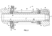
- the bicycle 10 includes a force sensor assembly 12 that is configured to sense the force applied by a cyclist (not shown) on a crank axle 14 (shown in Figure 2 ) as the cyclist applies force on a pair of bicycle pedals 16 (shown in Figure 1 ) that are coupled to the crank axle 14.
- the bicycle pedals 16 include conventional binding devices configured to releasably retain cleats on cycling shoes (not shown) in a conventional manner. Specifically, when mating cycling shoes are retained by the bicycle pedals 16, rotary power produced by the cyclist (not shown) is transmitted from the cycling shoes to the bicycle pedals 16 during both downward cycling motion and upward cycling motion.
- the bicycle 10 has a frame 18 and bicycle control devices 20.
- the frame 18 includes a down tube 22 ( Figures 1 and 3 only), a seat tube 24 ( Figures 1 and 3 only), a pair of chain stays 26 ( Figures 1 and 3 only) and a bottom bracket tube 28 ( Figures 2 and 3 only).
- the down tube 22, the seat tube 24 and the pair of chain stays 26 are all fixed to the bottom bracket tube 28 in a conventional manner.
- the frame 10 can be made of metallic tube sections welded together, or alternatively, can be made of composite materials such that the tubes of the frame 10 are fixed to one another by resin and/or carbon fiber materials. Since the frame 10 is a conventional feature of the bicycle 10, further description of the frame 10 is omitted for the sake of brevity.
- the bottom bracket tube 28 is a hollow element with open ends.
- the bottom bracket tube 28 is sometimes referred to simply as a bottom bracket or as a hanger.
- the bottom bracket tube 28 is configured to support the crank axle 14 and elements associated with the crank axle 14, as described in greater detail below.
- Each of the open ends of the bottom bracket tube 28 preferably include internal machine threads that supports the force sensor assembly 12 in a manner described in greater detail below.
- each of the open ends of the bottom bracket tube 28 can be dimensioned without machine threads to receive crank axle supporting elements via a press-fit arrangement that 14.
- the bicycle control devices 20 include (among other things) a control unit 32, a front derailleur 34, a set of chain rings 35, a rear derailleur 36, a rear sprocket set 37, a chain 38 that extends between the chain rings 35, the rear sprocket set 37, a rear gear shifting device 39, a front gear shifting device (hidden behind the rear gear shifting device 39 in Figure 1 ) and the force sensor assembly 12 (shown in Figures 2 and 3 ).
- the control unit 32 is attached to a forward section of the frame 18, such as the handlebars. As described in greater detail below, the control unit 32 is configured to determine the torque being applied to the crank axle 14 using strain measurement signals provided by the force sensor assembly 12. A description of the control unit 32 is proved below after a description of the force sensor assembly 12.
- the front derailleur 34 is attached to the seat tube 24 just above the bottom bracket tube 28 and the rear derailleur 36 is attached to one of the chain stays 26.
- the front derailleur 34 and the rear derailleur 36 are operated by respective ones of the front gear shifting device and the rear gear shifting device 39 in a conventional manner.
- the front derailleur 34, the rear derailleur 36, rear gear shifting device 39 and the front gear shifting device are conventional bicycle components. Therefore description of these components is omitted for the sake of brevity.
- the bottom bracket tube 28 is configured to receive and support a front crank assembly 40.
- the front crank assembly 40 is configured and dimensioned to rotatably support the crank axle 14.
- the front crank assembly 40 includes the crank axle 14 ( Figures 1 and 2 ), a right crank 44 ( Figures 1 and 2 only) detachably fixed to the right end of the crank axle 14, a left crank 46 ( Figures 1 and 2 only) fixed to the left end of the crank axle 14, a adapter 48, bearing rings 50 and 52, bearings 54 and 56, seals 58 and 60, seal guards 62 and 64, O-ring seals 66 and 68, spacers 70 and 72 and a dust tube 74.
- the spacers 70 and 72 are optional elements of the front crank assembly 40 and are used to adjust the position of the crank axle 14 relative to the front crank assembly 40.
- a conventional front crank assembly similar to the front crank assembly 40, such as that disclosed in U.S. Patent Application Publication No. 2003/0097900, published May 29, 2003 , typically includes a pair of threaded adaptors, like the threaded adaptor 48. However, in the present invention, one of the threaded adaptors is removed and replaced with the force sensor assembly 12.
- the crank axle 14 is a hollow cylindrical member that is rotatably mounted to extend through the bottom bracket tube 28, as shown in Figure 2 .
- the crank axle 14 is configured to rotate about a rotation axis A that extends through the center of the crank axle 14, the bearings 54 and 56 and the force sensor assembly 12, with the force sensor assembly 12 installed to the bottom bracket tube 28 the bearing 54 installed to the adaptor 48 and the bearing 56 installed to the force sensor assembly 12.
- the right crank 44 is fixed to the right side end of the crank axle 14 in a conventional manner.
- the left crank 46 is removably fixed to the left side end of the crank axle 14 in a conventional manner.
- the pedals 16 are attached to distal ends of respective ones of the right crank 44 and the left crank 46 in a conventional manner.
- the adapter 48 is dimensioned to threadedly attach to the left side of the bottom bracket tube 28 in a conventional manner.
- the adapter 48 is configured to receive and support the bearing ring 50, the bearing 54, the seal 58, the seal guard 62 and the O-ring seal 66.
- the threaded adaptor 48 also includes an internal surface 48a that is dimensioned to form a seal with and support one end of the dust tube 74, as indicated in Figure 2 .
- the machine threads on the threaded adaptor 48 can be eliminated and the threaded adaptor 48 can be press-fitted to the bottom bracket tube 28.
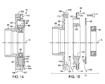
- the force sensor assembly 12 basically includes an adaptor member 80, a main body 82, a first side strain gauge 84, a second side strain gauge 86 and a cover 88.
- the first side strain gauge 84 is an outer side strain gauge because with the adaptor 48 of the force sensor assembly 12 mounted to the bottom bracket tube 28, the first side strain gauge 84 is disposed on an outboard side of the main body 82 facing away from the bicycle 10.
- the second side strain gauge 86 is an inner side strain gauge because with the adaptor 48 of the force sensor assembly 12 mounted to the bottom bracket tube 28, the second side strain gauge 86 is disposed on an inboard side of the main body 82 facing the bottom bracket tube 28 of the bicycle 10.
- the adaptor member 80 supports the main body 82 in a radial direction relative to the rotation axis A and in directions parallel to the rotational axis A. As indicated in Figure 3 , the adaptor member 80 is installed to the bottom bracket tube 28 such that the force sensor assembly 12 is disposed between the bottom bracket tube 28 and the chain rings 35. However, the adaptor member 80 of the present invention differs from the conventional adaptor 48, as described below.
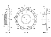
- the adaptor member 80 basically includes an attachment portion 90, an annular shaped flange 92 and a sensor mounting portion 94.
- the adaptor member 80 is preferably made of a metallic material, such as steel, aluminum, titanium or a suitable alloy with appropriate rigidity and strength.
- the attachment portion 90 has a tubular shape that includes machine threads 98 on an outer surface thereof and a seal lip 100 at a distal end.
- the machine threads 98 provide the attachment portion 90 with the means for removable attachment to the outboard side of the bottom bracket tube 28.
- the machine threads 98 can be omitted and the attachment portion 90 can be press-fitted to the outboard side of the bottom bracket tube 28.
- the seal lip 100 is configured to receive one end of the dust tube 74 and mate therewith thus creating a water tight seal between the dust tube 74 and the adaptor member 80, as indicated in Figures 2 and 3 .
- the tubular portion 98 is hollow such that the crank axle 14 extends therethrough, as indicated in Figure 2 .
- the annular shaped flange 92 extends radially outward from the tubular portion 98 of the attachment portion 90 joining the attachment portion 90 to the sensor mounting portion 94.
- the sensor mounting portion 94 is an annular shaped section of the adaptor member 80 that has a circumferentially extending outer surface 102, a circumferentially extending inner surface 104 and an axial end face 106.
- the sensor mounting portion 94 extends outward away from the attachment portion 90 of the adaptor member 80 and outward from the bottom bracket tube 28 with the adaptor member 80 installed to the bottom bracket tube 28. Further, the sensor mounting portion 94 is dimensioned to removably receive and retain the main body 82, as described in greater detail below.
- the outer surface 102 of the sensor mounting portion 94 includes a plurality of recesses 108 that are configured to assist in the installation and removal of the adaptor member 80 to and from the bottom bracket tube 28.
- the circumferentially extending inner surface 104 is dimensioned to receive the main body 82 such that the main body 82 is partially covered by the annular shaped flange 92 and the sensor mounting portion 94 within the interior space of the adaptor member 80 defined by the annular shaped flange 92 and the inner surface 104.
- the axial end face 106 includes a plurality of threaded apertures 110 that are circumferentially spaced apart from one another. The threaded apertures 110 are dimensioned to receive fasteners F that releasably fix the main body 82 to the adaptor member 80.
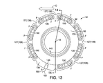
- the main body 82 includes an outer ring 120 (an outer portion), an inner ring 122 that is concentrically arranged within the outer ring 120, a first joining portion 124 and a second joining portion 126.
- the main body 82 is preferably made of a metallic material, such as steel, aluminum, titanium or a suitable alloy with appropriate rigidity and strength. The thickness and overall dimensions of the main body 82 are determined by the anticipated forces that will act on the crank axle 14, the materials used and the size and type of bicycle to be equipped with the force sensor assembly 12.
- the outer ring 120 is an annular shaped portion of the main body 82 that is removably attachable to the adaptor member 80 in a manner described below. Since the adaptor member 80 is removably attachable to an outboard side of the bottom bracket tube 28, the outer ring 120 is removably couple-able to the outboard side of the bottom bracket tube 28.
- the outer ring 120 includes a plurality of recesses 127, a first axial end face 128 and a second axial end face 129.
- the plurality of recesses 127 are dimensioned to correspond to the dimensions of the plurality of recesses 108 of the adaptor member 80.
- a plurality of arcuate elongated openings 130 are formed in the outer ring 120 that extend between the first and second axial end faces 128 and 129. The openings 130 are located at a diameter that coincides with the plurality of apertures 110 in the sensor mounting portion 94 of the adaptor member 80.
- the fasteners F extend through corresponding ones of the arcuate elongated openings 130 and into the apertures 110 in order to releasably secure the main body 82 to the adaptor member 80.
- the arcuate elongated openings 130 have an arcuate length that is dimensioned to provide angular adjustment of the position of the outer ring 120 relative to the adaptor member 80. Specifically, the position of the outer ring 120 relative to the adaptor member 80 can be angularly adjusted with an overall range of approximately 35 degrees about the rotation axis A.
- Each of the arcuate elongated openings 130 is chamfered such that a recess 132 surrounds each of the arcuate elongated openings 130.
- a section 134 of the outer ring 120 is solid having no opening formed therein.
- the section 134 is instead provided with a recess 136 that extends radially outward along the surface of the outer ring 120.
- the inner ring 122 is a crank axle bearing mounting portion that is concentrically arranged within the outer ring 120.
- the inner ring 122 is dimensioned to receive and support the bearing 56 (one of the crank axle bearings) that rotatably supports the crank axle 14. More specifically, the inner ring 122 has an inner surface 140 that extends circumferentially.
- the inner ring 122 is dimensioned to receive and retain the bearing 56 in a conventional manner, for example, in a press-fit engagement.
- inner ring 122 is radially spaced apart from the outer ring 120 (the outer portion) with a crank axle bearing mounting portion defined on an inner radial surface of the inner ring 122.
- the outer ring 120 encircles the inner ring 122, thus circumferentially surrounding the inner ring 122.
- the inner ring 122 is concentrically arranged within the outer ring 120.
- the outer ring 120 and the inner ring 122 of the main body 82 are spaced apart from one another in the radial direction and fixed to one another by the first joining portion 124 and the second joining portion 126.
- the first joining portion 124 extends in a radial direction between the inner ring 122 and the outer ring 120.
- the second joining portion 126 extends between the inner ring 122 and the outer ring 120 in a direction that is angularly offset from a plane P (see Figures 9 and 12 ) that coincides with and extends along the rotation axis A of the crank axle 14 with the adaptor member 80 installed to the bottom bracket tube 28.
- the plane P is also preferably a vertical plane (perpendicular to horizontal).
- the adaptor member 80 installed to the bottom bracket tube 28 such that the orientation of the first and second strain gauges 84 and 86 are oriented with respect to the plane P, as indicated in Figures 9 , 16 and 17 .
- first joining portion 124 and the second joining portion 126 are circumferentially spaced apart from one another by approximately 180 degrees. As indicated in Figure 9 , the first joining portion 124 is located at a top section of the inner ring 122 (relative to the depiction in Figure 9 ) and the second joining portion 126 is located at a bottom section of the inner ring 122 (relative to the depiction in Figure 9 ). Elongated arcuate openings 142 and 144 are defined between the inner ring 122, the outer ring 120, the first joining portion 124 and the second joining portion 126, as best shown in Figures 7 and 9 . The recess 136 in the section 134 of the outer ring 120 extends between the elongated arcuate opening 144 and a radial outer edge of the outer ring 120.
- the first joining portion 124 has a first circumferential side 146 and a second circumferential side 148.
- the first circumferential side 146 and the second circumferential side 148 are asymmetric relative to one another and to the plane P ( Figures 9 and 12 ) that extends through the rotation axis A ( Figure 9 ).
- the second circumferential side 148 is larger than the first circumferential side 146.
- An arrow representing a chain tension direction C is shown in Figures 12 and 15 .
- the chain tension direction C represents the tension on the chain 38 during cycling.
- the arrow representing the chain tension direction C points from an upper region of the front crank assembly 40 toward the rear derailleur 36.
- the orientation and overall shape of the first joining portion 124 shown in Figure 12 is important for optimizing the forces detected by the first and second strain gauges 84 and 86 on the second joining portion 126 (described in greater detail below). More specifically, the overall shape of the first joining portion 124 is provided to counter the tension on the chain 38 acting the chain tension direction C.
- the second joining portion 126 has first and second circumferential sides that are symmetrical to one another about the plane P, as indicated in Figure 11 .
- the second joining portion 126 includes a first axial end side shown in Figures 9 and 16 , and a second axial end side shown in Figure 7 .
- the first axial end side of the second joining portion 126 includes a first sensor mounting surface 150 and the second axial end side of the second joining portion 126 includes a second sensor mounting surface 152.
- the first sensor mounting surface 150 and the second sensor mounting surface 152 extend between the outer ring 120 and the inner ring 122.
- the force sensor assembly 12 is dimensioned to threadedly attach to the right side of the bottom bracket tube 28 and is configured to receive and support the bearing ring 52, the bearing 56, the seal 60, the seal guard 64 and the O-ring seal 68.
- the force sensor assembly 12 also includes the seal lip 100 that is dimensioned to form a seal with and support one end of the dust tube 74.
- first sensor mounting surface 150 and the second sensor mounting surface 152 are oriented such that they are substantially perpendicular to the plane P and the rotation axis A.
- the first sensor mounting surface 150 and the second sensor mounting surface 152 are also oriented such that they are parallel to the first axial end face 128 and the second axial end face 129 of the outer ring 120.
- the first sensor mounting surface 150 and the second sensor mounting surface 152 are substantially parallel to one another.
- the first sensor mounting surface 150 and the second sensor mounting surface 152 can be angularly offset from the first axial end face 128 and the second axial end face 129 of the outer ring 120 by up to 15 degrees.
- first and second sensor mounting surfaces 150 and 152 extend in a direction perpendicular to a rotation axis A of the crank axle 14 with the force sensor assembly 12 coupled to the bottom bracket tube 28.
- the first side strain gauge 84 includes a first gauge 84a and a second gauge 84b.
- the second side strain gauge 86 includes a third gauge 86a and a fourth gauge 86b.
- the first side strain gauge 84 and the second side strain gauge 86 are preferably identical to one another, except that they are mounted to opposite sides of the second joining portion 126. More specifically, the first side strain gauge 84 is fixed to the first sensor mounting surface 150 and the second side strain gauge 86 is fixed to the second sensor mounting surface 152, as shown in Figures 2 , 11 , 14 and 15 .
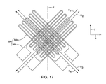
- first side strain gauge 84 and the second side strain gauge 86 are identical, description of one applies to both. Therefore, in the following description, only the first gauge 84a and the second gauge 84b of the first side strain gauge 84 are described in detail with respect to Figures 16 and 17 . However, the description applies equally to the third gauge 86a and the fourth gauge 86b of the second side strain gauge 86.
- the first gauge 84a and the second gauge 84b of the first side strain gauge 84 are fixed to the first sensor mounting surface 150. However, both the first gauge 84a and the second gauge 84b are angularly offset from the plane P that coincides with the rotation axis A. Since the plane P also extends along the rotational axis A of the crank axle 14 with the adaptor member installed to the bottom bracket tube 28, the first gauge 84a and the second gauge 84b are also angularly offset from the rotational axis A. Similarly, the second side strain gauge 86 is fixed to the second sensor mounting surface 152 and the third gauge 86a and the fourth gauge 86b are angularly offset from the plane P that coincides with the rotation axis A.
- first gauge 84a and the second gauge 84b both extend in directions that are angularly offset from the radial direction of the inner ring 122 and the outer ring 120.
- the radial direction coincides with the plane P, as indicated in Figures 7 and 9 .
- the first gauge 84a has first strain measurement directions D 1 and D 2 .
- the first strain measurement directions D 1 and D 2 are substantially parallel to one another because conventional strain gauges typically only respond to strain in one direction.
- the first strain measurement direction D 1 represents a slight elongation of the first gauge 84a in response to forces applied to the main body 82.
- the first strain measurement direction D 2 represents a slight compression of the first strain gauge 84 in response to forces applied to the main body 82.
- the second gauge 84b has second strain measurement directions D 3 and D 4 .
- the second measurement directions D 3 and D 4 are substantially parallel to one another because conventional strain gauges typically only respond to strain in one direction.
- the second strain measurement direction D 3 represents a slight elongation of the second gauge 84b in response to forces applied to the main body 82.
- the second strain measurement direction D 4 represents a slight compression of the second gauge 84b in response to forces applied to the main body 82.
- the first gauge 84a and the second gauge 84b and their respective first and second strain measurement directions D 1 , D 2 , D 3 and D 4 extend in directions that are angularly offset from the radial direction of the inner ring 122 and the outer ring 120 (and the plane P) by an angle of substantially 45 degrees. Further, the second gauge 84b is angularly offset from the first gauge 84a by an angle of substantially 90 degrees. Further, the first strain measurement directions D 1 and D 2 and the second strain measurement directions D 3 and D 4 are symmetrical with respect to the plane P.
- first strain measurement directions D 1 and D 2 are angularly offset from the plane P by 45 degrees in a clockwise direction as viewed in Figure 17 and the second strain measurement directions D 3 and D 4 are angularly offset from the plane P by 45 degrees in a counterclockwise direction as viewed in Figure 17 .
- the first side strain gauge 84 includes a cable 160 extending therefrom configured to carry electric signals to and from the first side strain gauge 84.
- the second side strain gauge 86 includes a cable 162 extending therefrom to carry electric signals to and from the second side strain gauge 86.
- the cables 160 and 162 each include four conductive lines or wires. Specifically as shown in Figure 16 , the cable 160 includes four wires, two of the wires being electrically connected to opposite sides of the first gauge 84a and two wires being connected to opposite sides of the second gauge 84b in a conventional manner. Similarly, the cable 162 has four wires connected in a conventional manner to the third and fourth gauges 86a and 86b.
- the cables 160 and 162 are laid within the recess 132 on the outer ring 120.
- the cables 160 and 162 extend from the first and second side strain gauges 84 and 86, through the recess 132 and outside the force sensor assembly 12. Once the first and second side strain gauges 84 and 86 have been installed and the cables 150 and 152 are in position within the recess 136, the recess is filled in with a resin material or other similar adhesive material that retains the cables 160 and 162 in position within the recess 136.
- the cover 88 is an annular member that is preferably made of an electrically insulating material that is also water resistant.
- the cover 88 is fixed to the main body 82 such that the cover 88 covers the first strain gauge 84, the elongated arcuate openings 142 and 144. Consequently, the cover 88 encloses and seals the force sensor assembly 12 against water and debris, thus protecting the first and second strain gauges 84 and 86 against the elements (dust, water, debris, etc).
- the inner ring 122 is an annular member of the main body 82 that is positioned concentrically within the outer ring 120.
- the inner ring 122 is rigid relative to the designed intended usage.
- the first and second joining portions 124 and 126 are dimensioned and shaped to undergo limited elastic deformation that is measurable by the first and second side strain gauges 84 and 86.
- the first and second side strain gauges 84 and 86 are fixed to the second joining portion 126 of the main body 82 of the force sensor assembly 12.
- the inner ring 122 of the main body 82 supports the bearing 56 and the crank axle 14 is supported by the bearing 56.
- the first and second joining portions 124 and 126 are dimensioned to flex slightly, thereby elastically deforming.
- the elastic deformation of the second joining portion 126 is measured by the first and second side strain gauges 84 and 86.
- the first and second side strain gauges 84 and 86 are conventional strain gauges sometimes referred to foil strain gauges that are fixed to the desired surface using a conventional adhesive appropriate for strain gauges. However, it should be understood from the drawings and the description herein that any of a variety of strain measuring devices can be used with the present invention. Specifically, the first and second side strain gauges 84 and 86 can be replaced with other types of strain measuring devices.
- the strain data measured by the first and second side strain gauges 84 and 86 is used by the control unit 32 to calculate and display torque information. Specifically, the control unit 32 calculates at least one of: the tension on the chain 38; the torque on the crank axle 14; and the power on the bicycle pedals 16.
- the control unit 32 calculates at least one of: the tension on the chain 38; the torque on the crank axle 14; and the power on the bicycle pedals 16.
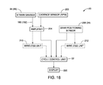
- a description of those elements of the bicycle 10 that are in electrical communication with the control unit 32 and used to calculate the tension on the chain 38, torque on the crank axle 14 and/or the power on the bicycle pedals 16 is now provided with specific reference to Figure 18 .
- the following elements are in electronic communication with the control unit 32: the first and second side strain gauges 84 and 86, a cadence sensor 200, an amplifier 204 and a gear positioning sensor 206.
- the cadence sensor 200 is a conventional device that is typically mounted to the down tube 22, the seat tube 24 or one of the chain stays 26.
- the cadence sensor 200 is a device that detects the angular position of one of the right crank 44 and/or the left crank 46 and the revolutions per minute (RPM) of the crank axle 14.
- the cadence sensor 200 can, for example, include a magnetic field detecting device that detects magnetic fields of an adjacent one of the right crank 44 and the left crank 46 as the crank passes by the cadence sensor 200 during cycling. Further, one of the right crank 44 and the left crank 46 is provided with a magnet (not shown) that is detected by the cadence sensor 200 as the crank axle 14 rotates.
- the cadence sensor 200 can alternatively be any of a variety of RPM measuring devices.
- the cadence sensor 200 is electrically connected to the amplifier 204.
- the amplifier 204 is in electrical communication with the first and second side strain gauges 84 and 86 and the cadence sensor 200. Specifically, the cables 160 and 162 of the first and second side strain gauges 84 and 86 are electrically connected to amplifier 204.
- the amplifier 204 is a conventional electrical component that detects changes in electrical properties of the first and second side strain gauges 84 and 86 and detects the RPM of the crank axle 14 measured by the cadence sensor 200.
- the amplifier 204 can be installed within the control unit 32 or can be a separate modular unit positioned adjacent to or within the force sensor assembly 12.
- the amplifier 204 is preferably mounted to the frame 18 adjacent to the bottom bracket tube 28. Alternatively, the amplifier 204 can be mounted within the main body 82 within one of the elongated arcuate openings 142 and 144.
- the gear positioning sensor 206 is a conventional device that is installed in the front derailleur 34 and provides signals to the control unit 32 indicating the position of the bicycle chain 38 relative to plurality of chain rings of the set of chain ring 35 ( Figure 1 ). Each chain ring of the set of chain rings 35 has its own unique diameter. Since the gear positioning sensor 206 is a conventional device, further description is omitted for the sake of brevity.
- the cables 160 and 162 of the first and second side strain gauges 84 and 86 and the cadence sensor 200 are electrically connected to, or are in electrical communication with the control unit 32 via the amplifier 204.
- the gear positioning sensor 206 is also electrically connected to the control unit 32.
- the bicycle 10 can alternatively be provided with wireless communication devices 210 and 212.
- the wireless communication device 210 can provide a wireless communication link between the amplifier 204 and the control unit 32.
- the wireless communication device 212 can provide a wireless communication link between the gear position sensor 206 and the control unit 32.
- the wireless communication device 212 can be disposed within the main body 82 within one of the elongated arcuate openings 142 and 144.
- the control unit 32 is preferably a processing unit that includes a display 220 that is configured to display power data to the cyclist riding the bicycle 10.
- the control unit 32 is configured and arranged to receive the RPM data from the cadence sensor 200, gear position data from the gear positioning sensor 206 and force data from the first and second side strain gauges 84 and 86.
- the control unit 32 calculates at least one of tension on the chain 38, torque on the crank axle 14 and power per rotation on the pedals 16 produced by the cyclist in response to receiving the RPM data from the cadence sensor 200, the gear position data from the gear positioning sensor 206 and the strain data from the first and second side strain gauges 84 and 86.
- the control unit 32 then displays the calculated power and RPM on the display 220.
- the display 220 can be part of the control unit 32 or can be a separate component electronically connected to the control unit 32.
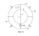
- the information depicted in Figures 19-22 demonstrates the logic used to determine the operations of the control unit 32.
- the control unit 32 subtracts the value of one of the first gauge 84a and the second gauge 84b from the other one of the first gauge 84a and the second gauge 84b and further subtracts the value of one of the third gauge 86a and the fourth gauge 86b from the other one of the third gauge 86a and the fourth gauge 86b.
- This set of calculations eliminated forces acting in a vertical direction from the overall data and provides the value of strain in the chain tension direction C.
- the first and second gauges 84a and 84b are connected to a conventional Wheatstone bridge circuit (not shown).
- the third and fourth gauges 86a and 86b are connected to another conventional Wheatstone bridge circuit (not shown).
- the resulting voltage output is provided to the control unit 32 and provides the basis for the value of strain and the level of chain tension in the chain tension direction C.
- Figure 19 depicts four crank position regions and calculated crank positions corresponding to calculated positions of the right crank 44.
- the number one (1) represents a 90 degrees angular region of a rotation of the crank axle 14.
- the number one (1) represents the position of the right crank 44 in a corresponding angular position relative to the rotation axis A.
- the number two (2) represents a second 90 degree angular region of one rotation of the crank axle 14.
- the number two (2) represents the position of the right crank 44 in a corresponding angular position relative to the rotation axis A.
- the number three (3) represents a third 90 degree angular region of one rotation of the crank axle 14.
- the number two (2) represents the position of the right crank 44 in a corresponding angular position relative to the rotation axis A.
- the number four (4) represents a fourth 90 degree angular region of one rotation of the crank axle 14.
- the number two (2) represents the position of the right crank 44 in a corresponding angular position relative to the rotation axis A.
- the strain at each of the four crank position regions is measured by the first and second side strain gauges 84 and 86.
- the actual position of the crank axle 14 relative to the rotation axis A is determined by signals from the cadence sensor 200. Since the cadence sensor 200 also provides predetermined crank position data and RPM data, some crank positions are easily determined. For example, with a sampling frequency F 1 measured in Hz (hertz) and a time T 1 seconds per rotation of the crank axle 14, then by dividing F 1 by T1 (F 1 /T 1 ) the crank positions are obtained.
- Figure 20 represents strain measured by the first and second side strain gauges 84 and 86 (outboard and inboard side strain gauges) in a single rotation of the crank axle 14, with the four crank position regions one (1), two (2), three (3) and four (4).
- the strain measured changes depending upon the position of the crank.
- the first and second side strain gauges 84 and 86 have differing responses depending upon the chain tension.
- the control unit 32 utilizes signals from the cadence sensor 200 to determine the actual rotational location of the crank axle 14 and crank 44 (46) and can therefore correlate detected average strain to each of the four crank position regions.
- the control unit 32 is programmed and/or configured to take the strain variations in all crank position regions into account using compensating constants that are discussed further below.
- chain tension (N) was measured independently and separately from the strain detected by the first and second side strain gauges 84 and 86. Specifically, known amounts of chain tension (N) were applied to the crank axle 14 and strain was measured using the first and second side strain gauges 84 and 86.
- the outboard strain readings from the first side strain gauge 84 (the first gauge 84a and the second gauge 84b) was greater at larger chain tension amounts that inboard strain readings from the second side strain gauge 86 (the third gauge 86a and the fourth gauge 86b). These measurements are represented in Figure 21 .
- a hysteresis effect is noticeable at differing levels of chain tension (N) and the detected strain due in part because of the effects of strain measured at all crank positions represented in Figure 20 .
- the control unit 32 can compensate for this hysteresis effect.
- Figure 22 shows measured chain tension (N) and calculated chain tension calculated using the signals from the first and second side strain gauges 84 and 86, the gear positioning sensor 206 and the compensating constants.
- the calculated chain tension is linear with the real or separately measured chain tension (N).
- the control unit 32 can use the signals from the first and second side strain gauges 84 and 86 and the gear positioning sensor 206 (34) accurately calculate and display the torque being applied to the chain by a cyclist pedaling on the bicycle 10.
- the gear positioning sensor 206 provides information on the chain location relative to the front sprockets.
- the relative diameter of each chain ring of the set of chain rings 35 is stored in memory within the control unit 32. Hence, the distance between the rotation axis A and teeth of each chain ring of the set of chain rings 35 is easily determined by the control unit 32.
- the sensitivity of the first and second side strain gauges 84 and 86 differs at the four crank position regions one (1), two (2), three (3) and four (4).
- a more consistent and reliable calculated chain tension is provided by the control unit 32.
- using the compensation constants a 1 through a 8 eliminates the different levels of sensitivity between the first and second side strain gauges 84 and 86 at differing crank angles.
- the constants a 9 and 1 in the above equation compensate for rotation when there is no tension on the chain (no torque) even though under such circumstances strain is measured.
- the configuration of the force sensor assembly 12 allows for easy installation to both new and previously used bicycles.
- the configuration of the force sensor assembly 12 allows for an increase in strain measurement sensitivity and allows for an accurate calculation of chain tension, pedaling power and crank axle torque.
- the configuration of the force sensor assembly 12 allows for the adjustment of the vertical positioning of the main body 82.
- the first and second joining portions 124 and 126 can be oriented vertically one above the other.
- first and second joining portions 124 and 126 oriented vertically one above the other.
- the vertical alignment of the first and second joining portions 124 and 126 is possible with the force sensor assembly 12 by the inclusion of the arcuate elongated openings 130 in the outer ring 120 of the main body 82. Loosening the fasteners F allows for angular positioning of the main body 82 relative to the adaptor member 80 and the frame 18 of the bicycle 10.
- the plurality of recesses 127 can be aligned to correspond to the location of the plurality of recesses 108 of the adaptor member 80.
- the front derailleur 34 and the rear derailleur 36 are manually shifted between chain rings by the cyclist in a conventional manner.
- the force sensor assembly 12 can also be employed on a bicycle with an automatic gear shifting system.
- the calculated chain tension (crank axle torque) and power can be used by a modified control unit to determine optimal shifting speeds based upon the chain tension and current gear speed.
- the control unit 32 preferably includes a microcomputer with a bicycle control program that controls the display 220 and performs calculations based upon data input.
- the control unit 32 can also include other conventional components such as an input interface circuit, an output interface circuit, and storage devices such as a ROM (Read Only Memory) device and a RAM (Random Access Memory) device.
- the microcomputer of the control unit 32 is programmed to control the display 220 but can alternatively also be programmed to control automated shifting of the chain position.
- the memory circuit stores processing results and control programs such as ones for derailleur positioning operations that are run by the processor circuit.
- the internal RAM of the control unit 32 stores statuses of operational flags and various control data.
- control unit 32 can be any combination of hardware and software that will carry out the functions of the present invention. While only selected embodiments have been chosen to illustrate the present invention, it will be apparent to those skilled in the art from this disclosure that various changes and modifications can be made herein without departing from the scope of the invention as defined in the appended claims. Furthermore, the foregoing descriptions of the embodiments according to the present invention are provided for illustration only, and not for the purpose of limiting the invention as defined by the appended claims and their equivalents.
Landscapes
- Engineering & Computer Science (AREA)
- Mechanical Engineering (AREA)
- Physics & Mathematics (AREA)
- General Physics & Mathematics (AREA)
- Chemical & Material Sciences (AREA)
- Combustion & Propulsion (AREA)
- Transportation (AREA)
- Force Measurement Appropriate To Specific Purposes (AREA)
Applications Claiming Priority (1)
| Application Number | Priority Date | Filing Date | Title |
|---|---|---|---|
| US12/463,154 US8117923B2 (en) | 2009-05-08 | 2009-05-08 | Bicycle bottom bracket force sensor |
Publications (3)
| Publication Number | Publication Date |
|---|---|
| EP2248715A2 true EP2248715A2 (de) | 2010-11-10 |
| EP2248715A3 EP2248715A3 (de) | 2011-10-19 |
| EP2248715B1 EP2248715B1 (de) | 2015-07-08 |
Family
ID=42556443
Family Applications (1)
| Application Number | Title | Priority Date | Filing Date |
|---|---|---|---|
| EP09171257.0A Active EP2248715B1 (de) | 2009-05-08 | 2009-09-24 | Kraftsensor für Fahrradtretlager |
Country Status (4)
| Country | Link |
|---|---|
| US (1) | US8117923B2 (de) |
| EP (1) | EP2248715B1 (de) |
| CN (1) | CN101881674B (de) |
| TW (1) | TWI482721B (de) |
Cited By (9)
| Publication number | Priority date | Publication date | Assignee | Title |
|---|---|---|---|---|
| NL2009882A (en) * | 2012-04-23 | 2013-10-28 | Ebm Solutions Pty Ltd | Bottom bracket adaptor for bicycle transmission. |
| CN103373431A (zh) * | 2012-04-25 | 2013-10-30 | 株式会社岛野 | 自行车曲柄臂 |
| WO2014036011A1 (en) * | 2012-08-28 | 2014-03-06 | Foundation Fitness, LLC | Apparatus, system and method for power measurement at a crank axle and crank arm |
| US9315071B2 (en) | 2013-07-12 | 2016-04-19 | Slipstream Bicycles, Llc | Bicycle wheel system |
| NL2016177B1 (en) * | 2016-01-28 | 2017-08-01 | Tacx Roerend En Onroerend Goed B V | Bicycle, comprising a frame provided with a cadence sensor. |
| WO2018041948A1 (de) * | 2016-08-31 | 2018-03-08 | Sensodrive Gmbh | Drehmomentsensor mit radialelastischer momentübertragung |
| US9921118B2 (en) | 2012-01-23 | 2018-03-20 | Foundation Fitness, LLC | Apparatus, system and method for power measurement at a crank axle and crank arm |
| US10989614B2 (en) | 2017-04-10 | 2021-04-27 | Fanuc Corporation | Torque sensor and robot |
| EP3933221A4 (de) * | 2020-04-27 | 2022-06-15 | Harmonic Drive Systems Inc. | Lagervorrichtung und wellenbewegungsgetriebe |
Families Citing this family (43)
| Publication number | Priority date | Publication date | Assignee | Title |
|---|---|---|---|---|
| EP1914577A1 (de) * | 2006-10-17 | 2008-04-23 | British Telecommunications Public Limited Company | Faseroptisches Installationsgerät |
| EP2075606A1 (de) * | 2007-12-28 | 2009-07-01 | British Telecmmunications public limited campany | Kabelinstallation mithilfe von Induktion |
| EP2075608A1 (de) * | 2007-12-28 | 2009-07-01 | British Telecmmunications public limited campany | Kabelinstallation mithilfe optischer Erkennung |
| GB0817639D0 (en) * | 2008-09-26 | 2008-11-05 | British Telecomm | Cable installation apparatus |
| EP2230545A1 (de) | 2009-03-19 | 2010-09-22 | BRITISH TELECOMMUNICATIONS public limited company | Passive entfernte Luftstrom- und Kabeldetektion |
| GB0905590D0 (en) | 2009-03-31 | 2009-05-13 | British Telecomm | Blown cable apparatus |
| WO2010139350A1 (en) * | 2009-06-05 | 2010-12-09 | Skf Bv | Load-measuring bearing unit |
| US20120330572A1 (en) * | 2009-11-28 | 2012-12-27 | David John Longman | Cyclic Cranked System Method and Related Devices |
| EP2369388A1 (de) | 2010-03-26 | 2011-09-28 | British Telecommunications public limited company | Spleisskassettenmodul für optische Faser |
| US9010201B2 (en) * | 2010-10-22 | 2015-04-21 | Pioneer Corporation | Measurement apparatus and method |
| US11280689B2 (en) * | 2011-01-21 | 2022-03-22 | Foundation Fitness Llc | Apparatus, system and method for power measurement at a crank axle and crank arm |
| US8746081B2 (en) * | 2011-05-10 | 2014-06-10 | Shimano Inc. | Bicycle force sensing assembly |
| US8453521B2 (en) * | 2011-05-10 | 2013-06-04 | Shimano Inc. | Bicycle force sensing device |
| DE102011077181A1 (de) * | 2011-06-08 | 2012-12-13 | Robert Bosch Gmbh | Verfahren und Vorrichtung zur Verschleißerkennung an einem Elektrofahrrad |
| EP2734822A1 (de) * | 2011-07-18 | 2014-05-28 | Michael J. Grassi | Drehmomentsensor |
| JP5607003B2 (ja) | 2011-08-29 | 2014-10-15 | 株式会社シマノ | 自転車用センサの制御装置、自転車用センサの制御方法 |
| JP2013047657A (ja) | 2011-08-29 | 2013-03-07 | Shimano Inc | 自転車用センサの制御装置、自転車用センサの制御方法 |
| US8800389B2 (en) * | 2012-03-07 | 2014-08-12 | Shimano, Inc. | Bicycle crank arm with an input force processing apparatus |
| TWI540077B (zh) * | 2012-03-07 | 2016-07-01 | 島野股份有限公司 | 自行車曲柄臂 |
| US8833182B2 (en) | 2012-03-07 | 2014-09-16 | Toshio Tetsuka | Bicycle input force processing apparatus |
| CN103454022A (zh) * | 2012-05-31 | 2013-12-18 | 童国林 | 一种骑行自行车做功测量系统及方法 |
| US8825279B2 (en) | 2012-09-11 | 2014-09-02 | Shimano Inc. | Bicycle power sensing apparatus |
| CN103257011B (zh) * | 2013-05-03 | 2014-12-31 | 尚林山 | 一种曲柄扭矩测量装置及电动自行车和智能自行车 |
| US9607596B2 (en) | 2013-05-06 | 2017-03-28 | Viatran Corporation | Pressure transducer |
| US10000249B2 (en) * | 2014-08-22 | 2018-06-19 | Shimano Inc. | Bicycle pedal |
| ES2535582B1 (es) * | 2015-01-19 | 2016-01-25 | Rotor Componentes Tecnológicos S.L. | Dispositivo de medición del par y la potencia de pedaleo en una bicicleta |
| US9581508B2 (en) | 2015-01-23 | 2017-02-28 | Shimano Inc. | Bicycle pedaling force detector |
| JP6427034B2 (ja) * | 2015-02-27 | 2018-11-21 | 日立金属株式会社 | トルク検出装置、及びトルク検出方法 |
| US10591371B2 (en) | 2016-06-10 | 2020-03-17 | Level Engineering, Inc. | Systems and methods for measuring drivetrain power transmission |
| CN109415100A (zh) * | 2016-06-30 | 2019-03-01 | 福特全球技术公司 | 带有可拆卸电池组的数据采集装置 |
| DE112016006945T5 (de) * | 2016-06-30 | 2019-03-28 | Ford Global Technologies, Llc | Systeme, verfahren und vorrichtungen für einen rahmenfesten pedaltrittfrequenzsensor |
| TWI606958B (zh) | 2016-09-14 | 2017-12-01 | 達方電子股份有限公司 | 使用於助力腳踏車的曲柄傳動機構 |
| EP3501961A1 (de) * | 2017-12-20 | 2019-06-26 | Specialized Bicycle Components, Inc. | Fahrradpedaldrehmomenterfassungssysteme, verfahren und vorrichtungen |
| US20190300105A1 (en) * | 2018-03-28 | 2019-10-03 | GM Global Technology Operations LLC | E-assist reservation and optimization for an e-bike |
| FR3095185B1 (fr) | 2019-04-17 | 2022-04-22 | Mavic Sas | Capteur de mesure d ’effort pour pédalier |
| FR3095269B1 (fr) | 2019-04-17 | 2021-11-26 | Mavic Sas | Capteur de mesure d ’effort |
| TWI685441B (zh) * | 2019-05-07 | 2020-02-21 | 銘穗精密工業有限公司 | 自行車五通碗組結構 |
| ES2792773A1 (es) * | 2019-05-10 | 2020-11-11 | Bikone Bearings S L | Dispositivo de medicion de la potencia de pedaleo |
| FR3099747B1 (fr) | 2019-08-07 | 2022-03-18 | Mavic Sas | Procédé automatique de commande en courant d’un moteur d’assistance au pédalage sur un vélo à assistance électrique et vélo à assistance électrique prévu pour la mise en œuvre d’un tel procédé |
| US11292544B2 (en) * | 2019-08-16 | 2022-04-05 | Giant Manufacturing Co., Ltd. | Bicycle and spider capable of measuring power |
| US11511826B2 (en) * | 2019-12-09 | 2022-11-29 | Sram, Llc | Bicycle axle assembly including a power meter |
| JP2022107207A (ja) * | 2021-01-08 | 2022-07-21 | 日本電産コパル電子株式会社 | トルクセンサ |
| JP2022146359A (ja) * | 2021-03-22 | 2022-10-05 | 日本電産コパル電子株式会社 | センサ |
Citations (8)
| Publication number | Priority date | Publication date | Assignee | Title |
|---|---|---|---|---|
| US4112751A (en) | 1976-06-28 | 1978-09-12 | Gruenbaum Heinrich | Arrangement for measuring a radial force applied to a bearing |
| DE19646979A1 (de) | 1996-11-06 | 1998-09-24 | Dietrich Gerhard Ellsaesser | Leistungssteuerung für Fahrradzusatzantriebe |
| WO2001030643A1 (en) | 1999-10-19 | 2001-05-03 | Idbike | Method and device for measuring the effort made by a cyclist |
| US6269702B1 (en) | 1998-10-30 | 2001-08-07 | Vernon A. Lambson | Method and apparatus for measuring torque |
| WO2002047551A2 (de) | 2000-12-12 | 2002-06-20 | Feo Elektronik Gmbh | Ergometer mit einer im bereich einer wellenlagerung angeordneter sensoreinheit |
| US20030097900A1 (en) | 2001-11-23 | 2003-05-29 | Shimano, Inc. | Seal assembly for a bicycle bottom bracket |
| US20080236293A1 (en) | 2007-04-02 | 2008-10-02 | Campagnolo S.R.L. | Instrument-equipped bicycle component and detection unit for equipping such a component |
| US7516677B2 (en) | 2007-04-03 | 2009-04-14 | Shimano Inc. | Torsion detecting sleeve member and torque-detecting device |
Family Cites Families (17)
| Publication number | Priority date | Publication date | Assignee | Title |
|---|---|---|---|---|
| DE1958645A1 (de) * | 1968-11-26 | 1970-07-30 | Matsushita Electric Ind Co Ltd | Tretkurbellager fuer Fahrraeder |
| DE2647440C3 (de) * | 1976-10-21 | 1982-02-11 | MTU Motoren- und Turbinen-Union München GmbH, 8000 München | Verfahren zur Bestimmung des statischen Achsschubes bei Lagern unter extremen Betriebsbedingungen |
| DE2911479C2 (de) * | 1979-03-22 | 1983-09-29 | Lechler, Gerhard, Dr.-Ing., 1000 Berlin | Kraftmeßeinrichtung |
| FR2631703B1 (fr) * | 1988-05-17 | 1990-08-10 | Look Sa | Roue motrice de cycle ou similaire, comportant un systeme de detection du couple transmis, et cycle equipe d'une telle roue |
| US5140849A (en) * | 1990-07-30 | 1992-08-25 | Agency Of Industrial Science And Technology | Rolling bearing with a sensor unit |
| US5758736A (en) * | 1995-03-29 | 1998-06-02 | Suzuki Kabushiki Kaisha | Power assist apparatus of power assisted bicycle |
| JP3373371B2 (ja) * | 1996-09-20 | 2003-02-04 | 株式会社シマノ | 自転車の変速制御装置 |
| JPH11258078A (ja) | 1998-03-09 | 1999-09-24 | Toyoda Mach Works Ltd | トルク検出装置 |
| US5952587A (en) * | 1998-08-06 | 1999-09-14 | The Torrington Company | Imbedded bearing life and load monitor |
| TW409104B (en) * | 1998-09-01 | 2000-10-21 | Shimano Kk | Torque sensor for bicycle and crankshaft assembly for bicycle |
| US6196347B1 (en) * | 1998-09-22 | 2001-03-06 | Industrial Technology Research Institute | Power transmission and pedal force sensing system for an electric bicycle |
| US6263992B1 (en) * | 1999-08-17 | 2001-07-24 | Shu-Shian Li | Torque detection device |
| US6490935B1 (en) * | 1999-09-28 | 2002-12-10 | The Timken Company | System for monitoring the operating conditions of a bearing |
| NL1016756C2 (nl) * | 2000-11-30 | 2002-05-31 | Skf Eng & Res Centre Bv | Meetelement voor het meten van radiale en/of axiale krachten op een lager. |
| ITTO20010730A1 (it) * | 2001-07-24 | 2003-01-24 | Campagnolo Srl | Trasduttore di grandezze angolari. |
| TWM265320U (en) * | 2004-09-08 | 2005-05-21 | Chuen-Lin Jang | Pressurization mechanism with force sensing device |
| US7806006B2 (en) * | 2007-11-08 | 2010-10-05 | Grand Valley State University | Bicycle torque measuring system |
-
2009
- 2009-05-08 US US12/463,154 patent/US8117923B2/en not_active Expired - Fee Related
- 2009-08-14 TW TW098127482A patent/TWI482721B/zh active
- 2009-09-07 CN CN2009101716874A patent/CN101881674B/zh active Active
- 2009-09-24 EP EP09171257.0A patent/EP2248715B1/de active Active
Patent Citations (9)
| Publication number | Priority date | Publication date | Assignee | Title |
|---|---|---|---|---|
| US4112751A (en) | 1976-06-28 | 1978-09-12 | Gruenbaum Heinrich | Arrangement for measuring a radial force applied to a bearing |
| DE19646979A1 (de) | 1996-11-06 | 1998-09-24 | Dietrich Gerhard Ellsaesser | Leistungssteuerung für Fahrradzusatzantriebe |
| US6269702B1 (en) | 1998-10-30 | 2001-08-07 | Vernon A. Lambson | Method and apparatus for measuring torque |
| WO2001030643A1 (en) | 1999-10-19 | 2001-05-03 | Idbike | Method and device for measuring the effort made by a cyclist |
| WO2002047551A2 (de) | 2000-12-12 | 2002-06-20 | Feo Elektronik Gmbh | Ergometer mit einer im bereich einer wellenlagerung angeordneter sensoreinheit |
| EP1361822A2 (de) | 2000-12-12 | 2003-11-19 | Feo Elektronik GmbH | Ergometer mit einer im bereich einer wellenlagerung angeordneter sensoreinheit |
| US20030097900A1 (en) | 2001-11-23 | 2003-05-29 | Shimano, Inc. | Seal assembly for a bicycle bottom bracket |
| US20080236293A1 (en) | 2007-04-02 | 2008-10-02 | Campagnolo S.R.L. | Instrument-equipped bicycle component and detection unit for equipping such a component |
| US7516677B2 (en) | 2007-04-03 | 2009-04-14 | Shimano Inc. | Torsion detecting sleeve member and torque-detecting device |
Cited By (13)
| Publication number | Priority date | Publication date | Assignee | Title |
|---|---|---|---|---|
| US9921118B2 (en) | 2012-01-23 | 2018-03-20 | Foundation Fitness, LLC | Apparatus, system and method for power measurement at a crank axle and crank arm |
| NL2009882A (en) * | 2012-04-23 | 2013-10-28 | Ebm Solutions Pty Ltd | Bottom bracket adaptor for bicycle transmission. |
| CN103373431A (zh) * | 2012-04-25 | 2013-10-30 | 株式会社岛野 | 自行车曲柄臂 |
| CN103373431B (zh) * | 2012-04-25 | 2016-01-20 | 株式会社岛野 | 自行车曲柄臂 |
| WO2014036011A1 (en) * | 2012-08-28 | 2014-03-06 | Foundation Fitness, LLC | Apparatus, system and method for power measurement at a crank axle and crank arm |
| US9315071B2 (en) | 2013-07-12 | 2016-04-19 | Slipstream Bicycles, Llc | Bicycle wheel system |
| NL2016177B1 (en) * | 2016-01-28 | 2017-08-01 | Tacx Roerend En Onroerend Goed B V | Bicycle, comprising a frame provided with a cadence sensor. |
| WO2018041948A1 (de) * | 2016-08-31 | 2018-03-08 | Sensodrive Gmbh | Drehmomentsensor mit radialelastischer momentübertragung |
| JP2019526799A (ja) * | 2016-08-31 | 2019-09-19 | センソドライブ・ゲーエムベーハー | 半径方向弾性トルク伝達を備えたトルクセンサー |
| US10739216B2 (en) | 2016-08-31 | 2020-08-11 | Sensodrive Gmbh | Torque sensor with a radially elastic torque transfer |
| EP3507580B1 (de) | 2016-08-31 | 2020-10-07 | SENSODRIVE GmbH | Drehmomentsensor mit radialelastischer momentübertragung |
| US10989614B2 (en) | 2017-04-10 | 2021-04-27 | Fanuc Corporation | Torque sensor and robot |
| EP3933221A4 (de) * | 2020-04-27 | 2022-06-15 | Harmonic Drive Systems Inc. | Lagervorrichtung und wellenbewegungsgetriebe |
Also Published As
| Publication number | Publication date |
|---|---|
| US20100282001A1 (en) | 2010-11-11 |
| US8117923B2 (en) | 2012-02-21 |
| TW201040073A (en) | 2010-11-16 |
| EP2248715A3 (de) | 2011-10-19 |
| CN101881674B (zh) | 2012-08-08 |
| CN101881674A (zh) | 2010-11-10 |
| TWI482721B (zh) | 2015-05-01 |
| EP2248715B1 (de) | 2015-07-08 |
Similar Documents
| Publication | Publication Date | Title |
|---|---|---|
| US8117923B2 (en) | Bicycle bottom bracket force sensor | |
| US8746081B2 (en) | Bicycle force sensing assembly | |
| US8453521B2 (en) | Bicycle force sensing device | |
| CA2727052C (en) | Device and method for measurement of cycling power output | |
| US9969451B2 (en) | Bicycle pedal | |
| CN111532362B (zh) | 自行车电动装置 | |
| US8797027B2 (en) | Bottom bracket with a torque sensor unit | |
| US20130024137A1 (en) | Torque sensor | |
| US7062969B2 (en) | Measurement apparatus and sensor apparatus | |
| EP3045886A1 (de) | Pedalierdrehmoment- und leistungsmessvorrichtung für ein fahrrad | |
| EP1718942A2 (de) | Lastmessvorrichtung und -verfahren unter verwendung einer drehmomentempfindlichen verbindung für pedalbetriebene vorrichtungen | |
| US20230051267A1 (en) | Pedal for bicycles | |
| US10723411B2 (en) | Torque detection device of rear frame for electrically assisted bicycle | |
| JP5127953B2 (ja) | 電動自転車の人力駆動力検出装置 | |
| US20220219779A1 (en) | Force measurement sensor for a crankset |
Legal Events
| Date | Code | Title | Description |
|---|---|---|---|
| PUAI | Public reference made under article 153(3) epc to a published international application that has entered the european phase |
Free format text: ORIGINAL CODE: 0009012 |
|
| AK | Designated contracting states |
Kind code of ref document: A2 Designated state(s): AT BE BG CH CY CZ DE DK EE ES FI FR GB GR HR HU IE IS IT LI LT LU LV MC MK MT NL NO PL PT RO SE SI SK SM TR |
|
| AX | Request for extension of the european patent |
Extension state: AL BA RS |
|
| PUAL | Search report despatched |
Free format text: ORIGINAL CODE: 0009013 |
|
| AK | Designated contracting states |
Kind code of ref document: A3 Designated state(s): AT BE BG CH CY CZ DE DK EE ES FI FR GB GR HR HU IE IS IT LI LT LU LV MC MK MT NL NO PL PT RO SE SI SK SM TR |
|
| AX | Request for extension of the european patent |
Extension state: AL BA RS |
|
| RIC1 | Information provided on ipc code assigned before grant |
Ipc: B62M 3/00 20060101ALI20110912BHEP Ipc: B62K 19/34 20060101AFI20110912BHEP Ipc: G01L 3/14 20060101ALI20110912BHEP |
|
| 17P | Request for examination filed |
Effective date: 20120321 |
|
| 17Q | First examination report despatched |
Effective date: 20120621 |
|
| TPAC | Observations filed by third parties |
Free format text: ORIGINAL CODE: EPIDOSNTIPA |
|
| GRAP | Despatch of communication of intention to grant a patent |
Free format text: ORIGINAL CODE: EPIDOSNIGR1 |
|
| INTG | Intention to grant announced |
Effective date: 20150409 |
|
| GRAS | Grant fee paid |
Free format text: ORIGINAL CODE: EPIDOSNIGR3 |
|
| GRAA | (expected) grant |
Free format text: ORIGINAL CODE: 0009210 |
|
| AK | Designated contracting states |
Kind code of ref document: B1 Designated state(s): AT BE BG CH CY CZ DE DK EE ES FI FR GB GR HR HU IE IS IT LI LT LU LV MC MK MT NL NO PL PT RO SE SI SK SM TR |
|
| REG | Reference to a national code |
Ref country code: GB Ref legal event code: FG4D |
|
| REG | Reference to a national code |
Ref country code: AT Ref legal event code: REF Ref document number: 735168 Country of ref document: AT Kind code of ref document: T Effective date: 20150715 Ref country code: CH Ref legal event code: EP |
|
| REG | Reference to a national code |
Ref country code: IE Ref legal event code: FG4D |
|
| REG | Reference to a national code |
Ref country code: DE Ref legal event code: R096 Ref document number: 602009032051 Country of ref document: DE |
|
| REG | Reference to a national code |
Ref country code: AT Ref legal event code: MK05 Ref document number: 735168 Country of ref document: AT Kind code of ref document: T Effective date: 20150708 |
|
| REG | Reference to a national code |
Ref country code: NL Ref legal event code: MP Effective date: 20150708 |
|
| REG | Reference to a national code |
Ref country code: LT Ref legal event code: MG4D |
|
| PG25 | Lapsed in a contracting state [announced via postgrant information from national office to epo] |
Ref country code: NO Free format text: LAPSE BECAUSE OF FAILURE TO SUBMIT A TRANSLATION OF THE DESCRIPTION OR TO PAY THE FEE WITHIN THE PRESCRIBED TIME-LIMIT Effective date: 20151008 Ref country code: LV Free format text: LAPSE BECAUSE OF FAILURE TO SUBMIT A TRANSLATION OF THE DESCRIPTION OR TO PAY THE FEE WITHIN THE PRESCRIBED TIME-LIMIT Effective date: 20150708 Ref country code: GR Free format text: LAPSE BECAUSE OF FAILURE TO SUBMIT A TRANSLATION OF THE DESCRIPTION OR TO PAY THE FEE WITHIN THE PRESCRIBED TIME-LIMIT Effective date: 20151009 Ref country code: LT Free format text: LAPSE BECAUSE OF FAILURE TO SUBMIT A TRANSLATION OF THE DESCRIPTION OR TO PAY THE FEE WITHIN THE PRESCRIBED TIME-LIMIT Effective date: 20150708 Ref country code: FI Free format text: LAPSE BECAUSE OF FAILURE TO SUBMIT A TRANSLATION OF THE DESCRIPTION OR TO PAY THE FEE WITHIN THE PRESCRIBED TIME-LIMIT Effective date: 20150708 |
|
| PGFP | Annual fee paid to national office [announced via postgrant information from national office to epo] |
Ref country code: IT Payment date: 20151028 Year of fee payment: 7 |
|
| PG25 | Lapsed in a contracting state [announced via postgrant information from national office to epo] |
Ref country code: IS Free format text: LAPSE BECAUSE OF FAILURE TO SUBMIT A TRANSLATION OF THE DESCRIPTION OR TO PAY THE FEE WITHIN THE PRESCRIBED TIME-LIMIT Effective date: 20151108 Ref country code: SE Free format text: LAPSE BECAUSE OF FAILURE TO SUBMIT A TRANSLATION OF THE DESCRIPTION OR TO PAY THE FEE WITHIN THE PRESCRIBED TIME-LIMIT Effective date: 20150708 Ref country code: HR Free format text: LAPSE BECAUSE OF FAILURE TO SUBMIT A TRANSLATION OF THE DESCRIPTION OR TO PAY THE FEE WITHIN THE PRESCRIBED TIME-LIMIT Effective date: 20150708 Ref country code: AT Free format text: LAPSE BECAUSE OF FAILURE TO SUBMIT A TRANSLATION OF THE DESCRIPTION OR TO PAY THE FEE WITHIN THE PRESCRIBED TIME-LIMIT Effective date: 20150708 Ref country code: ES Free format text: LAPSE BECAUSE OF FAILURE TO SUBMIT A TRANSLATION OF THE DESCRIPTION OR TO PAY THE FEE WITHIN THE PRESCRIBED TIME-LIMIT Effective date: 20150708 Ref country code: PT Free format text: LAPSE BECAUSE OF FAILURE TO SUBMIT A TRANSLATION OF THE DESCRIPTION OR TO PAY THE FEE WITHIN THE PRESCRIBED TIME-LIMIT Effective date: 20151109 Ref country code: PL Free format text: LAPSE BECAUSE OF FAILURE TO SUBMIT A TRANSLATION OF THE DESCRIPTION OR TO PAY THE FEE WITHIN THE PRESCRIBED TIME-LIMIT Effective date: 20150708 |
|
| REG | Reference to a national code |
Ref country code: DE Ref legal event code: R097 Ref document number: 602009032051 Country of ref document: DE |
|
| PG25 | Lapsed in a contracting state [announced via postgrant information from national office to epo] |
Ref country code: DK Free format text: LAPSE BECAUSE OF FAILURE TO SUBMIT A TRANSLATION OF THE DESCRIPTION OR TO PAY THE FEE WITHIN THE PRESCRIBED TIME-LIMIT Effective date: 20150708 Ref country code: CZ Free format text: LAPSE BECAUSE OF FAILURE TO SUBMIT A TRANSLATION OF THE DESCRIPTION OR TO PAY THE FEE WITHIN THE PRESCRIBED TIME-LIMIT Effective date: 20150708 Ref country code: EE Free format text: LAPSE BECAUSE OF FAILURE TO SUBMIT A TRANSLATION OF THE DESCRIPTION OR TO PAY THE FEE WITHIN THE PRESCRIBED TIME-LIMIT Effective date: 20150708 Ref country code: SK Free format text: LAPSE BECAUSE OF FAILURE TO SUBMIT A TRANSLATION OF THE DESCRIPTION OR TO PAY THE FEE WITHIN THE PRESCRIBED TIME-LIMIT Effective date: 20150708 Ref country code: MC Free format text: LAPSE BECAUSE OF FAILURE TO SUBMIT A TRANSLATION OF THE DESCRIPTION OR TO PAY THE FEE WITHIN THE PRESCRIBED TIME-LIMIT Effective date: 20150708 Ref country code: LU Free format text: LAPSE BECAUSE OF FAILURE TO SUBMIT A TRANSLATION OF THE DESCRIPTION OR TO PAY THE FEE WITHIN THE PRESCRIBED TIME-LIMIT Effective date: 20150924 |
|
| REG | Reference to a national code |
Ref country code: CH Ref legal event code: PL |
|
| PLBE | No opposition filed within time limit |
Free format text: ORIGINAL CODE: 0009261 |
|
| STAA | Information on the status of an ep patent application or granted ep patent |
Free format text: STATUS: NO OPPOSITION FILED WITHIN TIME LIMIT |
|
| PG25 | Lapsed in a contracting state [announced via postgrant information from national office to epo] |
Ref country code: RO Free format text: LAPSE BECAUSE OF FAILURE TO SUBMIT A TRANSLATION OF THE DESCRIPTION OR TO PAY THE FEE WITHIN THE PRESCRIBED TIME-LIMIT Effective date: 20150708 |
|
| 26N | No opposition filed |
Effective date: 20160411 |
|
| GBPC | Gb: european patent ceased through non-payment of renewal fee |
Effective date: 20151008 |
|
| REG | Reference to a national code |
Ref country code: IE Ref legal event code: MM4A |
|
| REG | Reference to a national code |
Ref country code: FR Ref legal event code: ST Effective date: 20160531 |
|
| PG25 | Lapsed in a contracting state [announced via postgrant information from national office to epo] |
Ref country code: LI Free format text: LAPSE BECAUSE OF NON-PAYMENT OF DUE FEES Effective date: 20150930 Ref country code: IE Free format text: LAPSE BECAUSE OF NON-PAYMENT OF DUE FEES Effective date: 20150924 Ref country code: GB Free format text: LAPSE BECAUSE OF NON-PAYMENT OF DUE FEES Effective date: 20151008 Ref country code: CH Free format text: LAPSE BECAUSE OF NON-PAYMENT OF DUE FEES Effective date: 20150930 |
|
| PG25 | Lapsed in a contracting state [announced via postgrant information from national office to epo] |
Ref country code: FR Free format text: LAPSE BECAUSE OF NON-PAYMENT OF DUE FEES Effective date: 20150930 Ref country code: SI Free format text: LAPSE BECAUSE OF FAILURE TO SUBMIT A TRANSLATION OF THE DESCRIPTION OR TO PAY THE FEE WITHIN THE PRESCRIBED TIME-LIMIT Effective date: 20150708 |
|
| PG25 | Lapsed in a contracting state [announced via postgrant information from national office to epo] |
Ref country code: BE Free format text: LAPSE BECAUSE OF FAILURE TO SUBMIT A TRANSLATION OF THE DESCRIPTION OR TO PAY THE FEE WITHIN THE PRESCRIBED TIME-LIMIT Effective date: 20150708 |
|
| PG25 | Lapsed in a contracting state [announced via postgrant information from national office to epo] |
Ref country code: MT Free format text: LAPSE BECAUSE OF FAILURE TO SUBMIT A TRANSLATION OF THE DESCRIPTION OR TO PAY THE FEE WITHIN THE PRESCRIBED TIME-LIMIT Effective date: 20150708 |
|
| PG25 | Lapsed in a contracting state [announced via postgrant information from national office to epo] |
Ref country code: HU Free format text: LAPSE BECAUSE OF FAILURE TO SUBMIT A TRANSLATION OF THE DESCRIPTION OR TO PAY THE FEE WITHIN THE PRESCRIBED TIME-LIMIT; INVALID AB INITIO Effective date: 20090924 Ref country code: SM Free format text: LAPSE BECAUSE OF FAILURE TO SUBMIT A TRANSLATION OF THE DESCRIPTION OR TO PAY THE FEE WITHIN THE PRESCRIBED TIME-LIMIT Effective date: 20150708 Ref country code: BG Free format text: LAPSE BECAUSE OF FAILURE TO SUBMIT A TRANSLATION OF THE DESCRIPTION OR TO PAY THE FEE WITHIN THE PRESCRIBED TIME-LIMIT Effective date: 20150708 |
|
| PG25 | Lapsed in a contracting state [announced via postgrant information from national office to epo] |
Ref country code: CY Free format text: LAPSE BECAUSE OF FAILURE TO SUBMIT A TRANSLATION OF THE DESCRIPTION OR TO PAY THE FEE WITHIN THE PRESCRIBED TIME-LIMIT Effective date: 20150708 Ref country code: NL Free format text: LAPSE BECAUSE OF FAILURE TO SUBMIT A TRANSLATION OF THE DESCRIPTION OR TO PAY THE FEE WITHIN THE PRESCRIBED TIME-LIMIT Effective date: 20150708 |
|
| PG25 | Lapsed in a contracting state [announced via postgrant information from national office to epo] |
Ref country code: TR Free format text: LAPSE BECAUSE OF FAILURE TO SUBMIT A TRANSLATION OF THE DESCRIPTION OR TO PAY THE FEE WITHIN THE PRESCRIBED TIME-LIMIT Effective date: 20150708 Ref country code: IT Free format text: LAPSE BECAUSE OF NON-PAYMENT OF DUE FEES Effective date: 20160924 |
|
| PG25 | Lapsed in a contracting state [announced via postgrant information from national office to epo] |
Ref country code: MK Free format text: LAPSE BECAUSE OF FAILURE TO SUBMIT A TRANSLATION OF THE DESCRIPTION OR TO PAY THE FEE WITHIN THE PRESCRIBED TIME-LIMIT Effective date: 20150708 |
|
| P01 | Opt-out of the competence of the unified patent court (upc) registered |
Effective date: 20230428 |
|
| PGFP | Annual fee paid to national office [announced via postgrant information from national office to epo] |
Ref country code: DE Payment date: 20230802 Year of fee payment: 15 |