EP2248584A1 - Method of regenerating catalyst for discharge gas treatment and catalyst for discharge gas treatment obtained by the method - Google Patents
Method of regenerating catalyst for discharge gas treatment and catalyst for discharge gas treatment obtained by the method Download PDFInfo
- Publication number
- EP2248584A1 EP2248584A1 EP08873002A EP08873002A EP2248584A1 EP 2248584 A1 EP2248584 A1 EP 2248584A1 EP 08873002 A EP08873002 A EP 08873002A EP 08873002 A EP08873002 A EP 08873002A EP 2248584 A1 EP2248584 A1 EP 2248584A1
- Authority
- EP
- European Patent Office
- Prior art keywords
- exhaust gas
- gas treatment
- treatment catalyst
- catalyst
- regenerating
- Prior art date
- Legal status (The legal status is an assumption and is not a legal conclusion. Google has not performed a legal analysis and makes no representation as to the accuracy of the status listed.)
- Granted
Links
Images

Classifications
-
- B—PERFORMING OPERATIONS; TRANSPORTING
- B01—PHYSICAL OR CHEMICAL PROCESSES OR APPARATUS IN GENERAL
- B01J—CHEMICAL OR PHYSICAL PROCESSES, e.g. CATALYSIS OR COLLOID CHEMISTRY; THEIR RELEVANT APPARATUS
- B01J38/00—Regeneration or reactivation of catalysts, in general
- B01J38/02—Heat treatment
-
- B—PERFORMING OPERATIONS; TRANSPORTING
- B01—PHYSICAL OR CHEMICAL PROCESSES OR APPARATUS IN GENERAL
- B01D—SEPARATION
- B01D53/00—Separation of gases or vapours; Recovering vapours of volatile solvents from gases; Chemical or biological purification of waste gases, e.g. engine exhaust gases, smoke, fumes, flue gases, aerosols
- B01D53/34—Chemical or biological purification of waste gases
- B01D53/74—General processes for purification of waste gases; Apparatus or devices specially adapted therefor
- B01D53/86—Catalytic processes
- B01D53/8621—Removing nitrogen compounds
- B01D53/8625—Nitrogen oxides
-
- B—PERFORMING OPERATIONS; TRANSPORTING
- B01—PHYSICAL OR CHEMICAL PROCESSES OR APPARATUS IN GENERAL
- B01D—SEPARATION
- B01D53/00—Separation of gases or vapours; Recovering vapours of volatile solvents from gases; Chemical or biological purification of waste gases, e.g. engine exhaust gases, smoke, fumes, flue gases, aerosols
- B01D53/34—Chemical or biological purification of waste gases
- B01D53/96—Regeneration, reactivation or recycling of reactants
-
- B—PERFORMING OPERATIONS; TRANSPORTING
- B01—PHYSICAL OR CHEMICAL PROCESSES OR APPARATUS IN GENERAL
- B01J—CHEMICAL OR PHYSICAL PROCESSES, e.g. CATALYSIS OR COLLOID CHEMISTRY; THEIR RELEVANT APPARATUS
- B01J21/00—Catalysts comprising the elements, oxides, or hydroxides of magnesium, boron, aluminium, carbon, silicon, titanium, zirconium, or hafnium
- B01J21/06—Silicon, titanium, zirconium or hafnium; Oxides or hydroxides thereof
- B01J21/063—Titanium; Oxides or hydroxides thereof
-
- B—PERFORMING OPERATIONS; TRANSPORTING
- B01—PHYSICAL OR CHEMICAL PROCESSES OR APPARATUS IN GENERAL
- B01J—CHEMICAL OR PHYSICAL PROCESSES, e.g. CATALYSIS OR COLLOID CHEMISTRY; THEIR RELEVANT APPARATUS
- B01J21/00—Catalysts comprising the elements, oxides, or hydroxides of magnesium, boron, aluminium, carbon, silicon, titanium, zirconium, or hafnium
- B01J21/20—Regeneration or reactivation
-
- B—PERFORMING OPERATIONS; TRANSPORTING
- B01—PHYSICAL OR CHEMICAL PROCESSES OR APPARATUS IN GENERAL
- B01J—CHEMICAL OR PHYSICAL PROCESSES, e.g. CATALYSIS OR COLLOID CHEMISTRY; THEIR RELEVANT APPARATUS
- B01J23/00—Catalysts comprising metals or metal oxides or hydroxides, not provided for in group B01J21/00
- B01J23/002—Mixed oxides other than spinels, e.g. perovskite
-
- B—PERFORMING OPERATIONS; TRANSPORTING
- B01—PHYSICAL OR CHEMICAL PROCESSES OR APPARATUS IN GENERAL
- B01J—CHEMICAL OR PHYSICAL PROCESSES, e.g. CATALYSIS OR COLLOID CHEMISTRY; THEIR RELEVANT APPARATUS
- B01J23/00—Catalysts comprising metals or metal oxides or hydroxides, not provided for in group B01J21/00
- B01J23/16—Catalysts comprising metals or metal oxides or hydroxides, not provided for in group B01J21/00 of arsenic, antimony, bismuth, vanadium, niobium, tantalum, polonium, chromium, molybdenum, tungsten, manganese, technetium or rhenium
- B01J23/20—Vanadium, niobium or tantalum
- B01J23/22—Vanadium
-
- B—PERFORMING OPERATIONS; TRANSPORTING
- B01—PHYSICAL OR CHEMICAL PROCESSES OR APPARATUS IN GENERAL
- B01J—CHEMICAL OR PHYSICAL PROCESSES, e.g. CATALYSIS OR COLLOID CHEMISTRY; THEIR RELEVANT APPARATUS
- B01J23/00—Catalysts comprising metals or metal oxides or hydroxides, not provided for in group B01J21/00
- B01J23/16—Catalysts comprising metals or metal oxides or hydroxides, not provided for in group B01J21/00 of arsenic, antimony, bismuth, vanadium, niobium, tantalum, polonium, chromium, molybdenum, tungsten, manganese, technetium or rhenium
- B01J23/24—Chromium, molybdenum or tungsten
- B01J23/30—Tungsten
-
- B—PERFORMING OPERATIONS; TRANSPORTING
- B01—PHYSICAL OR CHEMICAL PROCESSES OR APPARATUS IN GENERAL
- B01J—CHEMICAL OR PHYSICAL PROCESSES, e.g. CATALYSIS OR COLLOID CHEMISTRY; THEIR RELEVANT APPARATUS
- B01J23/00—Catalysts comprising metals or metal oxides or hydroxides, not provided for in group B01J21/00
- B01J23/90—Regeneration or reactivation
- B01J23/92—Regeneration or reactivation of catalysts comprising metals, oxides or hydroxides provided for in groups B01J23/02 - B01J23/36
-
- B—PERFORMING OPERATIONS; TRANSPORTING
- B01—PHYSICAL OR CHEMICAL PROCESSES OR APPARATUS IN GENERAL
- B01J—CHEMICAL OR PHYSICAL PROCESSES, e.g. CATALYSIS OR COLLOID CHEMISTRY; THEIR RELEVANT APPARATUS
- B01J35/00—Catalysts, in general, characterised by their form or physical properties
- B01J35/40—Catalysts, in general, characterised by their form or physical properties characterised by dimensions, e.g. grain size
-
- B—PERFORMING OPERATIONS; TRANSPORTING
- B01—PHYSICAL OR CHEMICAL PROCESSES OR APPARATUS IN GENERAL
- B01J—CHEMICAL OR PHYSICAL PROCESSES, e.g. CATALYSIS OR COLLOID CHEMISTRY; THEIR RELEVANT APPARATUS
- B01J35/00—Catalysts, in general, characterised by their form or physical properties
- B01J35/50—Catalysts, in general, characterised by their form or physical properties characterised by their shape or configuration
- B01J35/56—Foraminous structures having flow-through passages or channels, e.g. grids or three-dimensional [3D] monoliths
- B01J35/57—Honeycombs
-
- B—PERFORMING OPERATIONS; TRANSPORTING
- B01—PHYSICAL OR CHEMICAL PROCESSES OR APPARATUS IN GENERAL
- B01J—CHEMICAL OR PHYSICAL PROCESSES, e.g. CATALYSIS OR COLLOID CHEMISTRY; THEIR RELEVANT APPARATUS
- B01J37/00—Processes, in general, for preparing catalysts; Processes, in general, for activation of catalysts
- B01J37/0009—Use of binding agents; Moulding; Pressing; Powdering; Granulating; Addition of materials ameliorating the mechanical properties of the product catalyst
-
- B—PERFORMING OPERATIONS; TRANSPORTING
- B01—PHYSICAL OR CHEMICAL PROCESSES OR APPARATUS IN GENERAL
- B01J—CHEMICAL OR PHYSICAL PROCESSES, e.g. CATALYSIS OR COLLOID CHEMISTRY; THEIR RELEVANT APPARATUS
- B01J37/00—Processes, in general, for preparing catalysts; Processes, in general, for activation of catalysts
- B01J37/0009—Use of binding agents; Moulding; Pressing; Powdering; Granulating; Addition of materials ameliorating the mechanical properties of the product catalyst
- B01J37/0027—Powdering
- B01J37/0036—Grinding
-
- B—PERFORMING OPERATIONS; TRANSPORTING
- B01—PHYSICAL OR CHEMICAL PROCESSES OR APPARATUS IN GENERAL
- B01J—CHEMICAL OR PHYSICAL PROCESSES, e.g. CATALYSIS OR COLLOID CHEMISTRY; THEIR RELEVANT APPARATUS
- B01J37/00—Processes, in general, for preparing catalysts; Processes, in general, for activation of catalysts
- B01J37/009—Preparation by separation, e.g. by filtration, decantation, screening
-
- B—PERFORMING OPERATIONS; TRANSPORTING
- B01—PHYSICAL OR CHEMICAL PROCESSES OR APPARATUS IN GENERAL
- B01J—CHEMICAL OR PHYSICAL PROCESSES, e.g. CATALYSIS OR COLLOID CHEMISTRY; THEIR RELEVANT APPARATUS
- B01J37/00—Processes, in general, for preparing catalysts; Processes, in general, for activation of catalysts
- B01J37/08—Heat treatment
-
- B—PERFORMING OPERATIONS; TRANSPORTING
- B01—PHYSICAL OR CHEMICAL PROCESSES OR APPARATUS IN GENERAL
- B01J—CHEMICAL OR PHYSICAL PROCESSES, e.g. CATALYSIS OR COLLOID CHEMISTRY; THEIR RELEVANT APPARATUS
- B01J38/00—Regeneration or reactivation of catalysts, in general
-
- B—PERFORMING OPERATIONS; TRANSPORTING
- B01—PHYSICAL OR CHEMICAL PROCESSES OR APPARATUS IN GENERAL
- B01D—SEPARATION
- B01D2255/00—Catalysts
- B01D2255/20—Metals or compounds thereof
- B01D2255/207—Transition metals
- B01D2255/20707—Titanium
-
- B—PERFORMING OPERATIONS; TRANSPORTING
- B01—PHYSICAL OR CHEMICAL PROCESSES OR APPARATUS IN GENERAL
- B01D—SEPARATION
- B01D2255/00—Catalysts
- B01D2255/20—Metals or compounds thereof
- B01D2255/207—Transition metals
- B01D2255/20723—Vanadium
-
- B—PERFORMING OPERATIONS; TRANSPORTING
- B01—PHYSICAL OR CHEMICAL PROCESSES OR APPARATUS IN GENERAL
- B01D—SEPARATION
- B01D2255/00—Catalysts
- B01D2255/20—Metals or compounds thereof
- B01D2255/207—Transition metals
- B01D2255/20776—Tungsten
-
- B—PERFORMING OPERATIONS; TRANSPORTING
- B01—PHYSICAL OR CHEMICAL PROCESSES OR APPARATUS IN GENERAL
- B01D—SEPARATION
- B01D2257/00—Components to be removed
- B01D2257/30—Sulfur compounds
- B01D2257/302—Sulfur oxides
-
- B—PERFORMING OPERATIONS; TRANSPORTING
- B01—PHYSICAL OR CHEMICAL PROCESSES OR APPARATUS IN GENERAL
- B01J—CHEMICAL OR PHYSICAL PROCESSES, e.g. CATALYSIS OR COLLOID CHEMISTRY; THEIR RELEVANT APPARATUS
- B01J2523/00—Constitutive chemical elements of heterogeneous catalysts
-
- B—PERFORMING OPERATIONS; TRANSPORTING
- B01—PHYSICAL OR CHEMICAL PROCESSES OR APPARATUS IN GENERAL
- B01J—CHEMICAL OR PHYSICAL PROCESSES, e.g. CATALYSIS OR COLLOID CHEMISTRY; THEIR RELEVANT APPARATUS
- B01J2523/00—Constitutive chemical elements of heterogeneous catalysts
- B01J2523/40—Constitutive chemical elements of heterogeneous catalysts of Group IV (IVA or IVB) of the Periodic Table
- B01J2523/47—Titanium
-
- B—PERFORMING OPERATIONS; TRANSPORTING
- B01—PHYSICAL OR CHEMICAL PROCESSES OR APPARATUS IN GENERAL
- B01J—CHEMICAL OR PHYSICAL PROCESSES, e.g. CATALYSIS OR COLLOID CHEMISTRY; THEIR RELEVANT APPARATUS
- B01J2523/00—Constitutive chemical elements of heterogeneous catalysts
- B01J2523/50—Constitutive chemical elements of heterogeneous catalysts of Group V (VA or VB) of the Periodic Table
- B01J2523/55—Vanadium
-
- B—PERFORMING OPERATIONS; TRANSPORTING
- B01—PHYSICAL OR CHEMICAL PROCESSES OR APPARATUS IN GENERAL
- B01J—CHEMICAL OR PHYSICAL PROCESSES, e.g. CATALYSIS OR COLLOID CHEMISTRY; THEIR RELEVANT APPARATUS
- B01J2523/00—Constitutive chemical elements of heterogeneous catalysts
- B01J2523/60—Constitutive chemical elements of heterogeneous catalysts of Group VI (VIA or VIB) of the Periodic Table
- B01J2523/69—Tungsten
Definitions
- the present invention relates to a method of regenerating an exhaust gas treatment catalyst having ash adhered to a surface thereof, and an exhaust gas treatment catalyst obtained by the method.
- the present invention is extremely effective particularly when employed to regenerate a catalyst for treating exhaust gas from burned coal and removing nitrogen oxide in the exhaust gas.
- a discharge line for exhaust gas from equipment, for example, a coal-fired boiler or the like, in which coal is burnt is provided with an exhaust gas treatment catalyst to treat nitrogen oxide (NO x ) in the exhaust gas.
- an exhaust gas treatment catalyst is obtained by the following process: catalyst components made of metal oxides such as titanium oxide (TiO 2 ), tungsten oxide (WO 3 ) and vanadium oxide (V 2 O 5 ) are kneaded together with a binder, molded into a honeycomb shape so as to have multiple holes, and calcined.
- a reducing agent such as ammonia (NH 3 ) is flowed into the holes together with the exhaust gas to bring the nitrogen oxide in the exhaust gas and the reducing agent into contact with the wall surfaces of the holes. This enables the decomposition and removal of the nitrogen oxide.
- fly ash generated by burning coal is continuously flowed into the holes together with exhaust gas.
- components such as calcium (Ca) in the fly ash are gradually adhered (to a thickness of several tens ⁇ m) on the inner wall surfaces of the holes.
- Such components inhibit the contact reaction between the nitrogen oxide and the reducing agent on the catalyst surface.
- the fly ash itself is partially deposited inside the holes, and gradually makes it hard for exhaust gas to flow into the holes. Eventually, the fly ash completely blocks and clogs the holes, accordingly lowering the denitration performance.
- the exhaust gas treatment catalyst used for a predetermined period For example, such a catalyst is pulverized, molded again, and calcined.
- the aforementioned components in the fly ash that are adhered (to a thickness of several tens ⁇ m) on the inner wall surfaces of the holes and the fly ash that is deposited inside the holes are incorporated into the wall surfaces.
- fresh surfaces are exposed on the wall surfaces, enabling the reuse of the catalyst (see, for example, Patent Document 1 below and other documents).
- a portion (50 wt% or less) of the catalyst is mixed with a fresh material thereof, molded, and calcined.
- Patent Document 1 JP-A Sho 60-038037
- Patent Document 2 JP-A 2001-340764
- An object of the present invention is to provide a method of regenerating an exhaust gas treatment catalyst, the method being capable of suppressing the lowering of the exhaust-gas treating performance and the oxidation of sulfur dioxide; and an exhaust gas treatment catalyst obtained by the method.
- a method of regenerating an exhaust gas treatment catalyst provides a method of regenerating an exhaust gas treatment catalyst having ash adhered to a surface thereof, the method characterized by comprising: a crushing step of crushing the exhaust gas treatment catalyst that has been used; a separating step of separating the crushed exhaust gas treatment catalyst into coarse pieces having a size exceeding a threshold size S and fine particles having a size not larger than the threshold size S; a pulverizing step of pulverizing the separated coarse pieces into a fine powder; a molding step of molding the pulverized fine powder as a raw material into an exhaust gas treatment catalyst; and a calcining step of calcining a molded precursor of the exhaust gas treatment catalyst, the method characterized in that the threshold size S has a value not smaller than 0.105 mm.
- a method of regenerating an exhaust gas treatment catalyst according to a second invention provides the method of regenerating an exhaust gas treatment catalyst according to the first invention, characterized in that the crushing step is a step in which the exhaust gas treatment catalyst that has been used is crushed such that 70 to 95 wt% of the whole exhaust gas treatment catalyst that has been used becomes the coarse pieces having a size exceeding the threshold size S.
- a method of regenerating an exhaust gas treatment catalyst according to a third invention provides the method of regenerating an exhaust gas treatment catalyst according to the second invention, characterized in that the threshold size S has a value not larger than 1.0 mm.
- a method of regenerating an exhaust gas treatment catalyst according to a fourth invention provides the method of regenerating an exhaust gas treatment catalyst according to any one of the first to third inventions, characterized in that the pulverizing step is a step in which the coarse pieces is pulverized such that the fine powder has an average particle diameter not larger than 0.1 mm.
- a method of regenerating an exhaust gas treatment catalyst according to a fifth invention provides the method of regenerating an exhaust gas treatment catalyst according to any one of the first to fourth inventions, characterized in that the exhaust gas treatment catalyst is used to treat exhaust gas from a burned coal.
- a method of regenerating an exhaust gas treatment catalyst according to a sixth invention provides the method of regenerating an exhaust gas treatment catalyst according to the fifth invention, characterized in that the exhaust gas treatment catalyst is used to treat nitrogen oxide in the exhaust gas.
- An exhaust gas treatment catalyst according to a seventh invention provides an exhaust gas treatment catalyst characterized by being regenerated by the method of regenerating an exhaust gas treatment catalyst according to any one of the first to sixth inventions.
- a large portion of the exhaust gas treatment catalyst itself becomes coarse pieces having a size exceeding the threshold size S.
- most of ash adhered to and deposited on the surface of the catalyst becomes fine particles having a size not larger than the threshold size S by impact in the crushing. Accordingly, when the coarse pieces having a size exceeding the threshold size S are separated from the fine particles having a size not larger than the threshold size S in the separating step, most of the ash can be easily removed from the exhaust gas treatment catalyst itself.
- the amounts of catalyst components per unit volume can be made approximately the same as those in a newly-made exhaust gas treatment catalyst, and the denitration performance per unit volume can be made approximately equivalent to that of the newly-made exhaust gas treatment catalyst.
- the catalyst components can be substantially prevented from being poisoned by the poisonous components, and the lowering of the exhaust-gas treating performance can be greatly suppressed. Simultaneously, the oxidation of sulfur dioxide by the iron component can be substantially eliminated.
- the method of regenerating an exhaust gas treatment catalyst according to the present invention is capable of regenerating an exhaust gas treatment catalyst in which the lowering of the exhaust-gas treating performance and the oxidation of sulfur dioxide are suppressed.
- the exhaust gas treatment catalyst according to the present invention is capable of demonstrating performances that are approximately equivalent to those of a newly-made exhaust gas treatment catalyst.
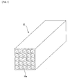
- FIG. 1 is a schematic configuration diagram of the exhaust gas treatment catalyst.
- Fig. 2 is a flowchart showing the procedure of the method of regenerating an exhaust gas treatment catalyst.
- an exhaust gas treatment catalyst 10 is obtained by the following process: catalyst components made of metal oxides such as titanium oxide (TiO 2 ) tungsten oxide (WO 3 ) and vanadium oxide (V 2 O 5 ) are kneaded together with a binder, molded into a honeycomb shape so as to have multiple holes 10a, and calcined.
- metal oxides such as titanium oxide (TiO 2 ) tungsten oxide (WO 3 ) and vanadium oxide (V 2 O 5 ) are kneaded together with a binder, molded into a honeycomb shape so as to have multiple holes 10a, and calcined.
- Such an exhaust gas treatment catalyst 10 is installed in a discharge line for exhaust gas from equipment, such as a coal-fired boiler, for burning coal.
- a reducing agent such as ammonia (NH 3 ) is flowed into the holes 10a together with the exhaust gas to bring the nitrogen oxide (NO x ) in the exhaust gas and the reducing agent into contact with the wall surfaces of the holes 10a. This enables the decomposition and removal of the nitrogen oxide.
- ash generated by burning the coal is continuously flowed into the holes 10a together with exhaust gas.
- components such as calcium (Ca) in the fly ash are gradually adhered (to a thickness of several tens ⁇ m) on the inner wall surfaces of the holes 10a.
- the components inhibit the contact reaction between the nitrogen oxide and the reducing agent on the surfaces of the holes 10a.
- the fly ash itself is partially deposited inside the holes 10a, and gradually makes it hard for exhaust gas to flow into the holes.
- the fly ash completely blocks and clogs the holes, accordingly lowering the denitration performance. For this reason, after a predetermined period of use, the catalyst is taken out from the exhaust gas line and transferred to a regeneration treatment facility.
- a used exhaust gas treatment catalyst 11 transferred to the regeneration treatment facility is introduced into a crushing machine, e.g., a crusher, without a washing treatment step using a washing liquid such as water.
- the catalyst is crushed so that 70 to 95 wt% of the whole exhaust gas treatment catalyst 11 becomes coarse pieces 12 having a size exceeding a threshold size S (any value in a range of 0.105 mm to 1.0 mm) (in Fig. 2 , crushing step SI).
- the fragments obtained by crushing the exhaust gas treatment catalyst 11 are supplied onto a sieve having a mesh size of the threshold size S. Then, the fragments are separated into the coarse pieces 12 having a size exceeding the threshold size S and fine particles 13 having a size not larger than the threshold size S (in Fig. 2 , separating step S2).
- the fine particles 13 passed through the mesh of the sieve are subjected to a disposal treatment. Meanwhile, the coarse pieces 12 left on the mesh of the sieve are introduced into a pulverizing machine, e.g., a hammermill, and pulverized to a fine powder having an average particle diameter of not larger than 0.1 mm (preferably, 70 ⁇ m) (in Fig. 2 , pulverizing step S3).
- a pulverizing machine e.g., a hammermill
- the fine powder is supplied as a raw material together with other ingredients such as a binder and water into a kneading machine, e.g., a kneader, and uniformly kneaded (in Fig. 2 , kneading step S4).
- the kneaded product is supplied into an extruder and molded into a honeycomb shape (in Fig. 2 , molding step S5).
- This molded precursor is naturally dried and subsequently dried with hot air (100°C) or the like (in Fig. 2 , drying step S6). Thereafter, the dried precursor is calcined in a calcining furnace (400 to 600°C) (in Fig. 2 , calcining step S7).
- a regenerated exhaust gas treatment catalyst 14 is obtained.
- the fly ash and so forth are hardly included inside the wall surfaces of the exhaust gas treatment catalyst 14 that is regenerated by kneading, molding, drying, and calcining by use of, as the raw material, the fine powder obtained in the pulverizing step S3 of pulverizing the coarse pieces 12 obtained after the crushing step S1 and the separating step S2.
- the method of regenerating an exhaust gas treatment catalyst according to the present embodiment is capable of regenerating an exhaust gas treatment catalyst in which the lowering of the exhaust-gas treating performance and the oxidation of sulfur dioxide are suppressed.
- the exhaust gas treatment catalyst according to the present embodiment is capable of demonstrating performances that are approximately equivalent to those of a newly-made exhaust gas treatment catalyst.
- the crushing step S1 it is preferable to perform the crushing such that 70 to 95 wt% of the total weight of the used exhaust gas treatment catalyst 11 becomes the coarse pieces 12 as described above. This is because, if the coarse pieces 12 formed by the crushing is less than 70 wt% of the total weight of the used exhaust gas treatment catalyst 11, an excessive amount of the exhaust gas treatment catalyst is disposed of together with the fly ash and so forth. This consequently lowers the regeneration efficiency and increases the regeneration cost. Meanwhile, if the coarse pieces 12 formed by the crushing exceeds 95 wt% of the total weight of the used exhaust gas treatment catalyst 11, the fly ash and so forth may be incorporated into the regenerated exhaust gas treatment catalyst 14 by a large amount.
- the present invention is not limited thereto.
- the prevent invention is also employable in a similar manner to the above-described embodiment.
- the exhaust gas treatment catalyst 10 for denitration contains catalyst components made of metal oxides such as titanium oxide (TiO 2 ), tungsten oxide (WO 3 ), and vanadium oxide (V 2 O 5 ).
- the present invention is not limited thereto. The present invention is employable even to an exhaust gas treatment catalyst for other than denitration which contains a catalyst component made of a different metal oxide, in a similar manner to the above-described embodiment.
- the present invention is not limited thereto. As long as ash in exhaust gas is adhered to and deposited on a surface of an exhaust gas treatment catalyst, the present invention is employable in a similar manner to the above-described embodiment.
- a TiO 2 -WO 3 -V 2 O 5 -based exhaust gas treatment catalyst for denitration having a honeycomb shape (height: 150 mm, breadth: 150 mm, length: 800 mm, wall thickness: 1.15 mm, pitch (distance between the centers of adjacent walls): 7.4 mm, number of meshes (n): 20x20) was used in an exhaust gas line of a coal-fired boiler for approximately 70000 hours (percentage of clogged holes: approximately 3%).
- the catalyst was crushed with a crusher.
- the fragments obtained by crushing were screened with sieves respectively having mesh sizes of 0.074 mm, 0.105 mm, 0.150 mm, 0.212 mm, 0.297 mm, 0.5 mm, and 1.0 mm (the nominal dimensions are specified according to Japanese Industrial Standards (JIS)). Then, the weight percentages and composition percentages of the fine particles passed through the sieves and of the coarse pieces left on the sieves were obtained respectively. Tables 1 and 2 below show the result. Note that, for comparison, the composition percentages of a newly-made exhaust gas treatment catalyst are also shown in Tables 1 and 2 below.
- Catalysts for treating exhaust gas were regenerated by using the coarse pieces screened with the sieves having mesh sizes of 0.5 mm and 0.074 mm, respectively, in Example 1 above. Specifically, each of the coarse pieces was pulverized (to have an average particle diameter of 20 ⁇ m) with a hammermill. The fine powder thus obtained (13 kg), an organic binder (0.9 kg), and water (adequate amount) were kneaded with a kneader and uniformly mixed.
- the obtained kneaded product was supplied into an extruder to prepare a precursor of an exhaust gas treatment catalyst, the catalyst having a honeycomb shape (height: 69 mm, breadth: 69 mm, length: 800 mm, mesh pitch: 7.4 mm, mesh opening: 6.25 mm, number of meshes (n): 9x9).
- the precursor was sufficiently naturally dried and subsequently dried with hot air (100°C ⁇ 5 hours). Thereafter, the dried precursor was subjected to a calcining treatment (500°C x 3 hours) in a calcining furnace, and then cut into pieces (number of meshes: 6x7).
- test samples 1 screened product with the 0.5-mm mesh
- test samples 2 screened product with the 0.074-mm mesh
- the denitration rates and SO 2 oxidation rates of the respective test samples 1 and 2 were obtained, and the As 2 O 3 contents thereof were also obtained.
- the denitration rates and SO 2 oxidation rates thereof were obtained, and the As 2 O 3 contents thereof were also obtained. Table 3 below shows the result. Note that, the denitration rate and the SO 2 oxidation rate were calculated according to equations described below.
- Denitration rate % 1 - NO x concentration at catalyst outlet / NO x concentration at catalyst inlet ⁇ 100
- SO 2 oxidation rate % SO 3 concentration at catalyst outlet - SO 3 concentration at catalyst inlet / SO 2 concentration at catalyst inlet ⁇ 100
- test sample 2 (screened product with the 0.074-mm mesh) and the test sample 3 (product without screening) had improved denitration rates compared with that of the test sample 4 (used product having fly ash adhered thereto), but had greatly increased SO 2 oxidation rates more than those of the test sample 4 (used product having fly ash adhered thereto) and the test sample 5(newly-made product).
- test sample 1 (screened product with the 0.5-mm mesh) had an improved denitration rate compared with that of the test sample 4 (used product having fly ash adhered thereto), and also had a SO 2 oxidation rate suppressed to a level approximately equivalent to that of the test sample 5 (newly-made product).
- the SO 2 oxidation rate of the test sample 1 was satisfactorily reduced compared with those of the test sample 2 (screened product with the 0.074-mm mesh) and the test sample 3 (product without screening).
- test sample 1 (screened product with the 0.5-mm mesh) can be recognized as a regenerated product made of recycled raw material because the test sample 1 contains approximately the same amount of As 2 O 3 , which was originated from the fly ash and so forth, as those of the other test samples 2 to 4.
- test sample 1 demonstrated comparative performances to those of the test sample 5 that was a newly-made product containing no As 2 O 3 .
- the method of regenerating an exhaust gas treatment catalyst according to the present invention is capable of regenerating an exhaust gas treatment catalyst in which the lowering of the exhaust-gas treating performance and the oxidation of sulfur dioxide are suppress. It was also confirmed that the exhaust gas treatment catalyst according to the present invention is capable of demonstrating performances that are approximately equivalent to those of a newly-made exhaust gas treatment catalyst.
- a method of regenerating an exhaust gas treatment catalyst according to the present invention and an exhaust gas treatment catalyst obtained by the method are extremely useful and beneficial in various industries, since such a method and an exhaust gas treatment catalyst are capable of suppressing the lowering of the exhaust-gas treating performance and the oxidation of sulfur dioxide, and demonstrating performances approximately equivalent to those of a newly-made product.
Landscapes
- Chemical & Material Sciences (AREA)
- Engineering & Computer Science (AREA)
- Chemical Kinetics & Catalysis (AREA)
- Materials Engineering (AREA)
- Organic Chemistry (AREA)
- Environmental & Geological Engineering (AREA)
- Biomedical Technology (AREA)
- Analytical Chemistry (AREA)
- General Chemical & Material Sciences (AREA)
- Oil, Petroleum & Natural Gas (AREA)
- Health & Medical Sciences (AREA)
- Life Sciences & Earth Sciences (AREA)
- Sustainable Development (AREA)
- Physics & Mathematics (AREA)
- Thermal Sciences (AREA)
- Catalysts (AREA)
- Exhaust Gas Treatment By Means Of Catalyst (AREA)
Abstract
Description
- The present invention relates to a method of regenerating an exhaust gas treatment catalyst having ash adhered to a surface thereof, and an exhaust gas treatment catalyst obtained by the method. The present invention is extremely effective particularly when employed to regenerate a catalyst for treating exhaust gas from burned coal and removing nitrogen oxide in the exhaust gas.
- A discharge line for exhaust gas from equipment, for example, a coal-fired boiler or the like, in which coal is burnt is provided with an exhaust gas treatment catalyst to treat nitrogen oxide (NOx) in the exhaust gas. Such an exhaust gas treatment catalyst is obtained by the following process: catalyst components made of metal oxides such as titanium oxide (TiO2), tungsten oxide (WO3) and vanadium oxide (V2O5) are kneaded together with a binder, molded into a honeycomb shape so as to have multiple holes, and calcined. A reducing agent such as ammonia (NH3) is flowed into the holes together with the exhaust gas to bring the nitrogen oxide in the exhaust gas and the reducing agent into contact with the wall surfaces of the holes. This enables the decomposition and removal of the nitrogen oxide.
- While such an exhaust gas treatment catalyst is being used, ash (fly ash) generated by burning coal is continuously flowed into the holes together with exhaust gas. Thus, components such as calcium (Ca) in the fly ash are gradually adhered (to a thickness of several tens µm) on the inner wall surfaces of the holes. Such components inhibit the contact reaction between the nitrogen oxide and the reducing agent on the catalyst surface. Additionally, the fly ash itself is partially deposited inside the holes, and gradually makes it hard for exhaust gas to flow into the holes. Eventually, the fly ash completely blocks and clogs the holes, accordingly lowering the denitration performance.
- Against this background, the following proposals have been made for the exhaust gas treatment catalyst used for a predetermined period. For example, such a catalyst is pulverized, molded again, and calcined. Thereby, the aforementioned components in the fly ash that are adhered (to a thickness of several tens µm) on the inner wall surfaces of the holes and the fly ash that is deposited inside the holes are incorporated into the wall surfaces. Moreover, with such a process, fresh surfaces are exposed on the wall surfaces, enabling the reuse of the catalyst (see, for example, Patent Document 1 below and other documents). Meanwhile, after the pulverization, a portion (50 wt% or less) of the catalyst is mixed with a fresh material thereof, molded, and calcined. Thereby, the amounts of the components and the fly ash incorporated into the wall surfaces are reduced, enabling the reuse of the catalyst (see, for example, Patent Document 2 below and other documents).
Patent Document 1:JP-A Sho 60-038037
Patent Document 2:JP-A 2001-340764 - However, such regeneration methods proposed in Patent Documents 1 and 2 and other documents as described above have the following problems.
-
- (1) Since the fly ash and so forth are mixed in the regenerated exhaust gas treatment catalyst, the amounts of the catalyst components per unit volume are reduced. This lowers the denitration performance per unit volume. Particularly, when fly ash is deposited to such an extent that the fly ash blocks and clogs the holes of the catalyst, the catalyst cannot be regenerated to have a sufficient denitration performance by the regeneration method as described above.
- (2) Alkali metal components such as a sodium (Na) component and a potassium (K) component and alkaline earth metal components such as a magnesium (Mg) component and a calcium (Ca) component contained in the fly ash poison the catalyst components. Accordingly, the denitration performance is lowered.
- (3) An iron (Fe) component contained in the fly ash oxidizes sulfur dioxide (SO2) contained in exhaust gas, generating sulfur trioxide (SO3) When sulfur trioxide (SO3) comes into contact with water (H2O) in the exhaust gas, sulfuric acid (H2SO4) is generated. This makes it likely for the exhaust gas line to corrode.
- The present invention has been made in view of the above-described problems. An object of the present invention is to provide a method of regenerating an exhaust gas treatment catalyst, the method being capable of suppressing the lowering of the exhaust-gas treating performance and the oxidation of sulfur dioxide; and an exhaust gas treatment catalyst obtained by the method.
- To solve the above-described problems, a method of regenerating an exhaust gas treatment catalyst according to a first invention provides a method of regenerating an exhaust gas treatment catalyst having ash adhered to a surface thereof, the method characterized by comprising: a crushing step of crushing the exhaust gas treatment catalyst that has been used; a separating step of separating the crushed exhaust gas treatment catalyst into coarse pieces having a size exceeding a threshold size S and fine particles having a size not larger than the threshold size S; a pulverizing step of pulverizing the separated coarse pieces into a fine powder; a molding step of molding the pulverized fine powder as a raw material into an exhaust gas treatment catalyst; and a calcining step of calcining a molded precursor of the exhaust gas treatment catalyst, the method characterized in that the threshold size S has a value not smaller than 0.105 mm.
- A method of regenerating an exhaust gas treatment catalyst according to a second invention provides the method of regenerating an exhaust gas treatment catalyst according to the first invention, characterized in that the crushing step is a step in which the exhaust gas treatment catalyst that has been used is crushed such that 70 to 95 wt% of the whole exhaust gas treatment catalyst that has been used becomes the coarse pieces having a size exceeding the threshold size S.
- A method of regenerating an exhaust gas treatment catalyst according to a third invention provides the method of regenerating an exhaust gas treatment catalyst according to the second invention, characterized in that the threshold size S has a value not larger than 1.0 mm.
- A method of regenerating an exhaust gas treatment catalyst according to a fourth invention provides the method of regenerating an exhaust gas treatment catalyst according to any one of the first to third inventions, characterized in that the pulverizing step is a step in which the coarse pieces is pulverized such that the fine powder has an average particle diameter not larger than 0.1 mm.
- A method of regenerating an exhaust gas treatment catalyst according to a fifth invention provides the method of regenerating an exhaust gas treatment catalyst according to any one of the first to fourth inventions, characterized in that the exhaust gas treatment catalyst is used to treat exhaust gas from a burned coal.
- A method of regenerating an exhaust gas treatment catalyst according to a sixth invention provides the method of regenerating an exhaust gas treatment catalyst according to the fifth invention, characterized in that the exhaust gas treatment catalyst is used to treat nitrogen oxide in the exhaust gas.
- An exhaust gas treatment catalyst according to a seventh invention provides an exhaust gas treatment catalyst characterized by being regenerated by the method of regenerating an exhaust gas treatment catalyst according to any one of the first to sixth inventions.
- In the crushing step of the method of regenerating an exhaust gas treatment catalyst according to the present invention, a large portion of the exhaust gas treatment catalyst itself becomes coarse pieces having a size exceeding the threshold size S. Meanwhile, most of ash adhered to and deposited on the surface of the catalyst becomes fine particles having a size not larger than the threshold size S by impact in the crushing. Accordingly, when the coarse pieces having a size exceeding the threshold size S are separated from the fine particles having a size not larger than the threshold size S in the separating step, most of the ash can be easily removed from the exhaust gas treatment catalyst itself.
- For this reason, ash is hardly included in the exhaust gas treatment catalyst according to the present invention which is regenerated by molding and calcining by use of a fine powder obtained in the pulverizing step in which the coarse pieces are pulverized. Accordingly, the amounts of catalyst components per unit volume can be made approximately the same as those in a newly-made exhaust gas treatment catalyst, and the denitration performance per unit volume can be made approximately equivalent to that of the newly-made exhaust gas treatment catalyst. In addition, the catalyst components can be substantially prevented from being poisoned by the poisonous components, and the lowering of the exhaust-gas treating performance can be greatly suppressed. Simultaneously, the oxidation of sulfur dioxide by the iron component can be substantially eliminated.
- Therefore, the method of regenerating an exhaust gas treatment catalyst according to the present invention is capable of regenerating an exhaust gas treatment catalyst in which the lowering of the exhaust-gas treating performance and the oxidation of sulfur dioxide are suppressed. Thus, the exhaust gas treatment catalyst according to the present invention is capable of demonstrating performances that are approximately equivalent to those of a newly-made exhaust gas treatment catalyst.
-
- [
Fig. 1] Fig. 1 shows a schematic configuration diagram of an exhaust gas treatment catalyst used in a main embodiment of a method of regenerating an exhaust gas treatment catalyst according to the present invention. - [
Fig. 2] Fig. 2 shows a flowchart showing the procedure of the main embodiment of the method of regenerating an exhaust gas treatment catalyst according to the present invention. - A method of regenerating an exhaust gas treatment catalyst according to the present invention and an exhaust gas treatment catalyst obtained by the method will be described on the basis of the drawings. However, the present invention is not limited only to embodiments described below.
- A main embodiment of a method of regenerating an exhaust gas treatment catalyst according to the present invention and an exhaust gas treatment catalyst obtained by the method will be described on the basis of
Figs. 1 and2 .Fig. 1 is a schematic configuration diagram of the exhaust gas treatment catalyst.Fig. 2 is a flowchart showing the procedure of the method of regenerating an exhaust gas treatment catalyst. - As shown in
Fig. 1 , an exhaustgas treatment catalyst 10 according to the present embodiment is obtained by the following process: catalyst components made of metal oxides such as titanium oxide (TiO2) tungsten oxide (WO3) and vanadium oxide (V2O5) are kneaded together with a binder, molded into a honeycomb shape so as to havemultiple holes 10a, and calcined. - Such an exhaust gas treatment catalyst 10 is installed in a discharge line for exhaust gas from equipment, such as a coal-fired boiler, for burning coal. A reducing agent such as ammonia (NH3) is flowed into the
holes 10a together with the exhaust gas to bring the nitrogen oxide (NOx) in the exhaust gas and the reducing agent into contact with the wall surfaces of theholes 10a. This enables the decomposition and removal of the nitrogen oxide. - While the exhaust
gas treatment catalyst 10 is being used, ash (fly ash) generated by burning the coal is continuously flowed into theholes 10a together with exhaust gas. Thus, components such as calcium (Ca) in the fly ash are gradually adhered (to a thickness of several tens µm) on the inner wall surfaces of theholes 10a. The components inhibit the contact reaction between the nitrogen oxide and the reducing agent on the surfaces of theholes 10a. Additionally, the fly ash itself is partially deposited inside theholes 10a, and gradually makes it hard for exhaust gas to flow into the holes. Eventually, the fly ash completely blocks and clogs the holes, accordingly lowering the denitration performance. For this reason, after a predetermined period of use, the catalyst is taken out from the exhaust gas line and transferred to a regeneration treatment facility. - Then, a used exhaust
gas treatment catalyst 11 transferred to the regeneration treatment facility is introduced into a crushing machine, e.g., a crusher, without a washing treatment step using a washing liquid such as water. The catalyst is crushed so that 70 to 95 wt% of the whole exhaustgas treatment catalyst 11 becomescoarse pieces 12 having a size exceeding a threshold size S (any value in a range of 0.105 mm to 1.0 mm) (inFig. 2 , crushing step SI). - The fragments obtained by crushing the exhaust
gas treatment catalyst 11 are supplied onto a sieve having a mesh size of the threshold size S. Then, the fragments are separated into thecoarse pieces 12 having a size exceeding the threshold size S andfine particles 13 having a size not larger than the threshold size S (inFig. 2 , separating step S2). - The
fine particles 13 passed through the mesh of the sieve are subjected to a disposal treatment. Meanwhile, thecoarse pieces 12 left on the mesh of the sieve are introduced into a pulverizing machine, e.g., a hammermill, and pulverized to a fine powder having an average particle diameter of not larger than 0.1 mm (preferably, 70 µm) (inFig. 2 , pulverizing step S3). - Then, the fine powder is supplied as a raw material together with other ingredients such as a binder and water into a kneading machine, e.g., a kneader, and uniformly kneaded (in
Fig. 2 , kneading step S4). The kneaded product is supplied into an extruder and molded into a honeycomb shape (inFig. 2 , molding step S5). This molded precursor is naturally dried and subsequently dried with hot air (100°C) or the like (inFig. 2 , drying step S6). Thereafter, the dried precursor is calcined in a calcining furnace (400 to 600°C) (inFig. 2 , calcining step S7). Thus, a regenerated exhaustgas treatment catalyst 14 is obtained. - Specifically, when the used exhaust
gas treatment catalyst 11 is subjected to the above-described crushing, a large portion (approximately 70 to 95 wt%) of the exhaust gas treatment catalyst itself becomes thecoarse pieces 12 having a size exceeding the size S by the crushing with the crushing machine, e.g., a crusher. Meanwhile, most of the fly ash and so forth adhered to and deposited on the surface of the catalyst become thefine particles 13 having a size not larger than the size S by impact in the crushing with the crushing machine, e.g., a crusher. Accordingly, when the fragments obtained by the crushing are separated into thecoarse pieces 12 having a size exceeding the size S and thefine particles 13 having a size not larger than the size S, most of the fly ash and so forth can be easily removed from the exhaust gas treatment catalyst itself. - For this reason, the fly ash and so forth are hardly included inside the wall surfaces of the exhaust
gas treatment catalyst 14 that is regenerated by kneading, molding, drying, and calcining by use of, as the raw material, the fine powder obtained in the pulverizing step S3 of pulverizing thecoarse pieces 12 obtained after the crushing step S1 and the separating step S2. - As a result, the following effects can be obtained from the regenerated exhaust
gas treatment catalyst 14. -
- (1) The amounts of catalyst components per unit volume can be made approximately the same as those in a newly-made exhaust
gas treatment catalyst 10. This can make the denitration performance per unit volume approximately equivalent to that of the newly-made exhaustgas treatment catalyst 10. - (2) Increases in the amounts of alkali metal components such as a sodium (Na) component and a potassium (K) component and alkaline earth metal components such as a magnesium (Mg) component and a calcium (Ca) component can be suppressed. This makes it possible to substantially prevent the catalyst components from being poisoned by these components, and to greatly suppress the lowering of the denitration performance.
- (3) An increase in an iron (Fe) component can be suppressed. This substantially eliminates the generation of sulfur trioxide (SO3) due to the oxidation of sulfur dioxide (SO2) contained in exhaust gas. It becomes possible to greatly suppress the corrosion of the exhaust gas line by sulfuric acid (H2SO4) generated upon contact between sulfur trioxide (SO3) and water (H2O) in exhaust gas.
- Therefore, the method of regenerating an exhaust gas treatment catalyst according to the present embodiment is capable of regenerating an exhaust gas treatment catalyst in which the lowering of the exhaust-gas treating performance and the oxidation of sulfur dioxide are suppressed. Thus, the exhaust gas treatment catalyst according to the present embodiment is capable of demonstrating performances that are approximately equivalent to those of a newly-made exhaust gas treatment catalyst.
- Moreover, it is possible to remove fly ash and so forth from the used exhaust gas treatment catalyst without a washing treatment step using a washing liquid such as water. This allows a significant reduction in the amount of water disposed of in the regeneration treatment, and the regeneration treatment cost and environmental load can be greatly reduced.
- Note that, in the crushing step S1, it is preferable to perform the crushing such that 70 to 95 wt% of the total weight of the used exhaust
gas treatment catalyst 11 becomes thecoarse pieces 12 as described above. This is because, if thecoarse pieces 12 formed by the crushing is less than 70 wt% of the total weight of the used exhaustgas treatment catalyst 11, an excessive amount of the exhaust gas treatment catalyst is disposed of together with the fly ash and so forth. This consequently lowers the regeneration efficiency and increases the regeneration cost. Meanwhile, if thecoarse pieces 12 formed by the crushing exceeds 95 wt% of the total weight of the used exhaustgas treatment catalyst 11, the fly ash and so forth may be incorporated into the regenerated exhaustgas treatment catalyst 14 by a large amount. - Note that, in the above-described embodiment, the description has been given of the case where the exhaust
gas treatment catalyst 10 is molded into a honeycomb shape. However, the present invention is not limited thereto. As to other embodiments, in the case of an exhaust gas treatment catalyst molded into, for example, a pellet shape, pipe shape, or other shape, the prevent invention is also employable in a similar manner to the above-described embodiment. - Moreover, in the above-described embodiment, the description has been given of the case where the exhaust
gas treatment catalyst 10 for denitration contains catalyst components made of metal oxides such as titanium oxide (TiO2), tungsten oxide (WO3), and vanadium oxide (V2O5). However, the present invention is not limited thereto. The present invention is employable even to an exhaust gas treatment catalyst for other than denitration which contains a catalyst component made of a different metal oxide, in a similar manner to the above-described embodiment. - Furthermore, in the above-described embodiment, the description has been given of the case where the exhaust
gas treatment catalyst 10 is installed in the discharge line for exhaust gas from equipment, such as a coal-fired boiler, for burning coal. However, the present invention is not limited thereto. As long as ash in exhaust gas is adhered to and deposited on a surface of an exhaust gas treatment catalyst, the present invention is employable in a similar manner to the above-described embodiment. - Hereinafter, description will be given of a confirmation test to confirm the effects of the method of regenerating an exhaust gas treatment catalyst according to the present invention and the exhaust gas treatment catalyst obtained by the method. However, the present invention is not limited only to the confirmation test described below.
- A TiO2-WO3-V2O5-based exhaust gas treatment catalyst for denitration having a honeycomb shape (height: 150 mm, breadth: 150 mm, length: 800 mm, wall thickness: 1.15 mm, pitch (distance between the centers of adjacent walls): 7.4 mm, number of meshes (n): 20x20) was used in an exhaust gas line of a coal-fired boiler for approximately 70000 hours (percentage of clogged holes: approximately 3%). The catalyst was crushed with a crusher. The fragments obtained by crushing were screened with sieves respectively having mesh sizes of 0.074 mm, 0.105 mm, 0.150 mm, 0.212 mm, 0.297 mm, 0.5 mm, and 1.0 mm (the nominal dimensions are specified according to Japanese Industrial Standards (JIS)). Then, the weight percentages and composition percentages of the fine particles passed through the sieves and of the coarse pieces left on the sieves were obtained respectively. Tables 1 and 2 below show the result. Note that, for comparison, the composition percentages of a newly-made exhaust gas treatment catalyst are also shown in Tables 1 and 2 below.
-

-


- As seen from Tables 1 and 2 above, it was confirmed that the mesh sizes (threshold size S) set in a range of 0.105 to 1.0 mm were able to make the weight percentage of the coarse pieces in a range of 70 to 95%.
- Catalysts for treating exhaust gas were regenerated by using the coarse pieces screened with the sieves having mesh sizes of 0.5 mm and 0.074 mm, respectively, in Example 1 above. Specifically, each of the coarse pieces was pulverized (to have an average particle diameter of 20 µm) with a hammermill. The fine powder thus obtained (13 kg), an organic binder (0.9 kg), and water (adequate amount) were kneaded with a kneader and uniformly mixed. The obtained kneaded product was supplied into an extruder to prepare a precursor of an exhaust gas treatment catalyst, the catalyst having a honeycomb shape (height: 69 mm, breadth: 69 mm, length: 800 mm, mesh pitch: 7.4 mm, mesh opening: 6.25 mm, number of meshes (n): 9x9). The precursor was sufficiently naturally dried and subsequently dried with hot air (100°C × 5 hours). Thereafter, the dried precursor was subjected to a calcining treatment (500°C x 3 hours) in a calcining furnace, and then cut into pieces (number of meshes: 6x7). In this manner, obtained were test samples 1 (screened product with the 0.5-mm mesh) and test samples 2 (screened product with the 0.074-mm mesh) of the regenerated exhaust gas treatment catalyst (two in each test sample).
- Subsequently, under conditions described below, the denitration rates and SO2 oxidation rates of the respective test samples 1 and 2 were obtained, and the As2O3 contents thereof were also obtained. Moreover, for comparison, prepared were: an exhaust gas treatment catalyst (test sample 3) regenerated under the same conditions as those of the test samples 1 and 2 after mixing coarse pieces obtained under the conditions of the Example 1, except the omission of the screening (separation step), i.e., without removing fly ash; an exhaust gas treatment catalyst (test sample 4) before the regeneration treatment; and a newly-made exhaust gas treatment catalyst (test sample 5). The denitration rates and SO2 oxidation rates thereof were obtained, and the As2O3 contents thereof were also obtained. Table 3 below shows the result. Note that, the denitration rate and the SO2 oxidation rate were calculated according to equations described below.
-
- · Compositions of exhaust gas- NOx: 150 ppm
NH3: 150 ppm
SO2: 800 ppm
O2: 4%
CO2: approximately 12.5% H2O: approximately 11.5%
N2: balance - · Temperature of exhaust gas: 380°C
- · Amount of exhaust gas: 19.97 Nm3/hr
- · Ugs: 2.3 Nm/sec
- · AV: 11.63 N3/m2·hr
-


-
[Table 3] Test sample Denitration rate (%) SO2 oxidation rate (%) As2O3 (%) 1 95.8 0.95 0.36 2 95.0 1.16 0.37 3 94.4 1.37 0.36 4 83.5 0.84 0.37 b 96.2 0.93 0.00 - As seen from Table 3 above, the test sample 2 (screened product with the 0.074-mm mesh) and the test sample 3 (product without screening) had improved denitration rates compared with that of the test sample 4 (used product having fly ash adhered thereto), but had greatly increased SO2 oxidation rates more than those of the test sample 4 (used product having fly ash adhered thereto) and the test sample 5(newly-made product).
- In contrast, the test sample 1 (screened product with the 0.5-mm mesh) had an improved denitration rate compared with that of the test sample 4 (used product having fly ash adhered thereto), and also had a SO2 oxidation rate suppressed to a level approximately equivalent to that of the test sample 5 (newly-made product). The SO2 oxidation rate of the test sample 1 was satisfactorily reduced compared with those of the test sample 2 (screened product with the 0.074-mm mesh) and the test sample 3 (product without screening).
- Moreover, the test sample 1 (screened product with the 0.5-mm mesh) can be recognized as a regenerated product made of recycled raw material because the test sample 1 contains approximately the same amount of As2O3, which was originated from the fly ash and so forth, as those of the other test samples 2 to 4. However, the test sample 1 demonstrated comparative performances to those of the
test sample 5 that was a newly-made product containing no As2O3. - From the results described above, it was confirmed that the method of regenerating an exhaust gas treatment catalyst according to the present invention is capable of regenerating an exhaust gas treatment catalyst in which the lowering of the exhaust-gas treating performance and the oxidation of sulfur dioxide are suppress. It was also confirmed that the exhaust gas treatment catalyst according to the present invention is capable of demonstrating performances that are approximately equivalent to those of a newly-made exhaust gas treatment catalyst.
- A method of regenerating an exhaust gas treatment catalyst according to the present invention and an exhaust gas treatment catalyst obtained by the method are extremely useful and beneficial in various industries, since such a method and an exhaust gas treatment catalyst are capable of suppressing the lowering of the exhaust-gas treating performance and the oxidation of sulfur dioxide, and demonstrating performances approximately equivalent to those of a newly-made product.
Claims (7)
- A method of regenerating an exhaust gas treatment catalyst (11) having ash adhered to a surface thereof, the method characterized by comprising:a crushing step (S1) of crushing the exhaust gas treatment catalyst (11) that has been used;a separating step (S2) of separating the crushed exhaust gas treatment catalyst (11) into coarse pieces (12) having a size exceeding a threshold size (S) and fine particles (13) having a size not larger than the threshold size (S);a pulverizing step (S3) of pulverizing the separated coarse pieces (12) into a fine powder;a molding step (S5) of molding the pulverized fine powder as a raw material into an exhaust gas treatment catalyst; anda calcining step (S7) of calcining a molded precursor of the exhaust gas treatment catalyst,the method characterized in that the threshold size (S) has a value not smaller than 0.105 mm.
- The method of regenerating an exhaust gas treatment catalyst (11) according to claim 1, characterized in that
the crushing step (S1) is a step in which the exhaust gas treatment catalyst (11) that has been used is crushed such that 70 to 95 wt% of the whole exhaust gas treatment catalyst that has been used becomes the coarse pieces (12) having a size exceeding the threshold size (S). - The method of regenerating an exhaust gas treatment catalyst (11) according to claim 2, characterized in that
the threshold size (S) has a value not larger than 1.0 mm. - The method of regenerating an exhaust gas treatment catalyst (11) according to any one of claims 1 to 3, characterized in that the pulverizing step (S3) is a step in which the coarse pieces (12) are pulverized such that the fine powder has an average particle diameter not larger than 0.1 mm.
- The method of regenerating an exhaust gas treatment catalyst (11) according to any one of claims 1 to 4, characterized in that
the exhaust gas treatment catalyst is used to treat exhaust gas from a burned coal. - The method of regenerating an exhaust gas treatment catalyst (11) according to claim 5, characterized in that
the exhaust gas treatment catalyst is used to treat nitrogen oxide in the exhaust gas. - An exhaust gas treatment catalyst (11) characterized by being regenerated by the method of regenerating an exhaust gas treatment catalyst according to any one of claims 1 to 6.
Applications Claiming Priority (3)
| Application Number | Priority Date | Filing Date | Title |
|---|---|---|---|
| JP2008049133 | 2008-02-29 | ||
| JP2008175157A JP5308083B2 (en) | 2008-02-29 | 2008-07-04 | Exhaust gas treatment catalyst regeneration method and exhaust gas treatment catalyst using this method |
| PCT/JP2008/069428 WO2009107276A1 (en) | 2008-02-29 | 2008-10-27 | Method of regenerating catalyst for discharge gas treatment and catalyst for discharge gas treatment obtained by the method |
Publications (3)
| Publication Number | Publication Date |
|---|---|
| EP2248584A1 true EP2248584A1 (en) | 2010-11-10 |
| EP2248584A4 EP2248584A4 (en) | 2011-09-14 |
| EP2248584B1 EP2248584B1 (en) | 2018-02-28 |
Family
ID=41015685
Family Applications (1)
| Application Number | Title | Priority Date | Filing Date |
|---|---|---|---|
| EP08873002.3A Active EP2248584B1 (en) | 2008-02-29 | 2008-10-27 | Method of regenerating catalyst for discharge gas treatment |
Country Status (10)
| Country | Link |
|---|---|
| US (1) | US8785341B2 (en) |
| EP (1) | EP2248584B1 (en) |
| JP (1) | JP5308083B2 (en) |
| KR (1) | KR101190898B1 (en) |
| CN (1) | CN101878066B (en) |
| BR (1) | BRPI0819459A8 (en) |
| CA (1) | CA2706530C (en) |
| DK (1) | DK2248584T3 (en) |
| RU (1) | RU2436628C1 (en) |
| WO (1) | WO2009107276A1 (en) |
Families Citing this family (13)
| Publication number | Priority date | Publication date | Assignee | Title |
|---|---|---|---|---|
| US7020482B2 (en) | 2002-01-23 | 2006-03-28 | Qualcomm Incorporated | Reallocation of excess power for full channel-state information (CSI) multiple-input, multiple-output (MIMO) systems |
| JP5357974B2 (en) | 2009-10-01 | 2013-12-04 | 三菱重工業株式会社 | Mercury oxidation catalyst and method for producing the same |
| JP5374441B2 (en) * | 2010-05-18 | 2013-12-25 | 三菱重工業株式会社 | Exhaust gas treatment catalyst regeneration method and exhaust gas treatment catalyst using this method |
| JP5535769B2 (en) * | 2010-06-02 | 2014-07-02 | 三菱重工業株式会社 | Exhaust gas treatment catalyst regeneration method and exhaust gas treatment catalyst using this method |
| KR101246271B1 (en) * | 2011-03-22 | 2013-03-21 | 주식회사 나노 | Method of recycling waste denitrification catalyst |
| US9114391B2 (en) | 2011-03-29 | 2015-08-25 | Mitsubishi Hitachi Power Systems, Ltd. | Method for removing arsenic compound, method for regenerating NOx removal catalyst, and NOx removal catalyst |
| JP5812768B2 (en) | 2011-08-31 | 2015-11-17 | 三菱日立パワーシステムズ株式会社 | Denitration catalyst regeneration method and heavy oil-fired combustion device operation method |
| JP6174353B2 (en) * | 2013-03-29 | 2017-08-02 | 日本碍子株式会社 | Honeycomb structure and exhaust gas purification device |
| CN103418446A (en) * | 2013-07-25 | 2013-12-04 | 苏州华乐大气污染控制科技发展有限公司 | Pore recovery agent used in SCR (Selective Catalytic Reduction) denitration catalyst regeneration process and pore recovery agent preparation method |
| JP6441140B2 (en) * | 2014-03-28 | 2018-12-19 | 日揮触媒化成株式会社 | Method for producing titanium oxide fine powder using spent catalyst and method for producing exhaust gas treatment catalyst using the powder |
| CN104857949A (en) * | 2015-04-24 | 2015-08-26 | 江苏龙源催化剂有限公司 | Indirect regeneration denitration catalyst and preparation method thereof |
| CN110538569A (en) * | 2019-09-25 | 2019-12-06 | 湖南碧德环保科技有限公司 | Flue gas dry-process denitration agent and preparation method thereof |
| AU2023288272B2 (en) * | 2022-06-20 | 2026-06-11 | Ngk Insulators, Ltd. | Regeneration method for acidic gas adsorption device, and manufacturing method for acidic gas adsorption device |
Family Cites Families (16)
| Publication number | Priority date | Publication date | Assignee | Title |
|---|---|---|---|---|
| BE754510A (en) | 1969-08-12 | 1971-01-18 | Nickel Le | REGENERATION OF NICKEL-BASED CATALYSTS |
| JPS6038037A (en) * | 1983-08-11 | 1985-02-27 | Nippon Shokubai Kagaku Kogyo Co Ltd | Regeneration of denitrification catalyst |
| US4755282A (en) | 1987-07-22 | 1988-07-05 | Shell Oil Company | Process for the reduction of NH3 in regeneration zone off gas by select recycle of certain-sized NH3 decomposition catalysts |
| RU2085806C1 (en) * | 1991-06-06 | 1997-07-27 | Шоппе Фритц | Method and device for better use heat from combustion products |
| US5324341A (en) * | 1992-05-05 | 1994-06-28 | Molten Metal Technology, Inc. | Method for chemically reducing metals in waste compositions |
| EP0604826A1 (en) * | 1992-12-24 | 1994-07-06 | Balaton Holding Sa | Installation and process for the valorization of combustible materials especially industrial wastes and domestic waste |
| DE69423857T2 (en) | 1993-12-17 | 2000-11-09 | Matsushita Electric Industrial Co., Ltd. | Method and device for cleaning exhaust gas |
| JP3655188B2 (en) | 1999-11-09 | 2005-06-02 | クマクラ工業株式会社 | Magnetized material separation and recovery system |
| JP4578624B2 (en) * | 2000-06-02 | 2010-11-10 | 株式会社日本触媒 | Method for producing exhaust gas treatment catalyst |
| JP4109541B2 (en) | 2000-06-08 | 2008-07-02 | 株式会社ジャパンエナジー | Method for producing catalyst and method for recovering metal used for hydrorefining |
| AU2001273331A1 (en) * | 2000-07-07 | 2002-01-21 | Symyx Technologies, Inc. | Methods and apparatus for mechanical treatment of materials such as catalysts |
| US6800585B2 (en) * | 2001-02-13 | 2004-10-05 | Sk Corporation | Catalyst for selective catalytic reduction of nitrogen oxides and a method for preparing the same |
| JP4296020B2 (en) * | 2002-04-12 | 2009-07-15 | 三菱化学株式会社 | Regeneration method of deteriorated catalyst |
| JP2004275852A (en) * | 2003-03-14 | 2004-10-07 | Mitsubishi Heavy Ind Ltd | Flue gas denitration catalyst and method for producing the same |
| JP2005126317A (en) * | 2003-09-30 | 2005-05-19 | Ngk Insulators Ltd | Method for manufacturing honeycomb structure and honeycomb structure |
| US7132066B2 (en) | 2003-09-30 | 2006-11-07 | Ngk Insulators, Ltd. | Method for producing honeycomb structure and honeycomb structure |
-
2008
- 2008-07-04 JP JP2008175157A patent/JP5308083B2/en active Active
- 2008-10-27 EP EP08873002.3A patent/EP2248584B1/en active Active
- 2008-10-27 US US12/743,514 patent/US8785341B2/en active Active
- 2008-10-27 DK DK08873002.3T patent/DK2248584T3/en active
- 2008-10-27 CN CN2008801182550A patent/CN101878066B/en active Active
- 2008-10-27 BR BRPI0819459A patent/BRPI0819459A8/en active Search and Examination
- 2008-10-27 RU RU2010121868/04A patent/RU2436628C1/en not_active IP Right Cessation
- 2008-10-27 CA CA2706530A patent/CA2706530C/en not_active Expired - Fee Related
- 2008-10-27 KR KR1020107011750A patent/KR101190898B1/en active Active
- 2008-10-27 WO PCT/JP2008/069428 patent/WO2009107276A1/en not_active Ceased
Also Published As
| Publication number | Publication date |
|---|---|
| US20100292070A1 (en) | 2010-11-18 |
| DK2248584T3 (en) | 2018-04-30 |
| BRPI0819459A8 (en) | 2017-07-04 |
| CN101878066B (en) | 2013-03-20 |
| WO2009107276A1 (en) | 2009-09-03 |
| EP2248584B1 (en) | 2018-02-28 |
| KR101190898B1 (en) | 2012-10-12 |
| JP5308083B2 (en) | 2013-10-09 |
| EP2248584A4 (en) | 2011-09-14 |
| RU2436628C1 (en) | 2011-12-20 |
| BRPI0819459A2 (en) | 2015-05-05 |
| CN101878066A (en) | 2010-11-03 |
| CA2706530C (en) | 2012-10-16 |
| US8785341B2 (en) | 2014-07-22 |
| CA2706530A1 (en) | 2009-09-03 |
| JP2009226388A (en) | 2009-10-08 |
| KR20100077041A (en) | 2010-07-06 |
Similar Documents
| Publication | Publication Date | Title |
|---|---|---|
| EP2248584B1 (en) | Method of regenerating catalyst for discharge gas treatment | |
| US7666808B2 (en) | Denitrification catalyst regeneration method | |
| EP3137637B1 (en) | Methods for reprocessing used catalysts | |
| JP5612886B2 (en) | Exhaust gas treatment apparatus and exhaust gas treatment method using the same | |
| KR920005938B1 (en) | Catalyst for the reduction of nitrogen oxides a method for its preparation and the use thereof | |
| KR101246271B1 (en) | Method of recycling waste denitrification catalyst | |
| EP2578314B1 (en) | Method for regeneration of exhaust gas treatment catalyst, and exhaust gas treatment catalyst produced using the method | |
| JP4860077B2 (en) | Process for producing catalyst for selective catalytic reduction of nitrogen oxides at high temperature | |
| JP5374441B2 (en) | Exhaust gas treatment catalyst regeneration method and exhaust gas treatment catalyst using this method | |
| JP4578624B2 (en) | Method for producing exhaust gas treatment catalyst | |
| JP4177661B2 (en) | Method for producing exhaust gas treatment catalyst | |
| JPS61153139A (en) | Regeneration method of denitrating catalyst | |
| JP4084658B2 (en) | Method for producing exhaust gas treatment catalyst | |
| KR20190124479A (en) | A Method for Manufacturing SCR Catalyst Using Waste SCR Catalyst | |
| DE60223947T2 (en) | METHOD FOR REMOVING NITRIC OXIDES FROM EXHAUST GASES FROM A CATALYTIC SWITCHING LAYER REACTOR | |
| JP2001187318A (en) | Exhaust gas treatment method and catalyst-carrying ceramic filter |
Legal Events
| Date | Code | Title | Description |
|---|---|---|---|
| PUAI | Public reference made under article 153(3) epc to a published international application that has entered the european phase |
Free format text: ORIGINAL CODE: 0009012 |
|
| 17P | Request for examination filed |
Effective date: 20100528 |
|
| AK | Designated contracting states |
Kind code of ref document: A1 Designated state(s): AT BE BG CH CY CZ DE DK EE ES FI FR GB GR HR HU IE IS IT LI LT LU LV MC MT NL NO PL PT RO SE SI SK TR |
|
| AX | Request for extension of the european patent |
Extension state: AL BA MK RS |
|
| DAX | Request for extension of the european patent (deleted) | ||
| A4 | Supplementary search report drawn up and despatched |
Effective date: 20110818 |
|
| RIC1 | Information provided on ipc code assigned before grant |
Ipc: B01D 53/96 20060101ALI20110805BHEP Ipc: B01J 38/00 20060101ALI20110805BHEP Ipc: B01J 23/92 20060101AFI20110805BHEP Ipc: B01D 53/94 20060101ALI20110805BHEP |
|
| 17Q | First examination report despatched |
Effective date: 20130411 |
|
| RAP1 | Party data changed (applicant data changed or rights of an application transferred) |
Owner name: MITSUBISHI HITACHI POWER SYSTEMS, LTD. |
|
| GRAP | Despatch of communication of intention to grant a patent |
Free format text: ORIGINAL CODE: EPIDOSNIGR1 |
|
| INTG | Intention to grant announced |
Effective date: 20170622 |
|
| GRAJ | Information related to disapproval of communication of intention to grant by the applicant or resumption of examination proceedings by the epo deleted |
Free format text: ORIGINAL CODE: EPIDOSDIGR1 |
|
| GRAS | Grant fee paid |
Free format text: ORIGINAL CODE: EPIDOSNIGR3 |
|
| INTG | Intention to grant announced |
Effective date: 20170622 |
|
| GRAJ | Information related to disapproval of communication of intention to grant by the applicant or resumption of examination proceedings by the epo deleted |
Free format text: ORIGINAL CODE: EPIDOSDIGR1 |
|
| GRAL | Information related to payment of fee for publishing/printing deleted |
Free format text: ORIGINAL CODE: EPIDOSDIGR3 |
|
| INTC | Intention to grant announced (deleted) | ||
| GRAR | Information related to intention to grant a patent recorded |
Free format text: ORIGINAL CODE: EPIDOSNIGR71 |
|
| GRAA | (expected) grant |
Free format text: ORIGINAL CODE: 0009210 |
|
| AK | Designated contracting states |
Kind code of ref document: B1 Designated state(s): AT BE BG CH CY CZ DE DK EE ES FI FR GB GR HR HU IE IS IT LI LT LU LV MC MT NL NO PL PT RO SE SI SK TR |
|
| INTG | Intention to grant announced |
Effective date: 20180123 |
|
| REG | Reference to a national code |
Ref country code: GB Ref legal event code: FG4D Ref country code: CH Ref legal event code: EP |
|
| REG | Reference to a national code |
Ref country code: AT Ref legal event code: REF Ref document number: 973535 Country of ref document: AT Kind code of ref document: T Effective date: 20180315 |
|
| REG | Reference to a national code |
Ref country code: IE Ref legal event code: FG4D |
|
| REG | Reference to a national code |
Ref country code: DE Ref legal event code: R096 Ref document number: 602008054262 Country of ref document: DE |
|
| REG | Reference to a national code |
Ref country code: DK Ref legal event code: T3 Effective date: 20180423 |
|
| REG | Reference to a national code |
Ref country code: NL Ref legal event code: MP Effective date: 20180228 |
|
| REG | Reference to a national code |
Ref country code: LT Ref legal event code: MG4D |
|
| PG25 | Lapsed in a contracting state [announced via postgrant information from national office to epo] |
Ref country code: HR Free format text: LAPSE BECAUSE OF FAILURE TO SUBMIT A TRANSLATION OF THE DESCRIPTION OR TO PAY THE FEE WITHIN THE PRESCRIBED TIME-LIMIT Effective date: 20180228 Ref country code: NL Free format text: LAPSE BECAUSE OF FAILURE TO SUBMIT A TRANSLATION OF THE DESCRIPTION OR TO PAY THE FEE WITHIN THE PRESCRIBED TIME-LIMIT Effective date: 20180228 Ref country code: CY Free format text: LAPSE BECAUSE OF FAILURE TO SUBMIT A TRANSLATION OF THE DESCRIPTION OR TO PAY THE FEE WITHIN THE PRESCRIBED TIME-LIMIT Effective date: 20180228 Ref country code: LT Free format text: LAPSE BECAUSE OF FAILURE TO SUBMIT A TRANSLATION OF THE DESCRIPTION OR TO PAY THE FEE WITHIN THE PRESCRIBED TIME-LIMIT Effective date: 20180228 Ref country code: ES Free format text: LAPSE BECAUSE OF FAILURE TO SUBMIT A TRANSLATION OF THE DESCRIPTION OR TO PAY THE FEE WITHIN THE PRESCRIBED TIME-LIMIT Effective date: 20180228 Ref country code: NO Free format text: LAPSE BECAUSE OF FAILURE TO SUBMIT A TRANSLATION OF THE DESCRIPTION OR TO PAY THE FEE WITHIN THE PRESCRIBED TIME-LIMIT Effective date: 20180528 Ref country code: FI Free format text: LAPSE BECAUSE OF FAILURE TO SUBMIT A TRANSLATION OF THE DESCRIPTION OR TO PAY THE FEE WITHIN THE PRESCRIBED TIME-LIMIT Effective date: 20180228 |
|
| PG25 | Lapsed in a contracting state [announced via postgrant information from national office to epo] |
Ref country code: LV Free format text: LAPSE BECAUSE OF FAILURE TO SUBMIT A TRANSLATION OF THE DESCRIPTION OR TO PAY THE FEE WITHIN THE PRESCRIBED TIME-LIMIT Effective date: 20180228 Ref country code: SE Free format text: LAPSE BECAUSE OF FAILURE TO SUBMIT A TRANSLATION OF THE DESCRIPTION OR TO PAY THE FEE WITHIN THE PRESCRIBED TIME-LIMIT Effective date: 20180228 Ref country code: GR Free format text: LAPSE BECAUSE OF FAILURE TO SUBMIT A TRANSLATION OF THE DESCRIPTION OR TO PAY THE FEE WITHIN THE PRESCRIBED TIME-LIMIT Effective date: 20180529 Ref country code: BG Free format text: LAPSE BECAUSE OF FAILURE TO SUBMIT A TRANSLATION OF THE DESCRIPTION OR TO PAY THE FEE WITHIN THE PRESCRIBED TIME-LIMIT Effective date: 20180528 |
|
| PG25 | Lapsed in a contracting state [announced via postgrant information from national office to epo] |
Ref country code: EE Free format text: LAPSE BECAUSE OF FAILURE TO SUBMIT A TRANSLATION OF THE DESCRIPTION OR TO PAY THE FEE WITHIN THE PRESCRIBED TIME-LIMIT Effective date: 20180228 Ref country code: PL Free format text: LAPSE BECAUSE OF FAILURE TO SUBMIT A TRANSLATION OF THE DESCRIPTION OR TO PAY THE FEE WITHIN THE PRESCRIBED TIME-LIMIT Effective date: 20180228 Ref country code: RO Free format text: LAPSE BECAUSE OF FAILURE TO SUBMIT A TRANSLATION OF THE DESCRIPTION OR TO PAY THE FEE WITHIN THE PRESCRIBED TIME-LIMIT Effective date: 20180228 Ref country code: IT Free format text: LAPSE BECAUSE OF FAILURE TO SUBMIT A TRANSLATION OF THE DESCRIPTION OR TO PAY THE FEE WITHIN THE PRESCRIBED TIME-LIMIT Effective date: 20180228 |
|
| REG | Reference to a national code |
Ref country code: DE Ref legal event code: R097 Ref document number: 602008054262 Country of ref document: DE |
|
| PG25 | Lapsed in a contracting state [announced via postgrant information from national office to epo] |
Ref country code: CZ Free format text: LAPSE BECAUSE OF FAILURE TO SUBMIT A TRANSLATION OF THE DESCRIPTION OR TO PAY THE FEE WITHIN THE PRESCRIBED TIME-LIMIT Effective date: 20180228 Ref country code: SK Free format text: LAPSE BECAUSE OF FAILURE TO SUBMIT A TRANSLATION OF THE DESCRIPTION OR TO PAY THE FEE WITHIN THE PRESCRIBED TIME-LIMIT Effective date: 20180228 |
|
| PLBE | No opposition filed within time limit |
Free format text: ORIGINAL CODE: 0009261 |
|
| STAA | Information on the status of an ep patent application or granted ep patent |
Free format text: STATUS: NO OPPOSITION FILED WITHIN TIME LIMIT |
|
| 26N | No opposition filed |
Effective date: 20181129 |
|
| PG25 | Lapsed in a contracting state [announced via postgrant information from national office to epo] |
Ref country code: SI Free format text: LAPSE BECAUSE OF FAILURE TO SUBMIT A TRANSLATION OF THE DESCRIPTION OR TO PAY THE FEE WITHIN THE PRESCRIBED TIME-LIMIT Effective date: 20180228 |
|
| REG | Reference to a national code |
Ref country code: CH Ref legal event code: PL |
|
| GBPC | Gb: european patent ceased through non-payment of renewal fee |
Effective date: 20181027 |
|
| REG | Reference to a national code |
Ref country code: BE Ref legal event code: MM Effective date: 20181031 |
|
| PG25 | Lapsed in a contracting state [announced via postgrant information from national office to epo] |
Ref country code: MC Free format text: LAPSE BECAUSE OF FAILURE TO SUBMIT A TRANSLATION OF THE DESCRIPTION OR TO PAY THE FEE WITHIN THE PRESCRIBED TIME-LIMIT Effective date: 20180228 Ref country code: LU Free format text: LAPSE BECAUSE OF NON-PAYMENT OF DUE FEES Effective date: 20181027 |
|
| REG | Reference to a national code |
Ref country code: IE Ref legal event code: MM4A |
|
| PG25 | Lapsed in a contracting state [announced via postgrant information from national office to epo] |
Ref country code: BE Free format text: LAPSE BECAUSE OF NON-PAYMENT OF DUE FEES Effective date: 20181031 Ref country code: FR Free format text: LAPSE BECAUSE OF NON-PAYMENT OF DUE FEES Effective date: 20181031 Ref country code: CH Free format text: LAPSE BECAUSE OF NON-PAYMENT OF DUE FEES Effective date: 20181031 Ref country code: LI Free format text: LAPSE BECAUSE OF NON-PAYMENT OF DUE FEES Effective date: 20181031 |
|
| PG25 | Lapsed in a contracting state [announced via postgrant information from national office to epo] |
Ref country code: GB Free format text: LAPSE BECAUSE OF NON-PAYMENT OF DUE FEES Effective date: 20181027 Ref country code: IE Free format text: LAPSE BECAUSE OF NON-PAYMENT OF DUE FEES Effective date: 20181027 |
|
| PG25 | Lapsed in a contracting state [announced via postgrant information from national office to epo] |
Ref country code: MT Free format text: LAPSE BECAUSE OF NON-PAYMENT OF DUE FEES Effective date: 20181027 |
|
| PGFP | Annual fee paid to national office [announced via postgrant information from national office to epo] |
Ref country code: DK Payment date: 20191010 Year of fee payment: 12 |
|
| PG25 | Lapsed in a contracting state [announced via postgrant information from national office to epo] |
Ref country code: TR Free format text: LAPSE BECAUSE OF FAILURE TO SUBMIT A TRANSLATION OF THE DESCRIPTION OR TO PAY THE FEE WITHIN THE PRESCRIBED TIME-LIMIT Effective date: 20180228 |
|
| PG25 | Lapsed in a contracting state [announced via postgrant information from national office to epo] |
Ref country code: PT Free format text: LAPSE BECAUSE OF FAILURE TO SUBMIT A TRANSLATION OF THE DESCRIPTION OR TO PAY THE FEE WITHIN THE PRESCRIBED TIME-LIMIT Effective date: 20180228 |
|
| PG25 | Lapsed in a contracting state [announced via postgrant information from national office to epo] |
Ref country code: HU Free format text: LAPSE BECAUSE OF FAILURE TO SUBMIT A TRANSLATION OF THE DESCRIPTION OR TO PAY THE FEE WITHIN THE PRESCRIBED TIME-LIMIT; INVALID AB INITIO Effective date: 20081027 |
|
| PG25 | Lapsed in a contracting state [announced via postgrant information from national office to epo] |
Ref country code: IS Free format text: LAPSE BECAUSE OF FAILURE TO SUBMIT A TRANSLATION OF THE DESCRIPTION OR TO PAY THE FEE WITHIN THE PRESCRIBED TIME-LIMIT Effective date: 20180628 |
|
| REG | Reference to a national code |
Ref country code: DE Ref legal event code: R082 Ref document number: 602008054262 Country of ref document: DE Representative=s name: CBDL PATENTANWAELTE, DE Ref country code: DE Ref legal event code: R081 Ref document number: 602008054262 Country of ref document: DE Owner name: MITSUBISHI POWER, LTD., YOKOHAMA-SHI, JP Free format text: FORMER OWNER: MITSUBISHI HITACHI POWER SYSTEMS, LTD., YOKOHAMA-SHI, KANAGAWA, JP |
|
| REG | Reference to a national code |
Ref country code: AT Ref legal event code: HC Ref document number: 973535 Country of ref document: AT Kind code of ref document: T Owner name: MITSUBISHI POWER, LTD., JP Effective date: 20210407 |
|
| REG | Reference to a national code |
Ref country code: DK Ref legal event code: EBP Effective date: 20201031 |
|
| PG25 | Lapsed in a contracting state [announced via postgrant information from national office to epo] |
Ref country code: DK Free format text: LAPSE BECAUSE OF NON-PAYMENT OF DUE FEES Effective date: 20201031 |
|
| REG | Reference to a national code |
Ref country code: AT Ref legal event code: UEP Ref document number: 973535 Country of ref document: AT Kind code of ref document: T Effective date: 20180228 |
|
| REG | Reference to a national code |
Ref country code: DE Ref legal event code: R082 Ref document number: 602008054262 Country of ref document: DE Representative=s name: CBDL PATENTANWAELTE GBR, DE Ref country code: DE Ref legal event code: R082 Ref document number: 602008054262 Country of ref document: DE Representative=s name: CBDL PATENTANWAELTE EGBR, DE |
|
| PGFP | Annual fee paid to national office [announced via postgrant information from national office to epo] |
Ref country code: DE Payment date: 20250902 Year of fee payment: 18 |
|
| PGFP | Annual fee paid to national office [announced via postgrant information from national office to epo] |
Ref country code: AT Payment date: 20250925 Year of fee payment: 18 |