EP2248276B1 - Vorkodierung für mehrfachantennen - Google Patents
Vorkodierung für mehrfachantennen Download PDFInfo
- Publication number
- EP2248276B1 EP2248276B1 EP08786122A EP08786122A EP2248276B1 EP 2248276 B1 EP2248276 B1 EP 2248276B1 EP 08786122 A EP08786122 A EP 08786122A EP 08786122 A EP08786122 A EP 08786122A EP 2248276 B1 EP2248276 B1 EP 2248276B1
- Authority
- EP
- European Patent Office
- Prior art keywords
- sinr
- precoder
- interference noise
- matrix
- plural
- Prior art date
- Legal status (The legal status is an assumption and is not a legal conclusion. Google has not performed a legal analysis and makes no representation as to the accuracy of the status listed.)
- Active
Links
Images


Classifications
-
- H—ELECTRICITY
- H04—ELECTRIC COMMUNICATION TECHNIQUE
- H04B—TRANSMISSION
- H04B7/00—Radio transmission systems, i.e. using radiation field
- H04B7/02—Diversity systems; Multi-antenna system, i.e. transmission or reception using multiple antennas
- H04B7/04—Diversity systems; Multi-antenna system, i.e. transmission or reception using multiple antennas using two or more spaced independent antennas
- H04B7/0413—MIMO systems
- H04B7/0417—Feedback systems
-
- H—ELECTRICITY
- H04—ELECTRIC COMMUNICATION TECHNIQUE
- H04B—TRANSMISSION
- H04B7/00—Radio transmission systems, i.e. using radiation field
- H04B7/02—Diversity systems; Multi-antenna system, i.e. transmission or reception using multiple antennas
- H04B7/04—Diversity systems; Multi-antenna system, i.e. transmission or reception using multiple antennas using two or more spaced independent antennas
- H04B7/0413—MIMO systems
- H04B7/0426—Power distribution
-
- Y—GENERAL TAGGING OF NEW TECHNOLOGICAL DEVELOPMENTS; GENERAL TAGGING OF CROSS-SECTIONAL TECHNOLOGIES SPANNING OVER SEVERAL SECTIONS OF THE IPC; TECHNICAL SUBJECTS COVERED BY FORMER USPC CROSS-REFERENCE ART COLLECTIONS [XRACs] AND DIGESTS
- Y02—TECHNOLOGIES OR APPLICATIONS FOR MITIGATION OR ADAPTATION AGAINST CLIMATE CHANGE
- Y02D—CLIMATE CHANGE MITIGATION TECHNOLOGIES IN INFORMATION AND COMMUNICATION TECHNOLOGIES [ICT], I.E. INFORMATION AND COMMUNICATION TECHNOLOGIES AIMING AT THE REDUCTION OF THEIR OWN ENERGY USE
- Y02D30/00—Reducing energy consumption in communication networks
- Y02D30/70—Reducing energy consumption in communication networks in wireless communication networks
Definitions
- This invention pertains to wireless telelcommunications, and particularly the use of wireless communication over channels having multiple transmit and multiple receive antennas.
- MIMO Multiple-input and multiple-output
- CSI channel state information
- the transmissions in different cells are formed independently.
- the transmission from one cell typically acts as unwanted interference to mobiles in other cells. Since each cell acts independently, each cell has no way of knowing how its transmission will impact the mobiles in other cells.
- other-cell interference is a main factor limiting the performance of the cellular system. Particularly for mobiles near the cell edge, the other-cell interference is a main factor prohibiting the delivery of high data rate to these users.
- a coordinated system with distributed antennas uses its knowledge of the propagation environment to control the mutual interference by jointly shaping the signals that are transmitted to all the users.
- Coherent coordination schemes that have been proposed recently include the following:
- Zero-forcing beamforming See, e.g., M. Karakayali, G. Foschini, and R. Valenzuela, "Network coordination for spectrally efficient communication in cellular systems," in IEEE Wireless Communication, August 2006 .
- US 20080 013610 discloses linear precoding, whereby the SINR can be used as feedback metrics.
- US 20070254607 discloses linear precoding using an average value SINR over all users, and assuming independent data streams.
- WO 2007114654 discloses linear precoding on independent channels using SINR as feedback metrics.
- the technology concerns a wireless network which participates in radio frequency communication with plural wireless terminals.
- the network comprises plural transmitters; a precoder value processor configured to develop a set of precoder values; and, a precoder which uses the precoder values for coding the signals transmitted from the plural transmitters.
- the precoder value processor is configured to develop a set or matrix of precoder values (e.g., frequency-independent, linear precoder values) for use in coding signals transmitted from the plural transmitters.
- Each precoding vector of the set is associated with one wireless terminal.
- the set of precoder values is determined such that a set of target average signal to interference noise (SINR) ratios is achieved by the plural wireless terminals with a predetermined total transmit power.
- SINR target average signal to interference noise
- the predetermined total transmit power is minimum total transmit power.
- the precoder value processor is configured to implement an iterative procedure that comprises (1) determining a unit-norm linear precoding vector V i that maximizes the signal to interference noise ratio (SINR i ) for wireless terminal I; and (2) determining a minimum sum power set that satisfies the set of target average signal to interference noise (SINR) ratios.
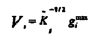
- the precoder value processor is configured to evaluate the following expression to determine the unit-norm linear precoding vector V i that maximizes the signal to interference noise ratio (SINR i ) for wireless terminal i:
- V i K ⁇ i - ⁇ / 2 ⁇ g i max
- g i max is a unit-norm, eigen vector associated with a maximum eigen value of a matrix K ⁇ i - 1 2 ⁇ K i ⁇ K ⁇ i - ⁇ 2
- K i is a covariance matrix
- K i E h ij ⁇ h ij ⁇ of each row of matrix channel H, for wireless terminal i .
- SINR target average signal to interference noise
- the technology concerns a method of coding signals for transmission from a wireless network to plural wireless terminals in radio frequency communication with the network (the network comprising plural transmitters).
- the method comprises using a processor to develop a set of precoder values for use in precoding signals transmitted from the plural transmitters. Each precoding value is associated with one wireless terminal.
- the set of precoder values is determined such that a set of target average signal to interference noise (SINR) ratios is achieved essentially simultaneously by the plural wireless terminals with a predetermined total transmit power.
- the method further comprises using the precoder values for coding the signals transmitted from the plural transmitters.
- SINR target average signal to interference noise
- Fig. 1 is a diagrammatic view of a wireless network comprising plural transmitters for communicating with plural wireless terminals.
- Fig. 2 is a flowchart showing example, non-limiting, basic acts or steps involved in an example embodiment of a precoder value determination procedure.
- processors may be provided through the use of dedicated hardware as well as hardware capable of executing software in association with appropriate software.
- the functions may be provided by a single dedicated processor, by a single shared processor, or by a plurality of individual processors, some of which may be shared or distributed.
- explicit use of the term "processor” or “controller” should not be construed to refer exclusively to hardware capable of executing software, and may include, without limitation, digital signal processor (DSP) hardware, read only memory (ROM) for storing software, random access memory (RAM), and non-volatile storage.
- DSP digital signal processor
- ROM read only memory
- RAM random access memory
- Fig. 1 illustrates an example wireless network 20 which participates in radio frequency communication over a radio or air interface 22 with plural wireless terminals 30, such as wireless terminals 30 l through 30 m .
- Each of the wireless terminals 30 is shown as having plural receivers, e.g., plural antennas 32.
- wireless terminal 30 1 has antennas 32 1.1 through 32 l,r ;
- wireless terminal 30 2 has antennas 32 2,1 through 32 2,r ; and so forth so that wireless terminal 30 i has plural antennas 32 i,1 through 32 i,r and wireless terminal 30 m has plural antennas 32 m,l through 32 m,r . While it so happens that the Fig. 1 illustration shows each of the wireless terminals 30 as having the same number (e.g., "r" number) of antennas, such need not be the case as different wireless terminals 30 can have differing numbers of antennas.
- the network comprises plural transmitters 40 (e.g., transmitters 40 1 through 40 1 ); precoder value processor 42; and, precoder 44.
- Each transmitter 40 comprises a transmitting antenna, and in such sense the terms "transmitter” and “antenna” are utilized interchangeably.
- Precoder value processor 42 is configured to develop a set of frequency-independent, linear precoder values.
- Precoder 44 is configured to use the precoder values developed by precoder value processor 42 for encoding the signals transmitted from the plural transmitters 40.
- the precoder value processor is configured to develop a set of (e.g., frequency-independent, linear) precoder values V (e.g., V 1 ...V t ) used to encode the signals transmitted from the plural transmitters.
- the set of precoder values V can take the form of a linear precoding matrix, where the t-th column of V is the vector V t ..
- Each precoding vector V i is associated with one wireless terminal 30 i .
- the set of precoder values V is determined such that a set of target average signal to interference noise (SINR) ratios is achieved (e.g., essentially simultaneously) by the plural wireless terminals with a predetermined total transmit power.
- SINR target average signal to interference noise
- the predetermined total transmit power is minimum total transmit power.
- the transmitters 40 of the wireless network 20 can be co-located at a same node of wireless network 20, or not co-located. By “not co-located” includes scenarios in which the transmitters 40 are situated at different nodes of wireless network 20 or situated at differing locations of the same node.
- a “node” can be, for example, the type of nodes that is referred to as a base station transceiver, a radio base station, or a NodeB (e.g., BNode).
- precoder value processor 42 receives inputs 46 as described herein.
- the set of precoder values V are applied to precoder 44.
- each precoder value V j is applied to a first input terminal of a respective multiplier 48 which comprises precoder 44.
- a second input terminal of each multiplier 48 receives a portion x j of an information stream x to be transmitted over the transmitters 40.
- multiplier 48 j receives precoder value V j and information stream portion x j , and yields the product x j V j .
- the products of all of the multipliers 48 are applied to adders 50, each adder 50 being associated with an associated transmitter 40 for feeding the associated transmitter 40 with the signal to be transmitted by the associated transmitter 40.
- precoder value processor 42 is configured to implement an iterative procedure that comprises, for each user i, (1) determining a unit-norm linear precoding vector V i that maximizes the signal to interference noise ratio (SINR i ) for wireless terminal i; and (2) determining a minimum sum power set that satisfies the set of target average signal to interference noise (SINR) ratios.
- precoder value processor 42 needs know statistics of the downlink channel for each wireless terminal 30, but need not know the instantaneous realization of the downlink channel (and thus eliminates the large amount of feedback and overhead which attended prior art precoding schemes).
- SINR target average signal to interference noise
- the network 20 sends independent messages to m number of receivers.
- Fig. 1 assumes by way of example that the network 20 has t number of transmit antennas 40, where not all these antennas are necessarily co-located.
- User i, i 1,2,.., m, has r number of receive antennas. It is assumed that there is an average total power constraint P at the network 20.
- y i is the output vector, received by user i. This vector is of size r x 1.
- H i is the matrix channel for user i whose size is r x t .
- n i is a Gaussian, circularly symmetric, complex-valued random noise vector with zero mean and normalized covariance I .
- Each row of the channel matrix H i is the channel to a different antenna of user i , and h ij ⁇ is used to denote the j -th row of H i .
- the transmitter i.e. the network
- the transmitter only knows the statistics of the H i , and we assume that different elements of the H i are complex, circularly symmetric, zero-mean, Gaussian random variables. We furthermore assume that different rows of each H i are independent and identically distributed, i.e. different receive antennas for each mobile i are independent and statistically identical.
- K i denotes the covariance matrix of each row of H i .
- K i E h ij ⁇ h ij ⁇ where h ij ⁇ is the j -th row of H i .
- K i in Eq. (3) does not depend on j .
- Expression (4) describes the signal that is received on the j -th antenna of the i-th user.
- the term in parenthesis in Expression (6) can be considered the desired signal at the output of the j -th antenna of user i , and w ij can be considered noise+interference at the j-th antenna of user i.
- the average input SINR at the j th antenna of user i is defined as the ratio of the average power of these two terms, as shown in Expression (7).
- SINR ij E h ij ⁇ ⁇ V i ⁇ x i 2 E w ij 2
- the expectation in Eq. (7) is over all realization of h ij . From Expression (7), and recalling that the different rows of H i are independent, identically distributed random vectors, it is apparent that SINR ij does not depend on j .
- SINR i is used to refer to the common average input SINR at any of the antennas of mobile i . In other words, the average input SINR is the same at all the receive antennas of each mobile.
- the diagonal matrix D d is defined as in Expression (15).
- D d diag b 1 , b 2 , ... , b m
- p i the average power of x i .
- SINR i p i ⁇ V i ⁇ ⁇ K i ⁇ V i 1 + ⁇ j ⁇ i V i ⁇ ⁇ L j ⁇ V i ⁇ p j
- K ⁇ i K ⁇ i 1 / 2 ⁇ K ⁇ i 1 / 2 ⁇ ) .
- Fig. 2 illustrates example, non-limiting, basic acts or steps involved in an example embodiment of a precoder value determination procedure performed by precoder value processor 42.
- precoder value processor 42 can be realized by a processor or controller as those terms are expansively explained herein.
- Act 2-1 of the precoder value determination procedure of Fig. 2 comprises reception or otherwise obtaining the inputs 46 useful for performing the precoder value determination procedure.
- inputs 46 useful for performing the precoder value determination procedure.
- precoder value processor 42 There are three basic types of inputs 46 which are obtained by precoder value processor 42:
- SINR i is the desired SINR value for the i -th user.
- SINR i is the desired SINR value for the i -th user.
- the desired SINR value for the i -th user is obtained based on the quality of service requirements of each user.
- each mobile i can measure its matrix K i and transmit this measured matrix to the network using the uplink channel.
- matrix K i is frequency independent and it changes at a much slower rate than the actual channel of the i-th mobile. Hence, transmitting this matrix from the mobile to the network will consume a small amount of resources on the uplink channel.
- a starting value for the vector p(0) [1 1 ... 1] T to be used in a first iteration of the iterative precoder value determination procedure.
- T transpose of a matrix/vector.
- Expression (48) which concerns the precoder vectors or weight vectors.
- g i n eig max K ⁇ i n ⁇ K i ⁇ K ⁇ ⁇ / 2 i n
- a n a 1 n ⁇ a 2 n .... a m n T
- Act 2-3 comprises performing/evaluating Expression (54) through Expression (58) as set forth below.
- An advantage of the coordination schemes disclosed herein is that they require a lot less feedback/overhead compared to the existing coherent coordination schemes.
Landscapes
- Engineering & Computer Science (AREA)
- Computer Networks & Wireless Communication (AREA)
- Signal Processing (AREA)
- Power Engineering (AREA)
- Mobile Radio Communication Systems (AREA)
- Radio Transmission System (AREA)
Claims (13)
- Knoten (20) eines drahtlosen Netzwerks, der an Funkfrequenzkommunikation mit mehreren drahtlosen Endgeräten beteiligt ist, wobei der Knoten (20) mehrere Sender (40) umfasst; wobei der Knoten (20) gekennzeichnet ist durch:einen Vorcodiererwertprozessor (42), der dafür konfiguriert ist, eine Menge von frequenzunabhängigen, linearen Vorcodiererwerten zu entwickeln, wobei jeder Vektor der Menge einem drahtlosen Endgerät zugeordnet ist, wobei die Menge von Vorcodiererwerten so bestimmt wird, dass eine Menge von angestrebten mittleren Verhältnissen von Signal und Störung plus Rauschen (SINR) bei einer vorbestimmten Gesamtsendeleistung im wesentlichen gleichzeitig durch die mehreren drahtlosen Endgeräte erreicht wird, wobei die mittleren Verhältnisse von Signal und Störung plus Rauschen (SINR) sich auf das gemeinsame mittlere Eingangs-SINR an irgendeiner der Antennen des drahtlosen Endgeräts beziehen, undeinen Vorcodierer (44), der dafür konfiguriert ist, die Vorcodiererwerte zum Codieren der von den mehreren Sendern (40) gesendeten Signale zu verwenden.
- Vorrichtung nach Anspruch 1, wobei die vorbestimmte Gesamtsendeleistung die minimale Gesamtsendeleistung ist.
- Vorrichtung nach Anspruch 1, wobei der Vorcodiererwertprozessor (42) dafür konfiguriert ist, eine iterative Prozedur zu implementieren, die umfasst:(1) Bestimmen eines linearen Einheits-Vorcodierungsvektors Vi , der das Verhältnis von Signal und Störung plus Rauschen (SINRi) für das drahtlose Endgerät i maximiert; und(2) Bestimmen einer minimalen Summenleistungsmenge, welche die Menge von angestrebten mittleren Verhältnissen von Signal und Störung plus Rauschen (SINR) erfüllt.
- Vorrichtung nach Anspruch 3, wobei der Vorcodiererwertprozessor (42) dafür konfiguriert ist, den folgenden Ausdruck zu bewerten, um den linearen Einheits-Vorcodierungsvektor Vi zu bestimmen, der das Verhältnis von Signal und Störung plus Rauschen (SINRi) für das drahtlose Endgerät i maximiert:
wobei


- Vorrichtung nach Anspruch 3, wobei der Vorcodiererwertprozessor (42) dafür konfiguriert ist, den folgenden Ausdruck zu bewerten, um die minimale Summenleistungsmenge pmin zu bestimmen, welche die Menge von angestrebten mittleren Verhältnissen von Signal und Störung plus Rauschen (SINR) erfüllt:

wobei Du eine Diagonalmatrix ist, die als Du = diag{a(1), a(2), ..., a(m)} definiert ist, wobei a ein Vektor ist, dessen i-tes Element

- Vorrichtung nach Anspruch 1, wobei der Vorcodiererwertprozessor (42) dafür konfiguriert ist, eine Menge von frequenzunabhängigen, linearen Vorcodiererwerten zu entwickeln, und wobei die Menge von Vorcodiererwerten so bestimmt wird, dass die Menge von angestrebten mittleren Verhältnissen von Signal und Störung plus Rauschen (SINR) im wesentlichen gleichzeitig durch die mehreren drahtlosen Endgeräte erreicht wird.
- Vorrichtung nach Anspruch 1, wobei der Vorcodiererwertprozessor (42) dafür konfiguriert ist, eine iterative Prozedur zum Bestimmen der Einheits-Vorcodierungsvektoren für jeden Teilnehmer zu implementieren.
- Verfahren zum Codieren von Signalen zum Senden von einem drahtlosen Netzwerk an mehrere drahtlose Endgeräte in Funkfrequenzkommunikation mit dem Netzwerk, wobei das Netzwerk mehrere Sender (40) umfasst; wobei das Verfahren gekennzeichnet ist durch:Verwenden eines Vorcodiererwertprozessor (42), um eine Menge von Vorcodiererwerten zu entwickeln, wobei jeder Vektor der Menge einem drahtlosen Endgerät zugeordnet ist, wobei die Menge von Vorcodiererwerten so bestimmt wird, dass eine Menge von angestrebten mittleren Verhältnissen von Signal und Störung plus Rauschen (SINR) bei einer vorbestimmten Gesamtsendeleistung im wesentlichen gleichzeitig durch die mehreren drahtlosen Endgeräte erreicht wird, wobei die mittleren Verhältnisse von Signal und Störung plus Rauschen (SINR) sich auf das gemeinsame mittlere Eingangs-SINR an irgendeiner der Antennen des drahtlosen Endgeräts beziehen, undVerwenden der Vorcodiererwerte zum Codieren der Signale, die von den mehreren Sendern (40) gesendet werden.
- Verfahren nach Anspruch 8, wobei die vorbestimmte Gesamtsendeleistung die minimale Gesamtsendeleistung ist.
- Verfahren nach Anspruch 8, ferner umfassend: Bestimmen der Vorcodiererwerte unter Verwendung einer iterativen Prozedur, die umfasst:(1) Bestimmen eines linearen Einheits-Vorcodierungsvektors Vi , der das Verhältnis von Signal und Störung plus Rauschen (SINRi) für das drahtlose Endgerät i maximiert; und(2) Bestimmen einer minimalen Summenleistungsmenge, welche die Menge von angestrebten mittleren Verhältnissen von Signal und Störung plus Rauschen (SINR) erfüllt.
- Verfahren nach Anspruch 10, ferner umfassend: Bewerten des folgenden Ausdrucks, um den linearen Einheits-Vorcodierungsvektor Vi zu bestimmen, der das Verhältnis von Signal und Störung plus Rauschen (SINRi) für das drahtlose Endgerät i maximiert:

wobei


- Verfahren nach Anspruch 10, ferner umfassend: Bewerten des folgenden Ausdrucks, um die minimale Summenleistungsmenge pmin zu bestimmen, welche die Menge von angestrebten mittleren Verhältnissen von Signal und Störung plus Rauschen (SINR) erfüllt:

wobei Du eine Diagonalmatrix ist, die als Du = diag {a(1), a(2), ..., a(m)} definiert ist, wobei a ein Vektor ist, dessen i-tes Element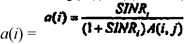
ist, und A eine m × m-Matrix ist, deren (i,j)-ter Eintrag
- Verfahren nach Anspruch 8, ferner umfassend: Entwickeln einer Menge von frequenzunabhängigen, linearen Vorcodiererwerten, wodurch die Menge von angestrebten mittleren Verhältnissen von Signal und Störung plus Rauschen (SINR) im wesentlichen gleichzeitig durch die mehreren drahtlosen Endgeräte erreicht wird.
Applications Claiming Priority (2)
| Application Number | Priority Date | Filing Date | Title |
|---|---|---|---|
| US12/027,421 US8064849B2 (en) | 2008-02-07 | 2008-02-07 | Precoding for multiple anntennas |
| PCT/EP2008/059165 WO2009097911A1 (en) | 2008-02-07 | 2008-07-14 | Precoding for multiple antennas |
Publications (2)
| Publication Number | Publication Date |
|---|---|
| EP2248276A1 EP2248276A1 (de) | 2010-11-10 |
| EP2248276B1 true EP2248276B1 (de) | 2012-02-15 |
Family
ID=39874193
Family Applications (1)
| Application Number | Title | Priority Date | Filing Date |
|---|---|---|---|
| EP08786122A Active EP2248276B1 (de) | 2008-02-07 | 2008-07-14 | Vorkodierung für mehrfachantennen |
Country Status (4)
| Country | Link |
|---|---|
| US (1) | US8064849B2 (de) |
| EP (1) | EP2248276B1 (de) |
| AT (1) | ATE545989T1 (de) |
| WO (1) | WO2009097911A1 (de) |
Families Citing this family (12)
| Publication number | Priority date | Publication date | Assignee | Title |
|---|---|---|---|---|
| US8233559B2 (en) * | 2008-03-12 | 2012-07-31 | Lg Electronics Inc. | Method and apparatus for transmitting a pilot in multi-antenna system |
| JP5319770B2 (ja) * | 2008-07-14 | 2013-10-16 | テレフオンアクチーボラゲット エル エム エリクソン(パブル) | マルチユーザmimo通信システムのための干渉抑圧合成 |
| US8107550B2 (en) * | 2008-09-23 | 2012-01-31 | Alcatel Lucent | Methods for precoding signals for transmission in wireless MIMO system |
| KR101055573B1 (ko) * | 2009-03-16 | 2011-08-08 | 주식회사 팬택 | 다중 사용자, 다중 안테나 무선 송출 시스템에서의 프리 코딩 장치 |
| ES2557894T3 (es) * | 2009-04-14 | 2016-01-29 | Fraunhofer-Gesellschaft zur Förderung der angewandten Forschung e.V. | Método y dispositivo para procesamiento de datos en una red de comunicación |
| US8233517B2 (en) * | 2009-07-28 | 2012-07-31 | Telefonaktiebolaget L M Ericsson (Publ) | Pilot-based SINR estimation for MIMO systems |
| US20130016616A1 (en) | 2010-03-25 | 2013-01-17 | Telefonaktiebolaget L M Ericsson (Publ) | Method for backhaul link protection in a mimo wireless link |
| GB2483306A (en) * | 2010-09-06 | 2012-03-07 | Fujitsu Ltd | Base station cooperation in a MIMO wireless communication system using inter-group interference information to improve system performance |
| US8660202B2 (en) * | 2010-09-16 | 2014-02-25 | Nec Laboratories America, Inc. | Robust precoder and receiver filter design for Gaussian interference channel |
| US20150178825A1 (en) * | 2013-12-23 | 2015-06-25 | Citibank, N.A. | Methods and Apparatus for Quantitative Assessment of Behavior in Financial Entities and Transactions |
| CN111667381B (zh) * | 2020-06-17 | 2023-02-24 | 南方电网科学研究院有限责任公司 | 一种输电线路走廊通信覆盖与数据传输方法 |
| CN118018075B (zh) * | 2024-04-08 | 2024-08-09 | 荣耀终端有限公司 | 通信方法、通信装置、计算机可读存储介质及相关系统 |
Family Cites Families (10)
| Publication number | Priority date | Publication date | Assignee | Title |
|---|---|---|---|---|
| US6360079B2 (en) * | 1997-02-12 | 2002-03-19 | Interdigital Technology Corporation | Global channel power control to minimize spillover in a wireless communication environment |
| CA2587770A1 (en) * | 2004-11-05 | 2006-05-18 | University Of Florida Research Foundation, Inc. | Uniform channel decomposition for mimo communications |
| US7515878B2 (en) * | 2005-09-21 | 2009-04-07 | Broadcom Corporation | Method and system for greedy user group selection with range reduction for FDD multiuser MIMO downlink transmission with finite-rate channel state information feedback |
| KR101231357B1 (ko) * | 2006-04-06 | 2013-02-07 | 엘지전자 주식회사 | 다중 안테나 시스템에서 채널 상태 정보 귀환 방법 및데이터 송신 방법 |
| FI20065278A0 (fi) * | 2006-04-28 | 2006-04-28 | Nokia Corp | Prekoodausmenetelmä tiedonsiirrolle mimo radiojärjestelmässä |
| US20150030058A9 (en) * | 2006-05-17 | 2015-01-29 | Texas Instruments Inc. | Cqi feedback for mimo deployments |
| US9130618B2 (en) * | 2006-10-26 | 2015-09-08 | Alcatel Lucent | MIMO communication system with variable slot structure |
| US8849353B2 (en) * | 2007-04-27 | 2014-09-30 | Alcatel Lucent | Method of grouping users to reduce interference in MIMO-based wireless network |
| US20080316935A1 (en) * | 2007-06-19 | 2008-12-25 | Interdigital Technology Corporation | Generating a node-b codebook |
| US20090147728A1 (en) * | 2007-12-05 | 2009-06-11 | Atia George K | Wireless Cooperative Relay Network Transmitting Data using Imperfect CSI |
-
2008
- 2008-02-07 US US12/027,421 patent/US8064849B2/en active Active
- 2008-07-14 AT AT08786122T patent/ATE545989T1/de active
- 2008-07-14 WO PCT/EP2008/059165 patent/WO2009097911A1/en not_active Ceased
- 2008-07-14 EP EP08786122A patent/EP2248276B1/de active Active
Also Published As
| Publication number | Publication date |
|---|---|
| ATE545989T1 (de) | 2012-03-15 |
| EP2248276A1 (de) | 2010-11-10 |
| US20100081399A1 (en) | 2010-04-01 |
| US8064849B2 (en) | 2011-11-22 |
| WO2009097911A1 (en) | 2009-08-13 |
Similar Documents
| Publication | Publication Date | Title |
|---|---|---|
| EP2248276B1 (de) | Vorkodierung für mehrfachantennen | |
| EP3123627B1 (de) | Verfahren und vorrichtung zur planung in einem system mit mehreren eingängen und mehreren ausgängen | |
| US8467468B2 (en) | Transmitting and receiving apparatus having plural antenna in multi-user environments and method thereof | |
| US20230412430A1 (en) | Inforamtion reporting method and apparatus, first device, and second device | |
| EP3185434B1 (de) | Verfahren und vorrichtung zur strahlformung | |
| CN101867462A (zh) | 一种基于最小总误码率的多基站协作线性预编码方法 | |
| Abdelfatah et al. | A Study on the Basics Processes of Massive MIMO. | |
| Ghosh et al. | Outage-efficient strategies for multiuser MIMO networks with channel distribution information | |
| De Francisco et al. | Orthogonal linear beamforming in MIMO broadcast channels | |
| Jose et al. | Scheduling and pre-conditioning in multi-user MIMO TDD systems | |
| Zanella et al. | Reduced complexity power allocation strategies for MIMO systems with singular value decomposition | |
| Zhu et al. | Tunable SRS-aware robust coordinated beamforming design with channel aging | |
| Kountouris et al. | Transmission capacity scaling of SDMA in wireless ad hoc networks | |
| CN103607260B (zh) | 基于mimo系统总干扰泄漏最小的预编码矩阵组的选择算法 | |
| Heath et al. | Multiuser MIMO in distributed antenna systems | |
| Musavian et al. | On the achievable sum-rate of correlated MIMO multiple access channel with imperfect channel estimation | |
| Wu et al. | Enhanced time-shifted pilot based channel estimation in massive MIMO systems with finite number of antennas | |
| KR101806311B1 (ko) | 규준화된 빔포밍을 사용하는 네트워크 다중 입출력 통신 시스템 | |
| Tang et al. | Downlink path-based precoding in FDD massive MIMO systems without CSI feedback | |
| Kim et al. | Precoding design for minimizing age of information in downlink MU-MISO systems | |
| Davis et al. | Multi-antenna downlink broadcast using compressed-sensed medium access | |
| CN102404806B (zh) | 一种多输入多输出自适应模式切换方法和装置 | |
| Zhao et al. | Pilot contamination reduction in massive MIMO system | |
| Wang | MIMO system with receive combiner bank and power control for cognitive radio networks | |
| Ciflikli et al. | Evaluation of eigenvalue and block diagonalization beamforming precoding performance for 5G technology over rician channel |
Legal Events
| Date | Code | Title | Description |
|---|---|---|---|
| PUAI | Public reference made under article 153(3) epc to a published international application that has entered the european phase |
Free format text: ORIGINAL CODE: 0009012 |
|
| 17P | Request for examination filed |
Effective date: 20100810 |
|
| AK | Designated contracting states |
Kind code of ref document: A1 Designated state(s): AT BE BG CH CY CZ DE DK EE ES FI FR GB GR HR HU IE IS IT LI LT LU LV MC MT NL NO PL PT RO SE SI SK TR |
|
| AX | Request for extension of the european patent |
Extension state: AL BA MK RS |
|
| DAX | Request for extension of the european patent (deleted) | ||
| GRAP | Despatch of communication of intention to grant a patent |
Free format text: ORIGINAL CODE: EPIDOSNIGR1 |
|
| GRAS | Grant fee paid |
Free format text: ORIGINAL CODE: EPIDOSNIGR3 |
|
| GRAA | (expected) grant |
Free format text: ORIGINAL CODE: 0009210 |
|
| AK | Designated contracting states |
Kind code of ref document: B1 Designated state(s): AT BE BG CH CY CZ DE DK EE ES FI FR GB GR HR HU IE IS IT LI LT LU LV MC MT NL NO PL PT RO SE SI SK TR |
|
| REG | Reference to a national code |
Ref country code: CH Ref legal event code: EP Ref country code: GB Ref legal event code: FG4D |
|
| REG | Reference to a national code |
Ref country code: IE Ref legal event code: FG4D |
|
| REG | Reference to a national code |
Ref country code: AT Ref legal event code: REF Ref document number: 545989 Country of ref document: AT Kind code of ref document: T Effective date: 20120315 |
|
| REG | Reference to a national code |
Ref country code: DE Ref legal event code: R096 Ref document number: 602008013468 Country of ref document: DE Effective date: 20120412 |
|
| REG | Reference to a national code |
Ref country code: NL Ref legal event code: VDEP Effective date: 20120215 |
|
| LTIE | Lt: invalidation of european patent or patent extension |
Effective date: 20120215 |
|
| PG25 | Lapsed in a contracting state [announced via postgrant information from national office to epo] |
Ref country code: IS Free format text: LAPSE BECAUSE OF FAILURE TO SUBMIT A TRANSLATION OF THE DESCRIPTION OR TO PAY THE FEE WITHIN THE PRESCRIBED TIME-LIMIT Effective date: 20120615 Ref country code: NO Free format text: LAPSE BECAUSE OF FAILURE TO SUBMIT A TRANSLATION OF THE DESCRIPTION OR TO PAY THE FEE WITHIN THE PRESCRIBED TIME-LIMIT Effective date: 20120515 Ref country code: NL Free format text: LAPSE BECAUSE OF FAILURE TO SUBMIT A TRANSLATION OF THE DESCRIPTION OR TO PAY THE FEE WITHIN THE PRESCRIBED TIME-LIMIT Effective date: 20120215 Ref country code: LT Free format text: LAPSE BECAUSE OF FAILURE TO SUBMIT A TRANSLATION OF THE DESCRIPTION OR TO PAY THE FEE WITHIN THE PRESCRIBED TIME-LIMIT Effective date: 20120215 Ref country code: HR Free format text: LAPSE BECAUSE OF FAILURE TO SUBMIT A TRANSLATION OF THE DESCRIPTION OR TO PAY THE FEE WITHIN THE PRESCRIBED TIME-LIMIT Effective date: 20120215 |
|
| PG25 | Lapsed in a contracting state [announced via postgrant information from national office to epo] |
Ref country code: FI Free format text: LAPSE BECAUSE OF FAILURE TO SUBMIT A TRANSLATION OF THE DESCRIPTION OR TO PAY THE FEE WITHIN THE PRESCRIBED TIME-LIMIT Effective date: 20120215 Ref country code: PT Free format text: LAPSE BECAUSE OF FAILURE TO SUBMIT A TRANSLATION OF THE DESCRIPTION OR TO PAY THE FEE WITHIN THE PRESCRIBED TIME-LIMIT Effective date: 20120615 Ref country code: BE Free format text: LAPSE BECAUSE OF FAILURE TO SUBMIT A TRANSLATION OF THE DESCRIPTION OR TO PAY THE FEE WITHIN THE PRESCRIBED TIME-LIMIT Effective date: 20120215 Ref country code: LV Free format text: LAPSE BECAUSE OF FAILURE TO SUBMIT A TRANSLATION OF THE DESCRIPTION OR TO PAY THE FEE WITHIN THE PRESCRIBED TIME-LIMIT Effective date: 20120215 Ref country code: GR Free format text: LAPSE BECAUSE OF FAILURE TO SUBMIT A TRANSLATION OF THE DESCRIPTION OR TO PAY THE FEE WITHIN THE PRESCRIBED TIME-LIMIT Effective date: 20120516 Ref country code: PL Free format text: LAPSE BECAUSE OF FAILURE TO SUBMIT A TRANSLATION OF THE DESCRIPTION OR TO PAY THE FEE WITHIN THE PRESCRIBED TIME-LIMIT Effective date: 20120215 |
|
| REG | Reference to a national code |
Ref country code: AT Ref legal event code: MK05 Ref document number: 545989 Country of ref document: AT Kind code of ref document: T Effective date: 20120215 |
|
| PG25 | Lapsed in a contracting state [announced via postgrant information from national office to epo] |
Ref country code: CY Free format text: LAPSE BECAUSE OF FAILURE TO SUBMIT A TRANSLATION OF THE DESCRIPTION OR TO PAY THE FEE WITHIN THE PRESCRIBED TIME-LIMIT Effective date: 20120215 |
|
| PG25 | Lapsed in a contracting state [announced via postgrant information from national office to epo] |
Ref country code: CZ Free format text: LAPSE BECAUSE OF FAILURE TO SUBMIT A TRANSLATION OF THE DESCRIPTION OR TO PAY THE FEE WITHIN THE PRESCRIBED TIME-LIMIT Effective date: 20120215 Ref country code: DK Free format text: LAPSE BECAUSE OF FAILURE TO SUBMIT A TRANSLATION OF THE DESCRIPTION OR TO PAY THE FEE WITHIN THE PRESCRIBED TIME-LIMIT Effective date: 20120215 Ref country code: RO Free format text: LAPSE BECAUSE OF FAILURE TO SUBMIT A TRANSLATION OF THE DESCRIPTION OR TO PAY THE FEE WITHIN THE PRESCRIBED TIME-LIMIT Effective date: 20120215 Ref country code: EE Free format text: LAPSE BECAUSE OF FAILURE TO SUBMIT A TRANSLATION OF THE DESCRIPTION OR TO PAY THE FEE WITHIN THE PRESCRIBED TIME-LIMIT Effective date: 20120215 Ref country code: SI Free format text: LAPSE BECAUSE OF FAILURE TO SUBMIT A TRANSLATION OF THE DESCRIPTION OR TO PAY THE FEE WITHIN THE PRESCRIBED TIME-LIMIT Effective date: 20120215 Ref country code: SE Free format text: LAPSE BECAUSE OF FAILURE TO SUBMIT A TRANSLATION OF THE DESCRIPTION OR TO PAY THE FEE WITHIN THE PRESCRIBED TIME-LIMIT Effective date: 20120215 |
|
| PG25 | Lapsed in a contracting state [announced via postgrant information from national office to epo] |
Ref country code: SK Free format text: LAPSE BECAUSE OF FAILURE TO SUBMIT A TRANSLATION OF THE DESCRIPTION OR TO PAY THE FEE WITHIN THE PRESCRIBED TIME-LIMIT Effective date: 20120215 Ref country code: IT Free format text: LAPSE BECAUSE OF FAILURE TO SUBMIT A TRANSLATION OF THE DESCRIPTION OR TO PAY THE FEE WITHIN THE PRESCRIBED TIME-LIMIT Effective date: 20120215 |
|
| PLBE | No opposition filed within time limit |
Free format text: ORIGINAL CODE: 0009261 |
|
| STAA | Information on the status of an ep patent application or granted ep patent |
Free format text: STATUS: NO OPPOSITION FILED WITHIN TIME LIMIT |
|
| 26N | No opposition filed |
Effective date: 20121116 |
|
| PG25 | Lapsed in a contracting state [announced via postgrant information from national office to epo] |
Ref country code: AT Free format text: LAPSE BECAUSE OF FAILURE TO SUBMIT A TRANSLATION OF THE DESCRIPTION OR TO PAY THE FEE WITHIN THE PRESCRIBED TIME-LIMIT Effective date: 20120215 |
|
| PG25 | Lapsed in a contracting state [announced via postgrant information from national office to epo] |
Ref country code: MC Free format text: LAPSE BECAUSE OF NON-PAYMENT OF DUE FEES Effective date: 20120731 |
|
| REG | Reference to a national code |
Ref country code: CH Ref legal event code: PL |
|
| REG | Reference to a national code |
Ref country code: DE Ref legal event code: R097 Ref document number: 602008013468 Country of ref document: DE Effective date: 20121116 |
|
| REG | Reference to a national code |
Ref country code: FR Ref legal event code: ST Effective date: 20130329 |
|
| PG25 | Lapsed in a contracting state [announced via postgrant information from national office to epo] |
Ref country code: ES Free format text: LAPSE BECAUSE OF FAILURE TO SUBMIT A TRANSLATION OF THE DESCRIPTION OR TO PAY THE FEE WITHIN THE PRESCRIBED TIME-LIMIT Effective date: 20120526 Ref country code: LI Free format text: LAPSE BECAUSE OF NON-PAYMENT OF DUE FEES Effective date: 20120731 Ref country code: FR Free format text: LAPSE BECAUSE OF NON-PAYMENT OF DUE FEES Effective date: 20120731 Ref country code: CH Free format text: LAPSE BECAUSE OF NON-PAYMENT OF DUE FEES Effective date: 20120731 |
|
| REG | Reference to a national code |
Ref country code: IE Ref legal event code: MM4A |
|
| PG25 | Lapsed in a contracting state [announced via postgrant information from national office to epo] |
Ref country code: IE Free format text: LAPSE BECAUSE OF NON-PAYMENT OF DUE FEES Effective date: 20120714 Ref country code: BG Free format text: LAPSE BECAUSE OF FAILURE TO SUBMIT A TRANSLATION OF THE DESCRIPTION OR TO PAY THE FEE WITHIN THE PRESCRIBED TIME-LIMIT Effective date: 20120515 Ref country code: MT Free format text: LAPSE BECAUSE OF FAILURE TO SUBMIT A TRANSLATION OF THE DESCRIPTION OR TO PAY THE FEE WITHIN THE PRESCRIBED TIME-LIMIT Effective date: 20120215 |
|
| PG25 | Lapsed in a contracting state [announced via postgrant information from national office to epo] |
Ref country code: TR Free format text: LAPSE BECAUSE OF FAILURE TO SUBMIT A TRANSLATION OF THE DESCRIPTION OR TO PAY THE FEE WITHIN THE PRESCRIBED TIME-LIMIT Effective date: 20120215 |
|
| PG25 | Lapsed in a contracting state [announced via postgrant information from national office to epo] |
Ref country code: LU Free format text: LAPSE BECAUSE OF NON-PAYMENT OF DUE FEES Effective date: 20120714 |
|
| PG25 | Lapsed in a contracting state [announced via postgrant information from national office to epo] |
Ref country code: HU Free format text: LAPSE BECAUSE OF FAILURE TO SUBMIT A TRANSLATION OF THE DESCRIPTION OR TO PAY THE FEE WITHIN THE PRESCRIBED TIME-LIMIT Effective date: 20080714 |
|
| PGFP | Annual fee paid to national office [announced via postgrant information from national office to epo] |
Ref country code: GB Payment date: 20160727 Year of fee payment: 9 |
|
| GBPC | Gb: european patent ceased through non-payment of renewal fee |
Effective date: 20170714 |
|
| PG25 | Lapsed in a contracting state [announced via postgrant information from national office to epo] |
Ref country code: GB Free format text: LAPSE BECAUSE OF NON-PAYMENT OF DUE FEES Effective date: 20170714 |
|
| PGFP | Annual fee paid to national office [announced via postgrant information from national office to epo] |
Ref country code: DE Payment date: 20250729 Year of fee payment: 18 |