EP2248261B1 - Verfahren zum betrieb eines empfangsschemas mehrerer streams - Google Patents
Verfahren zum betrieb eines empfangsschemas mehrerer streams Download PDFInfo
- Publication number
- EP2248261B1 EP2248261B1 EP09708738A EP09708738A EP2248261B1 EP 2248261 B1 EP2248261 B1 EP 2248261B1 EP 09708738 A EP09708738 A EP 09708738A EP 09708738 A EP09708738 A EP 09708738A EP 2248261 B1 EP2248261 B1 EP 2248261B1
- Authority
- EP
- European Patent Office
- Prior art keywords
- frequency
- vco
- stream
- streams
- offset
- Prior art date
- Legal status (The legal status is an assumption and is not a legal conclusion. Google has not performed a legal analysis and makes no representation as to the accuracy of the status listed.)
- Active
Links
Images


Classifications
-
- H—ELECTRICITY
- H04—ELECTRIC COMMUNICATION TECHNIQUE
- H04N—PICTORIAL COMMUNICATION, e.g. TELEVISION
- H04N5/00—Details of television systems
- H04N5/44—Receiver circuitry for the reception of television signals according to analogue transmission standards
- H04N5/455—Demodulation-circuits
-
- H—ELECTRICITY
- H03—ELECTRONIC CIRCUITRY
- H03L—AUTOMATIC CONTROL, STARTING, SYNCHRONISATION OR STABILISATION OF GENERATORS OF ELECTRONIC OSCILLATIONS OR PULSES
- H03L7/00—Automatic control of frequency or phase; Synchronisation
- H03L7/06—Automatic control of frequency or phase; Synchronisation using a reference signal applied to a frequency- or phase-locked loop
- H03L7/16—Indirect frequency synthesis, i.e. generating a desired one of a number of predetermined frequencies using a frequency- or phase-locked loop
- H03L7/18—Indirect frequency synthesis, i.e. generating a desired one of a number of predetermined frequencies using a frequency- or phase-locked loop using a frequency divider or counter in the loop
- H03L7/197—Indirect frequency synthesis, i.e. generating a desired one of a number of predetermined frequencies using a frequency- or phase-locked loop using a frequency divider or counter in the loop a time difference being used for locking the loop, the counter counting between numbers which are variable in time or the frequency divider dividing by a factor variable in time, e.g. for obtaining fractional frequency division
- H03L7/1974—Indirect frequency synthesis, i.e. generating a desired one of a number of predetermined frequencies using a frequency- or phase-locked loop using a frequency divider or counter in the loop a time difference being used for locking the loop, the counter counting between numbers which are variable in time or the frequency divider dividing by a factor variable in time, e.g. for obtaining fractional frequency division for fractional frequency division
- H03L7/1976—Indirect frequency synthesis, i.e. generating a desired one of a number of predetermined frequencies using a frequency- or phase-locked loop using a frequency divider or counter in the loop a time difference being used for locking the loop, the counter counting between numbers which are variable in time or the frequency divider dividing by a factor variable in time, e.g. for obtaining fractional frequency division for fractional frequency division using a phase accumulator for controlling the counter or frequency divider
-
- H—ELECTRICITY
- H03—ELECTRONIC CIRCUITRY
- H03L—AUTOMATIC CONTROL, STARTING, SYNCHRONISATION OR STABILISATION OF GENERATORS OF ELECTRONIC OSCILLATIONS OR PULSES
- H03L7/00—Automatic control of frequency or phase; Synchronisation
- H03L7/06—Automatic control of frequency or phase; Synchronisation using a reference signal applied to a frequency- or phase-locked loop
- H03L7/16—Indirect frequency synthesis, i.e. generating a desired one of a number of predetermined frequencies using a frequency- or phase-locked loop
- H03L7/22—Indirect frequency synthesis, i.e. generating a desired one of a number of predetermined frequencies using a frequency- or phase-locked loop using more than one loop
- H03L7/23—Indirect frequency synthesis, i.e. generating a desired one of a number of predetermined frequencies using a frequency- or phase-locked loop using more than one loop with pulse counters or frequency dividers
-
- H—ELECTRICITY
- H04—ELECTRIC COMMUNICATION TECHNIQUE
- H04N—PICTORIAL COMMUNICATION, e.g. TELEVISION
- H04N21/00—Selective content distribution, e.g. interactive television or video on demand [VOD]
- H04N21/60—Network structure or processes for video distribution between server and client or between remote clients; Control signalling between clients, server and network components; Transmission of management data between server and client, e.g. sending from server to client commands for recording incoming content stream; Communication details between server and client
- H04N21/61—Network physical structure; Signal processing
- H04N21/6106—Network physical structure; Signal processing specially adapted to the downstream path of the transmission network
- H04N21/6118—Network physical structure; Signal processing specially adapted to the downstream path of the transmission network involving cable transmission, e.g. using a cable modem
-
- H—ELECTRICITY
- H04—ELECTRIC COMMUNICATION TECHNIQUE
- H04N—PICTORIAL COMMUNICATION, e.g. TELEVISION
- H04N21/00—Selective content distribution, e.g. interactive television or video on demand [VOD]
- H04N21/40—Client devices specifically adapted for the reception of or interaction with content, e.g. set-top-box [STB]; Operations thereof
- H04N21/41—Structure of client; Structure of client peripherals
- H04N21/426—Internal components of the client ; Characteristics thereof
- H04N21/42607—Internal components of the client ; Characteristics thereof for processing the incoming bitstream
- H04N21/4263—Internal components of the client ; Characteristics thereof for processing the incoming bitstream involving specific tuning arrangements, e.g. two tuners
-
- H—ELECTRICITY
- H04—ELECTRIC COMMUNICATION TECHNIQUE
- H04N—PICTORIAL COMMUNICATION, e.g. TELEVISION
- H04N21/00—Selective content distribution, e.g. interactive television or video on demand [VOD]
- H04N21/40—Client devices specifically adapted for the reception of or interaction with content, e.g. set-top-box [STB]; Operations thereof
- H04N21/41—Structure of client; Structure of client peripherals
- H04N21/426—Internal components of the client ; Characteristics thereof
- H04N21/42676—Internal components of the client ; Characteristics thereof for modulating an analogue carrier signal to encode digital information or demodulating it to decode digital information, e.g. ADSL or cable modem
Definitions
- the present invention relates to a method of operating a multi-stream reception scheme.
- the present invention has particular, but not exclusive application in apparatus for use in Data Over Cable Service Interface Specifications (DOCSIS) applications.
- DOCSIS Data Over Cable Service Interface Specifications
- the TV channel bandwidths will be referred to the North-America NTSC standard of 6 MHz but the present invention can be adapted to conform to other bandwidth standards such as the European cable PAL TV standard which specifies 8MHz channel bandwidth.
- JP2006173922A describes a broadcast signal receiving device provided with a plurality of tuners.
- a local oscillation frequency of a PLL circuit is shifted so that local deterioration in projecting equivafent C/N ratio is not caused even in case of mutual interference.
- a local oscillation frequency amplified by the PLL circuit is shifted by shifting the fundamental frequency of a crystal oscillator.
- CN 1992839A describes a broadcast receiver and relative tuner control method, wherein it comprises main and sub tuners, main and sub demodulators, and the second memory for storing the phase-lock loop data which can control the vibration frequency; the interference control part for selecting non-interference program frequency from present programs to reach phase-lock loop data to be stored in sub tuner, when the sub tuner is closed. And method comprises that: judging if the sub-main picture is closed, if it is closed, recording the phase-lock loop data selected by main tuner, recording non-interference phase-lock loop data into the sub tuner; via recorded phase-lock loop data, selecting programs in main and sub tuners.
- a typical application is a "watch and record" feature for Set-Top-Boxes (STB) and PG-TV cards.
- a relatively new application is the use of so-called bonded channels for increasing data rates in cable modem applications. In bonded channels the data streams of multiple channels are combined to a single high data rate stream.
- the DOCSIS3.0 AND DOCSIS4.0 standards are dedicated for these kinds of applications.
- Embodiments of the invention can avoid frequency pulling in multi-stream receivers.
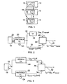
- the illustrated multiband TV receiver shown in Figure 1 comprises receiver streams 10, 12, 14, each receiver stream having its own inductance-capacitance voltage controlled oscillator (LC-VCO) 16.
- the double headed arrows illustrate the interaction between the LC-VCOs which lead to oscillator pulling causing degradation in the frequencies generated.
- a way of reducing, if not eliminating, the oscillator pulling is to maximize the frequency distance between the LC-VCOs 16 thereby avoiding the interaction.
- a method of increasing the frequency distance is to produce a frequency offset between each of the oscillators in the respective receiver streams 10, 12 and 14.
- FIG. 2 illustrates a first architecture for providing an offset frequency.
- a fractional-N phase locked loop (PLL) 20 has an input 22 for a reference frequency f ref derived from a stable frequency source 18, such as a crystal oscillator, and another input 24 for a channel selection indication in the form of a digital word.
- the output from the PLL 20 is divided into two paths 30, 32.
- the path 30 is coupled to an input 34 of a single sideband (SSB) mixer 36 which functions as a frequency adder.
- SSB single sideband
- An output from the frequency divider 38 is coupled to an input 40 of the SSB mixer 36.
- An output 42 of the SSB mixer 36 comprises f out which consists of f offset ⁇ f channel .
- the input 40 of the SSB mixer 36 may be an inverting or non-inverting input depending on whether the offset frequency is to be subtracted or added to the channel frequency.
- Figure 3 illustrates a second architecture in which the offset frequency is derived using a separate integer-N PLL 44.
- the reference frequency f ref is supplied simultaneously to the fractional-N PLL 20 which provides the channel frequency f channel and to the integer-N PLL 44 which provides the offset frequency f offset .
- LO local oscillator
- stream #1 and #2 are 6MHz bandwidth US cable streams and the stream #1 is in a "watch” mode and the stream #2 is in a "record” mode.
- the frequency plan for stream #1 could be :
- the on-demand offset frequency generation architectures and algorithms monitor the LO frequency change in a specific stream and intelligently set the frequency planning of the specific stream to maximize the distance with VCOs of other streams. This is done by adjusting on demand the offset frequency generation and the SSB mixer 36 mode.
- a first embodiment of the invention provides some on-demand frequency offset generation for a dual stream reception that minimizes the number of LC-VCOs to two VCOs having identical architectures while minimizing the tuning range of the VCOs. Combined to this architecture there will be described a frequency plan algorithm that maximizes the distance between the VCOs of stream #1 and the stream #2.
- a second embodiment of the invention overcomes a N-stream application (with N>2) by making use of an offset PLL and a channel PLL for each stream.
- Each stream uses identical offset and channel PLLs.
- the frequency planning of each stream is selected on-demand to maximize the distance between the VCOs.
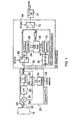
- the main components are the fractional-N PLL which has an input coupled to a source 18 of reference frequency f ref , such as a crystal oscillator, and an output coupled to an on-demand offset frequency generator (OFG) 64.
- a source 18 of reference frequency f ref such as a crystal oscillator
- OFG on-demand offset frequency generator
- An output of the on-demand OFG 64 coupled to a divider 74 which provides the local oscillator frequencies to mixers (not shown).
- the architecture of the fractional-N PLL is typical and comprises a LC-VCO 50 which generates the channel frequency f channel which is supplied to the on-demand OFG 64 and to a divider 52.
- a channel selection input 24 is coupled to a ⁇ modulator 54 which generates the divider ratio (N + K) used to divide the channel frequency f channel .
- the symbol "%" is used to indicate the operation of dividing.
- An output from the divider 52 is supplied to a mixer 58 which also receives the reference frequency f ref .
- the difference between the two frequencies is integrated in a low pass filter 62 to provide a slowly changing control voltage for the LC-VCO 50.
- the channel frequency f channel is applied to the signal paths 30, 32.
- the path 30 includes a two pole changeover switch 66 having one pole coupled to a quadrature generation stage 68 which in operation produces quadrature related (I ,Q) versions of the channel frequency f channel .
- the I and Q versions of the channel frequency are applied to an input 34 of a SSB mixer 36.
- the path 38 includes a divider 38 which divides the channel frequency using a divider ratio selected from a multiple divider ratio, for example P/(P + 1)/ (P +2), to produce the desired offset frequency f offset and a another quadrature generation stage 70 for producing quadrature related (I, Q) versions of the offset frequency.
- the I and Q versions of the offset frequency are applied to an input 40 of the SSB mixer 36.
- An output of the SSB mixer 36 comprises f channel ⁇ f offset depending on whether the SSB mixer mode selected on-demand to be additive or subtractive. This frequency is supplied to one pole of a two pole changeover switch 72. An output of the switch 72 is coupled to the divider 74.
- a second pole of the switch 66 is connected to a second pole of the switch 72.
- the switches 66 and 72 can be operated in a first condition in which the first poles are selected and the output signal from the on-demand OFG is f channel ⁇ f offset and in a second condition in which the second poles are selected and the output frequency is f channel .
- a receiver there may be two on-demand frequency generators of the type shown in Figure 4 having LC-VCOs with the same architectures and the same divider ratios R in the local oscillator dividers 74, the reference frequency f ref being obtained from a single reference source 18.
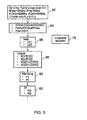
- Figure 5 is a flow chart of a control algorithm to maximize the on-demand frequency distance between 2 VCOs while minimizing the VCO tuning range.
- the flow chart comprises three sections, namely, sequence 76 initialization, sequence 78 to define OFG parameters and sequence 80 Enable/Disable OFG for stream # 1 or # 2.
- Block 86 relates to setting-up LO (1) and LO (2).
- VCO OFG VCO y . 1 + Sign / X
- the flow chart now proceeds to the sequence 80.
- the use of the multiple divider ratio 4/5/6 enables to reduce the VCO tuning range from 66.4% to 49.7%, to maintain the offset frequency value > 1005 MHz to avoid leakage in the 45 to 1005 MHz TV bands and to maximize the distance between the VCOs to a minimum of 507 MHz.
- Figure 6 illustrates an embodiment that overcomes the potential problems mentioned above and enables the number of simultaneous multi-stream reception to at least 8.
- the offset frequency is generated by a separate PLL 44 rather obtained by division from the channel frequency.
- the source 18 of reference frequency f ref is connected to an input 22 of the frequency generating means.
- a fractional-N channel PLL is connected to the input 22 and generates the channel frequency f channel which is supplied to the switching contact of a 2 pole changeover switch 66.
- One of the poles is coupled through a RC-CR filter network 122 which produces quadrature related versions I and Q of the channel frequency and supplies them to a limiter 124 which in turn is coupled to an input 34 of a SSB mixer 36.
- the reference frequency f ref is supplied to an integer-N offset PLL 44 which has an input 126 for N offset having a set range [126,157].
- An output from the PLL 44 is coupled to a divide-by-2 divider 128 which provides quadrature related versions Q and I of the offset frequency which are applied to input 40 of the SSB mixer 36.
- the output of the SSB mixer 36 comprises f channel ⁇ f offset depending on whether it is operating in an additive or subtractive mode. This output is applied to one pole of another two pole changeover switch 72.
- the second pole of the switch 72 is coupled to a second pole of the switch 66.
- the switching contact of the switch 72 is coupled to a divider 74 which produces the local oscillator frequency to be supplied to the mixers (not shown).
- the OFG By implementing the OFG as an offset PLL, spurs and noise of the offset frequency and the channel frequency are uncorrelated.
- the added or subtracted mode selection in the SSB mixer 36 is defined and set on-demand in a manner similar to that described in the previous embodiment ( Figures 4 and 5 ). Unlike the previous embodiment in which the offset frequency was changing according to the channel frequency, the offset frequency is fixed.
- the minimum distance between VCOs should be greater than 30MHz to avoid pulling between VCOs. It has been found that the method in accordance with the present invention enables 4 streams to be received simultaneously on the same die without being de-sensed by VCOs pulling. The on-demand frequency plan computation for quad-stream reception will now be illustrated.
- Figure 7 is a block schematic diagram of an arrangement of two receivers Rx1 and Rx2 on a single die.
- a single antenna 130 or cable TV modem 131 is coupled to a low noise amplifier LNA.
- the signal path from the low noise amplifier LNA is fed to two channel splitters SPL1, SPL2.
- Each of the channel splitters split their respective input path into quadrature related paths I, Q.
- Each of the quadrature related paths is coupled to a respective mixer 132, 134, 136, 138.
- a single reference source having a frequency f ref is coupled to respective on-demand offset frequency generators 140 142 having identical architectures and being constructed and arranged to operate as described with reference to any one of Figures 2, 3 , 4 and 6 .
- the products of mixing from the mixers 132, 134 and 136, 138 are supplied to respective intermediate frequency and decoding stages 144, 146 for recovering the baseband data contained in the signals as received.
Landscapes
- Engineering & Computer Science (AREA)
- Multimedia (AREA)
- Signal Processing (AREA)
- Stabilization Of Oscillater, Synchronisation, Frequency Synthesizers (AREA)
- Superheterodyne Receivers (AREA)
- Two-Way Televisions, Distribution Of Moving Picture Or The Like (AREA)
Claims (3)
- Ein Verfahren zum Betreiben eines Multi-Stream Empfangsschemas aufweisend zumindest zwei Empfänger (10, 12, 14), welche entsprechende spannungsgesteuerte Oszillatoren (VCOs) (16) haben, das Verfahren aufweisend:Überwachen eines Änderns in einer lokalen Oszillatorfrequenz in einem ausgewählten der zumindest zwei Streams und, falls der Frequenzabstand zwischen den lokalen Oszillatorfrequenzen der zumindest zwei Streams unterhalb eines vorbestimmten Wertes ist,Zurücksetzen der Frequenzplanung des ausgewählten der zumindest zwei Streams, um den Frequenzabstand zwischen dem VCO des ausgewählten Streams und den VCOs des anderen der zumindest zwei Streams auf einen Wert größer als der vorbestimmte Wert zu vergrößern, wobei das Zurücksetzen der Frequenzplanung des ausgewählten der zumindest zwei Streams ferner die Schritte aufweist:Zurücksetzen der VCO Frequenz des ausgewählten Streams auf eine andere Frequenz,Erzeugen einer Offsetfrequenz, undKombinieren der anderen Frequenz und der Offsetfrequenz, um die VCO Frequenz des ausgewählten Streams bereitzustellen; wobeidie Offsetfrequenz mittels eines Phase Locked Loop erzeugt wird, welcher getrennt ist von demjenigen, der verwendet wird, um die andere Frequenz zu erzeugen, und eine gemeinsame Referenzfrequenzquelle beim Erzeugen der anderen Frequenz und der Offsetfrequenz verwendet wird.
- Eine Vorrichtung zum Betreiben eines Multi-Stream Empfangsschemas, die Vorrichtung aufweisend:zumindest zwei Empfänger (10, 12, 14), welche jeweils einen spannungsgesteuerten Oszillator (VCOs) (16) haben,Mittel zum Überwachen eines Änderns der lokalen Oszillatorfrequenz in einem ausgewählten der zumindest zwei Streams und, falls der Frequenzabstand zwischen den lokalen Oszillatorfrequenzen der Streams unterhalb eines vorbestimmten Wertes ist, zum Zurücksetzen der Frequenzplanung des ausgewählten der zumindest zwei Streams, um den Frequenzabstand zwischen dem VCO des ausgewählten Streams und den VCOs des andern der zumindest zwei Streams auf einen Wert größer als der vorbestimmte Wert zu vergrößern, wobei die Mittel zum Zurücksetzen der Frequenzplanung fernen aufweisen:Mittel zum Zurücksetzen der VCO Frequenz des ausgewählten der zumindest zwei Streams auf eine andere Frequenz,Mittel zum Erzeugen eine Offsetfrequenz, undMittel zum Kombinieren der anderen Frequenz und der Offsetfrequenz zum Bereitstellen der VCO Frequenz des ausgewählten der zumindest zwei Streams; wobeiein getrennter Phase Locked Loop (44) zum Erzeugen der Offsetfrequenz verwendet wird und eine gemeinsame Referenzfrequenzquelle (18) mittels eines Phase Locked Loop zum Erzeugen der anderen Frequenz und des Phase Locked Loop verwendet wird, welcher zum Erzeugen der Offsetfrequenz verwendet wird.
- Ein Multi-Band TV Empfänger aufweisend die Vorrichtung gemäß Anspruch 2.
Priority Applications (1)
| Application Number | Priority Date | Filing Date | Title |
|---|---|---|---|
| EP09708738A EP2248261B1 (de) | 2008-02-07 | 2009-02-03 | Verfahren zum betrieb eines empfangsschemas mehrerer streams |
Applications Claiming Priority (3)
| Application Number | Priority Date | Filing Date | Title |
|---|---|---|---|
| EP08101383 | 2008-02-07 | ||
| PCT/IB2009/050440 WO2009098642A1 (en) | 2008-02-07 | 2009-02-03 | A method of operating a multi-stream reception scheme |
| EP09708738A EP2248261B1 (de) | 2008-02-07 | 2009-02-03 | Verfahren zum betrieb eines empfangsschemas mehrerer streams |
Publications (2)
| Publication Number | Publication Date |
|---|---|
| EP2248261A1 EP2248261A1 (de) | 2010-11-10 |
| EP2248261B1 true EP2248261B1 (de) | 2011-07-13 |
Family
ID=40755070
Family Applications (1)
| Application Number | Title | Priority Date | Filing Date |
|---|---|---|---|
| EP09708738A Active EP2248261B1 (de) | 2008-02-07 | 2009-02-03 | Verfahren zum betrieb eines empfangsschemas mehrerer streams |
Country Status (5)
| Country | Link |
|---|---|
| US (1) | US9325927B2 (de) |
| EP (1) | EP2248261B1 (de) |
| CN (1) | CN101939916B (de) |
| AT (1) | ATE516629T1 (de) |
| WO (1) | WO2009098642A1 (de) |
Families Citing this family (6)
| Publication number | Priority date | Publication date | Assignee | Title |
|---|---|---|---|---|
| US8791733B2 (en) * | 2012-10-05 | 2014-07-29 | Intel Mobile Communications GmbH | Non-linear-error correction in fractional-N digital PLL frequency synthesizer |
| US20160294591A1 (en) | 2015-03-31 | 2016-10-06 | Alcatel-Lucent Usa Inc. | Multichannel receiver |
| US9379749B2 (en) * | 2014-05-15 | 2016-06-28 | Qualcomm Incorporated | VCO-coupling mitigation in a multiple-carrier, carrier aggregation receiver |
| EP3243277B1 (de) | 2015-01-05 | 2022-07-20 | Telefonaktiebolaget LM Ericsson (publ) | Verfahren und funknetzwerkknoten zur kompensation für ziehen oder schieben eines lokalen oszillators |
| DE102015218277B4 (de) * | 2015-09-23 | 2021-05-20 | Hirschvogel Umformtechnik Gmbh | Ausgleichswelle |
| US10033443B2 (en) | 2016-04-15 | 2018-07-24 | Alcatel-Lucent Usa Inc. | MIMO transceiver suitable for a massive-MIMO system |
Family Cites Families (10)
| Publication number | Priority date | Publication date | Assignee | Title |
|---|---|---|---|---|
| US5966646A (en) * | 1997-05-13 | 1999-10-12 | Ericsson, Inc. | Dual-band radio receiver |
| US6441857B1 (en) * | 1999-01-28 | 2002-08-27 | Conexant Systems, Inc. | Method and apparatus for horizontally scaling computer video data for display on a television |
| US6321074B1 (en) * | 1999-02-18 | 2001-11-20 | Itron, Inc. | Apparatus and method for reducing oscillator frequency pulling during AM modulation |
| JP3626399B2 (ja) * | 2000-08-17 | 2005-03-09 | 株式会社東芝 | 周波数シンセサイザ及びこれを用いたマルチバンド無線機 |
| JP2004361863A (ja) * | 2003-06-09 | 2004-12-24 | Nikon Corp | 光学素子の保管方法 |
| US6995622B2 (en) * | 2004-01-09 | 2006-02-07 | Robert Bosh Gmbh | Frequency and/or phase compensated microelectromechanical oscillator |
| JP4412165B2 (ja) * | 2004-12-14 | 2010-02-10 | ソニー株式会社 | 放送信号受信装置及び放送信号受信方法 |
| DE102005019786A1 (de) * | 2005-04-28 | 2006-11-09 | Newlogic Technologies Ag | Dualband-Frequenz-Synthesizer |
| CN1992839A (zh) * | 2005-12-30 | 2007-07-04 | 乐金电子(沈阳)有限公司 | 广播接收机及其调谐器控制方法 |
| KR100837115B1 (ko) | 2007-02-28 | 2008-06-11 | 지씨티 세미컨덕터 인코포레이티드 | 이중 무선 주파수 수신 회로 및 그 제어 방법 |
-
2009
- 2009-02-03 EP EP09708738A patent/EP2248261B1/de active Active
- 2009-02-03 WO PCT/IB2009/050440 patent/WO2009098642A1/en not_active Ceased
- 2009-02-03 AT AT09708738T patent/ATE516629T1/de not_active IP Right Cessation
- 2009-02-03 CN CN2009801044413A patent/CN101939916B/zh active Active
- 2009-02-03 US US12/865,991 patent/US9325927B2/en active Active
Also Published As
| Publication number | Publication date |
|---|---|
| CN101939916A (zh) | 2011-01-05 |
| WO2009098642A1 (en) | 2009-08-13 |
| ATE516629T1 (de) | 2011-07-15 |
| US20110002424A1 (en) | 2011-01-06 |
| EP2248261A1 (de) | 2010-11-10 |
| US9325927B2 (en) | 2016-04-26 |
| CN101939916B (zh) | 2013-06-19 |
Similar Documents
| Publication | Publication Date | Title |
|---|---|---|
| US5311318A (en) | Double conversion digital tuning system using separate digital numbers for controlling the local oscillators | |
| FI112133B (fi) | Menetelmä kahdella eri taajuuusalueella toimivan radioviestinjärjestelmän suoramuunnoslähetin/vastaanottimen taajuuksien muodostamiseksi ja kahdella taajuusalueella toimivan radioviestinjärjestelmänsuoramuunnoslähetin/vastaanotin sekä edellisten käyttö matkaviestimessä | |
| US7904040B2 (en) | Receiver architectures utilizing coarse analog tuning and associated methods | |
| US8655296B2 (en) | Frequency synthesizer and related method for generating wideband signals | |
| EP1002371B1 (de) | Empfänger mit mehreren Tunern | |
| US7447491B2 (en) | Multi-tuner integrated circuit architecture utilizing frequency isolated local oscillators and associated method | |
| EP2248261B1 (de) | Verfahren zum betrieb eines empfangsschemas mehrerer streams | |
| JP3796372B2 (ja) | ミリ波帯通信装置 | |
| EP0432052B1 (de) | RF-Modulator | |
| JPH0642636B2 (ja) | 同調装置 | |
| WO1996023354A1 (en) | Wide frequency spectrum television tuner with single local oscillator | |
| US7373113B2 (en) | Frequency generation apparatus and method for data transmission | |
| US6370368B1 (en) | Global tuner | |
| US20050164662A1 (en) | Frequency conversion in a receiver | |
| CN1252182A (zh) | 借助于一个接收机产生发送信号 | |
| JP3558876B2 (ja) | テレビジョンチューナ | |
| US20040250284A1 (en) | Methods and apparatus for selecting baseband filter passband frequency and local oscillator frequencies | |
| US8744380B2 (en) | Unified frequency synthesizer for direct conversion receiver or transmitter | |
| US20090061804A1 (en) | Frequency synthesizer applied to a digital television tuner | |
| KR100699310B1 (ko) | 멀티튜너수신기 | |
| WO2000078042A2 (en) | Phase lock technique for an off-air channel and a cable channel | |
| US8768282B2 (en) | Apparatus generating subcarrier for transmission between ultra-high frequency channels and method generating of the same | |
| US20050089119A1 (en) | Receiver | |
| EP2063634A1 (de) | Frequenzsynthesizer in einem digitalen Fernsehtuner | |
| JP2014022766A (ja) | 信号処理装置および方法、受信装置および方法、並びに、送信装置および方法 |
Legal Events
| Date | Code | Title | Description |
|---|---|---|---|
| PUAI | Public reference made under article 153(3) epc to a published international application that has entered the european phase |
Free format text: ORIGINAL CODE: 0009012 |
|
| 17P | Request for examination filed |
Effective date: 20100907 |
|
| AK | Designated contracting states |
Kind code of ref document: A1 Designated state(s): AT BE BG CH CY CZ DE DK EE ES FI FR GB GR HR HU IE IS IT LI LT LU LV MC MK MT NL NO PL PT RO SE SI SK TR |
|
| AX | Request for extension of the european patent |
Extension state: AL BA RS |
|
| GRAP | Despatch of communication of intention to grant a patent |
Free format text: ORIGINAL CODE: EPIDOSNIGR1 |
|
| DAX | Request for extension of the european patent (deleted) | ||
| GRAS | Grant fee paid |
Free format text: ORIGINAL CODE: EPIDOSNIGR3 |
|
| GRAA | (expected) grant |
Free format text: ORIGINAL CODE: 0009210 |
|
| AK | Designated contracting states |
Kind code of ref document: B1 Designated state(s): AT BE BG CH CY CZ DE DK EE ES FI FR GB GR HR HU IE IS IT LI LT LU LV MC MK MT NL NO PL PT RO SE SI SK TR |
|
| REG | Reference to a national code |
Ref country code: GB Ref legal event code: FG4D |
|
| REG | Reference to a national code |
Ref country code: CH Ref legal event code: EP |
|
| REG | Reference to a national code |
Ref country code: IE Ref legal event code: FG4D |
|
| REG | Reference to a national code |
Ref country code: DE Ref legal event code: R096 Ref document number: 602009001810 Country of ref document: DE Effective date: 20110901 |
|
| REG | Reference to a national code |
Ref country code: NL Ref legal event code: VDEP Effective date: 20110713 |
|
| REG | Reference to a national code |
Ref country code: AT Ref legal event code: MK05 Ref document number: 516629 Country of ref document: AT Kind code of ref document: T Effective date: 20110713 |
|
| PG25 | Lapsed in a contracting state [announced via postgrant information from national office to epo] |
Ref country code: IS Free format text: LAPSE BECAUSE OF FAILURE TO SUBMIT A TRANSLATION OF THE DESCRIPTION OR TO PAY THE FEE WITHIN THE PRESCRIBED TIME-LIMIT Effective date: 20111113 Ref country code: FI Free format text: LAPSE BECAUSE OF FAILURE TO SUBMIT A TRANSLATION OF THE DESCRIPTION OR TO PAY THE FEE WITHIN THE PRESCRIBED TIME-LIMIT Effective date: 20110713 Ref country code: NO Free format text: LAPSE BECAUSE OF FAILURE TO SUBMIT A TRANSLATION OF THE DESCRIPTION OR TO PAY THE FEE WITHIN THE PRESCRIBED TIME-LIMIT Effective date: 20111013 Ref country code: LT Free format text: LAPSE BECAUSE OF FAILURE TO SUBMIT A TRANSLATION OF THE DESCRIPTION OR TO PAY THE FEE WITHIN THE PRESCRIBED TIME-LIMIT Effective date: 20110713 Ref country code: BE Free format text: LAPSE BECAUSE OF FAILURE TO SUBMIT A TRANSLATION OF THE DESCRIPTION OR TO PAY THE FEE WITHIN THE PRESCRIBED TIME-LIMIT Effective date: 20110713 Ref country code: NL Free format text: LAPSE BECAUSE OF FAILURE TO SUBMIT A TRANSLATION OF THE DESCRIPTION OR TO PAY THE FEE WITHIN THE PRESCRIBED TIME-LIMIT Effective date: 20110713 Ref country code: PT Free format text: LAPSE BECAUSE OF FAILURE TO SUBMIT A TRANSLATION OF THE DESCRIPTION OR TO PAY THE FEE WITHIN THE PRESCRIBED TIME-LIMIT Effective date: 20111114 Ref country code: SE Free format text: LAPSE BECAUSE OF FAILURE TO SUBMIT A TRANSLATION OF THE DESCRIPTION OR TO PAY THE FEE WITHIN THE PRESCRIBED TIME-LIMIT Effective date: 20110713 Ref country code: HR Free format text: LAPSE BECAUSE OF FAILURE TO SUBMIT A TRANSLATION OF THE DESCRIPTION OR TO PAY THE FEE WITHIN THE PRESCRIBED TIME-LIMIT Effective date: 20110713 |
|
| PG25 | Lapsed in a contracting state [announced via postgrant information from national office to epo] |
Ref country code: AT Free format text: LAPSE BECAUSE OF FAILURE TO SUBMIT A TRANSLATION OF THE DESCRIPTION OR TO PAY THE FEE WITHIN THE PRESCRIBED TIME-LIMIT Effective date: 20110713 Ref country code: LV Free format text: LAPSE BECAUSE OF FAILURE TO SUBMIT A TRANSLATION OF THE DESCRIPTION OR TO PAY THE FEE WITHIN THE PRESCRIBED TIME-LIMIT Effective date: 20110713 Ref country code: PL Free format text: LAPSE BECAUSE OF FAILURE TO SUBMIT A TRANSLATION OF THE DESCRIPTION OR TO PAY THE FEE WITHIN THE PRESCRIBED TIME-LIMIT Effective date: 20110713 Ref country code: CY Free format text: LAPSE BECAUSE OF FAILURE TO SUBMIT A TRANSLATION OF THE DESCRIPTION OR TO PAY THE FEE WITHIN THE PRESCRIBED TIME-LIMIT Effective date: 20110713 Ref country code: SI Free format text: LAPSE BECAUSE OF FAILURE TO SUBMIT A TRANSLATION OF THE DESCRIPTION OR TO PAY THE FEE WITHIN THE PRESCRIBED TIME-LIMIT Effective date: 20110713 Ref country code: GR Free format text: LAPSE BECAUSE OF FAILURE TO SUBMIT A TRANSLATION OF THE DESCRIPTION OR TO PAY THE FEE WITHIN THE PRESCRIBED TIME-LIMIT Effective date: 20111014 |
|
| PG25 | Lapsed in a contracting state [announced via postgrant information from national office to epo] |
Ref country code: CZ Free format text: LAPSE BECAUSE OF FAILURE TO SUBMIT A TRANSLATION OF THE DESCRIPTION OR TO PAY THE FEE WITHIN THE PRESCRIBED TIME-LIMIT Effective date: 20110713 Ref country code: SK Free format text: LAPSE BECAUSE OF FAILURE TO SUBMIT A TRANSLATION OF THE DESCRIPTION OR TO PAY THE FEE WITHIN THE PRESCRIBED TIME-LIMIT Effective date: 20110713 |
|
| PLBE | No opposition filed within time limit |
Free format text: ORIGINAL CODE: 0009261 |
|
| STAA | Information on the status of an ep patent application or granted ep patent |
Free format text: STATUS: NO OPPOSITION FILED WITHIN TIME LIMIT |
|
| PG25 | Lapsed in a contracting state [announced via postgrant information from national office to epo] |
Ref country code: IT Free format text: LAPSE BECAUSE OF FAILURE TO SUBMIT A TRANSLATION OF THE DESCRIPTION OR TO PAY THE FEE WITHIN THE PRESCRIBED TIME-LIMIT Effective date: 20110713 Ref country code: RO Free format text: LAPSE BECAUSE OF FAILURE TO SUBMIT A TRANSLATION OF THE DESCRIPTION OR TO PAY THE FEE WITHIN THE PRESCRIBED TIME-LIMIT Effective date: 20110713 Ref country code: EE Free format text: LAPSE BECAUSE OF FAILURE TO SUBMIT A TRANSLATION OF THE DESCRIPTION OR TO PAY THE FEE WITHIN THE PRESCRIBED TIME-LIMIT Effective date: 20110713 |
|
| 26N | No opposition filed |
Effective date: 20120416 |
|
| PG25 | Lapsed in a contracting state [announced via postgrant information from national office to epo] |
Ref country code: DK Free format text: LAPSE BECAUSE OF FAILURE TO SUBMIT A TRANSLATION OF THE DESCRIPTION OR TO PAY THE FEE WITHIN THE PRESCRIBED TIME-LIMIT Effective date: 20110713 |
|
| REG | Reference to a national code |
Ref country code: DE Ref legal event code: R097 Ref document number: 602009001810 Country of ref document: DE Effective date: 20120416 |
|
| PG25 | Lapsed in a contracting state [announced via postgrant information from national office to epo] |
Ref country code: MC Free format text: LAPSE BECAUSE OF NON-PAYMENT OF DUE FEES Effective date: 20120229 |
|
| REG | Reference to a national code |
Ref country code: IE Ref legal event code: MM4A |
|
| PG25 | Lapsed in a contracting state [announced via postgrant information from national office to epo] |
Ref country code: IE Free format text: LAPSE BECAUSE OF NON-PAYMENT OF DUE FEES Effective date: 20120203 |
|
| PG25 | Lapsed in a contracting state [announced via postgrant information from national office to epo] |
Ref country code: MK Free format text: LAPSE BECAUSE OF FAILURE TO SUBMIT A TRANSLATION OF THE DESCRIPTION OR TO PAY THE FEE WITHIN THE PRESCRIBED TIME-LIMIT Effective date: 20110713 |
|
| PG25 | Lapsed in a contracting state [announced via postgrant information from national office to epo] |
Ref country code: ES Free format text: LAPSE BECAUSE OF FAILURE TO SUBMIT A TRANSLATION OF THE DESCRIPTION OR TO PAY THE FEE WITHIN THE PRESCRIBED TIME-LIMIT Effective date: 20111024 |
|
| PG25 | Lapsed in a contracting state [announced via postgrant information from national office to epo] |
Ref country code: BG Free format text: LAPSE BECAUSE OF FAILURE TO SUBMIT A TRANSLATION OF THE DESCRIPTION OR TO PAY THE FEE WITHIN THE PRESCRIBED TIME-LIMIT Effective date: 20111013 |
|
| PG25 | Lapsed in a contracting state [announced via postgrant information from national office to epo] |
Ref country code: MT Free format text: LAPSE BECAUSE OF FAILURE TO SUBMIT A TRANSLATION OF THE DESCRIPTION OR TO PAY THE FEE WITHIN THE PRESCRIBED TIME-LIMIT Effective date: 20110713 |
|
| REG | Reference to a national code |
Ref country code: CH Ref legal event code: PL |
|
| PG25 | Lapsed in a contracting state [announced via postgrant information from national office to epo] |
Ref country code: LI Free format text: LAPSE BECAUSE OF NON-PAYMENT OF DUE FEES Effective date: 20130228 Ref country code: CH Free format text: LAPSE BECAUSE OF NON-PAYMENT OF DUE FEES Effective date: 20130228 |
|
| PG25 | Lapsed in a contracting state [announced via postgrant information from national office to epo] |
Ref country code: TR Free format text: LAPSE BECAUSE OF FAILURE TO SUBMIT A TRANSLATION OF THE DESCRIPTION OR TO PAY THE FEE WITHIN THE PRESCRIBED TIME-LIMIT Effective date: 20110713 |
|
| PG25 | Lapsed in a contracting state [announced via postgrant information from national office to epo] |
Ref country code: LU Free format text: LAPSE BECAUSE OF NON-PAYMENT OF DUE FEES Effective date: 20120203 |
|
| PG25 | Lapsed in a contracting state [announced via postgrant information from national office to epo] |
Ref country code: HU Free format text: LAPSE BECAUSE OF FAILURE TO SUBMIT A TRANSLATION OF THE DESCRIPTION OR TO PAY THE FEE WITHIN THE PRESCRIBED TIME-LIMIT Effective date: 20090203 |
|
| REG | Reference to a national code |
Ref country code: FR Ref legal event code: PLFP Year of fee payment: 8 |
|
| REG | Reference to a national code |
Ref country code: FR Ref legal event code: PLFP Year of fee payment: 9 |
|
| REG | Reference to a national code |
Ref country code: FR Ref legal event code: PLFP Year of fee payment: 10 |
|
| P01 | Opt-out of the competence of the unified patent court (upc) registered |
Effective date: 20230724 |
|
| PGFP | Annual fee paid to national office [announced via postgrant information from national office to epo] |
Ref country code: GB Payment date: 20260121 Year of fee payment: 18 |
|
| PGFP | Annual fee paid to national office [announced via postgrant information from national office to epo] |
Ref country code: DE Payment date: 20260121 Year of fee payment: 18 |
|
| PGFP | Annual fee paid to national office [announced via postgrant information from national office to epo] |
Ref country code: FR Payment date: 20260121 Year of fee payment: 18 |