EP2248242B1 - Dispositif d'alimentation en énergie auxiliaire d'au moins un appareil dans une armoire de commande ou un boîtier d'installation - Google Patents
Dispositif d'alimentation en énergie auxiliaire d'au moins un appareil dans une armoire de commande ou un boîtier d'installation Download PDFInfo
- Publication number
- EP2248242B1 EP2248242B1 EP09714995.9A EP09714995A EP2248242B1 EP 2248242 B1 EP2248242 B1 EP 2248242B1 EP 09714995 A EP09714995 A EP 09714995A EP 2248242 B1 EP2248242 B1 EP 2248242B1
- Authority
- EP
- European Patent Office
- Prior art keywords
- coil
- transmitting
- arrangement
- installation housing
- receiving
- Prior art date
- Legal status (The legal status is an assumption and is not a legal conclusion. Google has not performed a legal analysis and makes no representation as to the accuracy of the status listed.)
- Active
Links
Images

Classifications
-
- H—ELECTRICITY
- H02—GENERATION; CONVERSION OR DISTRIBUTION OF ELECTRIC POWER
- H02J—CIRCUIT ARRANGEMENTS OR SYSTEMS FOR SUPPLYING OR DISTRIBUTING ELECTRIC POWER; SYSTEMS FOR STORING ELECTRIC ENERGY
- H02J50/00—Circuit arrangements or systems for wireless supply or distribution of electric power
- H02J50/40—Circuit arrangements or systems for wireless supply or distribution of electric power using two or more transmitting or receiving devices
- H02J50/402—Circuit arrangements or systems for wireless supply or distribution of electric power using two or more transmitting or receiving devices the two or more transmitting or the two or more receiving devices being integrated in the same unit, e.g. power mats with several coils or antennas with several sub-antennas
-
- H—ELECTRICITY
- H02—GENERATION; CONVERSION OR DISTRIBUTION OF ELECTRIC POWER
- H02J—CIRCUIT ARRANGEMENTS OR SYSTEMS FOR SUPPLYING OR DISTRIBUTING ELECTRIC POWER; SYSTEMS FOR STORING ELECTRIC ENERGY
- H02J50/00—Circuit arrangements or systems for wireless supply or distribution of electric power
- H02J50/10—Circuit arrangements or systems for wireless supply or distribution of electric power using inductive coupling
- H02J50/12—Circuit arrangements or systems for wireless supply or distribution of electric power using inductive coupling of the resonant type
-
- H—ELECTRICITY
- H01—ELECTRIC ELEMENTS
- H01F—MAGNETS; INDUCTANCES; TRANSFORMERS; SELECTION OF MATERIALS FOR THEIR MAGNETIC PROPERTIES
- H01F38/00—Adaptations of transformers or inductances for specific applications or functions
- H01F38/14—Inductive couplings
- H01F2038/143—Inductive couplings for signals
-
- H—ELECTRICITY
- H04—ELECTRIC COMMUNICATION TECHNIQUE
- H04B—TRANSMISSION
- H04B2203/00—Indexing scheme relating to line transmission systems
- H04B2203/54—Aspects of powerline communications not already covered by H04B3/54 and its subgroups
- H04B2203/5429—Applications for powerline communications
- H04B2203/5458—Monitor sensor; Alarm systems
Definitions
- the invention relates to an arrangement for supplying at least one device in a cabinet or an installation housing with auxiliary power, wherein at least one supply voltage supplied or supplied with a supply coil for emitting auxiliary power and at least one receiving coil for receiving the auxiliary power provided and the at least one transmitting coil in or on the control cabinet or the installation housing is arranged.
- Actuators of a machine with electrical energy at least one primary winding is provided which is fed by a medium-frequency oscillator.
- Each actuator further includes at least one secondary winding adapted to extract energy from the center frequency magnetic field generated by the first winding.
- the system comprises a device having a large number of actuators, a center frequency oscillator, a control processor for the device, a central transmission device for transmitting radio signals, the transmission device being connected to the computer, and at least one primary winding for generating a medium frequency magnetic field for supplying the device Actuators with electrical energy without the use of wiring.
- Each actuator has a plurality of orthogonal secondary windings and is provided with receiving means for receiving the radio signals from the central transmission means.
- the primary coil powering oscillator provides medium frequency oscillation between about 15 kHz and 15 MHz.
- the primary spiral does not act as an antenna, but emits electromagnetic radiation.
- the DE 199 26 562 A1 discloses a method and arrangement for wirelessly supplying a plurality of actuators with electrical energy, wherein a medium-frequency magnetic field radiated from at least one primary winding is transmitted to each actuator having at least one secondary winding and converted there into electrical energy.
- the procedure here corresponds to that in the US 6,597,076 B2 disclosed.
- the WO 2004/073283 A2 discloses an inductive coil assembly having a plurality of coils arranged in separate directions to provide efficient inductive power coupling or communication coupling or both with a device when the device is disposed in different directions relative to an inductive primary coil.
- Energy is transmitted wirelessly from the primary coil in a power supply circuit to a secondary coil in a second circuit.
- the second circuit is electrically coupled to the device.
- the different coils are wound around a one-piece coil core containing electrical connection pairs to electrically connecting opposite ends of each coil to an electrical circuit.
- Applications include cell phones, PDAs, notepads, digital music players, and electronic game consoles. Due to the differently arranged coils of the inductive coil arrangement, the device should be able to be sufficiently supplied with energy in any orientation within the magnetic field.
- the WO 2005/122686 A2 discloses an adaptive inductive power supply. This has a primary coil within a remote device holder. Devices located within the remote device holder may be powered by the adaptive inductive power supply. Communication interfaces are provided to facilitate communication between the remotely located devices and a data bus within a vehicle.
- the DE 103 04 587 A1 discloses a magnetic field generating system having an at least two-dimensional winding arrangement, wherein at least two substantially orthogonal aligned windings are provided, to which feed circuits are connected via winding connection lines. Furthermore, at least one winding connecting line of each winding is connected to a coupling element, which compensates for the mechanical deviations from an ideal coupling-free arrangement in an electronic or electrical manner.
- a saturable transformer is disclosed as the coupling element, wherein the winding connection lines of the windings are connected to windings of a transformer.
- a coupling element a continuously variable or adjustable in stages capacity is disclosed, wherein the capacitance value of the adjustable capacitance is adjusted by means of a drive means in dependence of a predetermined coupling.
- the magnetic field generating system is disclosed, in particular, for use in a system having a plurality of wireless sensors and / or actuators installed in a machine or equipment, such as, in particular, an industrial robot, manufacturing machine, or manufacturing machine.
- sensors or actuators Proximity switches, proximity sensors, temperature measuring sensors, pressure, current and voltage measuring sensors as well as micromechanical, piezoelectric, electrochemical, magnetostrictive, electrostatic and electromagnetic actuators.
- the DE 197 05 301 C1 discloses a non-contact information and energy transfer device for wireless data storage devices that do not have their own power supply.
- a power-supplied control unit in the form of a data reading device, wherein capacitive coupling elements are present and a data transmission is carried out with simultaneous uninterrupted power transmission.
- a resonant circuit is provided which generates the energy for the data memory. The energy transfer from the resonant circuit to the data storage via inductive coupling elements.
- the data reading device is provided with capacitor plates which correspond to associated capacitor plates of the data memory, whereby both data can be read and written.
- the resonant circuit is designed as a series resonant circuit.
- a corresponding current is induced, which builds up until the losses are so great that the current in the amount can no longer rise.
- the necessary energy is withdrawn on the transmission side.
- a FET transistor Via an intended logic unit, a FET transistor is driven, which foundedschaltet an additional capacitance of a capacitor to the already existing capacity of the resonant circuit.
- the resonant circuit is formed by the inductive coupling element and the capacitors.
- the energy transmitted by the inductive coupling element is received by the inductive coupling element of the data memory.
- a phase shifter is also connected, which is controlled by the logic unit and provides for an automatic compensation in case of incorrect data readout.
- the EP 1 186 087 B1 discloses a system for a machine having a plurality of proximity sensors, each proximity sensor having at least one energy input from a medium frequency magnetic field having suitable secondary winding. For wireless supply of the proximity sensors with electrical energy at least one of a medium-frequency oscillator fed primary winding is further provided. Furthermore, each proximity sensor is provided with a transmitting device which emits radio signals containing the sensor information of interest to a central receiving device connected to a process computer of the machine.
- Electromagnetic transmission devices may include at least one induction coil on the front side of a carrier, wherein the carrier, in particular a carrier rail, among other things of a magnetic material is disclosed to concentrate the magnetic field lines.
- the carrier in particular a carrier rail, among other things of a magnetic material is disclosed to concentrate the magnetic field lines.
- three carriers each have a single transmitting coil.
- the three transmit coils can be connected in series and connected to a processing unit.
- each of the three transmission coils can be connected via a respective processing unit to a central unit.
- DE 198 82 578 B4 relates to a safety device for use in a motor vehicle, in which energy is supplied to a vehicle seat.
- the seat is mounted on a sledge.
- the carriage has depending elements which cooperate with rails mounted on the floor of a motor vehicle so that the seat can slide back and forth along the rails.
- a plurality of transmitting antennas are mounted, which are formed by coils.
- On the seat-carrying carriage at least one receiving antenna is mounted, which is formed by a coil.
- the present invention is therefore an object of the invention to provide the equipment used in a cabinet or an installation housing with the required power supply, the power supply should be simple, inexpensive and targeted to specific locations possible.
- a distributor unit or an installation housing with auxiliary power at least one base element is provided in the control cabinet, the distribution unit, of the installation housing, which can be supplied with or supplied with the at least one supply voltage Transmitter coil is provided, wherein the basic element for receiving a plurality of transmitting coils is modularly constructed so that a selective power supply in the individual modules is provided or providable.
- an arrangement for supplying at least one device in a control cabinet, a distribution unit or an installation housing with auxiliary power, which uses the principle of resonance-coupled coils for the supply of the device with auxiliary power for the supply of the device with auxiliary power.
- auxiliary power for the supply of the device with auxiliary power for the supply of the device with auxiliary power.
- numerous components, devices and in particular also cabling are included, so that it proves to be advantageous that by providing the resonance-coupled transmitting and receiving coils for the auxiliary power supply of a device in the cabinet or the distribution unit or the Installation housing no further wiring is required.
- the costs incurred for the supply of the device with auxiliary energy can be kept very low by the provision of the combination of transmitting and receiving coil for the auxiliary power supply.
- the transmitter coil is supplied with supply voltage, causing it to vibrate.
- the receiver coil is arranged at such a distance from the transmitter coil that a current is induced in the receiver coil.
- the circuit containing the transmitting coil and the circuit containing the receiving coil are advantageously matched to one another, with optimum energy transmission takes place between the transmitting coil and the receiving coil in the case of resonance.
- the supply of the devices with auxiliary power is thus significantly simplified.
- the targeted only at individual points energy transfer by the respective or respective transmitting coil and thus a targeted excitation of a receiving coil or receiving coils in the device to be supplied proves to be very beneficial - ie selective energy transfer at specific locations under control of individual transmission coils through the Modulation device and supply with a correspondingly modulated supply voltage.
- the transmission coils can be used in each case specifically for the power supply of a device, not forth.
- the modular design of the primitive allows for selective energy transfer at only certain locations of the primitive.
- At least one base element is advantageously provided in the cabinet or the control cabinet, the distributor unit, of the installation housing, which is provided with the at least one transmission coil which can be supplied or supplied with the supply voltage.
- the base element is a base plate in the or of the control cabinet, the distribution unit, the installation housing.
- the transmitting coil (s) can / can be integrated into the base element, in particular the base plate.
- the one or more transmitting coils can be applied to the base element, in particular the base plate.
- the at least one transmitting coil can thus be applied flat to the base element and at the same time partially integrated into it. Thus, no further provision of a spool core is required.
- This basic element can be, for example, an outer wall of the control cabinet or of the distributor unit or of the installation housing.
- This basic element can be, for example, an outer wall of the control cabinet or of the distributor unit or of the installation housing.
- the basic element may be not only a base plate but also a fastening device for the device or devices in or on the control cabinet, the distribution unit or the installation housing.
- a Such fastening device may be a mounting rail for the device, wherein the at least one transmitting coil can be integrated in such a mounting rail or fastening device for the device / device, which is to be supplied with auxiliary power.
- the at least one transmitting coil can be applied to such a fastening device, in particular mounting rail. Arranging in the at least one transmitting coil in or on the fastening device for the device ensures that the at least one transmitting coil is arranged close to the device, so that optimum transmission of energy from the transmitting coil to the receiving coil can be ensured.
- the at least one receiving coil is integrated in the device.
- a receiving unit that is to say a combination of at least one receiving coil and further electronic devices for transmitting energy to the device, can also be provided in the receiver.
- At least one supply device for the device is advantageously provided and the receiving coil can be connected or connected to the supply device.
- the supply device is advantageously also arranged in the device.
- the receiving coil can be arranged in particular in the region of an outer wall of the device in order to be arranged as close as possible to the at least one transmitting coil in or on the base element in the or the control cabinet / distributor unit / installation housing.
- the at least one receiving coil can be arranged in or on such an outer wall of the device, which can be arranged adjacent to the basic element, in particular at a small distance from it.
- At least one modulation device is provided for modulating the supply voltage of the transmitting coil, in particular upstream of this.
- the modulation device preferably increases the frequency of the supply voltage which can be transmitted or emitted to the transmitting coil in relation to the supply voltage upstream of the modulation device. Due to the higher frequency, a better transmission of the auxiliary power is possible or can by these higher-frequency vibrations, of the at least one Transmitting coil are emitted in the at least one receiving coil, a higher current can be induced.
- the at least one modulation device is likewise arranged on the base element or at least close to it, in order to provide the shortest possible paths between the modulation device and the transmission coil.
- Cabling between the modulation device and the transmitting coil can be completely dispensed with if the modulation device is arranged on the base plate itself and, for example, a line is guided on the rear side of the base plate as an etched line to the feed point of the at least one transmitting coil.
- an optional modulation of the supply voltage for each one of the transmitting coils can be provided. It is thus possible to supply each individual transmitter coil with a different frequency of the modulated supply voltage, so that the energy required at a certain point can be selectively transferred to a corresponding receiver coil.
- the basic element is designed to accommodate a plurality of transmitting coils modular so that a selective power supply in the individual modules is provided or providable.
- a transmitting coil can be provided in or on the base element, on which energy is actually required on the receiving side.
- a number of transmitting coils may be provided on or in the base element and only a part of the transmitting coils may be supplied with modulated supply voltage via the modulation device or an optionally provided additional driving device in order to selectively supply auxiliary energy to the respective receiving coils on the side of the to allow feeding device.
- connection device for the at least one transmission coil in the base element.
- a connection device can be provided in particular on the rear side of the base plate.
- the basic element for a control cabinet or for an electrical distribution unit, an installation housing, which is to be provided with the arrangement for supplying at least one device in the cabinet, the distribution unit or the installation housing with auxiliary power, is thus advantageous with at least one transmitting coil and at least a connection provided for this, wherein the basic element for receiving a plurality of transmitting coils is modular.
- the at least one transmitting coil can be integrated into the basic element and / or applied to it, it being possible for the integration into the base element an etching of turns of the at least one transmitting coil or the provision of recesses in the wire coils can be inserted.
- the base element consists of a castable material
- the transmitting coils can be integrated in particular by pouring already in the production of the base element in this.
- the transmitting coil and / or the receiving coil can also be used for data transmission.
- not only energy for supplying the device with auxiliary power can be transmitted via these coils, but also data.
- only one data transmission can take place via these coils, ie without the transmission of energy.
- At least one device for feeding data into the transmitting coil and / or at least one device for processing data received by the receiving device is advantageously provided. It proves to be particularly advantageous here if the device for feeding data into the transmitting coil in the region of or on the base element and / or the device for processing the data received by the receiving coil is or are arranged in the device.
- the data to be transmitted may be in the for the Transmission required manner processed and fed into the transmitting coil.
- the means for processing the received data may process and provide the received data in the manner required by the apparatus.
- data can also be transmitted via the transmitting and receiving coil, which relate to other devices in the control cabinet, in the electrical distribution unit, in the installation housing, wherein a corresponding processing and provision of the data for such devices can take place on the receiving side, So in the control cabinet, in the distribution unit or the installation housing.
- a device which is to be arranged in or on a control cabinet or a distribution unit or an installation housing, advantageously has at least one receiving coil for receiving the energy emitted by a transmitting coil in the control cabinet, the distribution unit, the installation housing for supplying the device with auxiliary power.
- the object is also achieved by a control cabinet having at least one auxiliary power supply device provided with an arrangement for supplying the auxiliary power device as described above.
- the object is also achieved for an electrical distribution unit with at least one device which can be supplied with an auxiliary power, in which arrangement is provided for supplying the device with auxiliary energy in accordance with the above explanations.
- the object is further achieved for an installation housing with at least one auxiliary power supply device, in which an arrangement for supplying the device with auxiliary power is provided according to the above explanations.
- FIG. 1 shows a schematic diagram of an arrangement 1 for supplying a device 2 in a cabinet 3 with an auxiliary power.
- the cabinet 3 is merely indicated, in particular, a wall 30 is shown by this as the base plate.
- a support rail 31 is arranged, on which the device 2 is attached.
- the device 2 has a corresponding recess 20 which engages over the mounting rail.
- the device 2 is hereby held on the wall 30.
- the wall 30 comprises a transmitting coil 4 and the device 2 comprises a receiving coil 5.
- the transmitting coil 4 After arranging the device 2 on the wall 30 of the cabinet 3 transmitting and receiving coil 4, 5 are arranged adjacent to each other. If the transmitting coil 4 is supplied with a supply voltage, as closer to FIG. 2 will be described below, it is excited to vibrate. The transmitting coil 4 can thereby induce a current in the receiving coil 5 which is available to the device 2 as auxiliary energy.
- the device 2 comprises in addition to the receiving coil 5, a supply device 6, which processes the received energy from the receiving coil in the form of an induced current in the form required for the device.
- the supply device 6 is in FIG. 1 merely hinted. It can be designed differently depending on the application become.
- it is arranged as well as the receiving coil 5 within the device 2 in order to ensure an optimal power supply for the device.
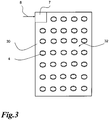
- FIG. 2 is a plan view of the wall 30 of the cabinet 3, wherein, in contrast to the execution in FIG. 1 the transmitting coil 4 in FIG. 2 extends over the entire wall 30 away. It is thus arranged over a large area on the wall 30.
- FIG. 2 can be further removed, a modulation device 7 is provided on the wall 30, which serves to modulate the supply voltage 8.
- the supply voltage supplied to the modulation device 7 is limited only by the in FIG. 2 indicated arrow indicated.
- the frequency of the supply voltage 8 is raised by the modulation device, so that the transmitting coil 4 is supplied with a higher frequency compared to the supply voltage.
- the modulation device is connected directly to the outermost turn of the transmitting coil.
- the innermost turn of the antenna coil is via a on the back 33 (see FIG. 1 ) of the wall 30 guided line 40 is also connected to the modulation device 7.
- the return line 40 to the modulation device on the front 32 (see also FIG. 1 ) of the wall 30 are guided, provided that the return line with respect to the turns of the transmitting coil 4 is isolated.
- the modulation device 7 is shown positioned in a corner of the wall 30.
- the modulation device is in turn fed with the supply voltage 8.
- the modulation device could also be positioned at a different location of the wall and also the supply of the supply voltage at a different location.
- the wall comprises 34 individual transmitting coils which are connected to the modulation device 7.
- the respective lines to the transmitting coils 4 are integrated here in the wall 30 and therefore in FIG. 3 Not shown.
- the modulation device 7 can individually and separately control the individual transmission coils and supply them with the corresponding modulated supply voltage. This makes it possible to emit energy only selectively at individual points through the respective (s) transmitting coil (s) at which an excitation of a receiving coil or receiving coils in the device 2, which is arranged in the vicinity of the wall, is required and thus carried out should. So it is a selective energy transfer only possible at these points.
- a plurality of devices on the front 33 of the wall, but possibly also on the back 32 of this, are arranged, in each case that transmitting coil (s) 4 is driven or supplied with supply voltage, which is adjacent to a receiving coil in a respective device lies / lie.
- the wall 30 as a base plate can thus be constructed modularly for the supply of one or more devices 2 with an auxiliary power, so that energy is only transmitted through the respective transmitting coil into the receiving coil where it is actually required.
- At least one transmitting coil may be provided in or on the mounting rail 31 to which the device 2 is attached.
- the arrangement for supplying the device 2 with auxiliary power in a cabinet this can of course also be provided for example in a distribution unit or in an installation housing.
- the arrangement of the at least one transmitting coil 4 takes place there in a corresponding manner in or on a wall there or in or on a fastening device provided there for the corresponding device. 2
- a distribution unit or an installation housing can still be formed many more, in each case one or more transmitting coils for emitting an introduced from a supply voltage in the transmitting coil energy and at least one receiving coil for receiving the auxiliary power to the corresponding device are provided.
- an electrical distribution unit and an installation housing such an arrangement can also be used in the same electrical structures and systems, especially when the coils are used for data transmission.
Landscapes
- Engineering & Computer Science (AREA)
- Computer Networks & Wireless Communication (AREA)
- Power Engineering (AREA)
- Charge And Discharge Circuits For Batteries Or The Like (AREA)
- Patch Boards (AREA)
Claims (7)
- Dispositif (1) d'alimentation en énergie auxiliaire d'au moins un appareil (2) dans une armoire de commande (3) ou un boîtier d'installation, dans lequel au moins une bobine d'émission (4) alimentée ou pouvant être alimentée en tension d'alimentation (8) destinée à distribuer de l'énergie auxiliaire et au moins une bobine de réception (5) destinée à recevoir l'énergie auxiliaire sont prévues et l'au moins une bobine d'émission (4) est disposée dans ou sur l'armoire de commande (3) ou le boîtier d'installation ainsi qu'au moins un élément de base (30, 31) dans la ou de l'armoire de commande (3) ou du boîtier d'installation est prévu, lequel est pourvu de l'au moins une bobine d'émission (4) alimentée ou pouvant être alimentée en tension d'alimentation (8),
dans lequel l'élément de base (30, 31) est conçu de manière modulaire pour la réception de plusieurs bobines d'émission (4) de telle manière qu'une alimentation en énergie sélective soit prévue dans les modules individuels par commande de bobines d'émission individuelles intégrées dans l'élément de base (30, 31) et ainsi une excitation ciblée d'une bobine de réception ou de bobines de réception dans l'appareil à alimenter, et l'élément de base est une plaque de base (30) dans la ou de l'armoire de commande (3) ou du boîtier d'installation ou un dispositif de fixation, lequel est un rail porteur (31) pour l'appareil (2), dans ou sur l'armoire de commande (3) ou le boîtier d'installation. - Dispositif (1) selon la revendication 1,
caractérisé en ce que
la bobine de réception (5) est intégrée dans l'appareil (2). - Dispositif (1) selon l'une quelconque des revendications précédentes,
caractérisé en ce que
au moins un dispositif d'alimentation (6) pour l'appareil (2) est prévu et la bobine de réception (5) est raccordée ou peut être raccordée au dispositif d'alimentation (6). - Dispositif (1) selon l'une quelconque des revendications 1 à 3,
caractérisé en ce que
au moins un dispositif de raccordement pour l'au moins une bobine d'émission (4) est prévu dans l'élément de base (30, 31). - Dispositif (1) selon l'une quelconque des revendications 1 à 4,
caractérisé en ce que
la bobine d'émission (4) et/ou la bobine de réception (5) peut être utilisée pour la transmission de données. - Dispositif (1) selon la revendication 5,
caractérisé en ce que
au moins un dispositif pour l'injection de données dans la bobine d'émission (4) et/ou au moins un dispositif pour le traitement de données reçues par la bobine de réception (5) est prévu. - Dispositif (1) selon la revendication 6,
caractérisé en ce que
le dispositif pour l'injection de données dans la bobine d'émission (4) est agencé dans la zone du ou sur l'élément de base (30, 31) et/ou le dispositif pour le traitement de données reçues par la bobine de réception (5) est agencé dans l'appareil (2) ou dans la zone de l'appareil (2).
Applications Claiming Priority (2)
| Application Number | Priority Date | Filing Date | Title |
|---|---|---|---|
| DE102008011920A DE102008011920A1 (de) | 2008-02-29 | 2008-02-29 | Anordnung zum Versorgen zumindest eines Gerätes in einem Schaltschrank, einer Verteilereinheit oder einem Installationsgehäuse mit Hilfsenergie |
| PCT/EP2009/001219 WO2009106266A2 (fr) | 2008-02-29 | 2009-02-20 | Dispositif d'alimentation en énergie auxiliaire d'au moins un appareil dans une armoire de commande, un tableau de distribution ou un boîtier d'installation |
Publications (2)
| Publication Number | Publication Date |
|---|---|
| EP2248242A2 EP2248242A2 (fr) | 2010-11-10 |
| EP2248242B1 true EP2248242B1 (fr) | 2018-04-04 |
Family
ID=40936101
Family Applications (1)
| Application Number | Title | Priority Date | Filing Date |
|---|---|---|---|
| EP09714995.9A Active EP2248242B1 (fr) | 2008-02-29 | 2009-02-20 | Dispositif d'alimentation en énergie auxiliaire d'au moins un appareil dans une armoire de commande ou un boîtier d'installation |
Country Status (3)
| Country | Link |
|---|---|
| EP (1) | EP2248242B1 (fr) |
| DE (1) | DE102008011920A1 (fr) |
| WO (1) | WO2009106266A2 (fr) |
Families Citing this family (3)
| Publication number | Priority date | Publication date | Assignee | Title |
|---|---|---|---|---|
| DE102010036061A1 (de) * | 2010-09-01 | 2012-03-01 | Airbus Operations Gmbh | System zur kontaktlosen Energieübertragung |
| DE102014219572A1 (de) * | 2014-09-26 | 2016-03-31 | Phoenix Contact Gmbh & Co. Kg | System mit aneinander-reihbaren Elektronikmodulen |
| DE202016101181U1 (de) * | 2016-03-04 | 2017-06-07 | Ipek International Gmbh | Rohrinspektions- und/oder Wartungseinrichtung |
Citations (1)
| Publication number | Priority date | Publication date | Assignee | Title |
|---|---|---|---|---|
| DE19882578B4 (de) * | 1997-08-04 | 2008-07-24 | Autoliv Development Ab | Sicherheitsvorrichtung zur Verwendung in einem Kraftfahrzeug |
Family Cites Families (8)
| Publication number | Priority date | Publication date | Assignee | Title |
|---|---|---|---|---|
| DE19705301C1 (de) | 1997-02-13 | 1998-10-01 | V W B Gmbh | Einrichtung zur berührungslosen Informations- und Energieübertragung |
| DE50014389D1 (de) | 1999-06-11 | 2007-07-19 | Abb Research Ltd | System für eine vielzahl von näherungssensoren aufweisende maschine sowie näherungssensor und primärwicklung hierzu |
| DE19926562A1 (de) | 1999-06-11 | 2000-12-14 | Abb Research Ltd | Verfahren und Anordnung zur drahtlosen Versorgung einer Vielzahl Aktoren mit elektrischer Energie, Aktor hierzu sowie System für eine eine Vielzahl von Aktoren aufweisende Maschine |
| JP2003502993A (ja) | 1999-06-11 | 2003-01-21 | アーベーベー・リサーチ・リミテッド | ワイヤを使用することなく多数のアクチュエータに電力を供給する方法及び装置、本目的のためのアクチュエータ及び一次巻き線、並びに多数のアクチュエータを有する機械のためのシステム |
| US7612528B2 (en) | 1999-06-21 | 2009-11-03 | Access Business Group International Llc | Vehicle interface |
| FR2812962B1 (fr) * | 2000-08-08 | 2004-09-24 | Schneider Electric Ind Sa | Appareil electrique comportant un dispositif de controle, support et dispositif de surveillance pour un tel appareil, et installation electrique les comportant |
| CN1922700A (zh) | 2003-02-04 | 2007-02-28 | 通达商业集团国际公司 | 感应线圈组件 |
| DE10304587A1 (de) | 2003-02-05 | 2004-08-19 | Abb Research Ltd. | Magnetfelderzeugungssystem mit einer mindestens zweidimensionalen Wicklungsanordnung |
-
2008
- 2008-02-29 DE DE102008011920A patent/DE102008011920A1/de not_active Ceased
-
2009
- 2009-02-20 WO PCT/EP2009/001219 patent/WO2009106266A2/fr active Application Filing
- 2009-02-20 EP EP09714995.9A patent/EP2248242B1/fr active Active
Patent Citations (1)
| Publication number | Priority date | Publication date | Assignee | Title |
|---|---|---|---|---|
| DE19882578B4 (de) * | 1997-08-04 | 2008-07-24 | Autoliv Development Ab | Sicherheitsvorrichtung zur Verwendung in einem Kraftfahrzeug |
Also Published As
| Publication number | Publication date |
|---|---|
| WO2009106266A2 (fr) | 2009-09-03 |
| DE102008011920A1 (de) | 2009-09-10 |
| WO2009106266A3 (fr) | 2010-03-04 |
| EP2248242A2 (fr) | 2010-11-10 |
Similar Documents
| Publication | Publication Date | Title |
|---|---|---|
| EP1275208B1 (fr) | Dispositif de transmission sans contact de signaux electriques ou d'energie electrique | |
| EP1186087B1 (fr) | Systeme destine a une machine presentant plusieurs detecteurs de proximite et detecteurs de proximite et enroulement de circuit primaire utilises dans ce systeme | |
| EP2803143B1 (fr) | Dispositif d'alimentation en énergie inductive | |
| EP3776807B1 (fr) | Système de transport linéaire et système de transmission d'énergie et de données sans contact | |
| DE102013110341B4 (de) | Drahtlose Leistungsübertragungsvorrichtung und Direktantriebssystem mit der Vorrichtung | |
| EP1763449B1 (fr) | Systeme de transport guide | |
| DE102011014752B4 (de) | System zum berührungslosen Übertragen von Energie an ein Fahrzeug | |
| EP1294074A2 (fr) | Système de génération d'un champ magnétique et dispositif pour l'alimantation sans fil d'une pluralité de senseurs et/ou actionneurs | |
| DE102016215212A1 (de) | Bewegungsvorrichtung mit magnetischer Positionsbestimmung und Datenübertragungsvorrichtung | |
| EP2263194A1 (fr) | Structure d' antenne avec au moins deux bobines-antennes; composant rf pour la transmission sans contact d' énergie et de données; appareil électronique avec composant rf | |
| EP2248242B1 (fr) | Dispositif d'alimentation en énergie auxiliaire d'au moins un appareil dans une armoire de commande ou un boîtier d'installation | |
| EP2803142B1 (fr) | Système de données modulaire avec transmission d'énergie par induction | |
| DE102010001484A1 (de) | Übertragungsvorrichtung zur kontaktlosen Übertragung von Energie und Daten, Übertragungssystem und Verfahren zur kontaktlosen induktiven Energieübertragung und Datenübertragung | |
| DE102005013293B4 (de) | Magnetresonanzanlage mit einer Hochfrequenzquelle | |
| DE19926562A1 (de) | Verfahren und Anordnung zur drahtlosen Versorgung einer Vielzahl Aktoren mit elektrischer Energie, Aktor hierzu sowie System für eine eine Vielzahl von Aktoren aufweisende Maschine | |
| DE102008031534B4 (de) | Transponder und Anordnung mit einem solchen Transponder | |
| DE102010062462A1 (de) | Antennensystem, Sendeanordnung und Verfahren zum Betrieb einer Sendeanordnung | |
| EP0964803B1 (fr) | Unite emettrice, notamment pour un systeme antivol d'un vehicule a moteur | |
| DE102014102936A1 (de) | Elektronische Baugruppe mit interner Nahfeldkommunikation | |
| DE102005030084B4 (de) | Spurgeführtes Transportfahrzeug mit Hebebühne und Energiespeicher | |
| DE102018201814B4 (de) | Gehäuse mit einer Energieübertragungsspule und die zur Energieübertragung erforderlichen elektronischen Schaltungen | |
| DE102014221568A1 (de) | Transformator und Verfahren zum Betrieb eines Transformators | |
| DE10321842B3 (de) | Verfahren und Vorrichtung zum Betrieb eines Sensors oder Aktors | |
| WO2022258566A1 (fr) | Procédé de transfert d'énergie par induction | |
| DE10304587A1 (de) | Magnetfelderzeugungssystem mit einer mindestens zweidimensionalen Wicklungsanordnung |
Legal Events
| Date | Code | Title | Description |
|---|---|---|---|
| PUAI | Public reference made under article 153(3) epc to a published international application that has entered the european phase |
Free format text: ORIGINAL CODE: 0009012 |
|
| 17P | Request for examination filed |
Effective date: 20100928 |
|
| AK | Designated contracting states |
Kind code of ref document: A2 Designated state(s): AT BE BG CH CY CZ DE DK EE ES FI FR GB GR HR HU IE IS IT LI LT LU LV MC MK MT NL NO PL PT RO SE SI SK TR |
|
| AX | Request for extension of the european patent |
Extension state: AL BA RS |
|
| DAX | Request for extension of the european patent (deleted) | ||
| 17Q | First examination report despatched |
Effective date: 20111116 |
|
| RAP1 | Party data changed (applicant data changed or rights of an application transferred) |
Owner name: EATON ELECTRICAL IP GMBH & CO. KG |
|
| STAA | Information on the status of an ep patent application or granted ep patent |
Free format text: STATUS: EXAMINATION IS IN PROGRESS |
|
| REG | Reference to a national code |
Ref country code: DE Ref legal event code: R079 Ref document number: 502009014865 Country of ref document: DE Free format text: PREVIOUS MAIN CLASS: H02J0005000000 Ipc: H02J0050100000 |
|
| GRAP | Despatch of communication of intention to grant a patent |
Free format text: ORIGINAL CODE: EPIDOSNIGR1 |
|
| STAA | Information on the status of an ep patent application or granted ep patent |
Free format text: STATUS: GRANT OF PATENT IS INTENDED |
|
| RIC1 | Information provided on ipc code assigned before grant |
Ipc: H01F 38/14 20060101ALN20170914BHEP Ipc: H02J 50/10 20160101AFI20170914BHEP Ipc: H02J 50/40 20160101ALI20170914BHEP |
|
| INTG | Intention to grant announced |
Effective date: 20171011 |
|
| GRAS | Grant fee paid |
Free format text: ORIGINAL CODE: EPIDOSNIGR3 |
|
| GRAA | (expected) grant |
Free format text: ORIGINAL CODE: 0009210 |
|
| STAA | Information on the status of an ep patent application or granted ep patent |
Free format text: STATUS: THE PATENT HAS BEEN GRANTED |
|
| AK | Designated contracting states |
Kind code of ref document: B1 Designated state(s): AT BE BG CH CY CZ DE DK EE ES FI FR GB GR HR HU IE IS IT LI LT LU LV MC MK MT NL NO PL PT RO SE SI SK TR |
|
| REG | Reference to a national code |
Ref country code: GB Ref legal event code: FG4D Free format text: NOT ENGLISH |
|
| REG | Reference to a national code |
Ref country code: CH Ref legal event code: EP |
|
| REG | Reference to a national code |
Ref country code: AT Ref legal event code: REF Ref document number: 986597 Country of ref document: AT Kind code of ref document: T Effective date: 20180415 |
|
| REG | Reference to a national code |
Ref country code: DE Ref legal event code: R096 Ref document number: 502009014865 Country of ref document: DE |
|
| REG | Reference to a national code |
Ref country code: IE Ref legal event code: FG4D Free format text: LANGUAGE OF EP DOCUMENT: GERMAN |
|
| REG | Reference to a national code |
Ref country code: NL Ref legal event code: MP Effective date: 20180404 |
|
| REG | Reference to a national code |
Ref country code: LT Ref legal event code: MG4D |
|
| PG25 | Lapsed in a contracting state [announced via postgrant information from national office to epo] |
Ref country code: NL Free format text: LAPSE BECAUSE OF FAILURE TO SUBMIT A TRANSLATION OF THE DESCRIPTION OR TO PAY THE FEE WITHIN THE PRESCRIBED TIME-LIMIT Effective date: 20180404 |
|
| PG25 | Lapsed in a contracting state [announced via postgrant information from national office to epo] |
Ref country code: SE Free format text: LAPSE BECAUSE OF FAILURE TO SUBMIT A TRANSLATION OF THE DESCRIPTION OR TO PAY THE FEE WITHIN THE PRESCRIBED TIME-LIMIT Effective date: 20180404 Ref country code: PL Free format text: LAPSE BECAUSE OF FAILURE TO SUBMIT A TRANSLATION OF THE DESCRIPTION OR TO PAY THE FEE WITHIN THE PRESCRIBED TIME-LIMIT Effective date: 20180404 Ref country code: FI Free format text: LAPSE BECAUSE OF FAILURE TO SUBMIT A TRANSLATION OF THE DESCRIPTION OR TO PAY THE FEE WITHIN THE PRESCRIBED TIME-LIMIT Effective date: 20180404 Ref country code: BG Free format text: LAPSE BECAUSE OF FAILURE TO SUBMIT A TRANSLATION OF THE DESCRIPTION OR TO PAY THE FEE WITHIN THE PRESCRIBED TIME-LIMIT Effective date: 20180704 Ref country code: NO Free format text: LAPSE BECAUSE OF FAILURE TO SUBMIT A TRANSLATION OF THE DESCRIPTION OR TO PAY THE FEE WITHIN THE PRESCRIBED TIME-LIMIT Effective date: 20180704 Ref country code: LT Free format text: LAPSE BECAUSE OF FAILURE TO SUBMIT A TRANSLATION OF THE DESCRIPTION OR TO PAY THE FEE WITHIN THE PRESCRIBED TIME-LIMIT Effective date: 20180404 Ref country code: ES Free format text: LAPSE BECAUSE OF FAILURE TO SUBMIT A TRANSLATION OF THE DESCRIPTION OR TO PAY THE FEE WITHIN THE PRESCRIBED TIME-LIMIT Effective date: 20180404 |
|
| PG25 | Lapsed in a contracting state [announced via postgrant information from national office to epo] |
Ref country code: GR Free format text: LAPSE BECAUSE OF FAILURE TO SUBMIT A TRANSLATION OF THE DESCRIPTION OR TO PAY THE FEE WITHIN THE PRESCRIBED TIME-LIMIT Effective date: 20180705 Ref country code: LV Free format text: LAPSE BECAUSE OF FAILURE TO SUBMIT A TRANSLATION OF THE DESCRIPTION OR TO PAY THE FEE WITHIN THE PRESCRIBED TIME-LIMIT Effective date: 20180404 Ref country code: HR Free format text: LAPSE BECAUSE OF FAILURE TO SUBMIT A TRANSLATION OF THE DESCRIPTION OR TO PAY THE FEE WITHIN THE PRESCRIBED TIME-LIMIT Effective date: 20180404 |
|
| PG25 | Lapsed in a contracting state [announced via postgrant information from national office to epo] |
Ref country code: PT Free format text: LAPSE BECAUSE OF FAILURE TO SUBMIT A TRANSLATION OF THE DESCRIPTION OR TO PAY THE FEE WITHIN THE PRESCRIBED TIME-LIMIT Effective date: 20180806 |
|
| REG | Reference to a national code |
Ref country code: DE Ref legal event code: R097 Ref document number: 502009014865 Country of ref document: DE |
|
| PG25 | Lapsed in a contracting state [announced via postgrant information from national office to epo] |
Ref country code: RO Free format text: LAPSE BECAUSE OF FAILURE TO SUBMIT A TRANSLATION OF THE DESCRIPTION OR TO PAY THE FEE WITHIN THE PRESCRIBED TIME-LIMIT Effective date: 20180404 Ref country code: CZ Free format text: LAPSE BECAUSE OF FAILURE TO SUBMIT A TRANSLATION OF THE DESCRIPTION OR TO PAY THE FEE WITHIN THE PRESCRIBED TIME-LIMIT Effective date: 20180404 Ref country code: EE Free format text: LAPSE BECAUSE OF FAILURE TO SUBMIT A TRANSLATION OF THE DESCRIPTION OR TO PAY THE FEE WITHIN THE PRESCRIBED TIME-LIMIT Effective date: 20180404 Ref country code: DK Free format text: LAPSE BECAUSE OF FAILURE TO SUBMIT A TRANSLATION OF THE DESCRIPTION OR TO PAY THE FEE WITHIN THE PRESCRIBED TIME-LIMIT Effective date: 20180404 Ref country code: SK Free format text: LAPSE BECAUSE OF FAILURE TO SUBMIT A TRANSLATION OF THE DESCRIPTION OR TO PAY THE FEE WITHIN THE PRESCRIBED TIME-LIMIT Effective date: 20180404 |
|
| PLBE | No opposition filed within time limit |
Free format text: ORIGINAL CODE: 0009261 |
|
| STAA | Information on the status of an ep patent application or granted ep patent |
Free format text: STATUS: NO OPPOSITION FILED WITHIN TIME LIMIT |
|
| PG25 | Lapsed in a contracting state [announced via postgrant information from national office to epo] |
Ref country code: IT Free format text: LAPSE BECAUSE OF FAILURE TO SUBMIT A TRANSLATION OF THE DESCRIPTION OR TO PAY THE FEE WITHIN THE PRESCRIBED TIME-LIMIT Effective date: 20180404 |
|
| 26N | No opposition filed |
Effective date: 20190107 |
|
| PG25 | Lapsed in a contracting state [announced via postgrant information from national office to epo] |
Ref country code: SI Free format text: LAPSE BECAUSE OF FAILURE TO SUBMIT A TRANSLATION OF THE DESCRIPTION OR TO PAY THE FEE WITHIN THE PRESCRIBED TIME-LIMIT Effective date: 20180404 |
|
| REG | Reference to a national code |
Ref country code: CH Ref legal event code: PL |
|
| GBPC | Gb: european patent ceased through non-payment of renewal fee |
Effective date: 20190220 |
|
| PG25 | Lapsed in a contracting state [announced via postgrant information from national office to epo] |
Ref country code: MC Free format text: LAPSE BECAUSE OF FAILURE TO SUBMIT A TRANSLATION OF THE DESCRIPTION OR TO PAY THE FEE WITHIN THE PRESCRIBED TIME-LIMIT Effective date: 20180404 Ref country code: LU Free format text: LAPSE BECAUSE OF NON-PAYMENT OF DUE FEES Effective date: 20190220 |
|
| REG | Reference to a national code |
Ref country code: BE Ref legal event code: MM Effective date: 20190228 |
|
| REG | Reference to a national code |
Ref country code: IE Ref legal event code: MM4A |
|
| PG25 | Lapsed in a contracting state [announced via postgrant information from national office to epo] |
Ref country code: LI Free format text: LAPSE BECAUSE OF NON-PAYMENT OF DUE FEES Effective date: 20190228 Ref country code: CH Free format text: LAPSE BECAUSE OF NON-PAYMENT OF DUE FEES Effective date: 20190228 |
|
| PG25 | Lapsed in a contracting state [announced via postgrant information from national office to epo] |
Ref country code: IE Free format text: LAPSE BECAUSE OF NON-PAYMENT OF DUE FEES Effective date: 20190220 Ref country code: GB Free format text: LAPSE BECAUSE OF NON-PAYMENT OF DUE FEES Effective date: 20190220 |
|
| PG25 | Lapsed in a contracting state [announced via postgrant information from national office to epo] |
Ref country code: BE Free format text: LAPSE BECAUSE OF NON-PAYMENT OF DUE FEES Effective date: 20190228 Ref country code: FR Free format text: LAPSE BECAUSE OF NON-PAYMENT OF DUE FEES Effective date: 20190228 |
|
| PG25 | Lapsed in a contracting state [announced via postgrant information from national office to epo] |
Ref country code: TR Free format text: LAPSE BECAUSE OF FAILURE TO SUBMIT A TRANSLATION OF THE DESCRIPTION OR TO PAY THE FEE WITHIN THE PRESCRIBED TIME-LIMIT Effective date: 20180404 |
|
| REG | Reference to a national code |
Ref country code: AT Ref legal event code: MM01 Ref document number: 986597 Country of ref document: AT Kind code of ref document: T Effective date: 20190220 |
|
| PG25 | Lapsed in a contracting state [announced via postgrant information from national office to epo] |
Ref country code: AT Free format text: LAPSE BECAUSE OF NON-PAYMENT OF DUE FEES Effective date: 20190220 |
|
| PG25 | Lapsed in a contracting state [announced via postgrant information from national office to epo] |
Ref country code: MT Free format text: LAPSE BECAUSE OF FAILURE TO SUBMIT A TRANSLATION OF THE DESCRIPTION OR TO PAY THE FEE WITHIN THE PRESCRIBED TIME-LIMIT Effective date: 20180404 |
|
| PG25 | Lapsed in a contracting state [announced via postgrant information from national office to epo] |
Ref country code: CY Free format text: LAPSE BECAUSE OF FAILURE TO SUBMIT A TRANSLATION OF THE DESCRIPTION OR TO PAY THE FEE WITHIN THE PRESCRIBED TIME-LIMIT Effective date: 20180404 |
|
| PG25 | Lapsed in a contracting state [announced via postgrant information from national office to epo] |
Ref country code: IS Free format text: LAPSE BECAUSE OF FAILURE TO SUBMIT A TRANSLATION OF THE DESCRIPTION OR TO PAY THE FEE WITHIN THE PRESCRIBED TIME-LIMIT Effective date: 20180804 |
|
| PG25 | Lapsed in a contracting state [announced via postgrant information from national office to epo] |
Ref country code: HU Free format text: LAPSE BECAUSE OF FAILURE TO SUBMIT A TRANSLATION OF THE DESCRIPTION OR TO PAY THE FEE WITHIN THE PRESCRIBED TIME-LIMIT; INVALID AB INITIO Effective date: 20090220 |
|
| PG25 | Lapsed in a contracting state [announced via postgrant information from national office to epo] |
Ref country code: MK Free format text: LAPSE BECAUSE OF FAILURE TO SUBMIT A TRANSLATION OF THE DESCRIPTION OR TO PAY THE FEE WITHIN THE PRESCRIBED TIME-LIMIT Effective date: 20180404 |
|
| PGFP | Annual fee paid to national office [announced via postgrant information from national office to epo] |
Ref country code: DE Payment date: 20230119 Year of fee payment: 15 |
|
| P01 | Opt-out of the competence of the unified patent court (upc) registered |
Effective date: 20230521 |