EP2247947B1 - Vorrichtung zur überwachung von mehrkabelsystemem - Google Patents
Vorrichtung zur überwachung von mehrkabelsystemem Download PDFInfo
- Publication number
- EP2247947B1 EP2247947B1 EP09715449.6A EP09715449A EP2247947B1 EP 2247947 B1 EP2247947 B1 EP 2247947B1 EP 09715449 A EP09715449 A EP 09715449A EP 2247947 B1 EP2247947 B1 EP 2247947B1
- Authority
- EP
- European Patent Office
- Prior art keywords
- cables
- magnetic
- housing
- hall
- monitoring
- Prior art date
- Legal status (The legal status is an assumption and is not a legal conclusion. Google has not performed a legal analysis and makes no representation as to the accuracy of the status listed.)
- Active
Links
Images


Classifications
-
- G—PHYSICS
- G01—MEASURING; TESTING
- G01N—INVESTIGATING OR ANALYSING MATERIALS BY DETERMINING THEIR CHEMICAL OR PHYSICAL PROPERTIES
- G01N27/00—Investigating or analysing materials by the use of electric, electrochemical, or magnetic means
- G01N27/72—Investigating or analysing materials by the use of electric, electrochemical, or magnetic means by investigating magnetic variables
- G01N27/82—Investigating or analysing materials by the use of electric, electrochemical, or magnetic means by investigating magnetic variables for investigating the presence of flaws
- G01N27/83—Investigating or analysing materials by the use of electric, electrochemical, or magnetic means by investigating magnetic variables for investigating the presence of flaws by investigating stray magnetic fields
Definitions
- the present invention relates to the field of monitoring of cables, in particular metal cables, in multicable systems for plants or systems for moving objects.
- Metal cables find a wide use in systems for moving objects, such as, for example, lifting systems (hoists, elevators, etc.) and systems for skiing purposes, i.e., in systems characterized by difficult conditions of operation both from the environmental standpoint and from the standpoint of mechanical stress.
- lifting systems hoists, elevators, etc.
- systems for skiing purposes i.e., in systems characterized by difficult conditions of operation both from the environmental standpoint and from the standpoint of mechanical stress.
- the considerable attention to the subject of safety and the continuous need to meet to increasingly stringent technical requirements make the problem of monitoring of metal cables, which represent one of the weak links in the chain of safety made up of these transport systems, particularly felt.
- these devices are based upon setting-up of a magnetic circuit, i.e., a closed path for the magnetic flux, which comprises the cable to be monitored and which is consequently affected by cracks or incisions in the cable itself, so that the magnetic characteristics of the magnetic circuit are indicative of the state of the cable.
- a magnetic circuit i.e., a closed path for the magnetic flux
- these devices comprise magnetic-field sensors of two different types: sensors adapted to measure the losses of magnetic flux due to local faults (LFs) in the cable, which are generally located in the proximity of the path set up for the magnetic flux, or sensors adapted to measure variations of magnetic flux due to losses of metallic area (LMA) in the cable, the latter sensors being generally located along the path set up for the magnetic flux.
- LFs local faults
- LMA metallic area
- Monitoring devices of known type have certain drawbacks.
- the difficulty in controlling precisely the dispersed magnetic fluxes, and the relativity of the position of the sensors with respect to the position of the faults in the cable section reduce the precision and reliability of monitoring of said faults.
- a further drawback is linked to the encumbrance of said devices, as well as to the need to provide an adequate power supply, mainly in the case, which is not infrequent in literature, of devices in which the magnetic field is not generated by permanent magnets, but rather by current windings.
- the object of the present invention is to provide a device capable of overcoming at least in part the drawbacks of the prior art.
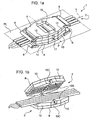
- Figures 1a, 1b , and 2 show a monitoring device 1 for a multicable system, and a bunch 2 of cables 3 undergoing measurement, for example, comprising a number of cables equal to four.
- the multicable system forms part of a lifting system, for example for lifting the cabin of an elevator, or a driving system, for example, for driving a cableway-car.
- the system comprises a motor assembly and a pulley coupled thereto, adapted to move the bunch 2 of cables 3.
- the monitoring device 1 is preferably coupled to the pulley by means of suitable coupling elements with which it is provided.
- the monitoring device 1 comprises a top shell 4 and a bottom shell 5, facing each other on opposite sides with respect to the longitudinal plane PL, and adapted to be engaged in a releasable way to the cables, in such a way that the cables 3 to be monitored can run in a portion of space comprised between the top shell 4 and the bottom shell 5.
- the running of the cables 3 is facilitated by the presence of rollers 6 connected to the top shell 4 and the bottom shell 5 of the monitoring device 1.
- top shell 4 and the bottom shell 5 are joined by a hinge (not shown in Figures 1a and 1b ) set in a direction substantially parallel with respect to the longitudinal axis L; in addition, the top shell 4 closes on the bottom shell 5 by means of an appropriate closing assembly (not shown in Figures 1a and 1b ), which enables to keep the monitoring device 1 closed during the monitoring operations.
- Each of the top shell 4 and bottom shell 5 comprise an external metal structure 8, made of ferromagnetic material, and a housing structure 9, having a mechanical supporting function, which are set on top of one another.
- the housing structure 9 of each of the top shell 4 and bottom shell 5 is constituted by a pair of housing elements 10.
- the housing elements 10, for example made of plastic material or other nonmagnetic material, are the same as one another, and, when the monitoring device 1 is closed in a monitoring condition, are set specularly with respect to a perpendicular axis P, orthogonal to the longitudinal axis L.
- Each housing element 10 has: a top face 10a and a bottom face 10b, which, when the monitoring device 1 is closed, are set substantially parallel to the longitudinal plane PL, the top face 10a being, of the two faces considered, the one that is farther from the longitudinal plane PL; and moreover an internal lateral face 10c, which, again when the monitoring device 1 is closed, is perpendicular to the longitudinal axis L.
- each housing element 10 is shaped so as to define, on its own bottom face 10b, a plurality of recesses 12, of a substantially semicylindrical shape, facing the longitudinal plane PL.
- the recesses 12 of the top shell 4 define, with corresponding recesses 12 of the bottom shell 5, cylindrical channels in which the cables 3 to be monitored can run.
- each housing element 10 On the top face 10a of each housing element 10 there is defined a seat 14 facing the corresponding external metallic structure 8. In each of said seats 14 there is housed a permanent magnet 15.
- the housing elements 10 of the top shell 4 and bottom shell 5 are arranged so as to define a compartment 17, partially occupied by the cables 3 and delimited at the sides by the internal lateral faces 10c of the housing elements 10.
- Each of the external metal structures 8 has a through cavity 18, which is set centrally and in correspondence with the compartment 17 having, for example, the shape of a parallelepiped, even though other geometries are equally possible.
- the presence of the through cavity 18 makes the surface of the external metal structures not simply connected.
- the monitoring device 1 further comprises a first and a second electronic printed circuit 20a, 20b (shown in Figure 3 ), housed, in use, within the compartment 17, and set on opposite sides with respect to the longitudinal plane PL, to which they are basically perpendicular.
- a first and a second electronic printed circuit 20a, 20b shown in Figure 3
- the electronic printed circuits 20a, 20b there are set Hall-effect sensors 21, arranged to form top half-crowns 22 and bottom half-crowns 23, respectively, on the first and second electronic printed circuits 20a, 20b, set in such a way as to form a first linear array and a second linear array of half-crowns of sensors.
- Each of the electronic printed circuits 20a, 20b has a plurality of notches 24 of semicircular shape (in particular, in a number equal to the number of recesses 12 and cables 3 to be monitored), around which there are located corresponding top half-crowns 22 or bottom half-crowns 23 of Hall-effect sensors 21.
- the corresponding notches 24 of the first and the second electronic printed circuits 20a, 20b define seats through which respective cables 3 run.
- top half-crowns 22 and bottom half-crowns 23 form respective crowns 26 of Hall-effect sensors 21; in this way, each cable 3 passes through a corresponding crown 26.
- Top half-crowns 22 and bottom half-crowns 23 forming part of a same crown 26 are electrically connected by means of electrical wires 27, comprising amongst other things a supply line and a ground line.
- the number and arrangement of the Hall-effect sensors 21 within each crown 26 are such that the angular distance between a potential fault in any point of the section of a cable 3 and the Hall-effect sensor 21 closest to the fault itself is always such as to guarantee an effective detection of the fault.
- the Hall-effect sensors 21 are able to detect in an optimal way a potential fault in the cable 3 only if the fault is at an angular distance not greater than 90° from the sensor itself; consequently, the number of Hall-effect sensors 21 forming each crown 26 is not less than four.
- each crown 26 comprise a number of Hall-effect sensors 21 equal to eight; alternatively, as shown in the next Figure 5b , each crown 26 comprises a number of Hall-effect sensors 21 equal to ten, angularly evenly spaced along the profile of the crown 26.
- the principle of operation of the monitoring device 1 described is based on the fact that, leaving the housing structure 9 apart, the function of which is purely mechanical and for the limitation of the vibrations, and considering for simplicity the case of a single cable 3, the permanent magnets 15, the external metallic structures 8 and the cable 3 to be monitored define a magnetic circuit, as represented in Figure 4 .
- the magnetic flux created by the permanent magnets 15 is canalized inside the cable 3, bringing it into well-defined magnetic working conditions, in particular in a condition of magnetic saturation.
- the magnetic flux closes through the external metal structures 8, which have magnetic and geometrical characteristics such as to guarantee the confinement of the magnetic flux within the cable 3 to be monitored, thus reducing the dispersed magnetic flux.
- the presence of the through cavity 18 allows optimizing the path of the magnetic fluxes, i.e., the closing of the magnetic circuits corresponding to the cables 3 to be monitored, and in particular: optimizing of the confinement of the magnetic flux within the cables 3, bringing them to the maximum saturation induction; and reducing the magnetic flux dispersed in the proximity of the Hall-effect sensors 21, in the absence of faults in the cables 3.
- the magnetic flux is altered by the presence of the fault itself.
- This alteration of the magnetic flux is detected by one or more Hall-effect sensors 21, which form part of the crown 26 corresponding to the cable 3 being measured.
- the Hall-effect sensors 21, which are configured in such a way as to detect the radial component B z of the dispersed magnetic field, generate a detection signal, whose analysis enables to trace back the presence of the fault.
- the dispersed magnetic fluxes are minimal.
- the reduction of the dispersed magnetic fluxes enables to obtain a greater magnetic saturation of the cables 3, and hence to obtain detection signals sufficiently ample even in the case of faults within the cables 3.
- the reduction of the dispersed magnetic fluxes makes the magnetic field close to the Hall-effect sensors 21 practically zero (in the absence of faults), with consequent reduction of the jams due, for example, to oscillations of the cables 3, enabling to increase the sensitivity of the monitoring device 1.
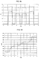
- Figures 6a and 6b show, respectively, the magnitude of the magnetic induction B and the magnitude of the magnetic field along an axis orthogonal to the longitudinal axis L and belonging to the longitudinal plane PL in which the cables 3 lie, highlighting an increase of the magnetic induction B and of the magnetic field in correspondence with the cables 3 and in the presence of the external metallic structures 8 provided with through cavities 18.
- Figure 6c shows the trend of the relative magnetic permeability ⁇ r along the aforesaid orthogonal axis, highlighting a greater magnetic saturation of the cables 3 in the structure according to the invention.
- Figure 6d shows the trend of the radial component B z of the magnetic induction B along a portion of the longitudinal axis L comprised between the permanent magnets 15, highlighting a reduction of said component due to the dispersed fluxes in the absence of faults of the cables 3.
- the reduction of the radial component B z detected by the Hall-effect sensors 21, enables a better signal-to-noise ratio to be obtained in the detection of the faults, in the presence of jams.
- the monitoring device 1 described enables monitoring multicable systems, detecting the faults of the individual cables 3 in a selective way: each cable 3 is analysed independently of the others, thus avoiding any uncertainty in localizing of the faults, by means of analysis of the detection signals produced by the Hall-effect sensors 21 of the respective crown 26.
- said detection signals are appropriately integrated in such a way as to generate a single output signal of the crown 26, commonly known as localized-fault signal (or more briefly, LF signal).
- the potential fault in a faulty cable 3 is detected preferentially by the corresponding crown 26, generating at the output from said crown 26 an LF signal of greater amplitude with respect to the LF signals generated at the output by the other crowns 26.
- FIG. 7 a processing circuit, designated by 30, of the monitoring device 1, which is adapted to receive and process the output LF signals from the crowns 26.
- the acquisition circuit 30 is integrated in electronic printed circuits 20a, 20b.
- Figure 7 refers to the case of a monitoring device 1 capable of monitoring a number n of cables 3, hence provided with n crowns 26 of Hall-effect sensors 21.
- the processing circuit 30 comprises: n conditioning stages 31, which are connected to corresponding crowns 26; a logic unit 32, in the case in point a microcontroller (or else a DSP), having at input a multichannel A/D converter (not shown in Figure 7 ) and receiving at input the outputs of the conditioning stages 31; a serial interface 33, connected to the output of the logic unit 32; and warning means 34, which are also connected to the output of the logic unit 32 and are adapted to issue warning signals (light signals, acoustic signals, etc.).
- the conditioning stages 31 adapt the LF signals coming from the crowns 26 in such a way that these will meet the requirements needed at input of the logic unit 32.
- the logic unit 32 sends the signals, appropriately processed, to the serial interface 33 and/or to the warning means 34.
- the signals processed by the logic unit 32 and sent to the serial interface 33 can be further processed by an external computer (not shown in Figure 7 ), after prior connection of the serial interface 33 with an external interfacing bus.
- the logic unit 32 is configured for detecting the overstepping, by the LF signals produced by the crowns 26, of a given threshold value, which can be set from outside the monitoring device 1 and is stored in the logic unit 32 itself, or else in an associated memory (not shown in Figure 7 ).
- the monitoring device 1 can supply an output signal corresponding to the state of the cables 3 in different forms.
- the output signal can consist of a light signal, for example the lighting of a LED by warning means 34, to indicate a fault in a given cable 3.
- the output signal can consist of the complete traces produced by the crowns 26, i.e., of the LF signals produced by the crowns 26 during the entire monitoring. These traces must be analysed with the aid of an external processor, which is connected to the monitoring device 1 by means of connection to the serial interface 33.
- the output signal can consist of alarm and diagnostic signals, which can be transmitted to a control centre external to the monitoring device 1, for example by means of a wireless network, or else by exploiting possible pre-existing alarm connections, which connect the multicable system to be monitored to the external control centre.
- the warning means 34 comprise a wireless transmitter.
- the supply of the monitoring device 1 can be derived from the supply of the motor assembly forming part of the lifting or driving system, the cables 3 of which are undergoing monitoring.
- FIG. 8 a particular embodiment of the present invention, shown in Figure 8 , envisages that the monitoring device 1 will be provided with a supply system 40 of the dynamo-standby battery.
- the supply system 40 comprises: a dynamo 41, operatively coupled to the rollers 6; a rectifier 42, connected to the output of the dynamo 41; a standby battery 43, connected to the output of the rectifier 42; and a charge supervisor 44, connected to the output of the standby battery 43.
- a dynamo 41 operatively coupled to the rollers 6
- a rectifier 42 connected to the output of the dynamo 41
- a standby battery 43 connected to the output of the rectifier 42
- a charge supervisor 44 connected to the output of the standby battery 43.
- the dynamo 41 When the monitoring device 1 is used for monitoring the cables 3, and hence when the cables 3 run through the rollers 6, the dynamo 41 is driven, thereby generating energy.
- the rectifier 42 operates in such a way that the energy produced by the dynamo 41 and due to running of the cables will reach the standby battery 43 always with the same polarity, so as to guarantee the charge thereof.
- the charge supervisor 44 turns off the monitoring device 1, to which it is connected (detail not shown in Figure 8 ), and sends a diagnostic signal.
- the arrangement of the Hall-effect sensors 21 enables detecting the presence of faults with a better sensitivity as compared to what is enabled by the prior art because the sensitivity to the faults is basically independent of the position of the faults themselves on the section of the cable 3.
- the geometry of the external metal structures 8 enables increasing the confinement of the magnetic flux within the cables 3, bringing them into a condition of higher magnetic saturation, and reducing the dispersed magnetic fluxes, further increasing the sensitivity of the monitoring device 1, thereby obtaining a better signal-to-noise ratio.
- the possibility of sending an output signal for the identification of a fault, or else of communicating with an external computer means that the monitoring device 1 finds advantageous use as a portable device for checking multicable systems, capable of functioning both as a stand-alone device and as a measuring device to be interfaced with an external computer.
- the possibility of sending output signals to a control centre entails that the monitoring device 1 can find advantageous application also as device for permanent monitoring of multicable systems; even in this case, the monitoring device 1 enables, once a fault has been detected and thanks to the possibility of connecting to an external computer, performing a more accurate analysis of the position of the fault along the cables 3.
- the supply system 40 integrated with the monitoring device 1, eliminates the need to perform specific electrical wirings for providing supply to the monitoring device 1 itself, simplifying the operations of installation and maintenance of the device on pre-existing systems.
- the number of Hall-effect sensors 21 for each crown 26 can vary according, for example, to the diameter of the cables 3 to be monitored.
- magnetic-field sensors different from Hall-effect sensors such as, for example, magnetometers, fluxgates, etc.
- the shape, number, and material of the housing structures 9 can vary according, for example, to the number and diameter of the cables 3 to be monitored, as well as to the needs of control of movement of the cables 3 themselves.
- an optical sensor (or a resolver) can be associated to the dynamo 41, for measuring the length of the stretch of cable 3 effectively passed through the device 1 so as to allow an exact location of the faults.
- the rollers 6 act as tachometric wheel.
- the monitoring device 1 comprises a single shell, in particular the top shell 4, and is configured in such a way as to enable its location in contact with the cables 3 directly in correspondence with a pulley 50 associated to the multicable system.
- the geometrical shapes of the external metal structure 8, of the housing structure 9, and hence also of the housing elements 10 are such as to enable a mechanical fit with part of the external circular profile of the pulley 50 in which the cables 3 to be monitored run, in this configuration said pulley being made of non magnetic material in order to prevent the magnetic flux from flowing in the pulley itself.
- the Hall-effect sensors 21 are arranged in such a way as to form a single array of half-crowns, in particular top half-crowns 22. Also in this case, the Hall-effect sensors 21 of each top half-crowns 22 are arranged in such a way that a possible fault in the corresponding cable 3 is at an angular distance from the closest sensor not greater than 90°.
- this embodiment enables monitoring of the cables 3 in an area with high mechanical tensile stress, with the consequence of facilitating monitoring in the case in which one or more strands, of one or more cables 3, are cut and come out of the section of the corresponding cable. Given that the monitoring area has a high mechanical tensile stress, the potential cut strands tend not to move away from the corresponding cable 3. In addition, said solution introduces fewer mechanical critical issues on damaged cables.
Landscapes
- Chemical & Material Sciences (AREA)
- Analytical Chemistry (AREA)
- Electrochemistry (AREA)
- Physics & Mathematics (AREA)
- Health & Medical Sciences (AREA)
- Life Sciences & Earth Sciences (AREA)
- Chemical Kinetics & Catalysis (AREA)
- Biochemistry (AREA)
- General Health & Medical Sciences (AREA)
- General Physics & Mathematics (AREA)
- Immunology (AREA)
- Pathology (AREA)
- Measurement Of Length, Angles, Or The Like Using Electric Or Magnetic Means (AREA)
- Beans For Foods Or Fodder (AREA)
Claims (18)
- Überwachungseinrichtung (1) zum Überwachen eines Mehrkabelsystems, das mit einer Vielzahl von Kabeln (3) vorgesehen ist, die aus einem magnetisch-leitfähigen Material hergestellt sind, die aufweist:- Gehäusemittel (4, 5), die dergestalt ausgestaltet sind, um Kabel (3) während eines Überwachungsvorgangs aufzunehmen;- Magnetmittel (8, 15), die von den Gehäusemitteln (4, 5) gehalten werden und dazu ausgestaltet sind, eine Vielzahl von magnetischen Flüssen und eine entsprechende Vielzahl von magnetischen Kreisen zu erzeugen, wobei ein jeder der magnetischen Kreise ein Kabel (3) der Vielzahl von Kabeln aufweist; und- eine Reihe von Magnetsensoren (21), die in einer Kronenanordnung ausgestaltet sind, durch die das Kabel während eines Überwachungsvorgangs verläuft, um so Streuung der magnetischen Flüsse um die Kabel (3) zu erfassen, die das Vorhandensein von Fehlern bei den Kabeln angeben,wobei das Gehäusemittel eine erste und eine zweite Gehäuseanordnung aufweist, die aus Plastik oder einem anderen nicht-magnetischen Material hergestellt ist, wobei diese Anordnungen Aussparungen in einer im Wesentlichen halbzylindrischen Form aufweisen, die zusammen zylindrische Kanäle bilden, in denen die zu überwachenden Kabel geführt werden können,
wobei eine jede Gehäusestruktur (9) durch ein Paar von Gehäuseelementen (10) gebildet wird, die dazwischen ein Abteil (17) bilden, wobei das Abteil die Reihe der Magnetsensoren (21) aufnimmt,
wobei die Magnetmittel (4, 5) eine erste und zweite externe Metallanordnung aufweisen, die aus ferromagnetischem Material hergestellt ist, wobei die erste und zweite externe Metallanordnung jeweils durch die erste und zweite Gehäuseanordnung gehalten werden,
wobei jede externe Metallanordnung (8) einen durchgehenden Hohlraum (18) hat, der in der Mitte und über dem Abteil (17) angeordnet ist, das teilweise von den Kabeln (3) belegt ist und dazu ausgelegt ist, die Reihe der Magnetsensoren (21) aufzunehmen, wobei der durchgehende Hohlraum (18) dazu ausgestaltet ist, den Pfad der magnetischen Flüsse und die Begrenzung der magnetischen Flüsse in den Kabeln (3) zu optimieren, wobei die Kabel (3) in eine Position einer höheren magnetischen Sättigung gebracht werden, den magnetischen Fluss, der in der Nähe der Magnetsensoren (21) gestreut ist, zu reduzieren, wenn keine Fehler in den Kabeln vorliegen,
wobei- die Magnetsensoren (21) Hall-Effekt-Sensoren (21) sind, und- die Reihe der Hall-Effekt-Sensoren (21) dergestalt ausgestaltet ist, dass die Kabel (3) selektiv überwacht werden, um ein lokales Fehler (LF) Signal für ein jedes der Kabel (3) zu erzeugen. - Vorrichtung nach Anspruch 1, wobei die Reihe eine Vielzahl von Sätzen (26) an Hall-Effekt-Sensoren (21) aufweist, wobei ein jeder der Sätze (26) Hall-Effekt-Sensoren (21) aufweist, die bezüglich eines entsprechenden Kabels (3) dergestalt angeordnet ist, dass ein Winkelabstand zwischen einem möglichen Fehler in dem zugehörigen Kabel (3) und wenigstens einem der Magnetsensoren (21) nicht größer als 90° ist.
- Vorrichtung nach Anspruch 1 oder Anspruch 2, wobei die Reihe eine Vielzahl von Sätzen (26) an Hall-Effekt-Sensoren (21) aufweist, wobei ein jeder der Sätze (26) aus einer Krone (26) von Hall-Effekt-Sensoren (21) gebildet ist, die um ein zugehöriges Kabel (3) angeordnet sind; wobei das zugehörige Kabel (3) durch die Krone (26) verläuft.
- Vorrichtung nach Anspruch 3, wobei die Krone (26) eine Anzahl von nicht weniger als vier der Hall-Effekt-Sensoren (21) aufweist.
- Vorrichtung nach Anspruch 3 oder Anspruch 4, wobei die Krone (26) aus einer ersten Halbkrone (22) und einer zweiten Halbkrone (23) von Magnetsensoren (21) hergestellt ist, wobei die erste (22) und die zweite Halbkrone (23) so angeordnet sind, dass sie eine erste und eine zweite lineare Reihe von Halbkronen der Hall-Effekt-Sensoren (21) bilden; wobei eine jede von den ersten Halbkronen (22) mit einer jeweiligen von den zweiten Halbkronen (23) verbunden ist, um die Krone (26) während des Überwachungsvorgangs dergestalt zu bilden, dass das zugehörige Kabel (3) durch die Krone (26) verläuft.
- Vorrichtung nach einem der vorhergehenden Ansprüche, wobei das Magnetmittel (8, 15) die externe Metallanordnung (8) aufweist, die aus ferromagnetischem Material und Magneten (15) hergestellt ist, die dergestalt ausgestaltet sind, dass das Schließen der magnetischen Kreise durch die externe Metallanordnung (8) ermöglicht wird; wobei die externe Metallanordnung (8) wenigstens einen Hohlabschnitt (18) aufweist, sodass die Oberfläche der externen Metallanordnung (8) nicht einfach verbunden ist.
- Vorrichtung nach Anspruch 6, wobei die Magnete (15) an gegenüberliegenden Seiten bezüglich des Hohlabschnitts (18) entlang einer Längsachse der externen Metallanordnung (8) angeordnet sind.
- Vorrichtung nach einem der vorhergehenden Ansprüche, wobei die Gehäusemittel (4, 5) dergestalt ausgestaltet sind, dass sie in lösbarer Weise mit den Kabeln (3) in Eingriff sind, und die erste (9) und eine zweite Gehäuseanordnung (9) aufweisen, die durch Gelenkmittel verbunden sind, wobei eine jede der Gehäuseanordnungen (9) an einer eigenen ersten Seite (10b) eine Vielzahl von Aussparungen (12) hat; während des Überwachungsvorgangs die Gehäusemittel (4, 5) an den Kabeln (3) geschlossen sind, und die Aussparungen (12) Kanäle definieren, in denen die Kabel (3) verlaufen.
- Vorrichtung nach Anspruch 8, wobei die erste und zweite Gehäusestruktur (9) dergestalt ausgestaltet sind, dass sie während des Überwachungsvorgangs ein Abteil (17) definieren, das zur Aufnahme der Reihe der Hall-Effekt-Sensoren (21) ausgebildet ist.
- Vorrichtung nach Anspruch 8 oder Anspruch 9, wobei eine jede von der ersten und zweiten Gehäuseanordnung (9) an einer eigenen zweiten Seite (10a) ein Paar von Aufnahmen (14) hat, die dazu ausgebildet sind, die jeweiligen Magnete (15) aufzunehmen; und wobei die Gehäusemittel (4, 5) eine externe Metallanordnung (8) aufweisen und auf der zweiten Seite (10a) angeordnet sind.
- Vorrichtung nach einem der vorhergehenden Ansprüche, wobei während des Überwachungsvorgangs die Kabel (3) in den Gehäusemitteln (4, 5) verlaufen; die Überwachungseinrichtung (1) weiterhin Rollenmittel (6) aufweist, die dazu ausgestaltet sind, ein Führen der Kabel (3) zu erleichtern.
- Vorrichtung nach Anspruch11, die ein Zuführungssystem (40) aufweist, das zur eigenständigen Erzeugung von elektrischer Energie ausgestaltet ist, beginnend ab der Verlegungsbewegung der Kabel (3); wobei das Versorgungssystem (40) einen Dynamo (41) aufweist, der betriebsfähig mit dem Rollenmittel (6) gekoppelt ist.
- Vorrichtung nach Anspruch 12, die Mittel zum Bestimmen der Länge der Erstreckung der Kabel (3) aufweist, die durch die Gehäusemittel (4, 5) verlegt sind; wobei die Mittel zum Bestimmen der Länge einen optischen Sensor aufweisen, der betriebsfähig mit dem Dynamo (41) gekoppelt ist.
- Vorrichtung nach Anspruch 12, die Mittel zum Bestimmen der Länge der Erstreckung der Kabel (3) aufweist, die durch der Gehäusemittel (4, 5) geführt sind; wobei die Mittel zum Bestimmen der Länge ein Tachometerrad aufweisen, das betriebsfähig mit dem Rollenmittel (6) gekoppelt ist.
- Vorrichtung nach einem der vorhergehenden Ansprüche, wobei die Reihe eine Vielzahl von Sätzen von Hall-Effekt-Sensoren (21) aufweist; und die Überwachungseinrichtung (1) weiterhin einen elektronischen Verarbeitungsschaltkreis (30) aufweist, der vorgesehen ist mit: einer Vielzahl von Bedingungsstufen (31), wobei eine jede mit einem jeweiligen von den entsprechenden Sätzen (26) verbunden ist; eine Verarbeitungseinheit (32), die mit den Bedingungsstufen (31) verbunden ist; und Warnmittel (34), die mit der Verarbeitungseinheit (32) verbunden sind.
- Vorrichtung nach Anspruch 15, wobei die Verarbeitungseinheit (32) dazu ausgestaltet ist, ein Alarmsignal über das Warnmittel (34) zu senden, wenn wenigstens eines der lokalen Fehlersignale eine vorbestimmte Beziehung zu einem Grenzwert hat.
- Vorrichtung nach Anspruch 15 oder Anspruch 16, wobei der elektronische Verarbeitungsschaltkreis (30) weiterhin einen Funksender aufweist, und die Verarbeitungseinheit (32) dazu ausgestaltet ist, Überwachungssignale bezüglich des Überwachungsvorgangs an ein externes Steuerzentrum mittels des Funksenders zu übertragen.
- Vorrichtung nach einem der vorhergehenden Ansprüche, wobei die Gehäusemittel (4, 5) dazu ausgestaltet sind, mit einer Umlenkrolle des Mehrkabelsystems gekoppelt zu werden.
Priority Applications (1)
| Application Number | Priority Date | Filing Date | Title |
|---|---|---|---|
| HRP20181590TT HRP20181590T1 (hr) | 2008-02-28 | 2009-02-18 | Uređaj za praćenje sustava s više kablova |
Applications Claiming Priority (2)
| Application Number | Priority Date | Filing Date | Title |
|---|---|---|---|
| ITTO20080143 ITTO20080143A1 (it) | 2008-02-28 | 2008-02-28 | Dispositivo per il monitoraggio di sistemi multifune |
| PCT/IB2009/050656 WO2009107033A1 (en) | 2008-02-28 | 2009-02-18 | Device for the monitoring of multicable systems |
Publications (2)
| Publication Number | Publication Date |
|---|---|
| EP2247947A1 EP2247947A1 (de) | 2010-11-10 |
| EP2247947B1 true EP2247947B1 (de) | 2018-07-11 |
Family
ID=40292016
Family Applications (1)
| Application Number | Title | Priority Date | Filing Date |
|---|---|---|---|
| EP09715449.6A Active EP2247947B1 (de) | 2008-02-28 | 2009-02-18 | Vorrichtung zur überwachung von mehrkabelsystemem |
Country Status (5)
| Country | Link |
|---|---|
| EP (1) | EP2247947B1 (de) |
| ES (1) | ES2690152T3 (de) |
| HR (1) | HRP20181590T1 (de) |
| IT (1) | ITTO20080143A1 (de) |
| WO (1) | WO2009107033A1 (de) |
Families Citing this family (4)
| Publication number | Priority date | Publication date | Assignee | Title |
|---|---|---|---|---|
| DE102013111013A1 (de) * | 2013-10-04 | 2015-04-09 | Pfeifer Drako Drahtseilwerk Gmbh & Co. Kg | Einrichtung zum zerstörungsfreien Prüfen von Stahldrahtseilen |
| TWI737123B (zh) * | 2019-08-02 | 2021-08-21 | 華廣生技股份有限公司 | 生理訊號傳感裝置 |
| CN114323101B (zh) * | 2021-11-30 | 2024-03-08 | 广西科学院 | 一种多路磁通量传感器故障检测装置及其检测方法 |
| CN119644203B (zh) * | 2025-02-14 | 2025-06-10 | 国网上海市电力公司 | 一种电动汽车充电桩的智能故障预测方法及系统 |
Family Cites Families (5)
| Publication number | Priority date | Publication date | Assignee | Title |
|---|---|---|---|---|
| JPS56148052A (en) * | 1980-04-21 | 1981-11-17 | Hitachi Elevator Eng & Serv Co Ltd | Electromagnetic flaw detector for continuous magnetic material |
| US4538107A (en) * | 1983-01-10 | 1985-08-27 | Varone Richard B | Cable failure detection system |
| GB8714877D0 (en) * | 1987-06-25 | 1987-07-29 | Coal Industry Patents Ltd | Non-destructive testing device |
| JP2005154042A (ja) * | 2003-11-21 | 2005-06-16 | Toshiba Elevator Co Ltd | エレベータ用ワイヤロープ探傷装置 |
| ES2277751B1 (es) * | 2005-07-19 | 2008-06-16 | Fundacion Barredo | Equipo para el control permanente y continuo de los cables de acero en instalaciones de transporte o de elevacion de personal y de materiales. |
-
2008
- 2008-02-28 IT ITTO20080143 patent/ITTO20080143A1/it unknown
-
2009
- 2009-02-18 EP EP09715449.6A patent/EP2247947B1/de active Active
- 2009-02-18 WO PCT/IB2009/050656 patent/WO2009107033A1/en not_active Ceased
- 2009-02-18 ES ES09715449.6T patent/ES2690152T3/es active Active
- 2009-02-18 HR HRP20181590TT patent/HRP20181590T1/hr unknown
Non-Patent Citations (1)
| Title |
|---|
| UNIVERSITY OF READING: "Wire Rope Non-Destructive Testing - Survey of Instrument Manufacturers", 31 December 2000 (2000-12-31), XP055062679, Retrieved from the Internet <URL:http://www.hse.gov.uk/research/otopdf/2000/oto00064.pdf> [retrieved on 20130513] * |
Also Published As
| Publication number | Publication date |
|---|---|
| WO2009107033A1 (en) | 2009-09-03 |
| ES2690152T3 (es) | 2018-11-19 |
| ITTO20080143A1 (it) | 2009-08-29 |
| EP2247947A1 (de) | 2010-11-10 |
| HRP20181590T1 (hr) | 2018-11-30 |
Similar Documents
| Publication | Publication Date | Title |
|---|---|---|
| KR101192286B1 (ko) | 와이어로프 결함 탐지장치 | |
| ES2687268T3 (es) | Monitorización del buen estado del cable de elevador | |
| US10184986B2 (en) | System for condition monitoring of electric machine, mobile phone and method thereof | |
| US20170038338A1 (en) | Wire rope inspection apparatus | |
| EP2247947B1 (de) | Vorrichtung zur überwachung von mehrkabelsystemem | |
| KR101810705B1 (ko) | 층위치 검출장치 | |
| CZ35060U1 (cs) | Monitorovací zařízení stavu pro monitorování a určování stavu elektrického stroje | |
| US12209990B2 (en) | Magnetic body inspection device and magnetic body inspection system | |
| WO2015128242A1 (en) | System and method for monitoring a load bearing member | |
| KR20040079999A (ko) | 로프 이상 검출 장치 | |
| BR102013011326B1 (pt) | Sistema de aquisição de levantamento eletromagnético | |
| AU2015352498B2 (en) | Elevator system | |
| JP2019203782A (ja) | 磁性体検査装置 | |
| CN109341927A (zh) | 一种旁路励磁方式的钢丝绳张力检测器及检测方法 | |
| US20230110828A1 (en) | Systems and methods for tracking a position of a rotating platform of a lidar system | |
| CN107000974B (zh) | 电梯的位置检测装置 | |
| JP2012007947A (ja) | コンセント用計測装置 | |
| CN116235059A (zh) | 用于检测流动通过导体的电流的传感器 | |
| US20220258621A1 (en) | Coil device, power supply device, and detection device | |
| WO2013062428A1 (en) | System for continuous detection of cord defects in flat steel-plastic elevator ropes | |
| JP2017181220A (ja) | 電流検出センサおよび電流測定装置 | |
| KR102428537B1 (ko) | 병렬 연결된 케이블의 전류 불평형 감지장치, 및 이를 구비한 전기차 충전기 | |
| US20240012034A1 (en) | Device for Determining a Current Flowing Through a Current Conductor, and an Electrical System having such a Device | |
| JP2009265008A (ja) | ワイヤーロープの探傷装置 | |
| WO2022040139A1 (en) | Generator inspection tool |
Legal Events
| Date | Code | Title | Description |
|---|---|---|---|
| PUAI | Public reference made under article 153(3) epc to a published international application that has entered the european phase |
Free format text: ORIGINAL CODE: 0009012 |
|
| 17P | Request for examination filed |
Effective date: 20100831 |
|
| AK | Designated contracting states |
Kind code of ref document: A1 Designated state(s): AT BE BG CH CY CZ DE DK EE ES FI FR GB GR HR HU IE IS IT LI LT LU LV MC MK MT NL NO PL PT RO SE SI SK TR |
|
| AX | Request for extension of the european patent |
Extension state: AL BA RS |
|
| DAX | Request for extension of the european patent (deleted) | ||
| 17Q | First examination report despatched |
Effective date: 20130517 |
|
| STAA | Information on the status of an ep patent application or granted ep patent |
Free format text: STATUS: EXAMINATION IS IN PROGRESS |
|
| RIN1 | Information on inventor provided before grant (corrected) |
Inventor name: FICILI, FRANCESCO Inventor name: GRUOSSO, GIAMBATTISTA Inventor name: CANOVA, ALDO Inventor name: VUSINI, BRUNO |
|
| RAP3 | Party data changed (applicant data changed or rights of an application transferred) |
Owner name: AMC INSTRUMENTS S.R.L. |
|
| RIN1 | Information on inventor provided before grant (corrected) |
Inventor name: CANOVA, ALDO Inventor name: VUSINI, BRUNO Inventor name: GRUOSSO, GIAMBATTISTA Inventor name: FICILI, FRANCESCO |
|
| RAP1 | Party data changed (applicant data changed or rights of an application transferred) |
Owner name: AMC INSTRUMENTS S.R.L. |
|
| GRAP | Despatch of communication of intention to grant a patent |
Free format text: ORIGINAL CODE: EPIDOSNIGR1 |
|
| STAA | Information on the status of an ep patent application or granted ep patent |
Free format text: STATUS: GRANT OF PATENT IS INTENDED |
|
| INTG | Intention to grant announced |
Effective date: 20180307 |
|
| GRAS | Grant fee paid |
Free format text: ORIGINAL CODE: EPIDOSNIGR3 |
|
| GRAA | (expected) grant |
Free format text: ORIGINAL CODE: 0009210 |
|
| STAA | Information on the status of an ep patent application or granted ep patent |
Free format text: STATUS: THE PATENT HAS BEEN GRANTED |
|
| AK | Designated contracting states |
Kind code of ref document: B1 Designated state(s): AT BE BG CH CY CZ DE DK EE ES FI FR GB GR HR HU IE IS IT LI LT LU LV MC MK MT NL NO PL PT RO SE SI SK TR |
|
| REG | Reference to a national code |
Ref country code: GB Ref legal event code: FG4D |
|
| REG | Reference to a national code |
Ref country code: CH Ref legal event code: EP |
|
| REG | Reference to a national code |
Ref country code: AT Ref legal event code: REF Ref document number: 1017414 Country of ref document: AT Kind code of ref document: T Effective date: 20180715 |
|
| REG | Reference to a national code |
Ref country code: IE Ref legal event code: FG4D |
|
| REG | Reference to a national code |
Ref country code: DE Ref legal event code: R096 Ref document number: 602009053174 Country of ref document: DE |
|
| REG | Reference to a national code |
Ref country code: CH Ref legal event code: NV Representative=s name: ISLER AND PEDRAZZINI AG, CH |
|
| REG | Reference to a national code |
Ref country code: HR Ref legal event code: TUEP Ref document number: P20181590 Country of ref document: HR |
|
| REG | Reference to a national code |
Ref country code: SE Ref legal event code: TRGR |
|
| REG | Reference to a national code |
Ref country code: NL Ref legal event code: FP |
|
| REG | Reference to a national code |
Ref country code: ES Ref legal event code: FG2A Ref document number: 2690152 Country of ref document: ES Kind code of ref document: T3 Effective date: 20181119 Ref country code: NO Ref legal event code: T2 Effective date: 20180711 |
|
| REG | Reference to a national code |
Ref country code: LT Ref legal event code: MG4D |
|
| REG | Reference to a national code |
Ref country code: HR Ref legal event code: T1PR Ref document number: P20181590 Country of ref document: HR |
|
| PG25 | Lapsed in a contracting state [announced via postgrant information from national office to epo] |
Ref country code: BG Free format text: LAPSE BECAUSE OF FAILURE TO SUBMIT A TRANSLATION OF THE DESCRIPTION OR TO PAY THE FEE WITHIN THE PRESCRIBED TIME-LIMIT Effective date: 20181011 Ref country code: GR Free format text: LAPSE BECAUSE OF FAILURE TO SUBMIT A TRANSLATION OF THE DESCRIPTION OR TO PAY THE FEE WITHIN THE PRESCRIBED TIME-LIMIT Effective date: 20181012 Ref country code: LT Free format text: LAPSE BECAUSE OF FAILURE TO SUBMIT A TRANSLATION OF THE DESCRIPTION OR TO PAY THE FEE WITHIN THE PRESCRIBED TIME-LIMIT Effective date: 20180711 Ref country code: IS Free format text: LAPSE BECAUSE OF FAILURE TO SUBMIT A TRANSLATION OF THE DESCRIPTION OR TO PAY THE FEE WITHIN THE PRESCRIBED TIME-LIMIT Effective date: 20181111 Ref country code: PL Free format text: LAPSE BECAUSE OF FAILURE TO SUBMIT A TRANSLATION OF THE DESCRIPTION OR TO PAY THE FEE WITHIN THE PRESCRIBED TIME-LIMIT Effective date: 20180711 |
|
| REG | Reference to a national code |
Ref country code: HR Ref legal event code: ODRP Ref document number: P20181590 Country of ref document: HR Payment date: 20190206 Year of fee payment: 11 |
|
| PG25 | Lapsed in a contracting state [announced via postgrant information from national office to epo] |
Ref country code: LV Free format text: LAPSE BECAUSE OF FAILURE TO SUBMIT A TRANSLATION OF THE DESCRIPTION OR TO PAY THE FEE WITHIN THE PRESCRIBED TIME-LIMIT Effective date: 20180711 |
|
| PGFP | Annual fee paid to national office [announced via postgrant information from national office to epo] |
Ref country code: LU Payment date: 20190226 Year of fee payment: 11 |
|
| REG | Reference to a national code |
Ref country code: DE Ref legal event code: R097 Ref document number: 602009053174 Country of ref document: DE |
|
| PG25 | Lapsed in a contracting state [announced via postgrant information from national office to epo] |
Ref country code: CZ Free format text: LAPSE BECAUSE OF FAILURE TO SUBMIT A TRANSLATION OF THE DESCRIPTION OR TO PAY THE FEE WITHIN THE PRESCRIBED TIME-LIMIT Effective date: 20180711 Ref country code: EE Free format text: LAPSE BECAUSE OF FAILURE TO SUBMIT A TRANSLATION OF THE DESCRIPTION OR TO PAY THE FEE WITHIN THE PRESCRIBED TIME-LIMIT Effective date: 20180711 Ref country code: RO Free format text: LAPSE BECAUSE OF FAILURE TO SUBMIT A TRANSLATION OF THE DESCRIPTION OR TO PAY THE FEE WITHIN THE PRESCRIBED TIME-LIMIT Effective date: 20180711 |
|
| PLBE | No opposition filed within time limit |
Free format text: ORIGINAL CODE: 0009261 |
|
| STAA | Information on the status of an ep patent application or granted ep patent |
Free format text: STATUS: NO OPPOSITION FILED WITHIN TIME LIMIT |
|
| PG25 | Lapsed in a contracting state [announced via postgrant information from national office to epo] |
Ref country code: DK Free format text: LAPSE BECAUSE OF FAILURE TO SUBMIT A TRANSLATION OF THE DESCRIPTION OR TO PAY THE FEE WITHIN THE PRESCRIBED TIME-LIMIT Effective date: 20180711 Ref country code: SK Free format text: LAPSE BECAUSE OF FAILURE TO SUBMIT A TRANSLATION OF THE DESCRIPTION OR TO PAY THE FEE WITHIN THE PRESCRIBED TIME-LIMIT Effective date: 20180711 |
|
| PGFP | Annual fee paid to national office [announced via postgrant information from national office to epo] |
Ref country code: RS Payment date: 20181128 Year of fee payment: 5 |
|
| 26N | No opposition filed |
Effective date: 20190412 |
|
| REG | Reference to a national code |
Ref country code: AT Ref legal event code: UEP Ref document number: 1017414 Country of ref document: AT Kind code of ref document: T Effective date: 20180711 |
|
| PG25 | Lapsed in a contracting state [announced via postgrant information from national office to epo] |
Ref country code: SI Free format text: LAPSE BECAUSE OF FAILURE TO SUBMIT A TRANSLATION OF THE DESCRIPTION OR TO PAY THE FEE WITHIN THE PRESCRIBED TIME-LIMIT Effective date: 20180711 |
|
| PG25 | Lapsed in a contracting state [announced via postgrant information from national office to epo] |
Ref country code: MC Free format text: LAPSE BECAUSE OF FAILURE TO SUBMIT A TRANSLATION OF THE DESCRIPTION OR TO PAY THE FEE WITHIN THE PRESCRIBED TIME-LIMIT Effective date: 20180711 |
|
| REG | Reference to a national code |
Ref country code: IE Ref legal event code: MM4A |
|
| PG25 | Lapsed in a contracting state [announced via postgrant information from national office to epo] |
Ref country code: IE Free format text: LAPSE BECAUSE OF NON-PAYMENT OF DUE FEES Effective date: 20190218 |
|
| PG25 | Lapsed in a contracting state [announced via postgrant information from national office to epo] |
Ref country code: TR Free format text: LAPSE BECAUSE OF FAILURE TO SUBMIT A TRANSLATION OF THE DESCRIPTION OR TO PAY THE FEE WITHIN THE PRESCRIBED TIME-LIMIT Effective date: 20180711 |
|
| PG25 | Lapsed in a contracting state [announced via postgrant information from national office to epo] |
Ref country code: PT Free format text: LAPSE BECAUSE OF FAILURE TO SUBMIT A TRANSLATION OF THE DESCRIPTION OR TO PAY THE FEE WITHIN THE PRESCRIBED TIME-LIMIT Effective date: 20181111 Ref country code: MT Free format text: LAPSE BECAUSE OF NON-PAYMENT OF DUE FEES Effective date: 20190218 |
|
| REG | Reference to a national code |
Ref country code: HR Ref legal event code: PBON Ref document number: P20181590 Country of ref document: HR Effective date: 20200218 |
|
| PG25 | Lapsed in a contracting state [announced via postgrant information from national office to epo] |
Ref country code: LU Free format text: LAPSE BECAUSE OF NON-PAYMENT OF DUE FEES Effective date: 20200218 |
|
| PG25 | Lapsed in a contracting state [announced via postgrant information from national office to epo] |
Ref country code: HR Free format text: LAPSE BECAUSE OF NON-PAYMENT OF DUE FEES Effective date: 20200218 |
|
| PG25 | Lapsed in a contracting state [announced via postgrant information from national office to epo] |
Ref country code: CY Free format text: LAPSE BECAUSE OF FAILURE TO SUBMIT A TRANSLATION OF THE DESCRIPTION OR TO PAY THE FEE WITHIN THE PRESCRIBED TIME-LIMIT Effective date: 20180711 |
|
| PG25 | Lapsed in a contracting state [announced via postgrant information from national office to epo] |
Ref country code: HU Free format text: LAPSE BECAUSE OF FAILURE TO SUBMIT A TRANSLATION OF THE DESCRIPTION OR TO PAY THE FEE WITHIN THE PRESCRIBED TIME-LIMIT; INVALID AB INITIO Effective date: 20090218 |
|
| PG25 | Lapsed in a contracting state [announced via postgrant information from national office to epo] |
Ref country code: MK Free format text: LAPSE BECAUSE OF FAILURE TO SUBMIT A TRANSLATION OF THE DESCRIPTION OR TO PAY THE FEE WITHIN THE PRESCRIBED TIME-LIMIT Effective date: 20180711 |
|
| PGFP | Annual fee paid to national office [announced via postgrant information from national office to epo] |
Ref country code: DE Payment date: 20250226 Year of fee payment: 17 |
|
| PGFP | Annual fee paid to national office [announced via postgrant information from national office to epo] |
Ref country code: FI Payment date: 20250224 Year of fee payment: 17 |
|
| PGFP | Annual fee paid to national office [announced via postgrant information from national office to epo] |
Ref country code: ES Payment date: 20250312 Year of fee payment: 17 |
|
| PGFP | Annual fee paid to national office [announced via postgrant information from national office to epo] |
Ref country code: SE Payment date: 20250224 Year of fee payment: 17 |
|
| PGFP | Annual fee paid to national office [announced via postgrant information from national office to epo] |
Ref country code: NO Payment date: 20250218 Year of fee payment: 17 |
|
| PGFP | Annual fee paid to national office [announced via postgrant information from national office to epo] |
Ref country code: CH Payment date: 20250301 Year of fee payment: 17 Ref country code: AT Payment date: 20250217 Year of fee payment: 17 Ref country code: BE Payment date: 20250224 Year of fee payment: 17 |
|
| PGFP | Annual fee paid to national office [announced via postgrant information from national office to epo] |
Ref country code: FR Payment date: 20250224 Year of fee payment: 17 |
|
| PGFP | Annual fee paid to national office [announced via postgrant information from national office to epo] |
Ref country code: IT Payment date: 20250207 Year of fee payment: 17 Ref country code: GB Payment date: 20250218 Year of fee payment: 17 |
|
| REG | Reference to a national code |
Ref country code: CH Ref legal event code: U11 Free format text: ST27 STATUS EVENT CODE: U-0-0-U10-U11 (AS PROVIDED BY THE NATIONAL OFFICE) Effective date: 20260301 |
|
| PGFP | Annual fee paid to national office [announced via postgrant information from national office to epo] |
Ref country code: NL Payment date: 20260220 Year of fee payment: 18 |