EP2247838B1 - Aufladeanordnung für einen kolbenmotor - Google Patents
Aufladeanordnung für einen kolbenmotor Download PDFInfo
- Publication number
- EP2247838B1 EP2247838B1 EP09700181.2A EP09700181A EP2247838B1 EP 2247838 B1 EP2247838 B1 EP 2247838B1 EP 09700181 A EP09700181 A EP 09700181A EP 2247838 B1 EP2247838 B1 EP 2247838B1
- Authority
- EP
- European Patent Office
- Prior art keywords
- electric machine
- compressor
- gas flow
- section
- arrangement according
- Prior art date
- Legal status (The legal status is an assumption and is not a legal conclusion. Google has not performed a legal analysis and makes no representation as to the accuracy of the status listed.)
- Active
Links
- 238000001816 cooling Methods 0.000 claims description 20
- 239000007789 gas Substances 0.000 description 65
- 238000002485 combustion reaction Methods 0.000 description 15
- 239000000567 combustion gas Substances 0.000 description 5
- 238000007789 sealing Methods 0.000 description 5
- 239000002826 coolant Substances 0.000 description 3
- 230000008878 coupling Effects 0.000 description 3
- 238000010168 coupling process Methods 0.000 description 3
- 238000005859 coupling reaction Methods 0.000 description 3
- 238000000034 method Methods 0.000 description 3
- 238000010276 construction Methods 0.000 description 2
- 238000005461 lubrication Methods 0.000 description 2
- 239000003921 oil Substances 0.000 description 2
- 238000004804 winding Methods 0.000 description 2
- UGFAIRIUMAVXCW-UHFFFAOYSA-N Carbon monoxide Chemical compound [O+]#[C-] UGFAIRIUMAVXCW-UHFFFAOYSA-N 0.000 description 1
- QVGXLLKOCUKJST-UHFFFAOYSA-N atomic oxygen Chemical compound [O] QVGXLLKOCUKJST-UHFFFAOYSA-N 0.000 description 1
- 230000001276 controlling effect Effects 0.000 description 1
- 230000000694 effects Effects 0.000 description 1
- 230000005611 electricity Effects 0.000 description 1
- 239000003546 flue gas Substances 0.000 description 1
- 239000012530 fluid Substances 0.000 description 1
- 239000000446 fuel Substances 0.000 description 1
- 238000010438 heat treatment Methods 0.000 description 1
- 239000007788 liquid Substances 0.000 description 1
- 238000005259 measurement Methods 0.000 description 1
- 239000010705 motor oil Substances 0.000 description 1
- 239000001301 oxygen Substances 0.000 description 1
- 229910052760 oxygen Inorganic materials 0.000 description 1
- 230000009257 reactivity Effects 0.000 description 1
- 230000001105 regulatory effect Effects 0.000 description 1
- 230000000979 retarding effect Effects 0.000 description 1
- 230000001052 transient effect Effects 0.000 description 1
Images

Classifications
-
- F—MECHANICAL ENGINEERING; LIGHTING; HEATING; WEAPONS; BLASTING
- F02—COMBUSTION ENGINES; HOT-GAS OR COMBUSTION-PRODUCT ENGINE PLANTS
- F02B—INTERNAL-COMBUSTION PISTON ENGINES; COMBUSTION ENGINES IN GENERAL
- F02B39/00—Component parts, details, or accessories relating to, driven charging or scavenging pumps, not provided for in groups F02B33/00 - F02B37/00
- F02B39/02—Drives of pumps; Varying pump drive gear ratio
- F02B39/08—Non-mechanical drives, e.g. fluid drives having variable gear ratio
- F02B39/10—Non-mechanical drives, e.g. fluid drives having variable gear ratio electric
-
- F—MECHANICAL ENGINEERING; LIGHTING; HEATING; WEAPONS; BLASTING
- F02—COMBUSTION ENGINES; HOT-GAS OR COMBUSTION-PRODUCT ENGINE PLANTS
- F02B—INTERNAL-COMBUSTION PISTON ENGINES; COMBUSTION ENGINES IN GENERAL
- F02B33/00—Engines characterised by provision of pumps for charging or scavenging
- F02B33/32—Engines with pumps other than of reciprocating-piston type
- F02B33/34—Engines with pumps other than of reciprocating-piston type with rotary pumps
- F02B33/40—Engines with pumps other than of reciprocating-piston type with rotary pumps of non-positive-displacement type
-
- F—MECHANICAL ENGINEERING; LIGHTING; HEATING; WEAPONS; BLASTING
- F02—COMBUSTION ENGINES; HOT-GAS OR COMBUSTION-PRODUCT ENGINE PLANTS
- F02B—INTERNAL-COMBUSTION PISTON ENGINES; COMBUSTION ENGINES IN GENERAL
- F02B37/00—Engines characterised by provision of pumps driven at least for part of the time by exhaust
- F02B37/013—Engines characterised by provision of pumps driven at least for part of the time by exhaust with exhaust-driven pumps arranged in series
-
- F—MECHANICAL ENGINEERING; LIGHTING; HEATING; WEAPONS; BLASTING
- F02—COMBUSTION ENGINES; HOT-GAS OR COMBUSTION-PRODUCT ENGINE PLANTS
- F02B—INTERNAL-COMBUSTION PISTON ENGINES; COMBUSTION ENGINES IN GENERAL
- F02B37/00—Engines characterised by provision of pumps driven at least for part of the time by exhaust
- F02B37/04—Engines with exhaust drive and other drive of pumps, e.g. with exhaust-driven pump and mechanically-driven second pump
- F02B37/10—Engines with exhaust drive and other drive of pumps, e.g. with exhaust-driven pump and mechanically-driven second pump at least one pump being alternatively or simultaneously driven by exhaust and other drive, e.g. by pressurised fluid from a reservoir or an engine-driven pump
-
- F—MECHANICAL ENGINEERING; LIGHTING; HEATING; WEAPONS; BLASTING
- F02—COMBUSTION ENGINES; HOT-GAS OR COMBUSTION-PRODUCT ENGINE PLANTS
- F02B—INTERNAL-COMBUSTION PISTON ENGINES; COMBUSTION ENGINES IN GENERAL
- F02B39/00—Component parts, details, or accessories relating to, driven charging or scavenging pumps, not provided for in groups F02B33/00 - F02B37/00
- F02B39/005—Cooling of pump drives
-
- F—MECHANICAL ENGINEERING; LIGHTING; HEATING; WEAPONS; BLASTING
- F02—COMBUSTION ENGINES; HOT-GAS OR COMBUSTION-PRODUCT ENGINE PLANTS
- F02B—INTERNAL-COMBUSTION PISTON ENGINES; COMBUSTION ENGINES IN GENERAL
- F02B39/00—Component parts, details, or accessories relating to, driven charging or scavenging pumps, not provided for in groups F02B33/00 - F02B37/00
- F02B39/16—Other safety measures for, or other control of, pumps
-
- F—MECHANICAL ENGINEERING; LIGHTING; HEATING; WEAPONS; BLASTING
- F02—COMBUSTION ENGINES; HOT-GAS OR COMBUSTION-PRODUCT ENGINE PLANTS
- F02C—GAS-TURBINE PLANTS; AIR INTAKES FOR JET-PROPULSION PLANTS; CONTROLLING FUEL SUPPLY IN AIR-BREATHING JET-PROPULSION PLANTS
- F02C6/00—Plural gas-turbine plants; Combinations of gas-turbine plants with other apparatus; Adaptations of gas- turbine plants for special use
- F02C6/04—Gas-turbine plants providing heated or pressurised working fluid for other apparatus, e.g. without mechanical power output
- F02C6/10—Gas-turbine plants providing heated or pressurised working fluid for other apparatus, e.g. without mechanical power output supplying working fluid to a user, e.g. a chemical process, which returns working fluid to a turbine of the plant
- F02C6/12—Turbochargers, i.e. plants for augmenting mechanical power output of internal-combustion piston engines by increase of charge pressure
-
- F—MECHANICAL ENGINEERING; LIGHTING; HEATING; WEAPONS; BLASTING
- F04—POSITIVE - DISPLACEMENT MACHINES FOR LIQUIDS; PUMPS FOR LIQUIDS OR ELASTIC FLUIDS
- F04D—NON-POSITIVE-DISPLACEMENT PUMPS
- F04D25/00—Pumping installations or systems
- F04D25/02—Units comprising pumps and their driving means
- F04D25/06—Units comprising pumps and their driving means the pump being electrically driven
-
- F—MECHANICAL ENGINEERING; LIGHTING; HEATING; WEAPONS; BLASTING
- F04—POSITIVE - DISPLACEMENT MACHINES FOR LIQUIDS; PUMPS FOR LIQUIDS OR ELASTIC FLUIDS
- F04D—NON-POSITIVE-DISPLACEMENT PUMPS
- F04D29/00—Details, component parts, or accessories
- F04D29/58—Cooling; Heating; Diminishing heat transfer
- F04D29/5806—Cooling the drive system
-
- H—ELECTRICITY
- H02—GENERATION; CONVERSION OR DISTRIBUTION OF ELECTRIC POWER
- H02K—DYNAMO-ELECTRIC MACHINES
- H02K5/00—Casings; Enclosures; Supports
- H02K5/04—Casings or enclosures characterised by the shape, form or construction thereof
- H02K5/20—Casings or enclosures characterised by the shape, form or construction thereof with channels or ducts for flow of cooling medium
-
- F—MECHANICAL ENGINEERING; LIGHTING; HEATING; WEAPONS; BLASTING
- F01—MACHINES OR ENGINES IN GENERAL; ENGINE PLANTS IN GENERAL; STEAM ENGINES
- F01P—COOLING OF MACHINES OR ENGINES IN GENERAL; COOLING OF INTERNAL-COMBUSTION ENGINES
- F01P1/00—Air cooling
- F01P1/06—Arrangements for cooling other engine or machine parts
-
- F—MECHANICAL ENGINEERING; LIGHTING; HEATING; WEAPONS; BLASTING
- F02—COMBUSTION ENGINES; HOT-GAS OR COMBUSTION-PRODUCT ENGINE PLANTS
- F02B—INTERNAL-COMBUSTION PISTON ENGINES; COMBUSTION ENGINES IN GENERAL
- F02B29/00—Engines characterised by provision for charging or scavenging not provided for in groups F02B25/00, F02B27/00 or F02B33/00 - F02B39/00; Details thereof
- F02B29/04—Cooling of air intake supply
- F02B29/0406—Layout of the intake air cooling or coolant circuit
-
- F—MECHANICAL ENGINEERING; LIGHTING; HEATING; WEAPONS; BLASTING
- F05—INDEXING SCHEMES RELATING TO ENGINES OR PUMPS IN VARIOUS SUBCLASSES OF CLASSES F01-F04
- F05D—INDEXING SCHEME FOR ASPECTS RELATING TO NON-POSITIVE-DISPLACEMENT MACHINES OR ENGINES, GAS-TURBINES OR JET-PROPULSION PLANTS
- F05D2220/00—Application
- F05D2220/40—Application in turbochargers
-
- F—MECHANICAL ENGINEERING; LIGHTING; HEATING; WEAPONS; BLASTING
- F05—INDEXING SCHEMES RELATING TO ENGINES OR PUMPS IN VARIOUS SUBCLASSES OF CLASSES F01-F04
- F05D—INDEXING SCHEME FOR ASPECTS RELATING TO NON-POSITIVE-DISPLACEMENT MACHINES OR ENGINES, GAS-TURBINES OR JET-PROPULSION PLANTS
- F05D2220/00—Application
- F05D2220/70—Application in combination with
- F05D2220/76—Application in combination with an electrical generator
-
- F—MECHANICAL ENGINEERING; LIGHTING; HEATING; WEAPONS; BLASTING
- F05—INDEXING SCHEMES RELATING TO ENGINES OR PUMPS IN VARIOUS SUBCLASSES OF CLASSES F01-F04
- F05D—INDEXING SCHEME FOR ASPECTS RELATING TO NON-POSITIVE-DISPLACEMENT MACHINES OR ENGINES, GAS-TURBINES OR JET-PROPULSION PLANTS
- F05D2260/00—Function
- F05D2260/20—Heat transfer, e.g. cooling
- F05D2260/205—Cooling fluid recirculation, i.e. after cooling one or more components is the cooling fluid recovered and used elsewhere for other purposes
-
- Y—GENERAL TAGGING OF NEW TECHNOLOGICAL DEVELOPMENTS; GENERAL TAGGING OF CROSS-SECTIONAL TECHNOLOGIES SPANNING OVER SEVERAL SECTIONS OF THE IPC; TECHNICAL SUBJECTS COVERED BY FORMER USPC CROSS-REFERENCE ART COLLECTIONS [XRACs] AND DIGESTS
- Y02—TECHNOLOGIES OR APPLICATIONS FOR MITIGATION OR ADAPTATION AGAINST CLIMATE CHANGE
- Y02T—CLIMATE CHANGE MITIGATION TECHNOLOGIES RELATED TO TRANSPORTATION
- Y02T10/00—Road transport of goods or passengers
- Y02T10/10—Internal combustion engine [ICE] based vehicles
- Y02T10/12—Improving ICE efficiencies
Definitions
- the invention relates to a supercharger arrangement for a piston engine in accordance with the preamble of claim 1.
- turbocharging a turbine section adapted in the exhaust gas flow of the engine is arranged to drive the compressor section adapted in the feed air flow to the engine.
- the turbine section and the compressor section are typically adapted at the ends of a common shaft, which shaft is axially and radially mounted in bearings on the body of the turbocharger.
- turbocharger Due to the operating principle of a turbocharger, in such running conditions of the engine, in which the temperature and mass flow rate of exhaust gas is low, e.g. with low loads and operating speeds, it is often impossible to produce a desired boost pressure for the feed air system of the engine by the compressor of the turbocharger. On the other hand, the operation of the turbocharger is also affected by its mass. The operation of the turbocharger in the transient situations of the engine load is not always able to follow the engine load changes at sufficient speed, but the response of the turbocharger has a certain delay, which also retards the reactivity of the engine accordingly.
- the publication DE 10 2005 056797 A1 discloses a two-stage turbocharger arrangement, which comprises both a two-stage compressor and a turbine. Both turbine-compressor pairs are coupled to their respective shafts and the shafts are arranged within each other. The turbines are arranged at one end of the nested shafts and the compressors at the other end. A solution of this kind is relatively complicated especially in terms of the bearing system of two separate turbine-compressor pairs.
- EP1182346 A2 shows an exhaust gas turbocharger for an internal combustion engine in which an electric motor is incorporated in to the turbocharger so that the rotor of the electric motor is integrated into the compressor wheel i.e. the compressor wheel includes parts necessary for operating as a rotor of and electric motor.
- the stator parts are respectively included in the compressor housing.
- WO 98/30790 A2 describes a motor driven centrifugal air compressor in which the electric motor is arranged to an annular space in the air inlet of the compressor. There are openings located in the motor casing so that a part of the air may flow through the engine adjacent the motor windings and magnet.
- the document fails to disclose a flow channel between the stator and rotor part i.e. between the windings and the magnet.
- a purpose of the invention is to provide a supercharger arrangement for a piston engine comprising a compressor section and an electric machine coupled to a same shaft, in which the electric machine is provided with at least one gas flow channel, and the suction conduit of the compressor section is arranged in flow connection with the gas flow channel of the electric machine, in which a stator part and/or a body part of the electric machine is provided with gas flow channels so that suction air for the compressor section is arranged to pass through said at least one gas flow channel of the electric machine in order to provide cooling of the electric machine, which provides better overall operation of the engine in different operating conditions.
- the supercharger arrangement according to the invention is mainly characterised in that an air gap between the rotor and the stator part of the electric machine is arranged to operate as the gas flow channel of the electric machine in addition to the gas flow channels in the stator part and/or a body part.
- the cooling of the electric machine is provided in this manner and it is possible to transmit even a high power therethrough either to the compressor section or to be used as electric power from the turbine section.
- suction air of the compressor section is arranged to pass through said at least one gas flow channel of the electric machine, whereby the arrangement is reliable in operation and sufficient cooling of the electric machine is ensured in all operating conditions.
- the compressor section comprises at least a first and a second compressor stage, whereby the suction conduit of the first compressor stage of the compressor section is arranged in flow connection with the gas flow channel of the electric machine so that suction air for the first compressor stage of the compressor section is arranged to pass through the gas flow channel of the electric machine. Therefore, when the compressor section has two stages, the suction air of the engine flowing through the electric machine has a suitable temperature for the cooling.
- the gas flow channels of the electric machine comprise an air gap between the rotor and the stator part of the electric machine as well as gas flow channels for the stator part and/or its body part arranged in the stator part.
- the cross-sectional flow area of the gas flow channels of the stator part and/or its body part arranged in the stator part is over 90 % of the total cross-sectional area of the gas flow channels of the electric machine. More specifically the cross-section of the gas flow channels of the stator part is 95 - 98 % of the total cross-sectional area of the gas flow channels of the electric machine. This ensures a sufficiently small gas pressure loss in the electric machine and also sufficient cooling of the rotor.
- the supercharger arrangement comprises a turbine section arranged on its shaft and is thus a turbocharger.
- the shaft in the arrangement comprises preferably at least one axial flow channel, which extends from the compressor section to the second bearings of the shaft, for conveying the gas pressurised by the compressor section to a bearing in order to cool it.
- the supercharger arrangement has preferably two stages and an intercooler for gas is arranged after the first stage. Then, said flow channel of the shaft extends from the suction side of the second compressor stage of the compressor section to the bearings at the second end of the shaft, whereby the temperature of the gas is sufficiently low.
- the axial bearings of the shaft of the supercharger arrangement are supported on the body part of the electric machine, whereby they are efficiently cooled and easily accessible.
- turbocharger comprising a turbine section and compressor section coupled to a same shaft, in which turbocharger the shaft comprises preferably at least one axial flow channel, which extends from the compressor section to the turbine section, for conveying the gas pressurised by the compressor section to a turbine section bearing of the shaft in order to cool it.
- the axial flow channel is arranged to be in flow connection with pressure side of the compressor section and to extend over the turbine section bearing.
- a shaft for turbocharger comprises coupling for compressor wheel and turbine wheel and further coupling for at least turbine side bearing.
- the shaft is further provided with at least one axial flow channel, which extends from turbine side bearing towards the compressor wheel coupling, for providing conveyance of the gas pressurised by the compressor section to a turbine section bearing of the shaft in order to cool it, when in use.
- the axial flow channel is conveying a cooling medium during fitting of the compressor wheel by means of shrinkage fit to the shaft.
- turbocharger arrangement e.g., to improve the load-carrying capacity of the engine, its operation with partial loads/at a low rotary speed, as well as its efficiency.
- emissions can be reduced significantly.
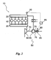
- Fig. 1 shows a turbocharged piston engine 10.
- the engine comprises a plurality of cylinders 15, which are for instance in the case of a four-stroke engine in flow connection, controlled by valves (not shown), with combustion gas and exhaust gas collectors 20, 25.
- the combustion gas i.e. the gas participating in the combustion, is typically air, but in any case gas that contains oxygen.
- the engine comprises a turbocharger arrangement 51 that includes a compressor section 52 and a turbine section 53.
- a second compressor section 55 is coupled in series with the compressor section 52 of the turbocharger arrangement 51, with which second compressor section an electric machine 65 is coupled to a same shaft 70.
- the compressor section 55 and the electric machine 65 are integrated in such a way that the suction conduit 75 of the compressor section is arranged in flow connection with the cooling channels 80 of the electric machine 65 and that the suction air for the compressor section 55 is arranged to pass through the channels 80 of the electric machine 65.
- the gas used in the engine and participating in the combustion typically combustion air
- the compressor section 55 where the pressure of the combustion gas is raised.
- a part of the combustion gases can be led past the electric machine directly to the suction conduit 75 of the compressor section.
- the arrangement comprises preferably a pressure gauge 90 for measuring the pressure produced by the compressor section 55.
- the turbocharger arrangement is preferably run so that the operation of the electric machine 65 is controlled on the basis of pressure measuring in such a way that energy is either brought to the electric machine or energy is taken from the electric machine so as to maintain the pressure produced by the turbocharger arrangement within the range of predetermined minimum and maximum pressures.
- FIG 2 shows a turbocharged piston engine 10, which corresponds to the engine shown in Figure 1 with the exception that its supercharger arrangement is realised in a different way.
- the engine comprises a turbocharger arrangement 50 including a compressor section 55, a turbine section 60 and an electric machine 65, all coupled to a same shaft 70.
- the shaft may be built-up in pieces or it may consist of one piece.
- exhaust gas flows from the cylinders through an exhaust gas collector to the turbine section 60 of the turbocharger arrangement 50, in which the exhaust gas perform work. This work is utilised, according to the invention, by the compressor section 55 and/or by the electric machine 65.
- the compressor section 55 and the electric machine 65 are also integrated in such a way that the suction conduit 75 of the compressor section is arranged in flow connection with the cooling channels 80 of the electric machine 65 and that the suction air of the compressor section 55 is arranged to pass through the channels 80 of the electric machine 65.
- the gas participating in the combustion of the engine typically combustion air
- the compressor section 55 where the pressure of the combustion gas is raised.
- the supercharger arrangement 50 By the supercharger arrangement 50 according to the invention, one embodiment of which is shown in Figure 2 , significant advantages are achieved in various operational situations of the engine 10.
- the electric machine runs both as a generator and a motor, depending on the power balance of the turbocharger arrangement. In such running situations, where the amount of exhaust gases is rather small, the electric machine 65 may be used so as to perform work for the compressor section 55 and thus maintain a higher boost pressure than it would be possible in this situation by the power received from the turbine section. Then, the electric machine acts as an electric motor assisting the rotation of the compressor section.
- the electric machine 65 may be used for retarding the turbine (and simultaneously also the compressor, since these are located on the same shaft) and at the same time for producing electric energy. In this case, the electric machine acts as a generator. This makes it possible that all the exhaust gases of the engine, i.e. the entire exhaust gas flow, can always be led through the turbine section 60, and accordingly, the arrangement does not require a wastegate or other equipment, such as adjustable inlet vanes, for restricting the power of the turbine.
- the arrangement according to the invention enables the dimensioning of the turbine section very efficiently without any risk that the boost pressure or the rotary speed of the supercharger arrangement would rise excessively, as the rotary speed of the assembly can be regulated by adjusting the retardation effect of the electric machine.
- the arrangement also comprises a control unit 85, which may be either a unit dedicated to the turbocharger arrangement or a part of a centralised control system of the engine.
- the control unit is arranged to control at least the operation of the electric machine 65.
- Invention relates according an embodiment of the invention also to a method of running a turbocharged engine with high loads (more than 60 % of maximum capacity) in a turbocharger arrangement 50, which includes a compressor section 55, a turbine section 60 and an electric machine 65 coupled to a same shaft 70, in which method substantially the whole exhaust gas flow of the engine is led to the turbine section of the turbocharger arrangement, where the energy in the exhaust gas is converted to mechanical work, which is utilised for running the compressor section of the turbocharger arrangement and for producing electricity by the electric machine. Further in the method, the combustion air of the engine is heated by transferring heat from the electric machine 65 to the combustion air before the combustion air is conveyed to the compressor section 55.
- the turbocharger arrangement comprises also a measuring device 127 for measuring the rotational speed of the shaft.
- the turbocharger arrangement is preferably run so that the operation of the electric machine is controlled on the basis of the measurement of rotational speed in such a way that that energy is either brought to the electric machine or energy is taken from the electric machine so as to maintain the rotational speed of the turbocharger arrangement within the range of predetermined minimum and maximum rotational speeds.
- the turbocharger arrangement comprises also a pressure gauge 90 for the pressure produced by the compressor section 55.
- the turbocharger arrangement is preferably run so that the operation of the electric machine 65 is controlled on the basis of pressure measuring in such a way that energy is either brought to the electric machine or energy is taken from the electric machine so as to maintain the pressure produced by the turbocharger arrangement within the range of predetermined minimum and maximum pressures.
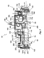
- Fig. 3 shows in more detail an embodiment of the turbocharger arrangement 50 according to the invention, which can be connected in conjunction with a combustion engine by using the principle shown in Figure 2 .
- the turbocharger arrangement operates very flexibly according to the need determined by the operating conditions of the engine, which makes it advantageous e.g. to need to oversize the turbocharger for lower rotational speed ranges of the engine, which was earlier considered a problem.
- the turbocharger arrangement 50 shown in Figure 3 comprises a body 100, which includes a body part 165 of the electric machine, a body part 155 of the compressor section and a body part 160 of the turbine section, all connected to each other, and in which the body part 155 of the compressor section is adapted between the respective body parts of the electric machine and the turbine section.
- the turbine section is here an axial turbine and it comprises a turbine wheel 135 and a set of inlet vanes 131 preceding it in the flow direction of gas.
- a diffuser 132 On the trailing side of the turbine section in the embodiment according to Figure 3 , there is arranged a diffuser 132, to the flange of which the flue gas channel of the engine can be attached.
- the flow of gas in the turbine section is illustrated by arrows.
- the compressor section comprises a radial compressor of two stages, i.e. a first stage 56 and a second stage 57, connected to one another so that there is a flow channel 140 arranged from the pressure side of the first stage to the suction side of the second stage.
- the flow channel 140 is provided with an intercooler 145, by means of which the combustion air flowing from the first stage to the second stage can be cooled before it is fed to the second stage 57.
- Both compressor stages comprise a compressor impeller 170, 175, respectively, adapted on a common shaft 70 and inside compressor enclosures 180, 185 of the first and second stage, respectively, arranged in the body.
- the flow of gas in the compressor section is illustrated by arrows.
- the electric machine 65 of the turbocharger arrangement 50 comprises a permanent magnet rotor 190 arranged in conjunction with the shaft 70 and a stator part 200 surrounding it.
- the stator part is supported on the body part 165 of the electric machine and it comprises an electric connection 202 for transferring electric energy to the electric machine or from the electric machine to the network.
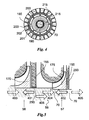
- the stator part 200 comprises gas flow channels 215 extending from the first end 205 to the second end 210 in its axial direction, which channels also act as coolant channels for the electric machine.
- the first gas flow channels 215 of the stator part are arranged radially outside the coil section 201 of the stator part to form an essentially annular flow channel, whereby the coil section 201 of the stator part 200 of the electric machine is arranged radially inside the stator part and/or the flow channels 215 of its body part.
- the stator part is supported on the outer section 202 of the stator part by means of radially extending support parts 203.
- An air gap 216 arranged between the stator and the rotor acts as a second gas flow channel.
- the flow channels form at the same time both coolant channels for the electric machine 65 and suction channels for the compressor section.
- the suction air of the compressor section is arranged to pass through the gas flow channels 215, 216 of the electric machine. In this way, the amount of the gas flow, which in practise consists of the combustion air of the engine, is always sufficient for cooling the electric machine and on the other hand, in a correct temperature for the cooling.
- the gas flow channels 215 of the stator part and/or its body part in the electric machine 65 are dimensioned in regard to the air gap between the rotor and stator part of the electric machine so that an exactly sufficient amount of air for the cooling passes through said air gap, whereby the pressure loss in the cooling can be minimised.
- the cross-sectional flow area of the gas flow channels 215 of the stator part and/or its body part arranged in the stator part 200 is over 90 % of the total cross-sectional area of the flow channels of the electric machine 65, and the cross-sectional flow area of the air gap 216 between the stator part 200 and the rotor 190 is less than 10 % of the total cross-sectional area of the flow channels of the electric machine 65. Thus, less than 10 % of the total gas flow is arranged to flow through the air gap 216 between the stator part 200 and the rotor 190.
- the cross-section of the gas flow channels of the stator part is determined on the basis of this.
- the shaft 70 of the turbocharger arrangement is rotatably supported on the body by means of bearings 125 arranged at the first end of the shaft and bearings 130 arranged at the second end thereof.
- the shaft 70 may be an essentially rigid shaft built-up in pieces, or it may be made of a one-piece shaft.
- the bearings 125 at the first end are supported on the body part 165 of the electric machine 65 and the bearings 130 at the second end on the body part 160 of the turbine section.
- the body part 165 of the electric machine comprises openings 220 arranged in the shell of the body part or at the end thereof for enabling the flow of the suction air of the compressor section to the side of the first end 205 of the stator part of the electric machine.
- the bearings at the first end comprise both a radial bearing system 125.1 and an axial bearing system 125.2.
- An inlet and outlet 225 for lubrication oil is arranged for these systems.
- the housing construction of the bearings at the first end is restricted by the gas flow space facing the first end 205 of the stator part, whereby the suction air of the compressor section also acts as a medium for cooling the housing construction of the bearings at the first end.
- the radial bearing system is preferably a slide bearing system.
- the bearings 130 at the second end (referring to the end facing the turbine section) of the shaft 70 comprise in this embodiment only a radial bearing system.
- the bearings 130 at the second end comprise a bearing housing, which is adapted in this embodiment in the body part 160 of the turbine section 60, but the position of the bearings at the second end of the shaft may in some applications be also inside the turbine section 60, whereby the impact of the exhaust gases on the temperature of the bearing is smaller than in the situation shown in the figure.
- An inlet and outlet 230 for lubrication oil is arranged for the bearings in conjunction with the body part.
- the temperature of the turbine section is relatively high due to the hot exhaust gases flowing therethrough, whereby cooling is arranged in conjunction with the bearings at the second end of the shaft.
- the cooling arrangement comprises at least one axial channel 242, which extends from the end of the shaft 70 past the bearings at the second end, and at one end of which channel there is at least one radial channel 240 extending from the surface of the shaft 70 to the axial channel 242.
- the axial channel 242 extends preferably to the suction side of the second turbine stage 57, to a point after the intercooler 145 in the gas flow.
- the radial channels 240 are arranged on the shaft 70 in the area between the compressor impellers 170, 175 of the first 56 and second 57 compressor stage, respectively.
- gas (air) already at raised pressure and cooled by the intercooler flows along the channels 240, 242 past the bearings 130 at the second end of the shaft, inside the shaft, keeping the temperature of the bearing suitably low. From the channel 242 the gas is discharged into the diffuser of the turbine section and from there, into the exhaust gas channel through the clearances of the turbine wheel 135.
- the channels 240, 242 can be utilised also in conjunction with the detachment of the turbine wheel and the compressor impeller of the second compressor stage by leading fluid at low temperature into the shaft 70 through the channel in order to lower the temperature of the shaft and to reduce its diameter, while the shrink fit between the shaft and the turbine wheel or the compressor impeller of the second compressor stage is disassembled by heating said turbine wheel or compressor impeller.
- sealings 250 are arranged in a certain way behind the compressor impellers, i.e. in a radial compressor on the opposite side of the impeller with respect to the blades.
- the sealings consist of labyrinth seals.
- the arrows 401, 402 with unbroken lines illustrate the forces pushing the thrust bearing and the arrows 403, 404, 405 with dashed lines the forces pulling the thrust bearing.
- the forces 401, 402, 403 and 404 are generated by the compressor section and the force 405 by the turbine section.
- the arrow 406 with a dash-dotted line illustrates the load imposed on the thrust bearing in a normal operational situation.
- the total force impact of the compressor stages is according to and embodiment of the invention adjusted so that it corresponds with a precision of +/-10 % the axial force 405 exerted on the shaft 70 by the turbine section 60, whereby in a normal operational situation the load imposed on the thrust bearing is about +/-10 % of the axial force exerted on the shaft by the turbine. Accordingly, the axial forces in normal situations are relatively small, which results in the load on the thrust bearing being relatively small as well, and thereby its lifetime being long. Almost a balance situation of this kind is achieved so that the sealing 250 of the second compressor stage is arranged between the shaft 70 and the body part 155 and between the second compressor impeller 175 and the body part 155. This provides behind the compressor impellers such surface areas with respect to the pressures and/or forces prevailing there and exerted on other components of the turbocharger arrangement that said force balance can be achieved.
Claims (15)
- Turboladeranordnung (50) für einen Kolbenmotor, umfassend einen Kompressorabschnitt (55) und eine elektrische Maschine (65), gekoppelt auf derselben Welle (70), wobei die elektrische Maschine mit wenigstens einem Gasströmungskanal (215, 216) vorgesehen ist und der Saugkanal für den Kompressorabschnitt in Strömungsverbindung mit dem Gasströmungskanal (215, 216) der elektrischen Maschine (65) angeordnet ist, wobei ein Statorteil (200) und/oder ein Körperteil der elektrischen Maschine (65) mit Gasströmungskanalen (215) vorgesehen ist, so dass Ansaugluft für den Kompressorabschnitt so angeordnet ist, um durch den wenigstens einen Gasströmungskanal der elektrischen Maschine hindurchzugehen, um Kühlung der elektrischen Maschine (65) bereitzustellen, dadurch gekennzeichnet, dass ein Luftspalt (216) zwischen dem Rotor- und dem Statorteil der elektrischen Maschine angeordnet ist, um als Gasströmungskanal der elektrischen Maschine (65) zusätzlich zu dem Gasströmungskanal (215) im Statorteil (200) und/oder einem Körperteil zu dienen.
- Turboladeranordnung nach Anspruch 1, dadurch gekennzeichnet, dass der Hauptteil der Ansaugluft des Kompressorabschnitts (55) angeordnet ist, um durch den wenigstens einen Gasströmungskanal (215, 216) der elektrischen Maschine hindurchzugehen.
- Turboladeranordnung nach Anspruch 1, dadurch gekennzeichnet, dass der Kompressorabschnitt (55) wenigstens eine erste (56) und eine zweite (57) Kompressorstufe umfasst und dass der Ansaugkanal der ersten Kompressorstufe (56) des Kompressorabschnitts in Strömungsverbindung mit dem Gasströmungskanal (215, 216) der elektrischen Maschine angeordnet ist, so dass Ansaugluft für die erste Kompressorstufe des Kompressorabschnitts angeordnet ist, um durch den Gasströmungskanal der elektrischen Maschine (65) hindurchzugehen.
- Turboladeranordnung nach Anspruch 3, dadurch gekennzeichnet, dass im Wesentlichen das gesamte Gas, welches durch die erste Kompressorstufe (56) hindurchgeht, geführt wird, um über die zweite Kompressorstufe (57) zu strömen.
- Turboladeranordnung nach Anspruch 1, dadurch gekennzeichnet, dass die Gasströmungskanäle (215) des Statorteils und/oder des Körperteils der elektrischen Maschine (65) in Bezug auf den Luftspalt (216) zwischen dem Rotor- und dem Statorteil der elektrischen Maschine dimensioniert sind, so dass eine genau ausreichende Menge an Luft zum Kühlen durch den Luftspalt hindurchgeht, wobei der Druckverlust in der Kühlung minimiert werden kann.
- Turboladeranordnung nach Anspruch 1, dadurch gekennzeichnet, dass der Spulenabschnitt (201) des Statorteils (200) der elektrischen Maschine radial innerhalb der Gasströmungskanäle (215) des Statorteils und/oder ihres Körperteils angeordnet ist
- Turboladeranordnung nach Anspruch 1, dadurch gekennzeichnet, dass die Querschnittsströmungsfläche der Gasströmungskanäle (215) des Statorteils und/oder ihres Körperteils, welcher im Statorteil (200) angeordnet ist, über 90% der Gesamtquerschnittsströmungsfläche der Gasströmungskanäle der elektrischen Maschine (65) beträgt.
- Turboladeranordnung nach Anspruch 1, dadurch gekennzeichnet, dass der Querschnitt der Gasströmungskanäle des Statorteils 95-98% der Gesamtquerschnittsströmungsfläche der Gasströmungskanäle der elektrischen Maschine (65) beträgt.
- Turboladeranordnung nach Anspruch 1, dadurch gekennzeichnet, dass die Welle (70) wenigstens einen axialen Strömungskanal (242) umfasst, welcher sich vom Kompressorabschnitt zum zweiten Lager der Welle (70) erstreckt, um Gas, welches durch den Kompressorteil mit Druck beaufschlagt wurde, zu einem Lager (130) zu befördern, um es zu kühlen.
- Turboladeranordnung nach Anspruch 9, dadurch gekennzeichnet, dass die Turboladeranordnung eine Turboladeranordnung ist, welche einen Turbinenabschnitt (60) umfasst, und dadurch gekennzeichnet, dass die Lager (130) am zweiten Ende sich am Wellenende dem Turbinenabschnitt (60) zugewandt befinden.
- Turboladeranordnung nach Anspruch 9, dadurch gekennzeichnet, dass der Kompressorabschnitt zwei Stufen aufweist, und dadurch gekennzeichnet, dass die Strömungskanäle (240, 242) sich von der Ansaugseite der zweiten Kompressorstufe (57) des Kompressorabschnitts (55) zu den Lagern am zweiten Ende der Welle (70) erstrecken.
- Turboladeranordnung nach Anspruch 9, dadurch gekennzeichnet, dass die radialen Lager (125.1, 130) der Welle (70) am ersten Ende durch den Körperteil (165) der elektrischen Maschine (65) und am zweiten Ende durch den Körperteil (160) des Turbinenabschnitts (60) getragen werden.
- Turboladeranordnung nach Anspruch 10, dadurch gekennzeichnet, dass die axialen Lager (125.2) durch den Körperteil (165) der elektrischen Maschine getragen werden.
- Turboladeranordnung nach Anspruch 10, dadurch gekennzeichnet, dass die axialen Lager (125.2) im Turbinenabschnitt angeordnet sind und durch den Körperteil der Turbine getragen werden.
- Turboladeranordnung nach jedem beliebigen der vorangehenden Ansprüche, dadurch gekennzeichnet, dass die Turboladeranordnung eine Turboladeranordnung ist, welche einen Turbinenabschnitt (60) umfasst und dass der Kompressorabschnitt (55), der Turbinenabschnitt (60) und die elektrische Maschine (65) auf der Welle (70) angeordnet sind, so dass der Kompressorabschnitt axial zwischen der elektrischen Maschine und dem Turbinenabschnitt angepasst ist.
Applications Claiming Priority (2)
| Application Number | Priority Date | Filing Date | Title |
|---|---|---|---|
| FI20085016A FI121800B (fi) | 2008-01-10 | 2008-01-10 | Mäntämoottorin ahdinjärjestely |
| PCT/FI2009/050009 WO2009087274A2 (en) | 2008-01-10 | 2009-01-07 | Supercharger arrangement for a piston engine |
Publications (2)
| Publication Number | Publication Date |
|---|---|
| EP2247838A2 EP2247838A2 (de) | 2010-11-10 |
| EP2247838B1 true EP2247838B1 (de) | 2015-03-04 |
Family
ID=39004316
Family Applications (1)
| Application Number | Title | Priority Date | Filing Date |
|---|---|---|---|
| EP09700181.2A Active EP2247838B1 (de) | 2008-01-10 | 2009-01-07 | Aufladeanordnung für einen kolbenmotor |
Country Status (6)
| Country | Link |
|---|---|
| EP (1) | EP2247838B1 (de) |
| JP (1) | JP5259734B2 (de) |
| KR (1) | KR101510917B1 (de) |
| CN (1) | CN101910581A (de) |
| FI (1) | FI121800B (de) |
| WO (1) | WO2009087274A2 (de) |
Families Citing this family (21)
| Publication number | Priority date | Publication date | Assignee | Title |
|---|---|---|---|---|
| DE102010007601A1 (de) | 2010-02-11 | 2011-08-11 | MTU Friedrichshafen GmbH, 88045 | Aufgeladene Brennkraftmaschine |
| JP5433643B2 (ja) * | 2011-07-15 | 2014-03-05 | 三菱重工業株式会社 | 電動過給装置及び多段過給システム |
| GB2493915A (en) * | 2011-08-19 | 2013-02-27 | Bamford Excavators Ltd | Internal combustion engine with turbocharger, supercharger and supercharger bypass |
| US9074524B2 (en) * | 2011-12-09 | 2015-07-07 | Eaton Corporation | Air supply system with two-stage roots blower |
| JP5726095B2 (ja) * | 2012-01-12 | 2015-05-27 | 三菱重工業株式会社 | ハイブリッド排気タービン過給機 |
| JP5894203B2 (ja) | 2014-03-04 | 2016-03-23 | 三菱重工業株式会社 | 過給機の製造方法 |
| JP6563321B2 (ja) * | 2015-12-03 | 2019-08-21 | 三菱重工業株式会社 | 電動機支持機構、圧縮機、および過給機 |
| KR20180127423A (ko) * | 2016-04-07 | 2018-11-28 | 보르그워너 인코퍼레이티드 | 로터 냉각을 이용한 전기 충전 장치 |
| WO2017199695A1 (ja) * | 2016-05-20 | 2017-11-23 | 株式会社Ihi | 過給機の軸受構造および過給機 |
| FR3053544B1 (fr) * | 2016-06-30 | 2023-01-06 | Valeo Systemes De Controle Moteur | Machine electrique avec circuit de refroidissement |
| FR3055368B1 (fr) * | 2016-08-24 | 2018-08-24 | Peugeot Citroen Automobiles Sa | Dispositif de refroidissement de systeme de suralimentation d’air de moteur thermique, et systeme de suralimentation d’air equipe d'un tel dispositif |
| GB2563614B (en) | 2017-06-20 | 2020-06-17 | Dyson Technology Ltd | Brushless motor |
| GB2563624B (en) * | 2017-06-20 | 2020-04-08 | Dyson Technology Ltd | A compressor |
| FR3073579B1 (fr) * | 2017-11-10 | 2021-08-06 | Psa Automobiles Sa | Compresseur electrique comportant un systeme de refroidissement par air integre |
| DE102017220880B4 (de) | 2017-11-22 | 2023-03-09 | Efficient Energy Gmbh | Elektromotor, Wärmepumpe mit dem Elektromotor, Verfahren zum Herstellen des Elektromotors und Verfahren zum Betreiben des Elektromotors unter Verwendung einer Labyrinth-Dichtung |
| CN109441622B (zh) * | 2018-10-29 | 2020-10-27 | 北京航空航天大学 | 一种采用独立润滑冷却系统的双电机辅助涡轮增压器 |
| US11384942B2 (en) | 2018-12-10 | 2022-07-12 | Lg Electronics Inc. | Cogeneration system |
| KR102150858B1 (ko) * | 2019-01-30 | 2020-09-02 | 주식회사 인지니어스 | 자기 커플링을 적용한 전기식 터보 컴파운딩 시스템 |
| GB2586844B (en) | 2019-09-05 | 2021-11-24 | Dyson Technology Ltd | A compressor |
| CN110608176A (zh) * | 2019-10-09 | 2019-12-24 | 合肥工业大学 | 一种电动两级增压器 |
| CN111536057A (zh) * | 2020-05-09 | 2020-08-14 | 太原科技大学 | 一种氢燃料涡轮增程器两级压气机 |
Family Cites Families (10)
| Publication number | Priority date | Publication date | Assignee | Title |
|---|---|---|---|---|
| JPS61201827A (ja) * | 1985-03-05 | 1986-09-06 | Terumi Tokoro | 内燃機関の過給装置 |
| US5605045A (en) * | 1995-09-18 | 1997-02-25 | Turbodyne Systems, Inc. | Turbocharging system with integral assisting electric motor and cooling system therefor |
| US5904471A (en) * | 1996-12-20 | 1999-05-18 | Turbodyne Systems, Inc. | Cooling means for a motor-driven centrifugal air compressor |
| US6305169B1 (en) * | 1999-02-22 | 2001-10-23 | Ralph P. Mallof | Motor assisted turbocharger |
| EP1069313B1 (de) * | 1999-07-16 | 2005-09-14 | Man Turbo Ag | Turboverdichter |
| DE10040122A1 (de) * | 2000-08-17 | 2002-02-28 | Daimler Chrysler Ag | Abgasturbolader für eine Brennkraftmaschine |
| DE10216447C1 (de) * | 2002-04-12 | 2003-09-18 | Forschungszentrum Juelich Gmbh | Abgasturbolader |
| SE525219C2 (sv) | 2003-05-15 | 2004-12-28 | Volvo Lastvagnar Ab | Turboladdarsystem för en förbränningsmotor där båda kompressorstegen är av radialtyp med kompressorhjul försedda med bakåtsvepta blad |
| JP4247217B2 (ja) | 2005-08-25 | 2009-04-02 | 三菱重工業株式会社 | 排気タービン過給機 |
| JP2007120383A (ja) | 2005-10-27 | 2007-05-17 | Toyota Motor Corp | ターボチャージャ |
-
2008
- 2008-01-10 FI FI20085016A patent/FI121800B/fi not_active IP Right Cessation
-
2009
- 2009-01-07 JP JP2010541808A patent/JP5259734B2/ja active Active
- 2009-01-07 EP EP09700181.2A patent/EP2247838B1/de active Active
- 2009-01-07 WO PCT/FI2009/050009 patent/WO2009087274A2/en active Application Filing
- 2009-01-07 CN CN2009801019816A patent/CN101910581A/zh active Pending
- 2009-01-07 KR KR1020107016910A patent/KR101510917B1/ko active IP Right Grant
Also Published As
| Publication number | Publication date |
|---|---|
| JP2011509375A (ja) | 2011-03-24 |
| FI121800B (fi) | 2011-04-15 |
| EP2247838A2 (de) | 2010-11-10 |
| FI20085016A (fi) | 2009-07-11 |
| KR101510917B1 (ko) | 2015-04-17 |
| WO2009087274A2 (en) | 2009-07-16 |
| JP5259734B2 (ja) | 2013-08-07 |
| WO2009087274A3 (en) | 2010-03-25 |
| KR20100117063A (ko) | 2010-11-02 |
| CN101910581A (zh) | 2010-12-08 |
| FI20085016A0 (fi) | 2008-01-10 |
Similar Documents
| Publication | Publication Date | Title |
|---|---|---|
| EP2247838B1 (de) | Aufladeanordnung für einen kolbenmotor | |
| EP2229515B1 (de) | Turboladeranordnung für einen kolbenmotor | |
| US6735945B1 (en) | Electric turbocharging system | |
| US8157544B2 (en) | Motor driven supercharger with motor/generator cooling efficacy | |
| US7571607B2 (en) | Two-shaft turbocharger | |
| US6449950B1 (en) | Rotor and bearing system for electrically assisted turbocharger | |
| JP4875654B2 (ja) | 過給装置 | |
| EP1749991A2 (de) | Lader mit Elektromotor | |
| US9835172B2 (en) | Supplemental air cooling system and air pressure oil sealing system for electrical turbocompound machine | |
| JP2014520992A (ja) | ドライブトレイン、特に車両ドライブトレイン | |
| JP2009257097A (ja) | 排気エネルギー回収装置 | |
| EP4053388A1 (de) | Turboladeranordnung und verfahren zum steuern des betriebs einer turboladeranordnung | |
| GB2564689A (en) | Turbine mounted pump for EGR | |
| JP2008208734A (ja) | 2段圧縮式排気タービン過給機 | |
| EP3810901B1 (de) | Turbolader und verfahren zum betrieb eines turboladers | |
| GB2498760A (en) | Turbine shaft with worm gear |
Legal Events
| Date | Code | Title | Description |
|---|---|---|---|
| PUAI | Public reference made under article 153(3) epc to a published international application that has entered the european phase |
Free format text: ORIGINAL CODE: 0009012 |
|
| 17P | Request for examination filed |
Effective date: 20100802 |
|
| AK | Designated contracting states |
Kind code of ref document: A2 Designated state(s): AT BE BG CH CY CZ DE DK EE ES FI FR GB GR HR HU IE IS IT LI LT LU LV MC MK MT NL NO PL PT RO SE SI SK TR |
|
| DAX | Request for extension of the european patent (deleted) | ||
| RIC1 | Information provided on ipc code assigned before grant |
Ipc: F02B 39/16 20060101ALI20140611BHEP Ipc: F02B 39/00 20060101ALI20140611BHEP Ipc: F02C 6/12 20060101ALI20140611BHEP Ipc: F02B 33/40 20060101ALI20140611BHEP Ipc: F01D 15/10 20060101ALI20140611BHEP Ipc: F02B 37/04 20060101ALI20140611BHEP Ipc: F02B 39/10 20060101ALI20140611BHEP Ipc: F02B 37/013 20060101ALI20140611BHEP Ipc: F02B 37/10 20060101AFI20140611BHEP |
|
| GRAP | Despatch of communication of intention to grant a patent |
Free format text: ORIGINAL CODE: EPIDOSNIGR1 |
|
| INTG | Intention to grant announced |
Effective date: 20140922 |
|
| GRAS | Grant fee paid |
Free format text: ORIGINAL CODE: EPIDOSNIGR3 |
|
| GRAA | (expected) grant |
Free format text: ORIGINAL CODE: 0009210 |
|
| AK | Designated contracting states |
Kind code of ref document: B1 Designated state(s): AT BE BG CH CY CZ DE DK EE ES FI FR GB GR HR HU IE IS IT LI LT LU LV MC MK MT NL NO PL PT RO SE SI SK TR |
|
| REG | Reference to a national code |
Ref country code: GB Ref legal event code: FG4D |
|
| REG | Reference to a national code |
Ref country code: CH Ref legal event code: EP |
|
| REG | Reference to a national code |
Ref country code: IE Ref legal event code: FG4D |
|
| REG | Reference to a national code |
Ref country code: AT Ref legal event code: REF Ref document number: 714106 Country of ref document: AT Kind code of ref document: T Effective date: 20150415 |
|
| REG | Reference to a national code |
Ref country code: DE Ref legal event code: R096 Ref document number: 602009029761 Country of ref document: DE Effective date: 20150416 |
|
| REG | Reference to a national code |
Ref country code: AT Ref legal event code: MK05 Ref document number: 714106 Country of ref document: AT Kind code of ref document: T Effective date: 20150304 Ref country code: NL Ref legal event code: VDEP Effective date: 20150304 |
|
| PG25 | Lapsed in a contracting state [announced via postgrant information from national office to epo] |
Ref country code: HR Free format text: LAPSE BECAUSE OF FAILURE TO SUBMIT A TRANSLATION OF THE DESCRIPTION OR TO PAY THE FEE WITHIN THE PRESCRIBED TIME-LIMIT Effective date: 20150304 Ref country code: NO Free format text: LAPSE BECAUSE OF FAILURE TO SUBMIT A TRANSLATION OF THE DESCRIPTION OR TO PAY THE FEE WITHIN THE PRESCRIBED TIME-LIMIT Effective date: 20150604 Ref country code: SE Free format text: LAPSE BECAUSE OF FAILURE TO SUBMIT A TRANSLATION OF THE DESCRIPTION OR TO PAY THE FEE WITHIN THE PRESCRIBED TIME-LIMIT Effective date: 20150304 Ref country code: ES Free format text: LAPSE BECAUSE OF FAILURE TO SUBMIT A TRANSLATION OF THE DESCRIPTION OR TO PAY THE FEE WITHIN THE PRESCRIBED TIME-LIMIT Effective date: 20150304 Ref country code: FI Free format text: LAPSE BECAUSE OF FAILURE TO SUBMIT A TRANSLATION OF THE DESCRIPTION OR TO PAY THE FEE WITHIN THE PRESCRIBED TIME-LIMIT Effective date: 20150304 Ref country code: LT Free format text: LAPSE BECAUSE OF FAILURE TO SUBMIT A TRANSLATION OF THE DESCRIPTION OR TO PAY THE FEE WITHIN THE PRESCRIBED TIME-LIMIT Effective date: 20150304 |
|
| REG | Reference to a national code |
Ref country code: LT Ref legal event code: MG4D |
|
| PG25 | Lapsed in a contracting state [announced via postgrant information from national office to epo] |
Ref country code: GR Free format text: LAPSE BECAUSE OF FAILURE TO SUBMIT A TRANSLATION OF THE DESCRIPTION OR TO PAY THE FEE WITHIN THE PRESCRIBED TIME-LIMIT Effective date: 20150605 Ref country code: AT Free format text: LAPSE BECAUSE OF FAILURE TO SUBMIT A TRANSLATION OF THE DESCRIPTION OR TO PAY THE FEE WITHIN THE PRESCRIBED TIME-LIMIT Effective date: 20150304 Ref country code: LV Free format text: LAPSE BECAUSE OF FAILURE TO SUBMIT A TRANSLATION OF THE DESCRIPTION OR TO PAY THE FEE WITHIN THE PRESCRIBED TIME-LIMIT Effective date: 20150304 |
|
| PG25 | Lapsed in a contracting state [announced via postgrant information from national office to epo] |
Ref country code: NL Free format text: LAPSE BECAUSE OF FAILURE TO SUBMIT A TRANSLATION OF THE DESCRIPTION OR TO PAY THE FEE WITHIN THE PRESCRIBED TIME-LIMIT Effective date: 20150304 |
|
| PG25 | Lapsed in a contracting state [announced via postgrant information from national office to epo] |
Ref country code: CZ Free format text: LAPSE BECAUSE OF FAILURE TO SUBMIT A TRANSLATION OF THE DESCRIPTION OR TO PAY THE FEE WITHIN THE PRESCRIBED TIME-LIMIT Effective date: 20150304 Ref country code: PT Free format text: LAPSE BECAUSE OF FAILURE TO SUBMIT A TRANSLATION OF THE DESCRIPTION OR TO PAY THE FEE WITHIN THE PRESCRIBED TIME-LIMIT Effective date: 20150706 Ref country code: EE Free format text: LAPSE BECAUSE OF FAILURE TO SUBMIT A TRANSLATION OF THE DESCRIPTION OR TO PAY THE FEE WITHIN THE PRESCRIBED TIME-LIMIT Effective date: 20150304 Ref country code: RO Free format text: LAPSE BECAUSE OF FAILURE TO SUBMIT A TRANSLATION OF THE DESCRIPTION OR TO PAY THE FEE WITHIN THE PRESCRIBED TIME-LIMIT Effective date: 20150304 Ref country code: SK Free format text: LAPSE BECAUSE OF FAILURE TO SUBMIT A TRANSLATION OF THE DESCRIPTION OR TO PAY THE FEE WITHIN THE PRESCRIBED TIME-LIMIT Effective date: 20150304 |
|
| PG25 | Lapsed in a contracting state [announced via postgrant information from national office to epo] |
Ref country code: IS Free format text: LAPSE BECAUSE OF FAILURE TO SUBMIT A TRANSLATION OF THE DESCRIPTION OR TO PAY THE FEE WITHIN THE PRESCRIBED TIME-LIMIT Effective date: 20150704 Ref country code: PL Free format text: LAPSE BECAUSE OF FAILURE TO SUBMIT A TRANSLATION OF THE DESCRIPTION OR TO PAY THE FEE WITHIN THE PRESCRIBED TIME-LIMIT Effective date: 20150304 |
|
| REG | Reference to a national code |
Ref country code: DE Ref legal event code: R097 Ref document number: 602009029761 Country of ref document: DE |
|
| PG25 | Lapsed in a contracting state [announced via postgrant information from national office to epo] |
Ref country code: IT Free format text: LAPSE BECAUSE OF FAILURE TO SUBMIT A TRANSLATION OF THE DESCRIPTION OR TO PAY THE FEE WITHIN THE PRESCRIBED TIME-LIMIT Effective date: 20150304 |
|
| PLBE | No opposition filed within time limit |
Free format text: ORIGINAL CODE: 0009261 |
|
| STAA | Information on the status of an ep patent application or granted ep patent |
Free format text: STATUS: NO OPPOSITION FILED WITHIN TIME LIMIT |
|
| PG25 | Lapsed in a contracting state [announced via postgrant information from national office to epo] |
Ref country code: DK Free format text: LAPSE BECAUSE OF FAILURE TO SUBMIT A TRANSLATION OF THE DESCRIPTION OR TO PAY THE FEE WITHIN THE PRESCRIBED TIME-LIMIT Effective date: 20150304 |
|
| 26N | No opposition filed |
Effective date: 20151207 |
|
| PG25 | Lapsed in a contracting state [announced via postgrant information from national office to epo] |
Ref country code: SI Free format text: LAPSE BECAUSE OF FAILURE TO SUBMIT A TRANSLATION OF THE DESCRIPTION OR TO PAY THE FEE WITHIN THE PRESCRIBED TIME-LIMIT Effective date: 20150304 |
|
| PG25 | Lapsed in a contracting state [announced via postgrant information from national office to epo] |
Ref country code: BE Free format text: LAPSE BECAUSE OF NON-PAYMENT OF DUE FEES Effective date: 20160131 |
|
| PG25 | Lapsed in a contracting state [announced via postgrant information from national office to epo] |
Ref country code: BE Free format text: LAPSE BECAUSE OF FAILURE TO SUBMIT A TRANSLATION OF THE DESCRIPTION OR TO PAY THE FEE WITHIN THE PRESCRIBED TIME-LIMIT Effective date: 20150304 Ref country code: LU Free format text: LAPSE BECAUSE OF FAILURE TO SUBMIT A TRANSLATION OF THE DESCRIPTION OR TO PAY THE FEE WITHIN THE PRESCRIBED TIME-LIMIT Effective date: 20160107 |
|
| PG25 | Lapsed in a contracting state [announced via postgrant information from national office to epo] |
Ref country code: MC Free format text: LAPSE BECAUSE OF FAILURE TO SUBMIT A TRANSLATION OF THE DESCRIPTION OR TO PAY THE FEE WITHIN THE PRESCRIBED TIME-LIMIT Effective date: 20150304 |
|
| REG | Reference to a national code |
Ref country code: FR Ref legal event code: ST Effective date: 20160930 |
|
| REG | Reference to a national code |
Ref country code: IE Ref legal event code: MM4A |
|
| PG25 | Lapsed in a contracting state [announced via postgrant information from national office to epo] |
Ref country code: FR Free format text: LAPSE BECAUSE OF NON-PAYMENT OF DUE FEES Effective date: 20160201 |
|
| PG25 | Lapsed in a contracting state [announced via postgrant information from national office to epo] |
Ref country code: IE Free format text: LAPSE BECAUSE OF NON-PAYMENT OF DUE FEES Effective date: 20160107 |
|
| PG25 | Lapsed in a contracting state [announced via postgrant information from national office to epo] |
Ref country code: MT Free format text: LAPSE BECAUSE OF FAILURE TO SUBMIT A TRANSLATION OF THE DESCRIPTION OR TO PAY THE FEE WITHIN THE PRESCRIBED TIME-LIMIT Effective date: 20150304 |
|
| PG25 | Lapsed in a contracting state [announced via postgrant information from national office to epo] |
Ref country code: HU Free format text: LAPSE BECAUSE OF FAILURE TO SUBMIT A TRANSLATION OF THE DESCRIPTION OR TO PAY THE FEE WITHIN THE PRESCRIBED TIME-LIMIT; INVALID AB INITIO Effective date: 20090107 Ref country code: CY Free format text: LAPSE BECAUSE OF FAILURE TO SUBMIT A TRANSLATION OF THE DESCRIPTION OR TO PAY THE FEE WITHIN THE PRESCRIBED TIME-LIMIT Effective date: 20150304 |
|
| PG25 | Lapsed in a contracting state [announced via postgrant information from national office to epo] |
Ref country code: TR Free format text: LAPSE BECAUSE OF FAILURE TO SUBMIT A TRANSLATION OF THE DESCRIPTION OR TO PAY THE FEE WITHIN THE PRESCRIBED TIME-LIMIT Effective date: 20150304 Ref country code: MK Free format text: LAPSE BECAUSE OF FAILURE TO SUBMIT A TRANSLATION OF THE DESCRIPTION OR TO PAY THE FEE WITHIN THE PRESCRIBED TIME-LIMIT Effective date: 20150304 Ref country code: MT Free format text: LAPSE BECAUSE OF FAILURE TO SUBMIT A TRANSLATION OF THE DESCRIPTION OR TO PAY THE FEE WITHIN THE PRESCRIBED TIME-LIMIT Effective date: 20160131 |
|
| PG25 | Lapsed in a contracting state [announced via postgrant information from national office to epo] |
Ref country code: BG Free format text: LAPSE BECAUSE OF FAILURE TO SUBMIT A TRANSLATION OF THE DESCRIPTION OR TO PAY THE FEE WITHIN THE PRESCRIBED TIME-LIMIT Effective date: 20150304 |
|
| PGFP | Annual fee paid to national office [announced via postgrant information from national office to epo] |
Ref country code: CH Payment date: 20230111 Year of fee payment: 15 |
|
| PGFP | Annual fee paid to national office [announced via postgrant information from national office to epo] |
Ref country code: DE Payment date: 20240119 Year of fee payment: 16 Ref country code: GB Payment date: 20240119 Year of fee payment: 16 Ref country code: CH Payment date: 20240202 Year of fee payment: 16 |