EP2247404B1 - Marking machine - Google Patents
Marking machine Download PDFInfo
- Publication number
- EP2247404B1 EP2247404B1 EP09721665A EP09721665A EP2247404B1 EP 2247404 B1 EP2247404 B1 EP 2247404B1 EP 09721665 A EP09721665 A EP 09721665A EP 09721665 A EP09721665 A EP 09721665A EP 2247404 B1 EP2247404 B1 EP 2247404B1
- Authority
- EP
- European Patent Office
- Prior art keywords
- axis
- marking
- marker
- along
- moving
- Prior art date
- Legal status (The legal status is an assumption and is not a legal conclusion. Google has not performed a legal analysis and makes no representation as to the accuracy of the status listed.)
- Active
Links
- 230000000903 blocking effect Effects 0.000 claims description 9
- 238000009527 percussion Methods 0.000 claims description 8
- 230000005294 ferromagnetic effect Effects 0.000 claims description 3
- 239000003550 marker Substances 0.000 claims 27
- 238000006073 displacement reaction Methods 0.000 description 13
- 230000000295 complement effect Effects 0.000 description 1
- PCHJSUWPFVWCPO-UHFFFAOYSA-N gold Chemical compound [Au] PCHJSUWPFVWCPO-UHFFFAOYSA-N 0.000 description 1
- 239000010931 gold Substances 0.000 description 1
- 229910052737 gold Inorganic materials 0.000 description 1
- 238000002347 injection Methods 0.000 description 1
- 239000007924 injection Substances 0.000 description 1
- 239000002184 metal Substances 0.000 description 1
- 229910052751 metal Inorganic materials 0.000 description 1
Images
Classifications
-
- B—PERFORMING OPERATIONS; TRANSPORTING
- B23—MACHINE TOOLS; METAL-WORKING NOT OTHERWISE PROVIDED FOR
- B23Q—DETAILS, COMPONENTS, OR ACCESSORIES FOR MACHINE TOOLS, e.g. ARRANGEMENTS FOR COPYING OR CONTROLLING; MACHINE TOOLS IN GENERAL CHARACTERISED BY THE CONSTRUCTION OF PARTICULAR DETAILS OR COMPONENTS; COMBINATIONS OR ASSOCIATIONS OF METAL-WORKING MACHINES, NOT DIRECTED TO A PARTICULAR RESULT
- B23Q1/00—Members which are comprised in the general build-up of a form of machine, particularly relatively large fixed members
- B23Q1/0009—Energy-transferring means or control lines for movable machine parts; Control panels or boxes; Control parts
-
- B—PERFORMING OPERATIONS; TRANSPORTING
- B23—MACHINE TOOLS; METAL-WORKING NOT OTHERWISE PROVIDED FOR
- B23Q—DETAILS, COMPONENTS, OR ACCESSORIES FOR MACHINE TOOLS, e.g. ARRANGEMENTS FOR COPYING OR CONTROLLING; MACHINE TOOLS IN GENERAL CHARACTERISED BY THE CONSTRUCTION OF PARTICULAR DETAILS OR COMPONENTS; COMBINATIONS OR ASSOCIATIONS OF METAL-WORKING MACHINES, NOT DIRECTED TO A PARTICULAR RESULT
- B23Q1/00—Members which are comprised in the general build-up of a form of machine, particularly relatively large fixed members
- B23Q1/25—Movable or adjustable work or tool supports
- B23Q1/26—Movable or adjustable work or tool supports characterised by constructional features relating to the co-operation of relatively movable members; Means for preventing relative movement of such members
-
- B—PERFORMING OPERATIONS; TRANSPORTING
- B23—MACHINE TOOLS; METAL-WORKING NOT OTHERWISE PROVIDED FOR
- B23Q—DETAILS, COMPONENTS, OR ACCESSORIES FOR MACHINE TOOLS, e.g. ARRANGEMENTS FOR COPYING OR CONTROLLING; MACHINE TOOLS IN GENERAL CHARACTERISED BY THE CONSTRUCTION OF PARTICULAR DETAILS OR COMPONENTS; COMBINATIONS OR ASSOCIATIONS OF METAL-WORKING MACHINES, NOT DIRECTED TO A PARTICULAR RESULT
- B23Q5/00—Driving or feeding mechanisms; Control arrangements therefor
-
- B—PERFORMING OPERATIONS; TRANSPORTING
- B44—DECORATIVE ARTS
- B44B—MACHINES, APPARATUS OR TOOLS FOR ARTISTIC WORK, e.g. FOR SCULPTURING, GUILLOCHING, CARVING, BRANDING, INLAYING
- B44B3/00—Artist's machines or apparatus equipped with tools or work holders moving or able to be controlled substantially two- dimensionally for carving, engraving, or guilloching shallow ornamenting or markings
- B44B3/04—Artist's machines or apparatus equipped with tools or work holders moving or able to be controlled substantially two- dimensionally for carving, engraving, or guilloching shallow ornamenting or markings wherein non-plane surfaces are worked
-
- B—PERFORMING OPERATIONS; TRANSPORTING
- B44—DECORATIVE ARTS
- B44B—MACHINES, APPARATUS OR TOOLS FOR ARTISTIC WORK, e.g. FOR SCULPTURING, GUILLOCHING, CARVING, BRANDING, INLAYING
- B44B3/00—Artist's machines or apparatus equipped with tools or work holders moving or able to be controlled substantially two- dimensionally for carving, engraving, or guilloching shallow ornamenting or markings
- B44B3/06—Accessories, e.g. tool or work holders
- B44B3/063—Tool holders
-
- B—PERFORMING OPERATIONS; TRANSPORTING
- B44—DECORATIVE ARTS
- B44B—MACHINES, APPARATUS OR TOOLS FOR ARTISTIC WORK, e.g. FOR SCULPTURING, GUILLOCHING, CARVING, BRANDING, INLAYING
- B44B3/00—Artist's machines or apparatus equipped with tools or work holders moving or able to be controlled substantially two- dimensionally for carving, engraving, or guilloching shallow ornamenting or markings
- B44B3/06—Accessories, e.g. tool or work holders
- B44B3/065—Work holders
Abstract
Description
La présente invention concerne le domaine technique des dispositifs permettant d'assurer le marquage de la surface d'un objet, par déformation de cette dernière notamment.The present invention relates to the technical field of devices for ensuring the marking of the surface of an object, by deformation of the latter in particular.
Ainsi, dans le domaine ci-dessus, il est connu de réaliser le marquage d'objets métalliques par micro percussions, au moyen d'un système de marquage comprenant une pointe qui est animée d'un mouvement alternatif de translation et qui vient frapper la surface à marquer, pour y former un impact sensiblement ponctuel.Thus, in the above field, it is known to achieve the marking of metal objects by micro percussion, by means of a marking system comprising a tip which is driven by an alternating movement of translation and which hits the surface to be marked, to form a substantially punctual impact.
Il est alors possible, en déplaçant l'organe de marquage dans deux directions croisées, de réaliser, sur la surface à marquer, des signes en deux dimensions.It is then possible, by moving the marking member in two crossed directions, to produce, on the surface to be marked, two-dimensional signs.
Afin d'obtenir ce déplacement croisé de l'organe de marquage, l'organe de marquage est de façon traditionnelle déplacé en translation suivant deux axes X, Y perpendiculaires matérialisés par des rails de guidage ou autre système sur lesquels l'organe de marquage est déplacé dans le plan défini par les axes perpendiculaires par des moyens moteurs commandés automatiquement par des moyens électroniques de commande intégrés généralement dans une console programmable par l'utilisateur.In order to obtain this cross-displacement of the marking member, the marking member is traditionally displaced in translation along two perpendicular X, Y axes represented by guide rails or other systems on which the marking member is moved in the plane defined by the perpendicular axes by motor means automatically controlled by electronic control means generally integrated in a user programmable console.
Ainsi, il est possible, par la combinaison de ces mouvements de translation de déplacer l'organe de marquage dans une fenêtre, dite également de marquage, définie par l'amplitude des mouvements en translation de l'organe de marquage. Les dispositifs fonctionnant sur ce principe permettent alors de réaliser des signes en deux dimensions de bonne qualité.Thus, it is possible, by combining these translational movements to move the marking member in a window, also called marking, defined by the amplitude of the translational movement of the marking member. Devices operating on this principle then make it possible to make two-dimensional signs of good quality.
Afin de marquer des pièces circulaires, il est généralement nécessaire d'utiliser un axe complémentaire de rotation nommé axe D. Cet axe de rotation D est déporté par rapport à l'organe de marquage et il nécessite le mise en oeuvre de moyens moteur de mise en rotation des pièces à graver autour de l'axe D. Ceci implique l'utilisation de moyens électroniques de commande aptes à piloter les trois différents moyens moteurs de déplacement selon chacun des axes X, Y et D. Un exemple d'une telle machine est décrit dans la demande de
Or de tels moyens de commande dits « 3 axes » sont généralement assez complexes ce qui augmente fortement les coûts de production et de vente des machines de marquage de ce type, et limite de ce fait le développement de ce type de machine malgré une importante demande des utilisateurs.Gold such control means called "3-axis" are generally quite complex which greatly increases the costs of production and sales of marking machines of this type, and therefore limits the development of this type of machine despite significant demand users.
Ainsi, il est apparu le besoin de disposer d'un nouveau type de dispositif de marquage qui, tout en conservant le principe de déplacement de l'organe de marquage selon deux axes de translation X, Y par rapport à un troisième axe de rotation D soit d'un coût réduit par rapport aux machines de marquage de ce type connues.Thus, it appeared the need to have a new type of marking device which, while retaining the principle of displacement of the marking member along two translation axes X, Y relative to a third axis of rotation D either at a reduced cost compared with known marking machines of this type.
Afin d'atteindre cet objectif, invention concerne un dispositif de marquage d'une surface comportant:
- des moyens de marquage comportant un organe de marquage apte à réaliser un point ou une marque sensiblement ponctuelle,
- des moyens de déplacement de l'organe de marquage dans une fenêtre de marquage selon deux axes X, Y perpendiculaires entre eux et à la surface à marquer pour réaliser des signes sur la surface à marquer, lesdits moyens de déplacement comportant des moyens moteurs,
- des moyens de support et de déplacement de l'objet à marquer en rotation autour d'un axe D parallèle à un au moins des axes X, Y, lesdits moyens de support et de déplacement de l'objet comportant au moins des moyens moteurs d'entrainement en rotation selon l'axe D;
- des moyens automatiques de commande des moyens de déplacement de l'organe de marquage et de l'objet à marquer selon les axes X, Y, D.
- marking means comprising a marking member adapted to produce a point or a substantially punctuated mark,
- means for moving the marking member in a marking window along two axes X, Y perpendicular to each other and to the surface to be marked in order to make signs on the surface to be marked, said moving means comprising driving means,
- means for supporting and displacing the object to be rotated about an axis D parallel to at least one of the axes X, Y, said means for supporting and moving the object comprising at least driving means rotational drive along the axis D;
- automatic means for controlling the means for moving the marking member and the object to be marked along the X, Y, D axes.
Le dispositif de marquage de l'invention se caractérise par le fait que les moyens automatiques de commande intègrent des moyens électroniques d'alimentation et de pilotage des moyens moteurs de déplacement selon les axes X, Y ainsi que des moyens de dérivation de l'alimentation des moyens moteurs de déplacement selon l'axe Y vers les moyens moteurs de déplacement selon l'axe D de manière à piloter les moyens moteurs de déplacement selon l'axe D par les moyens d'alimentation et de pilotage de l'axe Y.The marking device of the invention is characterized in that the automatic control means incorporate electronic means for supplying and controlling the driving means of movement along the X, Y axes as well as means for shunting the feed. displacement means along the Y axis to the drive means along the axis D so as to drive the drive means along the axis D by the supply and control means of the Y axis.
Selon l'invention, les moyens de dérivation de l'alimentation des moyens moteurs de déplacement selon l'axe Y vers les moyens moteurs de déplacement selon l'axe D comportent des systèmes de relais de commutation.According to the invention, the means for deriving the supply of the displacement motor means along the Y axis to the displacement motor means along the axis D comprise switching relay systems.
Conformément à une caractéristique préférée, le dispositif de l'invention comporte des moyens de blocage des moyens de déplacement de la tête de marquage selon l'axe Y.According to a preferred characteristic, the device of the invention comprises means for blocking the means for moving the marking head along the axis Y.
Toujours selon l'invention et dans une première variante, les moyens de blocage comportent un aimant permanent, ou tout autre système mécanique, apte à bloquer les moyens de déplacement de la tête de marquage perpendiculairement selon l'axe Y pendant l'alimentation des moyens moteurs de déplacement selon l'axe D.Still according to the invention and in a first variant, the locking means comprise a permanent magnet, or any other mechanical system, capable of blocking the means for moving the marking head perpendicularly along the Y axis during the feeding of the means. displacement motors along the D axis.
Toujours selon l'invention et dans une seconde variante, les moyens de blocage consistent en l'injection par les moyens automatiques de commande d'un courant de maintien dans les moyens moteurs de déplacement selon l'axe Y.Still according to the invention and in a second variant, the blocking means consist of the injection by the automatic control means of a holding current in the motor means of displacement along the Y axis.
Toujours selon l'invention, les moyens de déplacement de l'organe de marquage selon les axes X, Y comportent au moins un moyen de guidage en translation de l'organe de marquage selon l'axe X parallèlement et à la surface à marquer et qu'au moins un rail de guidage ou autre en translation de l'organe de marquage selon l'axe Y perpendiculairement à l'axe X.Still according to the invention, the means for moving the marking member along the X, Y axes comprise at least one means for guiding the marking member in translation along the X axis in parallel with the surface to be marked and at least one guide rail or other in translation of the marking member along the Y axis perpendicular to the X axis.
Toujours selon l'invention, les moyens moteurs de déplacement de l'organe de marquage comporte un premier chariot motorisé de déplacement en translation dans les deux sens de l'organe de marquage selon l'axe Y, ainsi qu'un second chariot motorisé de déplacement en translation dans les deux sens de l'organe de marquage selon l'axe X.Still according to the invention, the motor means for moving the marking member comprises a first motorized carriage for translational movement in the two directions of the marking member along the Y axis, and a second motorized carriage of displacement in translation in both directions of the marking member along the axis X.
De façon préférée, les moyens de marquage comprennent un système à micro percussion comprennent l'organe de marquage, muni d'une pointe de marquage mobile entre une position de repos et de marquage.Preferably, the marking means comprise a micro-percussion system comprise the marking member, provided with a marking tip movable between a rest position and marking.
De plus, le système de marquage à micro percussion comprend une bobine électromagnétique, à l'intérieur de laquelle est disposé un noyau ferromagnétique qui agit sur la pointe de marquage et qui est mobile en translation, entre une position de repos et de marquage. En variante, le système de marquage à micro percussion peut également comprendre un système pneumatique qui agit sur la pointe de marquage.In addition, the micro-percussion marking system comprises an electromagnetic coil, inside which is disposed a ferromagnetic core which acts on the marking tip and which is movable in translation, between a rest position and marking. Alternatively, the micro-percussion marking system may also include a pneumatic system which acts on the marking tip.
Diverses autres caractéristiques de l'invention ressortent de la description ci-dessous effectuée en référence aux dessins annexés qui illustrent une forme préférée, non limitative, de réalisation du dispositif de marquage selon l'invention, telle que définie par les revendications annexées.Various other characteristics of the invention will become apparent from the description below made with reference to the accompanying drawings which illustrate a preferred, non-limiting embodiment of the marking device according to the invention, as defined by the appended claims.
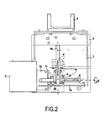
La
La
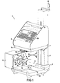
Un dispositif de marquage selon l'invention, tel qu'illustré schématiquement à la
Le système de marquage 4 est réalisé sous la forme d'un système à micro-percussions électromagnétiques ou autre comprenant un organe de marquage 8, dont l'extrémité est destinée à venir impacter la surface S d'un objet O pour y réaliser des déformations en creux ou points d'impacts, comme cela apparaîtra par la suite. L'organe de marquage 8 comprend de préférence une bobine électromagnétique, à l'intérieur de laquelle est disposé un noyau ferromagnétique qui agit sur une pointe de marquage 81 et qui est mobile en translation dans la bobine entre une position de repos et une position de marquage.The marking system 4 is made in the form of an electromagnetic or other micro-percussion system comprising a
L'objet O est placé entre les mors 11 d'un mandrin 10 de support et de mise en rotation dudit objet O autour d'un axe de rotation D, ledit mandrin 10 étant accouplé à un moteur électrique d'entrainement disposé dans un carter C étant solidaire du pied 3 du dispositif 1 par tous moyens appropriés, et notamment dans l'exemple représenté par l'intermédiaire d'une platine 12 fixée sur le pied 3 de manière coulissante par des tenons ou vis 13 insérés dans une rainure en T 14 formée sur le pied 3.The object O is placed between the
Dans la mesure où la pointe de marquage réalise des déformations sensiblement ponctuelles et où il est souhaité, conformément à un objectif de l'invention, réaliser des signes en deux dimensions sur la surface S de l'objet O, le système de marquage 5 comprend, en outre, des moyens de déplacement 15, 16, 17, 18 de l'organe de marquage 8.Insofar as the marking tip produces substantially punctual deformations and where it is desired, in accordance with an objective of the invention, to produce two-dimensional signs on the surface S of the object O , the
Selon l'exemple illustré sur la
Le rail 15, matérialisant l'axe X de translation de l'organe de marquage 8, est parallèle à l'axe D de rotation de l'objet O sur l'étrier. Le rail 16, matérialisant l'axe Y de translation de l'organe de marquage 8 est quant à lui perpendiculaire au rail 15 et à l'axe D.The
Le rail 16 formant l'axe Y est fixé sur la platine 7. Le rail 15 quant à lui est monté mobile sur le rail 16 par l'intermédiaire d'un chariot motorisé 17, comprenant par exemple un moteur électrique pas à pas, permettant la translation du chariot 17 le long du rail 16 selon l'axe Y. De plus, le rail 15 porte lui l'organe de marquage 8, qui est porté sur un second chariot motorisé 18, lui aussi par exemple équipé d'un moteur électrique pas à pas, solidaire du rail 15.The
L'amplitude de déplacement de l'organe de marquage 8 le long des rails de guidage 15, 16 définit une fenêtre de marquage dont la longueur est fixée par l'amplitude de la translation selon l'axe X et dont la largeur est déterminée par l'amplitude de la translation selon l'axe Y. Il est alors possible, lors de la mise en marche du système de marquage 5, de venir impacter avec la pointe 81 de l'organe de marquage tout point de la surface S d'un objet O situé dans la fenêtre de marquage.The amplitude of displacement of the
Les chariots motorisés 17, 18 sont avantageusement alimentés et pilotés par des moyens de commande électronique intégrés à la console de commande 6. Ces moyens de commande comportent des moyens électroniques d'alimentation et de pilotage des chariots motorisés 17, 18 de déplacement de la tête de marquage 8 sur les rails 15, 16 selon les axes X, Y. Ces moyens de commande sont généralement appelés « driver moteur Y » pour le pilotage du chariot motorisé 17 et « driver moteur X » pour le pilotage du chariot 18. Ces « driver moteur » X et Y sont de façon avantageuse implémentés directement sur une carte électronique de pilotage intégrée dans la console de commande et programmable par l'utilisateur au moyen d'un clavier 19 sur cette console 6.The motorized
Les moyens électroniques de commande sont également configurés, conformément à la présente invention, pour alimenter et piloter le moteur d'entraînement en rotation autour de l'axe D du mandrin 10 de support de l'objet O à marquer. Une telle rotation s'avère parfois nécessaire et avantageuse pour marquer des pièces circulaires telles que la pièce O représentée sur la
De façon caractéristique de la présente invention, le pilotage du moteur d'entraînement du mandrin 10 n'est pas assuré par un driver moteur dédié mais par le « driver moteur Y » par dérivation des phases d'alimentation du chariot motorisé 17 vers le moteur d'entraînement du mandrin 10 autour de l'axe D.In a characteristic manner of the present invention, the control of the drive motor of the
Pour ce faire, les moyens électroniques de commande comportent des moyens de dérivation, notamment des relais, de l'alimentation du chariot 17 de déplacement de l'organe 8 sur l'axe 16 le moteur d'entrainement du mandrin 10 selon l'axe D.To do this, the electronic control means comprise bypass means, including relays, the supply of the
Ainsi, l'électronique de commande du dispositif de marquage 3 axes X, Y, D de l'invention n'intègre que deux commandes d'axes de pilotage, c'est-à-dire les driver moteur X et Y, le driver moteur Y servant à piloter le moteur d'entrainement du mandrin 10 sur l'axe D.Thus, the control electronics of the 3-axis marking device X , Y , D of the invention integrates only two commands of control axes, that is to say the X and Y motor drivers, the driver Y motor used to drive the driving motor of the
La carte électronique reste donc sensiblement identique à celle des machines de marquage dites « 2 axes » ce qui permet de réduire considérablement le coût du dispositif de marquage 1 de l'invention par rapport aux autres machines 3 axes connues.The electronic card therefore remains substantially identical to that of the so-called "2-axis" marking machines, which considerably reduces the cost of the marking device 1 of the invention compared with other known 3-axis machines.
Pour garantir le positionnement de la tête de marquage 8 sur une génératrice de l'objet O porté sur le mandrin 10 pendant la rotation dudit objet autour de l'axe D, le chariot motorisé 17 est bloqué en position à une extrémité du rail 15 mécaniquement par un aimant 20, solidaire dudit chariot 17 et qui vient en butée contre le rebord frontal 7a de la platine de support 7 du système de marquage 5. L'aimant 20 est un aimant permanent dimensionné de telle sorte que la force de maintient soit suffisante pour bloquer le chariot 17 en position pendant le marquage de l'objet en rotation sur l'axe D, mais pas trop puissant pour que le couple moteur du chariot motorisé 17 une fois l'alimentation de celui-ci rétablie après désactivation du moteur d'axe D puisse après le marquage dégager l'aimant du rebord frontal de la platine pour ramener le chariot 17 et l'organe de marquage 8 vers une position d'origine.To guarantee the positioning of the marking
Bien entendu, tout autre système mécanique de blocage de l'organe 8 sur le rail 15 peut être également envisagé sans sortir du cadre de l'invention. Il est également possible de bloquer cette position de l'organe 8 en injectant un courant de maintient dans le moteur pas à pas du chariot motorisé 17.Of course, any other mechanical locking system of the
Le dispositif de marquage de l'invention, et notamment les moyens de commande du système de marquage, sont ainsi constitués qu'à tout moment d'un cycle de marquage de la surface S d'un objet O, l'alimentation du chariot motorisé de déplacement de l'organe de marquage 8 selon l'axe Y peut être basculé vers le moteur d'entraînement du mandrin 10 sur l'axe D et inversement, permettant d'avoir des fonctionnalités similaires à une machine 3 axes et de marquer des pièces circulaires sans difficultés avec un dispositif de marquage 1 d'un coût réduit.The marking device of the invention, and in particular the control means of the marking system, are thus constituted that at any time of a marking cycle of the surface S of an object O , the power supply of the motorized trolley of displacement of the marking
La commutation d'alimentation et de pilotage par commande électronique entre le chariot motorisé 17 de déplacement de l'organe de marquage 8 selon l'axe Y et le moteur de pilotage du mandrin 10 selon l'axe D permet de se déplacer sur 3 axes dans un même cycle de marquage, pour marquer dans des gorges par exemple, et de faire revenir automatiquement l'organe de marquage 8 en position d'origine en fin de cycle dégageant ainsi l'accès à l'objet O une fois marqué pour l'opérateur.Power switching and control by electronic control between the
Claims (10)
- A device (1) for marking a surface (S) of an object (0), the device comprising:• a support frame (2);• marker means (5) including a marker member (8) suitable for marking a point or a substantially point-sized mark;• movement means (15, 16, 17, 18) for moving the marker member (8) in a marking window along two axes (X, Y) that are mutually perpendicular and perpendicular to the surface (S) for marking in order to make signs on the surface for marking, said movement means including motor means (17, 18);• means (10) for supporting and moving the object (O) for marking in rotation about an axis (D) parallel to at least one of the axes (X, Y), said means (10) for supporting and moving the object (O) including at least motor means for driving in rotation about the axis (D); and• automatic control means (6) for controlling the means for moving the marker member (8) and the object (O) for marking relative to the axes (X, Y, D);the device being characterized in that the automatic control means (6) incorporate electronic means for powering and controlling motor means (17, 18) for movement along the axis (X, Y) and means for diverting the power supply for the motor means for movement along the axis (Y) to motor means for movement about the axis (D) so as to control the motor means for movement about the axis (D) by the means for powering and controlling relative to the axis (Y).
- A marker device according to claim 1, characterized in that the means for diverting the power supply from the motor means for movement along the axis (Y) to the motor means for movement about the axis (D) comprise electronic switch relay systems.
- A marker device according to claim 1 or claim 2, characterized in that it includes blocking means for blocking the means for moving the marker head along the axis (Y).
- A marker device according to claim 3, characterized in that the blocking means comprise a permanent magnet (20) suitable for blocking the means for moving the marker member (8) perpendicularly along the axis (Y) while powering the motor means for movement about the axis (D).
- A marker device according to claim 3, characterized in that the blocking means consist in the automatic control means injecting a holding current into the motor means for movement along the axis (Y).
- A marker device according to any one of claims 1 to 5, characterized in that the means for moving the marker member along the axes (X, Y) comprise at least one means (15) for guiding the marker member in translation along the axis X parallel to and at the surface (S) for marking, and at least one means (16) for guiding the marker member in translation along the axis Y that is perpendicular to the axis X.
- A marker device according to any one of claims 1 to 6, characterized in that the motor means for moving the marker member (8) comprise a first motor-driven carriage (17) for moving the marker member in translation in both directions along the axis (Y), and a second motor-driven carriage (18) for moving the marker member in translation in both directions along the axis (X).
- A marker device according to any one of claims 1 to 7, characterized in that the marker means (5) comprise a micro-percussion system comprising the marker member (8), having a marker tip (81) that is movable between a rest position and a marking position.
- A marker device according to claim 8, characterized in that the micro-percussion marker system (5) comprises an electromagnetic coil having a ferromagnetic core arranged therein, which core acts on the marker tip and is movable in translation inside the coil between a rest position and a marking position.
- A marker device according to claim 8, characterized in that the micro-percussion marker system (5) comprises a pneumatic system that acts on the marking tip and that is movable in translation in the coil between a rest position and a marking position.
Applications Claiming Priority (2)
| Application Number | Priority Date | Filing Date | Title |
|---|---|---|---|
| FR0851489A FR2928288B1 (en) | 2008-03-07 | 2008-03-07 | MARKING MACHINE |
| PCT/FR2009/050370 WO2009115745A2 (en) | 2008-03-07 | 2009-03-06 | Marking machine |
Publications (2)
| Publication Number | Publication Date |
|---|---|
| EP2247404A2 EP2247404A2 (en) | 2010-11-10 |
| EP2247404B1 true EP2247404B1 (en) | 2012-01-04 |
Family
ID=39790337
Family Applications (1)
| Application Number | Title | Priority Date | Filing Date |
|---|---|---|---|
| EP09721665A Active EP2247404B1 (en) | 2008-03-07 | 2009-03-06 | Marking machine |
Country Status (5)
| Country | Link |
|---|---|
| EP (1) | EP2247404B1 (en) |
| AT (1) | ATE539842T1 (en) |
| ES (1) | ES2379512T3 (en) |
| FR (1) | FR2928288B1 (en) |
| WO (1) | WO2009115745A2 (en) |
Families Citing this family (3)
| Publication number | Priority date | Publication date | Assignee | Title |
|---|---|---|---|---|
| CN103522812A (en) * | 2013-10-25 | 2014-01-22 | 安庆市宏大涛业精啄数控科技有限公司 | Integrated vertical numerical control edge caving machine |
| FR3024674B1 (en) * | 2014-08-08 | 2016-08-26 | Sic Marking Group | PORTABLE APPARATUS FOR MARKING A SURFACE |
| CN104943398B (en) * | 2015-06-30 | 2016-07-06 | 北京恒博山科技发展有限责任公司 | A kind of handheld electromagnetic marking machine |
Family Cites Families (2)
| Publication number | Priority date | Publication date | Assignee | Title |
|---|---|---|---|---|
| FR2555086B1 (en) * | 1983-11-17 | 1987-12-11 | Cottin Jean Claude | CONSTRUCTION MORPHOLOGY OF A MULTIFUNCTIONAL MACHINE TOOL FOR TURNING, MILLING, DRILLING, BORING, TAPPING WITH ONE OR TWO SIMULTANEOUSLY ACTIVE TOOLS |
| EP1700653A1 (en) * | 2005-03-11 | 2006-09-13 | ANNN Yang Machinery Co., Ltd. | Vertical compound lathe and milling machine |
-
2008
- 2008-03-07 FR FR0851489A patent/FR2928288B1/en not_active Expired - Fee Related
-
2009
- 2009-03-06 AT AT09721665T patent/ATE539842T1/en active
- 2009-03-06 EP EP09721665A patent/EP2247404B1/en active Active
- 2009-03-06 ES ES09721665T patent/ES2379512T3/en active Active
- 2009-03-06 WO PCT/FR2009/050370 patent/WO2009115745A2/en active Application Filing
Also Published As
| Publication number | Publication date |
|---|---|
| ES2379512T3 (en) | 2012-04-26 |
| EP2247404A2 (en) | 2010-11-10 |
| FR2928288A1 (en) | 2009-09-11 |
| WO2009115745A3 (en) | 2009-11-12 |
| WO2009115745A2 (en) | 2009-09-24 |
| ATE539842T1 (en) | 2012-01-15 |
| FR2928288B1 (en) | 2010-05-28 |
Similar Documents
| Publication | Publication Date | Title |
|---|---|---|
| EP1605242B1 (en) | System for the use of an apparatus for taking samples in the ground or a granular or pulverulent material | |
| EP2247404B1 (en) | Marking machine | |
| EP0389751A1 (en) | Lateral-adjustment device for a slotting apparatus | |
| EP0371896A1 (en) | Device for marking by micro-percussion | |
| WO2002038342A1 (en) | Electrically controlled pliers for manipulating, clamping, flanging workpieces or similar operations | |
| FR2582564A1 (en) | ROTATING BLADE CUTTING DEVICE FOR CUTTING SHEET MATERIAL, COMPRISING A SHARPENING DEVICE | |
| EP1809488B1 (en) | Marking device | |
| FR2676947A1 (en) | Numerical-control machine for cutting metal sheets and tubes | |
| EP1401746B1 (en) | Device for transporting parts for supplying machines | |
| EP0281488A1 (en) | Turning bending head for a tube-bending machine | |
| EP0069041B1 (en) | Automatic page turner | |
| EP0084504B1 (en) | Apparatus for grinding the edges of glass sheets | |
| EP0289381A2 (en) | Writing head for a drawing machine | |
| JP2001038719A (en) | Stone material cutter | |
| EP0237690A1 (en) | Shiftable printhead | |
| EP1595614A1 (en) | Punching machine | |
| FR2823029A1 (en) | MOTORIZED FORCEPS FOR CLAMPING ELONGATE ELEMENTS | |
| FR2915410A1 (en) | MACHINE FOR BENDING A PROFILE ACCORDING TO TWO SENSES OF BENDING. | |
| FR2687340A1 (en) | Machine for polishing edges | |
| FR2898535A1 (en) | Metallic object surface marking device for realizing two dimensional sign, has carriage with oscillating cradle which supports point, where carriage has motor driving carriage in translation and motor unit driving cradle in rotation | |
| FR2806945A1 (en) | PUNCHING CENTER, PARTICULARLY FOR PUNCHING SHEETS | |
| EP0226547A2 (en) | Apparatus for controlling a traversing operation | |
| FR2481634A1 (en) | Motorised lens clamp for edge bevelling grinder - uses two slides on mono-rail and driven rack and pinion associated parallel guide rail | |
| FR2744143A1 (en) | Railway track profile grinder for tracks used for rail transport, mining tracks or rolling bridge track | |
| EP0081614B1 (en) | Automatic silk screen printing machine comprising a squeegee-lowering device actuated by an electro-magnet |
Legal Events
| Date | Code | Title | Description |
|---|---|---|---|
| PUAI | Public reference made under article 153(3) epc to a published international application that has entered the european phase |
Free format text: ORIGINAL CODE: 0009012 |
|
| 17P | Request for examination filed |
Effective date: 20100805 |
|
| AK | Designated contracting states |
Kind code of ref document: A2 Designated state(s): AT BE BG CH CY CZ DE DK EE ES FI FR GB GR HR HU IE IS IT LI LT LU LV MC MK MT NL NO PL PT RO SE SI SK TR |
|
| AX | Request for extension of the european patent |
Extension state: AL BA RS |
|
| DAX | Request for extension of the european patent (deleted) | ||
| GRAP | Despatch of communication of intention to grant a patent |
Free format text: ORIGINAL CODE: EPIDOSNIGR1 |
|
| GRAS | Grant fee paid |
Free format text: ORIGINAL CODE: EPIDOSNIGR3 |
|
| GRAA | (expected) grant |
Free format text: ORIGINAL CODE: 0009210 |
|
| AK | Designated contracting states |
Kind code of ref document: B1 Designated state(s): AT BE BG CH CY CZ DE DK EE ES FI FR GB GR HR HU IE IS IT LI LT LU LV MC MK MT NL NO PL PT RO SE SI SK TR |
|
| REG | Reference to a national code |
Ref country code: GB Ref legal event code: FG4D Free format text: NOT ENGLISH |
|
| REG | Reference to a national code |
Ref country code: CH Ref legal event code: EP |
|
| REG | Reference to a national code |
Ref country code: AT Ref legal event code: REF Ref document number: 539842 Country of ref document: AT Kind code of ref document: T Effective date: 20120115 |
|
| REG | Reference to a national code |
Ref country code: IE Ref legal event code: FG4D |
|
| REG | Reference to a national code |
Ref country code: DE Ref legal event code: R096 Ref document number: 602009004546 Country of ref document: DE Effective date: 20120301 |
|
| REG | Reference to a national code |
Ref country code: ES Ref legal event code: FG2A Ref document number: 2379512 Country of ref document: ES Kind code of ref document: T3 Effective date: 20120426 |
|
| REG | Reference to a national code |
Ref country code: NL Ref legal event code: VDEP Effective date: 20120104 |
|
| PG25 | Lapsed in a contracting state [announced via postgrant information from national office to epo] |
Ref country code: SI Free format text: LAPSE BECAUSE OF FAILURE TO SUBMIT A TRANSLATION OF THE DESCRIPTION OR TO PAY THE FEE WITHIN THE PRESCRIBED TIME-LIMIT Effective date: 20120104 |
|
| LTIE | Lt: invalidation of european patent or patent extension |
Effective date: 20120104 |
|
| PG25 | Lapsed in a contracting state [announced via postgrant information from national office to epo] |
Ref country code: HR Free format text: LAPSE BECAUSE OF FAILURE TO SUBMIT A TRANSLATION OF THE DESCRIPTION OR TO PAY THE FEE WITHIN THE PRESCRIBED TIME-LIMIT Effective date: 20120104 Ref country code: NL Free format text: LAPSE BECAUSE OF FAILURE TO SUBMIT A TRANSLATION OF THE DESCRIPTION OR TO PAY THE FEE WITHIN THE PRESCRIBED TIME-LIMIT Effective date: 20120104 Ref country code: BG Free format text: LAPSE BECAUSE OF FAILURE TO SUBMIT A TRANSLATION OF THE DESCRIPTION OR TO PAY THE FEE WITHIN THE PRESCRIBED TIME-LIMIT Effective date: 20120404 Ref country code: LT Free format text: LAPSE BECAUSE OF FAILURE TO SUBMIT A TRANSLATION OF THE DESCRIPTION OR TO PAY THE FEE WITHIN THE PRESCRIBED TIME-LIMIT Effective date: 20120104 Ref country code: NO Free format text: LAPSE BECAUSE OF FAILURE TO SUBMIT A TRANSLATION OF THE DESCRIPTION OR TO PAY THE FEE WITHIN THE PRESCRIBED TIME-LIMIT Effective date: 20120404 Ref country code: IS Free format text: LAPSE BECAUSE OF FAILURE TO SUBMIT A TRANSLATION OF THE DESCRIPTION OR TO PAY THE FEE WITHIN THE PRESCRIBED TIME-LIMIT Effective date: 20120504 |
|
| REG | Reference to a national code |
Ref country code: IE Ref legal event code: FD4D |
|
| PG25 | Lapsed in a contracting state [announced via postgrant information from national office to epo] |
Ref country code: LV Free format text: LAPSE BECAUSE OF FAILURE TO SUBMIT A TRANSLATION OF THE DESCRIPTION OR TO PAY THE FEE WITHIN THE PRESCRIBED TIME-LIMIT Effective date: 20120104 Ref country code: PL Free format text: LAPSE BECAUSE OF FAILURE TO SUBMIT A TRANSLATION OF THE DESCRIPTION OR TO PAY THE FEE WITHIN THE PRESCRIBED TIME-LIMIT Effective date: 20120104 Ref country code: FI Free format text: LAPSE BECAUSE OF FAILURE TO SUBMIT A TRANSLATION OF THE DESCRIPTION OR TO PAY THE FEE WITHIN THE PRESCRIBED TIME-LIMIT Effective date: 20120104 Ref country code: PT Free format text: LAPSE BECAUSE OF FAILURE TO SUBMIT A TRANSLATION OF THE DESCRIPTION OR TO PAY THE FEE WITHIN THE PRESCRIBED TIME-LIMIT Effective date: 20120504 Ref country code: GR Free format text: LAPSE BECAUSE OF FAILURE TO SUBMIT A TRANSLATION OF THE DESCRIPTION OR TO PAY THE FEE WITHIN THE PRESCRIBED TIME-LIMIT Effective date: 20120405 |
|
| REG | Reference to a national code |
Ref country code: AT Ref legal event code: MK05 Ref document number: 539842 Country of ref document: AT Kind code of ref document: T Effective date: 20120104 |
|
| PG25 | Lapsed in a contracting state [announced via postgrant information from national office to epo] |
Ref country code: CY Free format text: LAPSE BECAUSE OF FAILURE TO SUBMIT A TRANSLATION OF THE DESCRIPTION OR TO PAY THE FEE WITHIN THE PRESCRIBED TIME-LIMIT Effective date: 20120104 |
|
| BERE | Be: lapsed |
Owner name: SIC MARKING HOLDING - SMH Effective date: 20120331 |
|
| PG25 | Lapsed in a contracting state [announced via postgrant information from national office to epo] |
Ref country code: DK Free format text: LAPSE BECAUSE OF FAILURE TO SUBMIT A TRANSLATION OF THE DESCRIPTION OR TO PAY THE FEE WITHIN THE PRESCRIBED TIME-LIMIT Effective date: 20120104 Ref country code: MC Free format text: LAPSE BECAUSE OF NON-PAYMENT OF DUE FEES Effective date: 20120331 Ref country code: EE Free format text: LAPSE BECAUSE OF FAILURE TO SUBMIT A TRANSLATION OF THE DESCRIPTION OR TO PAY THE FEE WITHIN THE PRESCRIBED TIME-LIMIT Effective date: 20120104 Ref country code: RO Free format text: LAPSE BECAUSE OF FAILURE TO SUBMIT A TRANSLATION OF THE DESCRIPTION OR TO PAY THE FEE WITHIN THE PRESCRIBED TIME-LIMIT Effective date: 20120104 Ref country code: CZ Free format text: LAPSE BECAUSE OF FAILURE TO SUBMIT A TRANSLATION OF THE DESCRIPTION OR TO PAY THE FEE WITHIN THE PRESCRIBED TIME-LIMIT Effective date: 20120104 Ref country code: IE Free format text: LAPSE BECAUSE OF FAILURE TO SUBMIT A TRANSLATION OF THE DESCRIPTION OR TO PAY THE FEE WITHIN THE PRESCRIBED TIME-LIMIT Effective date: 20120104 Ref country code: SE Free format text: LAPSE BECAUSE OF FAILURE TO SUBMIT A TRANSLATION OF THE DESCRIPTION OR TO PAY THE FEE WITHIN THE PRESCRIBED TIME-LIMIT Effective date: 20120104 |
|
| PLBE | No opposition filed within time limit |
Free format text: ORIGINAL CODE: 0009261 |
|
| STAA | Information on the status of an ep patent application or granted ep patent |
Free format text: STATUS: NO OPPOSITION FILED WITHIN TIME LIMIT |
|
| PG25 | Lapsed in a contracting state [announced via postgrant information from national office to epo] |
Ref country code: SK Free format text: LAPSE BECAUSE OF FAILURE TO SUBMIT A TRANSLATION OF THE DESCRIPTION OR TO PAY THE FEE WITHIN THE PRESCRIBED TIME-LIMIT Effective date: 20120104 |
|
| 26N | No opposition filed |
Effective date: 20121005 |
|
| PG25 | Lapsed in a contracting state [announced via postgrant information from national office to epo] |
Ref country code: BE Free format text: LAPSE BECAUSE OF NON-PAYMENT OF DUE FEES Effective date: 20120331 Ref country code: AT Free format text: LAPSE BECAUSE OF FAILURE TO SUBMIT A TRANSLATION OF THE DESCRIPTION OR TO PAY THE FEE WITHIN THE PRESCRIBED TIME-LIMIT Effective date: 20120104 |
|
| REG | Reference to a national code |
Ref country code: DE Ref legal event code: R097 Ref document number: 602009004546 Country of ref document: DE Effective date: 20121005 |
|
| PG25 | Lapsed in a contracting state [announced via postgrant information from national office to epo] |
Ref country code: MK Free format text: LAPSE BECAUSE OF FAILURE TO SUBMIT A TRANSLATION OF THE DESCRIPTION OR TO PAY THE FEE WITHIN THE PRESCRIBED TIME-LIMIT Effective date: 20120104 |
|
| PG25 | Lapsed in a contracting state [announced via postgrant information from national office to epo] |
Ref country code: MT Free format text: LAPSE BECAUSE OF FAILURE TO SUBMIT A TRANSLATION OF THE DESCRIPTION OR TO PAY THE FEE WITHIN THE PRESCRIBED TIME-LIMIT Effective date: 20120104 |
|
| REG | Reference to a national code |
Ref country code: CH Ref legal event code: PL |
|
| PG25 | Lapsed in a contracting state [announced via postgrant information from national office to epo] |
Ref country code: CH Free format text: LAPSE BECAUSE OF NON-PAYMENT OF DUE FEES Effective date: 20130331 Ref country code: LI Free format text: LAPSE BECAUSE OF NON-PAYMENT OF DUE FEES Effective date: 20130331 |
|
| PG25 | Lapsed in a contracting state [announced via postgrant information from national office to epo] |
Ref country code: TR Free format text: LAPSE BECAUSE OF FAILURE TO SUBMIT A TRANSLATION OF THE DESCRIPTION OR TO PAY THE FEE WITHIN THE PRESCRIBED TIME-LIMIT Effective date: 20120104 |
|
| PG25 | Lapsed in a contracting state [announced via postgrant information from national office to epo] |
Ref country code: LU Free format text: LAPSE BECAUSE OF NON-PAYMENT OF DUE FEES Effective date: 20120306 |
|
| PG25 | Lapsed in a contracting state [announced via postgrant information from national office to epo] |
Ref country code: HU Free format text: LAPSE BECAUSE OF FAILURE TO SUBMIT A TRANSLATION OF THE DESCRIPTION OR TO PAY THE FEE WITHIN THE PRESCRIBED TIME-LIMIT Effective date: 20090306 |
|
| PGFP | Annual fee paid to national office [announced via postgrant information from national office to epo] |
Ref country code: IT Payment date: 20150325 Year of fee payment: 7 Ref country code: DE Payment date: 20150311 Year of fee payment: 7 Ref country code: ES Payment date: 20150324 Year of fee payment: 7 |
|
| PGFP | Annual fee paid to national office [announced via postgrant information from national office to epo] |
Ref country code: GB Payment date: 20150316 Year of fee payment: 7 |
|
| REG | Reference to a national code |
Ref country code: FR Ref legal event code: PLFP Year of fee payment: 8 |
|
| REG | Reference to a national code |
Ref country code: DE Ref legal event code: R119 Ref document number: 602009004546 Country of ref document: DE |
|
| GBPC | Gb: european patent ceased through non-payment of renewal fee |
Effective date: 20160306 |
|
| REG | Reference to a national code |
Ref country code: FR Ref legal event code: PLFP Year of fee payment: 9 |
|
| PG25 | Lapsed in a contracting state [announced via postgrant information from national office to epo] |
Ref country code: GB Free format text: LAPSE BECAUSE OF NON-PAYMENT OF DUE FEES Effective date: 20160306 Ref country code: DE Free format text: LAPSE BECAUSE OF NON-PAYMENT OF DUE FEES Effective date: 20161001 |
|
| PG25 | Lapsed in a contracting state [announced via postgrant information from national office to epo] |
Ref country code: IT Free format text: LAPSE BECAUSE OF NON-PAYMENT OF DUE FEES Effective date: 20160306 |
|
| REG | Reference to a national code |
Ref country code: FR Ref legal event code: PLFP Year of fee payment: 10 |
|
| PG25 | Lapsed in a contracting state [announced via postgrant information from national office to epo] |
Ref country code: ES Free format text: LAPSE BECAUSE OF NON-PAYMENT OF DUE FEES Effective date: 20160307 |
|
| REG | Reference to a national code |
Ref country code: ES Ref legal event code: FD2A Effective date: 20180625 |
|
| PGFP | Annual fee paid to national office [announced via postgrant information from national office to epo] |
Ref country code: FR Payment date: 20231218 Year of fee payment: 16 |