EP2246937B1 - Strahlformungsverfahren und einrichtung - Google Patents
Strahlformungsverfahren und einrichtung Download PDFInfo
- Publication number
- EP2246937B1 EP2246937B1 EP09704251.9A EP09704251A EP2246937B1 EP 2246937 B1 EP2246937 B1 EP 2246937B1 EP 09704251 A EP09704251 A EP 09704251A EP 2246937 B1 EP2246937 B1 EP 2246937B1
- Authority
- EP
- European Patent Office
- Prior art keywords
- gob
- ebb
- array
- antenna
- antennas
- Prior art date
- Legal status (The legal status is an assumption and is not a legal conclusion. Google has not performed a legal analysis and makes no representation as to the accuracy of the status listed.)
- Active
Links
- 238000000034 method Methods 0.000 title claims description 29
- 238000007493 shaping process Methods 0.000 title 1
- 239000013598 vector Substances 0.000 claims description 67
- 238000003491 array Methods 0.000 claims description 55
- 230000005540 biological transmission Effects 0.000 claims description 54
- 238000009795 derivation Methods 0.000 claims description 40
- 239000011159 matrix material Substances 0.000 claims description 27
- 230000009466 transformation Effects 0.000 claims description 20
- 230000017105 transposition Effects 0.000 claims description 6
- 101150086005 gob-1 gene Proteins 0.000 claims description 4
- 230000001131 transforming effect Effects 0.000 claims 5
- 238000010586 diagram Methods 0.000 description 7
- 230000009977 dual effect Effects 0.000 description 3
- 238000010295 mobile communication Methods 0.000 description 3
- 238000004891 communication Methods 0.000 description 2
- 238000011161 development Methods 0.000 description 2
- 238000004458 analytical method Methods 0.000 description 1
- 230000021615 conjugation Effects 0.000 description 1
- 238000010276 construction Methods 0.000 description 1
- 230000001419 dependent effect Effects 0.000 description 1
- 230000008030 elimination Effects 0.000 description 1
- 238000003379 elimination reaction Methods 0.000 description 1
- 238000005516 engineering process Methods 0.000 description 1
- 238000005562 fading Methods 0.000 description 1
- 238000007429 general method Methods 0.000 description 1
- 230000002123 temporal effect Effects 0.000 description 1
- 230000007704 transition Effects 0.000 description 1
Images


Classifications
-
- H—ELECTRICITY
- H01—ELECTRIC ELEMENTS
- H01Q—ANTENNAS, i.e. RADIO AERIALS
- H01Q3/00—Arrangements for changing or varying the orientation or the shape of the directional pattern of the waves radiated from an antenna or antenna system
- H01Q3/26—Arrangements for changing or varying the orientation or the shape of the directional pattern of the waves radiated from an antenna or antenna system varying the relative phase or relative amplitude of energisation between two or more active radiating elements; varying the distribution of energy across a radiating aperture
-
- H—ELECTRICITY
- H04—ELECTRIC COMMUNICATION TECHNIQUE
- H04B—TRANSMISSION
- H04B7/00—Radio transmission systems, i.e. using radiation field
- H04B7/02—Diversity systems; Multi-antenna system, i.e. transmission or reception using multiple antennas
- H04B7/04—Diversity systems; Multi-antenna system, i.e. transmission or reception using multiple antennas using two or more spaced independent antennas
- H04B7/0413—MIMO systems
- H04B7/0456—Selection of precoding matrices or codebooks, e.g. using matrices antenna weighting
- H04B7/046—Selection of precoding matrices or codebooks, e.g. using matrices antenna weighting taking physical layer constraints into account
- H04B7/0469—Selection of precoding matrices or codebooks, e.g. using matrices antenna weighting taking physical layer constraints into account taking special antenna structures, e.g. cross polarized antennas into account
-
- H—ELECTRICITY
- H04—ELECTRIC COMMUNICATION TECHNIQUE
- H04B—TRANSMISSION
- H04B7/00—Radio transmission systems, i.e. using radiation field
- H04B7/02—Diversity systems; Multi-antenna system, i.e. transmission or reception using multiple antennas
- H04B7/04—Diversity systems; Multi-antenna system, i.e. transmission or reception using multiple antennas using two or more spaced independent antennas
- H04B7/0413—MIMO systems
- H04B7/0426—Power distribution
- H04B7/043—Power distribution using best eigenmode, e.g. beam forming or beam steering
-
- H—ELECTRICITY
- H04—ELECTRIC COMMUNICATION TECHNIQUE
- H04B—TRANSMISSION
- H04B7/00—Radio transmission systems, i.e. using radiation field
- H04B7/02—Diversity systems; Multi-antenna system, i.e. transmission or reception using multiple antennas
- H04B7/04—Diversity systems; Multi-antenna system, i.e. transmission or reception using multiple antennas using two or more spaced independent antennas
- H04B7/06—Diversity systems; Multi-antenna system, i.e. transmission or reception using multiple antennas using two or more spaced independent antennas at the transmitting station
- H04B7/0613—Diversity systems; Multi-antenna system, i.e. transmission or reception using multiple antennas using two or more spaced independent antennas at the transmitting station using simultaneous transmission
- H04B7/0615—Diversity systems; Multi-antenna system, i.e. transmission or reception using multiple antennas using two or more spaced independent antennas at the transmitting station using simultaneous transmission of weighted versions of same signal
- H04B7/0617—Diversity systems; Multi-antenna system, i.e. transmission or reception using multiple antennas using two or more spaced independent antennas at the transmitting station using simultaneous transmission of weighted versions of same signal for beam forming
-
- H—ELECTRICITY
- H04—ELECTRIC COMMUNICATION TECHNIQUE
- H04B—TRANSMISSION
- H04B7/00—Radio transmission systems, i.e. using radiation field
- H04B7/02—Diversity systems; Multi-antenna system, i.e. transmission or reception using multiple antennas
- H04B7/04—Diversity systems; Multi-antenna system, i.e. transmission or reception using multiple antennas using two or more spaced independent antennas
- H04B7/06—Diversity systems; Multi-antenna system, i.e. transmission or reception using multiple antennas using two or more spaced independent antennas at the transmitting station
- H04B7/0686—Hybrid systems, i.e. switching and simultaneous transmission
- H04B7/0689—Hybrid systems, i.e. switching and simultaneous transmission using different transmission schemes, at least one of them being a diversity transmission scheme
-
- H—ELECTRICITY
- H04—ELECTRIC COMMUNICATION TECHNIQUE
- H04B—TRANSMISSION
- H04B7/00—Radio transmission systems, i.e. using radiation field
- H04B7/02—Diversity systems; Multi-antenna system, i.e. transmission or reception using multiple antennas
- H04B7/10—Polarisation diversity; Directional diversity
-
- H—ELECTRICITY
- H04—ELECTRIC COMMUNICATION TECHNIQUE
- H04W—WIRELESS COMMUNICATION NETWORKS
- H04W52/00—Power management, e.g. Transmission Power Control [TPC] or power classes
- H04W52/04—Transmission power control [TPC]
- H04W52/38—TPC being performed in particular situations
- H04W52/42—TPC being performed in particular situations in systems with time, space, frequency or polarisation diversity
Definitions
- the present invention relates to the field of communications and particularly to a beam forming method and device.
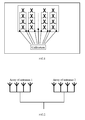
- dual polarized antennas may halve an array of antennas in width and thus lower the difficulty of engineering.
- the array of dual polarized antennas as referred to here is as illustrated in FIG. 1 , where array elements in two polarized directions are cross-arranged to thereby reduce the windward area of the array of antennas without reducing the number of antenna elements.
- FIG. 2 illustrates a schematic diagram of a multi-array antenna system with two arrays of antennas, where the arrays of antennas may be arrays of single-polarized antennas or multi-polarized antennas.
- Existing beam forming generally includes beam forming under a maximum power based criterion and beam forming under a maximum carrier to interference ratio based criterion, and weight coefficients derived in an algorithm of the former maximize the reception power at a receiver side.
- a global or local optimal solution may be derived dependent upon the varying specific implementation algorithm.
- w opt 1 is a value of w maximizing w H ⁇ R xx ⁇ w w H ⁇ w .
- a solution of the w maximizing the solution of equation (2) is unique and equal to an eigenvector corresponding to the maximum eigenvalue of the matrix method in which a global optimum solution can be derived.
- a simplified beam forming method is to search a preset set of weight vectors for a weight vector maximizing the solution of equation (2).
- Equations (3) and (5) represent two general methods for smart antenna beam forming, referred to respectively as Eigenvalue Based Beamforming (hereinafter referred to as an EBB algorithm) and Grid of Beamforming (hereinafter referred to as an GOB algorithm) .
- EBB algorithm Eigenvalue Based Beamforming
- GOB algorithm Grid of Beamforming
- All of the existing beam forming methods are applicable only to a single array of antennas with a small spacing.
- phase relationships between the arrays are not determined depending on an incident angle, therefore the existing grid of beamforming algorithm is inapplicable, and the eigenvalue based beamforming is also problematic.
- US 2005/0128983 A1 discloses a method grouping multiple transmission antennas by a base station in a mobile communication system which includes the multiple transmission antennas and multiple reception antennas, which further discloses: when a transmitter has Nt number of transmission antennas and a receiver has Nr number of reception antennas, Nt is larger than Nr in a forward link environment, the transmission antennas are classified into Nr number of groups using channel covariance so as to maximize the communication capacity of the transmitter; the channel covariance matrix is a channel value estimated by the receiver; and after the maximum eigenvalues of the sub-matrixes 'Rii' are respectively calculated, the transmission antennas are grouped so that a sum of the calculated maximum eigenvalues may be determined.
- US 2006/0234751 A1 and XP001133066 disclose both the water-filling method, in which lower
- embodiments of the invention provide a beam forming method and a device applicable to a multi-array antenna system.
- Embodiments of the invention provide a beam forming method applicable to a multi-array antenna system, as defined in claims 1 to 6.
- inventions further provide a beam forming device applicable to a multi-array antenna system, as defined in claims 7 and 8.
- a first example which provides a beam forming method, is based upon the traditional eigenvalue based beamforming algorithm and eliminates the unbalanced transmission power of antennas (an array of antennas) due to asymmetry of uplink and downlink channels and a beam forming gain loss due to limited power in the application of the traditional eigenvalue based beamforming algorithm to a multi-array antenna system.
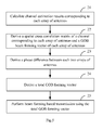
- the specific operations 11 to 14 of the first example are as illustrated in FIG. 3 .
- a spatial cross correlation matrix R of a joint channel of all arrays of antenna is derived from h ka n , and an eigenvector w ebb corresponding to the maximum eigenvalue of R is derived as a forming vector.
- R is derived from h ka n with equations (7), (8) and (9) for the purpose of illustrating a solution of the present example, and alternatively the spatial cross correlation matrix R of the joint channel of all arrays of antennas can be derived from h ka n in other methods, which are well known to those skilled in the art and detailed description of which is omitted here.
- w ebb is transformed mainly because arrays are independent of each other. Due to the independency of the arrays, transmission power is unbalanced among the arrays as a result of beam forming based transmission based on w ebb , for example, some of the arrays have high transmission power while the remaining arrays have low transmission power. Meanwhile, due to the inconsistence between uplink and downlink channels, when beam forming is performed for the downlink by using the ratio of power received over the uplink, the allocation of power is suboptimum, and power limitation may also arise when some of the antenna elements reach the maximum transmission power. w ebb may be transformed in two ways typically.
- w ebb may be transformed per array.
- the transformation per array refers to transformation of each antenna array as a whole.
- w n is transformed with its amplitude changed while its phase relationship remaining unchanged. Further, the ratio of transmission power of each antenna is maintained within the same array. For example, transmission power of 6 watts is allocated to four antenna elements in the same untransformed array and the ratio of their transmission power is 2:2:1:1 (that is, 2 watts for two of the antennas respectively and 1 watt for the remaining two antennas respectively). Although transmission power of 9 watts may be allocated to the four antenna elements in the transformed array, the ratio of their transmission power is still 2:2:1:1 (that is, 3 watts for two of the antennas respectively and 1.5 watt for the remaining two antennas respectively).
- w n when the power allocated to an antenna element in an array according to w n exceeds the maximum transmission power of the antenna element, it is possible to limit the transmission power of the antenna element to its maximum transmission power by the transformation while reallocating the power allocated according to w n minus the transmission power of the antenna element to an antenna element of other array.
- w n is also transformed with its amplitude changed while its phase relationship remaining unchanged.
- the reallocation may be performed in a maximum ratio principle, for example, if the power allocated to an antenna element in an array according to w n exceeds the transmission power of the antenna element by 1 watt, and an antenna element of other array is allocated with power less than its maximum transmission power by 0.8 watts, then power of 0.8 watts from the power of 1 watt is reallocated to the antenna element of the other array, and the remaining power of 0.2 watts is reallocated alike.
- the reallocation may be performed in an equal ratio principle, for example, if the power allocated to an antenna element in an array according to w n exceeds the transmission power of the antenna element by 1 watt, and there are four antenna elements in total in other array, then power of 0.25 watts from the power of 1 watt is reallocated to each of the four antenna elements respectively while ensuring that the transmission power of each of the four antenna elements does not exceed the maximum transmission power thereof.
- w ebb may be transformed per antenna.
- the transformation per antenna refers to separate transformation of each antenna element.
- w n is transformed with its amplitude changed while its phase relationship remaining unchanged.
- w n when the power allocated to an antenna element in an array according to w n exceeds the maximum transmission power of the antenna element, it is possible to limit the transmission power of the antenna element to its maximum transmission power by the transformation while reallocating the power allocated according to w n minus the transmission power of the antenna element to an antenna element of other array.
- w n is also transformed with its amplitude changed while its phase relationship remaining unchanged.
- the reallocation may be performed in a maximum or equal ratio principle while ensuring that the transmission power of each antenna element does not exceed the maximum transmission power thereof.
- Operation 14 beam forming based transmission is performed using the forming vector ⁇ n or ⁇ n ( k a ) obtained from the transformation as illustrated in FIG. 4 .
- a first embodiment of the invention relates to a beam forming method and is based upon the grid of beamforming method in the prior art.
- the traditional grid of beamforming method is not applicable if arrays are of a little correlation to each other, because a phase relationship between the arrays is not fixed for a specific incident angle. That is, no array response vector can be constructed jointly for a plurality of arrays, but the grid of beamforming algorithm can still be adopted in each array to derive its corresponding forming vector, and here a phase relationship between each two arrays is calculated in a method plurality of arrays.
- the implementation operations 21-25 are as follows.
- Operation 21 a channel estimation result corresponding to each array of antennas is calculated as in the operation 11 in the first example.
- Operation 23 a phase difference between each two arrays of antennas is derived from w gob n .
- a spatial cross correlation matrix of a joint channel of all arrays of antennas is derived.
- An eigenvector corresponding to the maximum eigenvalue of the spatial cross correlation matrix is derived.
- the derived forming vector is represented as w ebb , where,
- arg(•) represents an operation of deriving a complex phase angle.
- Operation 25 beam forming based transmission is performed by using the total GOB forming vector w gob as illustrated in FIG. 4 .
- a further embodiment of the invention relates to a beam forming method in which it is possible to switch between the foregoing two solutions adaptively in practice.
- the beam forming algorithms according to the invention have been practice, joint beam forming of plural of arrays and separate beam forming of each array with a diversity transmission algorithm can be switched in view of a specific channel environment.
- a second embodiment of the invention relates to a beam forming device applicable to a multi-array antenna system, which is structured as illustrated in FIG. 6 and includes:
- the transformation module 34 further includes:
- the device further includes:
- a further embodiment of the invention relates to a beam forming device, related to the method described in the first embodiment, applicable to a multi-array antenna system, which is structured as illustrated in FIG. 7 and includes:
- a third embodiment of the invention relates to a beam forming device applicable to a multi-array antenna system, which is structured as illustrated in FIG. 8 and includes:
Landscapes
- Engineering & Computer Science (AREA)
- Computer Networks & Wireless Communication (AREA)
- Signal Processing (AREA)
- Variable-Direction Aerials And Aerial Arrays (AREA)
- Radio Transmission System (AREA)
Claims (8)
- Strahlbildungsverfahren, das auf ein Multiarray-Antennensystem angewendet werden kann und das Folgendes umfasst:- Herleiten (21) einer Schätzung der Kanalimpulsantwort


 - Herleiten (22) einer räumlichen Querkorrelationsmatrix R n eines Kanals, der jedem Array von Antennen entspricht, aus
 - Herleiten (22) von Antennen-Array-Gewichtsvektoren
 • Definieren eines vorgegebenen Satzes von Array-Antwort-Vektoren a n (ϕ l ), die bestimmte Abtastwinkel ϕ l , l = 1 ... L abdecken, wobei L die Gesamtzahl von Abtastwinkeln darstellt,• Berechnen der Leistung
 • und Auswählen, als Antennen-Array-Gewichtsvektor
 - Herleiten (12) einer räumlichen Querkorrelationsmatrix R eines gemeinsamen Kanals aller Arrays von Antennen aus
 - Herleiten (12) eines Eigenvektors w ebb , der dem maximalen Eigenwert von R entspricht, wobei
 - Herleiten (23) einer Phasendifferenz Δϕ n zwischen jeweils zwei Arrays von Antennen aus
 - Herleiten (24) eines Gesamt-GOB-Antennen-A-rray-Gewichtsvektors w gob aller Arrays von Antennen aus
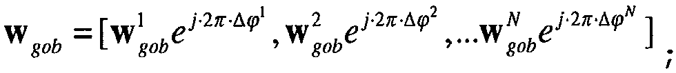 - Ausführen (25) einer strahlbildungsbasierten Übertragung unter Verwendung von w gob .
 - Verfahren nach Anspruch 1, das des Weiteren Folgendes umfasst:- Transformieren (13) von w ebb je Array oder je Antenne durch Ändern lediglich seiner Amplitude;- Herleiten von pebb aus dem transformierten w ebb und R als
 - Herleiten von pgob aus R und
 - falls pgob < pebb' Auswählen des transformierten w ebb als den Antennen-Array-Gewichtsvektor; anderenfalls Auswählen von w gob als den Antennen-Array-Gewichtsvektor.
 - Verfahren nach Anspruch 2, wobei das Transformieren von w ebb je Array durch Ändern lediglich seiner Amplitude Folgendes umfasst:- Herleiten von Antennen-Array-Gewichtsvektoren wn der Arrays von Antennen aus w ebb , und- Transformieren von wn in Amplitude in die Antennen-Array-Gewichtsvektoren ŵ n als

- Verfahren nach Anspruch 2, wobei das Transformieren von w ebb je Antenne durch Ändern lediglich seiner Amplitude Folgendes umfasst:- Herleiten eines Antennen-Array-Gewichtsvektors


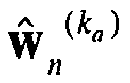


- Verfahren nach Anspruch 2, wobei, wenn die Leistung, die einem Antennenelement gemäß dem Antennen-Array-Gewichtsvektor des transformierten w ebb zugewiesen wird, die maximale Sendeleistung des Antennenelements überschreitet, das Antennenelement mit seiner maximalen Sendeleistung sendet, und die zugewiesene Leistung minus der maximalen Sendeleistung des Antennenelements einem Antennenelement eines anderes Arrays neu zugewiesen wird, während sichergestellt wird, dass die Sendeleistung jedes Antennenelements nicht seine maximale Sendeleistung überschreitet.
- Verfahren nach Anspruch 5, wobei die Neuzuweisung nach einem Prinzip des maximalen oder gleichen Verhältnisses ausgeführt wird.
- Strahlbildungsvorrichtung, die in einem Multiarray-Antennensystem angewendet werden kann und die Folgendes umfasst:- ein


 - ein R n -Herleitungsmodul (42), das dafür ausgebildet ist, aus dem durch das


 - ein
- ein


 - ein R-Herleitungsmodul (32), das dafür ausgebildet ist, aus dem durch das


 - ein w ebb -Herleitungsmodul (33), das dafür ausgebildet ist, einen Eigenvektor w ebb , der dem durch das R-Herleitungsmodul (32) hergeleiteten maximalen Eigenwert von R entspricht, herzuleiten, wobei
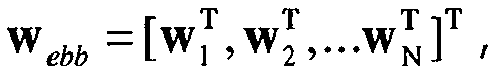 - ein Δϕ n -Herleitungsmodul (44), das dafür ausgebildet ist, eine Phasendifferenz Δϕ n zwischen jeweils zwei Arrays von Antennen aus dem durch das

 - ein w gob -Herleitungsmodul (45), das dafür ausgebildet ist, einen Gesamt-GOB-Antennen-Array-Gewichtsvektor w gob aller Arrays von Antennen aus dem durch das

 - ein w gob -strahlbildungsbasiertes Übertragungsmodul (46), das dafür ausgebildet ist, eine strahlbildungsbasierte Übertragung unter Verwendung des durch das w gob -Herleitungsmodul (45) transformierten w gob auszuführen.
 - Vorrichtung nach Anspruch 7, das des Weiteren ein Transformationsmodul (34) umfasst, das dafür ausgebildet ist, w ebb je Array (341) oder je Antenne (342) durch Ändern lediglich seiner Amplitude zu transformieren, wobei die Vorrichtung des Weiteren Folgendes umfasst:- ein pebb -Herleitungsmodul (51), das dafür ausgebildet ist, pebb aus dem durch das Transformationsmodul (34) hergeleiteten transformierten w ebb und R als
 - ein pgob -Herleitungsmodul (52), das dafür ausgebildet ist, pgob aus R und
 - ein Vergleichsmodul (53), das dafür ausgebildet ist, das transformierte w ebb als den Antennen-Array-Gewichtsvektor auszuwählen, falls das durch das pgob -Herleitungsmodul (52) hergeleitete pgob unter dem durch das pebb -Herleitungsmodul (51) hergeleiteten pebb liegt, anderenfalls Auswählen von w gob als den Antennen-Array-Gewichtsvektor.
Applications Claiming Priority (2)
| Application Number | Priority Date | Filing Date | Title |
|---|---|---|---|
| CN 200810056225 CN101488792B (zh) | 2008-01-15 | 2008-01-15 | 一种波束赋形方法及装置 |
| PCT/CN2009/000054 WO2009092289A1 (zh) | 2008-01-15 | 2009-01-15 | 一种波束赋形方法及装置 |
Publications (3)
| Publication Number | Publication Date |
|---|---|
| EP2246937A1 EP2246937A1 (de) | 2010-11-03 |
| EP2246937A4 EP2246937A4 (de) | 2013-11-06 |
| EP2246937B1 true EP2246937B1 (de) | 2015-08-12 |
Family
ID=40891493
Family Applications (1)
| Application Number | Title | Priority Date | Filing Date |
|---|---|---|---|
| EP09704251.9A Active EP2246937B1 (de) | 2008-01-15 | 2009-01-15 | Strahlformungsverfahren und einrichtung |
Country Status (4)
| Country | Link |
|---|---|
| EP (1) | EP2246937B1 (de) |
| KR (1) | KR101152872B1 (de) |
| CN (1) | CN101488792B (de) |
| WO (1) | WO2009092289A1 (de) |
Cited By (2)
| Publication number | Priority date | Publication date | Assignee | Title |
|---|---|---|---|---|
| US10581504B2 (en) | 2015-12-31 | 2020-03-03 | Huawei Technologies Co., Ltd. | Beamforming method, receiver, transmitter, and system |
| WO2023086706A1 (en) * | 2021-11-12 | 2023-05-19 | Qualcomm Incorporated | Communications using dynamic beam weights |
Families Citing this family (15)
| Publication number | Priority date | Publication date | Assignee | Title |
|---|---|---|---|---|
| CN102082594B (zh) * | 2009-11-30 | 2013-09-11 | 华为技术有限公司 | 波束形成方法、装置和发射系统 |
| PH12013500795A1 (en) | 2010-12-17 | 2013-06-17 | Ericsson Telefon Ab L M | Beamforming method, apparatus for polarized antenna array and radio communication device and system thereof |
| JP4730677B1 (ja) * | 2011-01-27 | 2011-07-20 | 日本電気株式会社 | 情報処理装置及び情報処理方法並びに情報処理プログラム |
| CN103152085B (zh) * | 2011-12-06 | 2018-02-02 | 中兴通讯股份有限公司 | 三维波束赋形的权值获取方法和装置 |
| CN103368621B (zh) * | 2012-03-26 | 2017-12-15 | 华为技术有限公司 | 信号的处理方法和设备 |
| CN103427886B (zh) * | 2012-05-17 | 2016-12-07 | 电信科学技术研究院 | 一种双流波束赋形方法及装置 |
| CN102959796B (zh) * | 2012-08-29 | 2015-04-08 | 华为技术有限公司 | 模块化天线装置及其配置方法 |
| CN105322993B (zh) * | 2014-07-28 | 2018-08-10 | 普天信息技术有限公司 | 一种广播波束赋形方法 |
| CN106575986B (zh) * | 2014-08-13 | 2021-02-12 | 诺基亚通信公司 | 调节用于基于特征值的波束形成的传输功率的方法 |
| WO2016141514A1 (en) * | 2015-03-06 | 2016-09-15 | He Xiaoxi | Beamforming method and beamforming apparatus |
| WO2017008268A1 (en) * | 2015-07-15 | 2017-01-19 | Nec Corporation | Method and apparatus for performing beamforming |
| CN109490875B (zh) * | 2017-09-12 | 2022-10-14 | 启碁科技股份有限公司 | 角度估测方法及雷达系统 |
| CN108337029A (zh) * | 2017-12-29 | 2018-07-27 | 南京理工大学 | 安全无线传输中自适应稳健零空间投影波束赋形方法 |
| CN108495325A (zh) * | 2018-03-28 | 2018-09-04 | 南京理工大学 | 安全方向调制网络中最大化安全速率的功率分配策略 |
| US12212388B2 (en) * | 2023-05-26 | 2025-01-28 | Qualcomm Incorporated | Sensing based dynamic beams |
Family Cites Families (8)
| Publication number | Priority date | Publication date | Assignee | Title |
|---|---|---|---|---|
| KR100493068B1 (ko) * | 2000-03-08 | 2005-06-02 | 삼성전자주식회사 | 이동통신시스템에서 피드백 정보를 이용하는 반맹목적방식의 송신안테나어레이 장치 및 방법 |
| KR100375826B1 (ko) * | 2000-11-15 | 2003-03-15 | 한국전자통신연구원 | 배열 안테나를 이용한 대역 확산 코드 분할 다중 접속기지국 시스템의 순방향 빔 형성 가중치 연산 장치, 이를이용한 순방향 빔 형성 시스템 및 그 방법 |
| KR100580762B1 (ko) * | 2003-07-25 | 2006-05-15 | 엘지전자 주식회사 | 이동통신 시스템에서의 다운링크 빔 형성 방법 |
| KR100981554B1 (ko) * | 2003-11-13 | 2010-09-10 | 한국과학기술원 | 다중 송수신 안테나들을 구비하는 이동통신시스템에서,송신 안테나들을 그룹핑하여 신호를 전송하는 방법 |
| US20060234751A1 (en) * | 2005-04-19 | 2006-10-19 | Samsung Electronics Co., Ltd. | Power loading method and apparatus for throughput enhancement in MIMO systems |
| CN100512052C (zh) * | 2005-04-28 | 2009-07-08 | 上海原动力通信科技有限公司 | 一种实现干扰抑制的波束赋形方法 |
| CN1925362A (zh) * | 2005-08-29 | 2007-03-07 | 中兴通讯股份有限公司 | 一种基于均匀线阵的智能天线的实现方法 |
| CN100547945C (zh) * | 2006-03-27 | 2009-10-07 | 普天信息技术研究院 | 一种下行波束赋形的方法及装置 |
-
2008
- 2008-01-15 CN CN 200810056225 patent/CN101488792B/zh active Active
-
2009
- 2009-01-15 KR KR1020107018041A patent/KR101152872B1/ko active Active
- 2009-01-15 WO PCT/CN2009/000054 patent/WO2009092289A1/zh not_active Ceased
- 2009-01-15 EP EP09704251.9A patent/EP2246937B1/de active Active
Non-Patent Citations (1)
| Title |
|---|
| KHALIGHI M A ET AL: "CAPACITY OF WIRELESS COMMUNICATIONS SYSTEMS EMPLOYING ANTENNA ARRAYS, A TUTORIAL STUDY", WIRELESS PERSONAL COMMUNICATIONS, SPRINGER, DORDRECHT, NL, vol. 23, no. 3, 1 December 2002 (2002-12-01), pages 321 - 352, XP001133096, ISSN: 0929-6212, DOI: 10.1023/A:1021211513679 * |
Cited By (3)
| Publication number | Priority date | Publication date | Assignee | Title |
|---|---|---|---|---|
| US10581504B2 (en) | 2015-12-31 | 2020-03-03 | Huawei Technologies Co., Ltd. | Beamforming method, receiver, transmitter, and system |
| WO2023086706A1 (en) * | 2021-11-12 | 2023-05-19 | Qualcomm Incorporated | Communications using dynamic beam weights |
| US11728869B2 (en) | 2021-11-12 | 2023-08-15 | Qualcomm Incorporated | Communications using dynamic beam weights |
Also Published As
| Publication number | Publication date |
|---|---|
| CN101488792A (zh) | 2009-07-22 |
| WO2009092289A1 (zh) | 2009-07-30 |
| CN101488792B (zh) | 2012-10-31 |
| KR20100117605A (ko) | 2010-11-03 |
| KR101152872B1 (ko) | 2012-06-12 |
| EP2246937A1 (de) | 2010-11-03 |
| EP2246937A4 (de) | 2013-11-06 |
Similar Documents
| Publication | Publication Date | Title |
|---|---|---|
| EP2246937B1 (de) | Strahlformungsverfahren und einrichtung | |
| EP2777172B1 (de) | Verfahren, vorrichtung und system zur dynamischen konfiguration von gruppenantennen | |
| US8571127B2 (en) | MIMO transmission with rank adaptation for multi-gigabit 60 GHz wireless | |
| Paul et al. | A novel beamspace channel estimation technique for millimeter wave massive MIMO systems | |
| US8718665B2 (en) | Method and apparatus of transmitting data in coordinated multi-cell wireless communication system | |
| US8175184B2 (en) | Method for transmitting beam forming information and a method for tracking position of a mobile station in multi input multi output system using codebook-based beam forming scheme | |
| EP3123626B1 (de) | Verfahren zur durchführung einer hybriden strahlformung in einem drahtloskommunikationssystem und vorrichtung dafür | |
| US9413474B2 (en) | Efficient large-scale multiple input multiple output communications | |
| CN102624496B (zh) | 预编码处理方法、基站和通信系统 | |
| US9252864B2 (en) | Method and apparatus for fast beam-link construction in mobile communication system | |
| CN101459457B (zh) | 一种波束赋形方法 | |
| US9160433B2 (en) | Beam codebook generation method, beam search method and related apparatuses | |
| US8750401B2 (en) | Sequential transmission multi-beamforming method with low complexity using Hadamard matrix | |
| US12255708B2 (en) | Transmission of MU-MIMO signals | |
| CN101615943B (zh) | 智能天线多子阵列系统的波达角估计方法 | |
| Wang et al. | Sensing-aided hybrid precoding for efficient terahertz wideband communications in multiuser high-data-rate IoT | |
| EP3185440B1 (de) | Doa-bf-gewichtsschätzungsverfahren und vorrichtung für antennensystem mit dualer polarisierung | |
| CN104639220B (zh) | 一种采用智能天线的信号收发装置和方法 | |
| KR20090043174A (ko) | 프리코딩을 이용한 송신 데이터 생성 방법, 생성된 송신데이터 전송 방법, 생성된 송신 데이터 수신 방법 및 그전송 장치 | |
| CN102223168B (zh) | 基于阵列天线和mimo联合传输波束成形方法 | |
| Jha et al. | Optimizing Synchronization Signal Block Transmissions for Sum-Rate Maximization in Sub-Connected Hybrid Beamforming Systems | |
| Elnoubi et al. | Minimum bit error rate beamforming combined with space-time block coding | |
| Li et al. | Probing Power and Minimum Rate Maximization for RIS-Aided ISAC System | |
| Torcolacci et al. | Scalable RIS-Aided Beamforming Strategies for Near-Field MU-MISO via Multi-Antenna Feeder | |
| Gaya et al. | Modeling, calculating and capacity enhancement of a Rayleigh fading MIMO channel |
Legal Events
| Date | Code | Title | Description |
|---|---|---|---|
| PUAI | Public reference made under article 153(3) epc to a published international application that has entered the european phase |
Free format text: ORIGINAL CODE: 0009012 |
|
| 17P | Request for examination filed |
Effective date: 20100812 |
|
| AK | Designated contracting states |
Kind code of ref document: A1 Designated state(s): AT BE BG CH CY CZ DE DK EE ES FI FR GB GR HR HU IE IS IT LI LT LU LV MC MK MT NL NO PL PT RO SE SI SK TR |
|
| AX | Request for extension of the european patent |
Extension state: AL BA RS |
|
| DAX | Request for extension of the european patent (deleted) | ||
| RAP1 | Party data changed (applicant data changed or rights of an application transferred) |
Owner name: CHINA ACADEMY OF TELECOMMUNICATIONS TECHNOLOGY |
|
| A4 | Supplementary search report drawn up and despatched |
Effective date: 20131004 |
|
| RIC1 | Information provided on ipc code assigned before grant |
Ipc: H04W 52/42 20090101ALI20130927BHEP Ipc: H04B 7/08 20060101ALI20130927BHEP Ipc: H01Q 21/29 20060101AFI20130927BHEP Ipc: H04B 7/04 20060101ALI20130927BHEP Ipc: H01Q 3/26 20060101ALI20130927BHEP Ipc: H04B 7/06 20060101ALI20130927BHEP |
|
| 17Q | First examination report despatched |
Effective date: 20140610 |
|
| GRAP | Despatch of communication of intention to grant a patent |
Free format text: ORIGINAL CODE: EPIDOSNIGR1 |
|
| RIC1 | Information provided on ipc code assigned before grant |
Ipc: H01Q 3/26 20060101AFI20150112BHEP Ipc: H04W 52/42 20090101ALN20150112BHEP Ipc: H04B 7/10 20060101ALN20150112BHEP Ipc: H04B 7/04 20060101ALI20150112BHEP Ipc: H04B 7/06 20060101ALN20150112BHEP |
|
| INTG | Intention to grant announced |
Effective date: 20150123 |
|
| REG | Reference to a national code |
Ref country code: DE Ref legal event code: R079 Ref document number: 602009032792 Country of ref document: DE Free format text: PREVIOUS MAIN CLASS: H01Q0021290000 Ipc: H01Q0003260000 |
|
| GRAP | Despatch of communication of intention to grant a patent |
Free format text: ORIGINAL CODE: EPIDOSNIGR1 |
|
| GRAS | Grant fee paid |
Free format text: ORIGINAL CODE: EPIDOSNIGR3 |
|
| RIC1 | Information provided on ipc code assigned before grant |
Ipc: H04B 7/10 20060101ALN20150604BHEP Ipc: H04W 52/42 20090101ALN20150604BHEP Ipc: H01Q 3/26 20060101AFI20150604BHEP Ipc: H04B 7/04 20060101ALI20150604BHEP Ipc: H04B 7/06 20060101ALN20150604BHEP |
|
| GRAA | (expected) grant |
Free format text: ORIGINAL CODE: 0009210 |
|
| INTG | Intention to grant announced |
Effective date: 20150615 |
|
| AK | Designated contracting states |
Kind code of ref document: B1 Designated state(s): AT BE BG CH CY CZ DE DK EE ES FI FR GB GR HR HU IE IS IT LI LT LU LV MC MK MT NL NO PL PT RO SE SI SK TR |
|
| REG | Reference to a national code |
Ref country code: GB Ref legal event code: FG4D |
|
| REG | Reference to a national code |
Ref country code: CH Ref legal event code: EP |
|
| REG | Reference to a national code |
Ref country code: AT Ref legal event code: REF Ref document number: 742864 Country of ref document: AT Kind code of ref document: T Effective date: 20150815 |
|
| REG | Reference to a national code |
Ref country code: IE Ref legal event code: FG4D |
|
| REG | Reference to a national code |
Ref country code: DE Ref legal event code: R096 Ref document number: 602009032792 Country of ref document: DE |
|
| REG | Reference to a national code |
Ref country code: LT Ref legal event code: MG4D |
|
| REG | Reference to a national code |
Ref country code: AT Ref legal event code: MK05 Ref document number: 742864 Country of ref document: AT Kind code of ref document: T Effective date: 20150812 |
|
| REG | Reference to a national code |
Ref country code: NL Ref legal event code: MP Effective date: 20150812 |
|
| PG25 | Lapsed in a contracting state [announced via postgrant information from national office to epo] |
Ref country code: LV Free format text: LAPSE BECAUSE OF FAILURE TO SUBMIT A TRANSLATION OF THE DESCRIPTION OR TO PAY THE FEE WITHIN THE PRESCRIBED TIME-LIMIT Effective date: 20150812 Ref country code: LT Free format text: LAPSE BECAUSE OF FAILURE TO SUBMIT A TRANSLATION OF THE DESCRIPTION OR TO PAY THE FEE WITHIN THE PRESCRIBED TIME-LIMIT Effective date: 20150812 Ref country code: GR Free format text: LAPSE BECAUSE OF FAILURE TO SUBMIT A TRANSLATION OF THE DESCRIPTION OR TO PAY THE FEE WITHIN THE PRESCRIBED TIME-LIMIT Effective date: 20151113 Ref country code: FI Free format text: LAPSE BECAUSE OF FAILURE TO SUBMIT A TRANSLATION OF THE DESCRIPTION OR TO PAY THE FEE WITHIN THE PRESCRIBED TIME-LIMIT Effective date: 20150812 Ref country code: NO Free format text: LAPSE BECAUSE OF FAILURE TO SUBMIT A TRANSLATION OF THE DESCRIPTION OR TO PAY THE FEE WITHIN THE PRESCRIBED TIME-LIMIT Effective date: 20151112 |
|
| REG | Reference to a national code |
Ref country code: FR Ref legal event code: PLFP Year of fee payment: 8 |
|
| PG25 | Lapsed in a contracting state [announced via postgrant information from national office to epo] |
Ref country code: SE Free format text: LAPSE BECAUSE OF FAILURE TO SUBMIT A TRANSLATION OF THE DESCRIPTION OR TO PAY THE FEE WITHIN THE PRESCRIBED TIME-LIMIT Effective date: 20150812 Ref country code: AT Free format text: LAPSE BECAUSE OF FAILURE TO SUBMIT A TRANSLATION OF THE DESCRIPTION OR TO PAY THE FEE WITHIN THE PRESCRIBED TIME-LIMIT Effective date: 20150812 Ref country code: HR Free format text: LAPSE BECAUSE OF FAILURE TO SUBMIT A TRANSLATION OF THE DESCRIPTION OR TO PAY THE FEE WITHIN THE PRESCRIBED TIME-LIMIT Effective date: 20150812 Ref country code: PL Free format text: LAPSE BECAUSE OF FAILURE TO SUBMIT A TRANSLATION OF THE DESCRIPTION OR TO PAY THE FEE WITHIN THE PRESCRIBED TIME-LIMIT Effective date: 20150812 Ref country code: PT Free format text: LAPSE BECAUSE OF FAILURE TO SUBMIT A TRANSLATION OF THE DESCRIPTION OR TO PAY THE FEE WITHIN THE PRESCRIBED TIME-LIMIT Effective date: 20151214 Ref country code: IS Free format text: LAPSE BECAUSE OF FAILURE TO SUBMIT A TRANSLATION OF THE DESCRIPTION OR TO PAY THE FEE WITHIN THE PRESCRIBED TIME-LIMIT Effective date: 20151212 Ref country code: ES Free format text: LAPSE BECAUSE OF FAILURE TO SUBMIT A TRANSLATION OF THE DESCRIPTION OR TO PAY THE FEE WITHIN THE PRESCRIBED TIME-LIMIT Effective date: 20150812 |
|
| PG25 | Lapsed in a contracting state [announced via postgrant information from national office to epo] |
Ref country code: NL Free format text: LAPSE BECAUSE OF FAILURE TO SUBMIT A TRANSLATION OF THE DESCRIPTION OR TO PAY THE FEE WITHIN THE PRESCRIBED TIME-LIMIT Effective date: 20150812 |
|
| PG25 | Lapsed in a contracting state [announced via postgrant information from national office to epo] |
Ref country code: EE Free format text: LAPSE BECAUSE OF FAILURE TO SUBMIT A TRANSLATION OF THE DESCRIPTION OR TO PAY THE FEE WITHIN THE PRESCRIBED TIME-LIMIT Effective date: 20150812 Ref country code: SK Free format text: LAPSE BECAUSE OF FAILURE TO SUBMIT A TRANSLATION OF THE DESCRIPTION OR TO PAY THE FEE WITHIN THE PRESCRIBED TIME-LIMIT Effective date: 20150812 Ref country code: CZ Free format text: LAPSE BECAUSE OF FAILURE TO SUBMIT A TRANSLATION OF THE DESCRIPTION OR TO PAY THE FEE WITHIN THE PRESCRIBED TIME-LIMIT Effective date: 20150812 Ref country code: IT Free format text: LAPSE BECAUSE OF FAILURE TO SUBMIT A TRANSLATION OF THE DESCRIPTION OR TO PAY THE FEE WITHIN THE PRESCRIBED TIME-LIMIT Effective date: 20150812 Ref country code: DK Free format text: LAPSE BECAUSE OF FAILURE TO SUBMIT A TRANSLATION OF THE DESCRIPTION OR TO PAY THE FEE WITHIN THE PRESCRIBED TIME-LIMIT Effective date: 20150812 |
|
| REG | Reference to a national code |
Ref country code: DE Ref legal event code: R097 Ref document number: 602009032792 Country of ref document: DE |
|
| PG25 | Lapsed in a contracting state [announced via postgrant information from national office to epo] |
Ref country code: RO Free format text: LAPSE BECAUSE OF FAILURE TO SUBMIT A TRANSLATION OF THE DESCRIPTION OR TO PAY THE FEE WITHIN THE PRESCRIBED TIME-LIMIT Effective date: 20150812 |
|
| PLBE | No opposition filed within time limit |
Free format text: ORIGINAL CODE: 0009261 |
|
| STAA | Information on the status of an ep patent application or granted ep patent |
Free format text: STATUS: NO OPPOSITION FILED WITHIN TIME LIMIT |
|
| 26N | No opposition filed |
Effective date: 20160513 |
|
| PG25 | Lapsed in a contracting state [announced via postgrant information from national office to epo] |
Ref country code: SI Free format text: LAPSE BECAUSE OF FAILURE TO SUBMIT A TRANSLATION OF THE DESCRIPTION OR TO PAY THE FEE WITHIN THE PRESCRIBED TIME-LIMIT Effective date: 20150812 Ref country code: LU Free format text: LAPSE BECAUSE OF FAILURE TO SUBMIT A TRANSLATION OF THE DESCRIPTION OR TO PAY THE FEE WITHIN THE PRESCRIBED TIME-LIMIT Effective date: 20160115 |
|
| REG | Reference to a national code |
Ref country code: CH Ref legal event code: PL |
|
| PG25 | Lapsed in a contracting state [announced via postgrant information from national office to epo] |
Ref country code: MC Free format text: LAPSE BECAUSE OF FAILURE TO SUBMIT A TRANSLATION OF THE DESCRIPTION OR TO PAY THE FEE WITHIN THE PRESCRIBED TIME-LIMIT Effective date: 20150812 |
|
| PG25 | Lapsed in a contracting state [announced via postgrant information from national office to epo] |
Ref country code: CH Free format text: LAPSE BECAUSE OF NON-PAYMENT OF DUE FEES Effective date: 20160131 Ref country code: LI Free format text: LAPSE BECAUSE OF NON-PAYMENT OF DUE FEES Effective date: 20160131 |
|
| REG | Reference to a national code |
Ref country code: IE Ref legal event code: MM4A |
|
| PG25 | Lapsed in a contracting state [announced via postgrant information from national office to epo] |
Ref country code: IE Free format text: LAPSE BECAUSE OF NON-PAYMENT OF DUE FEES Effective date: 20160115 |
|
| REG | Reference to a national code |
Ref country code: FR Ref legal event code: PLFP Year of fee payment: 9 |
|
| PG25 | Lapsed in a contracting state [announced via postgrant information from national office to epo] |
Ref country code: MT Free format text: LAPSE BECAUSE OF FAILURE TO SUBMIT A TRANSLATION OF THE DESCRIPTION OR TO PAY THE FEE WITHIN THE PRESCRIBED TIME-LIMIT Effective date: 20150812 |
|
| REG | Reference to a national code |
Ref country code: FR Ref legal event code: PLFP Year of fee payment: 10 |
|
| PG25 | Lapsed in a contracting state [announced via postgrant information from national office to epo] |
Ref country code: CY Free format text: LAPSE BECAUSE OF FAILURE TO SUBMIT A TRANSLATION OF THE DESCRIPTION OR TO PAY THE FEE WITHIN THE PRESCRIBED TIME-LIMIT Effective date: 20150812 Ref country code: HU Free format text: LAPSE BECAUSE OF FAILURE TO SUBMIT A TRANSLATION OF THE DESCRIPTION OR TO PAY THE FEE WITHIN THE PRESCRIBED TIME-LIMIT; INVALID AB INITIO Effective date: 20090115 |
|
| PG25 | Lapsed in a contracting state [announced via postgrant information from national office to epo] |
Ref country code: TR Free format text: LAPSE BECAUSE OF FAILURE TO SUBMIT A TRANSLATION OF THE DESCRIPTION OR TO PAY THE FEE WITHIN THE PRESCRIBED TIME-LIMIT Effective date: 20150812 Ref country code: MT Free format text: LAPSE BECAUSE OF FAILURE TO SUBMIT A TRANSLATION OF THE DESCRIPTION OR TO PAY THE FEE WITHIN THE PRESCRIBED TIME-LIMIT Effective date: 20160131 Ref country code: MK Free format text: LAPSE BECAUSE OF FAILURE TO SUBMIT A TRANSLATION OF THE DESCRIPTION OR TO PAY THE FEE WITHIN THE PRESCRIBED TIME-LIMIT Effective date: 20150812 |
|
| PG25 | Lapsed in a contracting state [announced via postgrant information from national office to epo] |
Ref country code: BG Free format text: LAPSE BECAUSE OF FAILURE TO SUBMIT A TRANSLATION OF THE DESCRIPTION OR TO PAY THE FEE WITHIN THE PRESCRIBED TIME-LIMIT Effective date: 20150812 |
|
| REG | Reference to a national code |
Ref country code: DE Ref legal event code: R081 Ref document number: 602009032792 Country of ref document: DE Owner name: DATANG MOBILE COMMUNICATIONS EQUIPMENT CO., LT, CN Free format text: FORMER OWNER: CHINA ACADEMY OF TELECOMMUNICATIONS TECHNOLOGY, BEIJING, CN |
|
| REG | Reference to a national code |
Ref country code: BE Ref legal event code: PD Owner name: DATANG MOBILE COMMUNICATIONS EQUIPMENT CO., LTD.; CN Free format text: DETAILS ASSIGNMENT: CHANGE OF OWNER(S), ASSIGNMENT; FORMER OWNER NAME: CHINA ACADEMY OF TELECOMMUNICATIONS TECHNOLOGY Effective date: 20210816 |
|
| REG | Reference to a national code |
Ref country code: GB Ref legal event code: 732E Free format text: REGISTERED BETWEEN 20211007 AND 20211013 |
|
| PGFP | Annual fee paid to national office [announced via postgrant information from national office to epo] |
Ref country code: DE Payment date: 20250121 Year of fee payment: 17 |
|
| PGFP | Annual fee paid to national office [announced via postgrant information from national office to epo] |
Ref country code: BE Payment date: 20250121 Year of fee payment: 17 |
|
| PGFP | Annual fee paid to national office [announced via postgrant information from national office to epo] |
Ref country code: FR Payment date: 20250127 Year of fee payment: 17 |
|
| PGFP | Annual fee paid to national office [announced via postgrant information from national office to epo] |
Ref country code: GB Payment date: 20250128 Year of fee payment: 17 |