EP2246865A2 - Device for the cross-winding of wire on spools in general - Google Patents
Device for the cross-winding of wire on spools in general Download PDFInfo
- Publication number
- EP2246865A2 EP2246865A2 EP10159417A EP10159417A EP2246865A2 EP 2246865 A2 EP2246865 A2 EP 2246865A2 EP 10159417 A EP10159417 A EP 10159417A EP 10159417 A EP10159417 A EP 10159417A EP 2246865 A2 EP2246865 A2 EP 2246865A2
- Authority
- EP
- European Patent Office
- Prior art keywords
- spool
- clamp
- wire
- axis
- pair
- Prior art date
- Legal status (The legal status is an assumption and is not a legal conclusion. Google has not performed a legal analysis and makes no representation as to the accuracy of the status listed.)
- Withdrawn
Links
- 238000004804 winding Methods 0.000 title claims abstract description 19
- 210000000078 claw Anatomy 0.000 claims abstract description 17
- 230000001360 synchronised effect Effects 0.000 claims abstract description 6
- 230000008878 coupling Effects 0.000 claims description 2
- 238000010168 coupling process Methods 0.000 claims description 2
- 238000005859 coupling reaction Methods 0.000 claims description 2
- 230000014759 maintenance of location Effects 0.000 claims 1
- 230000000670 limiting effect Effects 0.000 description 2
- 230000002860 competitive effect Effects 0.000 description 1
- 238000010276 construction Methods 0.000 description 1
- 238000012986 modification Methods 0.000 description 1
- 230000004048 modification Effects 0.000 description 1
- 230000000717 retained effect Effects 0.000 description 1
Images


Classifications
-
- H—ELECTRICITY
- H01—ELECTRIC ELEMENTS
- H01F—MAGNETS; INDUCTANCES; TRANSFORMERS; SELECTION OF MATERIALS FOR THEIR MAGNETIC PROPERTIES
- H01F41/00—Apparatus or processes specially adapted for manufacturing or assembling magnets, inductances or transformers; Apparatus or processes specially adapted for manufacturing materials characterised by their magnetic properties
- H01F41/02—Apparatus or processes specially adapted for manufacturing or assembling magnets, inductances or transformers; Apparatus or processes specially adapted for manufacturing materials characterised by their magnetic properties for manufacturing cores, coils, or magnets
- H01F41/04—Apparatus or processes specially adapted for manufacturing or assembling magnets, inductances or transformers; Apparatus or processes specially adapted for manufacturing materials characterised by their magnetic properties for manufacturing cores, coils, or magnets for manufacturing coils
- H01F41/06—Coil winding
- H01F41/082—Devices for guiding or positioning the winding material on the former
-
- H—ELECTRICITY
- H01—ELECTRIC ELEMENTS
- H01F—MAGNETS; INDUCTANCES; TRANSFORMERS; SELECTION OF MATERIALS FOR THEIR MAGNETIC PROPERTIES
- H01F41/00—Apparatus or processes specially adapted for manufacturing or assembling magnets, inductances or transformers; Apparatus or processes specially adapted for manufacturing materials characterised by their magnetic properties
- H01F41/02—Apparatus or processes specially adapted for manufacturing or assembling magnets, inductances or transformers; Apparatus or processes specially adapted for manufacturing materials characterised by their magnetic properties for manufacturing cores, coils, or magnets
- H01F41/04—Apparatus or processes specially adapted for manufacturing or assembling magnets, inductances or transformers; Apparatus or processes specially adapted for manufacturing materials characterised by their magnetic properties for manufacturing cores, coils, or magnets for manufacturing coils
- H01F41/06—Coil winding
- H01F41/064—Winding non-flat conductive wires, e.g. rods, cables or cords
-
- H—ELECTRICITY
- H01—ELECTRIC ELEMENTS
- H01F—MAGNETS; INDUCTANCES; TRANSFORMERS; SELECTION OF MATERIALS FOR THEIR MAGNETIC PROPERTIES
- H01F41/00—Apparatus or processes specially adapted for manufacturing or assembling magnets, inductances or transformers; Apparatus or processes specially adapted for manufacturing materials characterised by their magnetic properties
- H01F41/02—Apparatus or processes specially adapted for manufacturing or assembling magnets, inductances or transformers; Apparatus or processes specially adapted for manufacturing materials characterised by their magnetic properties for manufacturing cores, coils, or magnets
- H01F41/04—Apparatus or processes specially adapted for manufacturing or assembling magnets, inductances or transformers; Apparatus or processes specially adapted for manufacturing materials characterised by their magnetic properties for manufacturing cores, coils, or magnets for manufacturing coils
- H01F41/06—Coil winding
- H01F41/098—Mandrels; Formers
Definitions
- an object of the invention is to provide a device in which it is possible to achieve a winding in which the correct positioning of the several turns in all the component layers is always ensured.
- a particular feature of the device according to the invention consists in that there is a clamp 20, which is arranged on the axis of the spool 5 and is supported by a movable frame 30, which can slide in a direction that is parallel to the axis of the clamp or the clamps 20, which can be supported by the cross-member 31 of the frame 30.
- a clamp 20 which is arranged on the axis of the spool 5 and is supported by a movable frame 30, which can slide in a direction that is parallel to the axis of the clamp or the clamps 20, which can be supported by the cross-member 31 of the frame 30.
- For translational motion there are means 35 for axial translational motion which are provided, for example, by means of brushless motors that operate on translation joints associated with ball screws, which cause a linear movement.
- the movable frame 30 is made to slide so that the engagement body 50 moves away from the spindle and the spool can be extracted manually or by way of automatic means.
Landscapes
- Engineering & Computer Science (AREA)
- Power Engineering (AREA)
- Manufacturing & Machinery (AREA)
- Electrical Discharge Machining, Electrochemical Machining, And Combined Machining (AREA)
- Reduction Rolling/Reduction Stand/Operation Of Reduction Machine (AREA)
- Storage Of Web-Like Or Filamentary Materials (AREA)
- Coil Winding Methods And Apparatuses (AREA)
Abstract
Description
- The present invention relates to a device for the cross-winding of wire on spools in general.
- As is known, for applications on special electric devices, the use of spools that, in transverse section, have an elongated shape with two mutually opposite long sides joined by two likewise mutually opposite short sides is becoming widespread.
- In this kind of spool, the wire is wound with a parallel orientation on the long sides and crossed at the short sides in non-parallel rows.
- Currently, this type of spool is provided by a massive use of manpower, with the obvious negative repercussions on the final costs.
- The aim of the invention is to solve the problem cited above by providing a device for the cross-winding of wire on spools in general that allows automation of the entire operating sequence, thus significantly reducing the operating times.
- Within this aim, an object of the invention is to provide a device in which it is possible to achieve a winding in which the correct positioning of the several turns in all the component layers is always ensured.
- Another object of the present invention is to provide a device that thanks to its particular characteristics of construction is capable of ensuring highest reliability and safety of use.
- Another object of the present invention is to provide a device for the cross-winding of wire on spools in general that can be obtained easily starting from commonly commercially available elements and materials and is also competitive from a merely economical point of view.
- This aim and these and other objects that will become better apparent hereinafter are achieved by a device for the cross-winding of wire on spools in general, according to the invention, which comprises a spindle for supporting a spool which has a pair of mutually opposite long sides joined by a pair of mutually opposite short sides, characterized in that it comprises a clamp which can be arranged on the axis of said spool and is provided with a pair of mutually opposite claws, which can engage said spool for positioning, on the long side of said spool, a wire fed by a wire guide, means being also provided for the translational motion of said clamp along the axis of said spool and means for the translational motion of said pair of claws along a direction that is substantially perpendicular to said axis, means being also provided for the synchronous rotation of said spindle and of said clamp.
- Further characteristics and advantages of the invention will become better apparent from the description of a preferred but not exclusive embodiment of a device for the cross-winding of wire on spools in general, illustrated by way of non-limiting example in the accompanying drawings, wherein:
-
Figure 1 is a schematic plan view of a winding machine with the device for the cross-winding of wire, according to the invention; -
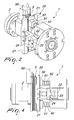
Figure 2 is a perspective view of the device according to the invention; -
Figure 3 is a top plan view of the device according to the invention; -
Figure 4 is a side elevation view of the device according to the invention; -
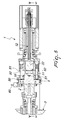
Figure 5 is a sectional view of the device, taken along the line V-V ofFigure 1 ; -
Figure 6 is a sectional view of the device according to the invention, taken along the line VI-VI ofFigure 5 ; -
Figure 7 is a view of the spool taken from its short side; -
Figure 8 is a sectional view of the device, taken along a line which is parallel to its long sides. - With reference to the figures, the device for the cross-winding of wire on spools in general according to the invention, generally designated by the
reference numeral 1, comprises aspindle 2, which is connected to a supportingframe 3 of a winding machine, generally designated by thereference numeral 4. - The
spindle 2 defines means 10 for retaining the core of thespool 5 on which the wire is wound in order to provide a spool with parallel wires on the long sides and crossed wires on the short sides. - The
means 10, in a preferred but not exclusive embodiment, are provided by way of arod 11 that extends in an axial direction with respect to the spool. - A particular feature of the device according to the invention consists in that there is a
clamp 20, which is arranged on the axis of thespool 5 and is supported by amovable frame 30, which can slide in a direction that is parallel to the axis of the clamp or theclamps 20, which can be supported by thecross-member 31 of theframe 30. For translational motion, there aremeans 35 for axial translational motion which are provided, for example, by means of brushless motors that operate on translation joints associated with ball screws, which cause a linear movement. - The clamp is rotatably supported by a sleeve 40 that is connected to said
movable frame 30. - The clamp, which is of a type known per se, is constituted by a pair of mutually
opposite claws 21, which are supported by a supportingblock 22 that defines thetransverse guides 23 in which thecoupling bodies 24 of theclaws 21 can slide, so that such claws can perform a translational motion at right angles to the axis of the spool, by way of means for the translational motion of the pair of claws that can be, for example, constituted by a pneumatic piston. - An
engagement body 50 is slidingly connected to the supportingblock 22 by means ofposts 51 on whichcontrast springs 52 operate and, by means of a seat, is fitted on therod 11, thus providing means for the synchronous rotation of thespindle 2 and of theclamp 20. - The means for synchronous rotation can also be optionally provided in a different manner, such as, for example, by way of motors that rotate synchronously, by way of a connection of the electronic type.
- Above the region affected by the
rod 11, the spindle is provided withpins 60 to which the ends of the wire that provides the electrical winding of the spool are connected. - In practical operation, initially the wire is connected to a pin and then the winding of the first turn is performed on the long side of the core, positioning the wire by means of the clamps that are made to advance, at the axial end of the core, and are moved close together so that the wire is guided so as to be arranged correctly with respect to the core without being able to "bulge", i.e., protrude from the edge of the core.
- Once the first turn has been provided, the
claws 21, which extend substantially parallel with respect to the long side of the core, are opened and moved axially so as to create the space for providing the second turn and are closed when the winding is provided. - This series of operations continues until the first layer of turns is completed.
- At this point, the wire guide 70 that introduces the wire is moved in an axial direction so as to perform the cross-winding of the wire on the short side of the spool and the clamps are made to advance and close again on the first turn provided, performing in succession the operations described earlier, until the other axial end is reached with a new crossing of the wire on the short side.
- During the translational motion of the wire in order to perform the crossing on the short side, the claws in practice retain the wire, allowing to provide the crossing of the wire on the short side and then said claws are made to advance in order to reposition themselves so as to create a constant guide for obtaining turns with a parallel arrangement of the wire on the long sides and crossing on the short sides.
- Once the winding has been completed, for being able to remove the spool provided, the
movable frame 30 is made to slide so that theengagement body 50 moves away from the spindle and the spool can be extracted manually or by way of automatic means. - From what has been described above it is thus evident that the invention achieves the intended aim and objects, and in particular the fact is stressed that a device is provided which makes it possible to automate the provision of a particular winding with wires which are arranged mutually parallel on the long sides and crossed on the short sides.
- It should be noted that the presence of the clamp is particularly important, which clamp with its claws makes it possible to create in each instance the space suitable for inserting the wire, which is always arranged correctly and retained correctly when the crossed portion has to be provided at the short sides.
- The invention thus conceived is susceptible of numerous modifications and variations, all of which are within the scope of the appended claims.
- All the details may further be replaced with other technically equivalent elements.
- In practice, the materials used, as long as they are compatible with the specific use, as well as the contingent shapes and dimensions, may be any according to requirements.
- The disclosures in Italian Patent Application No.
MI2009A000737 - Where technical features mentioned in any claim are followed by reference signs, those reference signs have been included for the sole purpose of increasing the intelligibility of the claims and accordingly, such reference signs do not have any limiting effect on the interpretation of each element identified by way of example by such reference signs.
Claims (7)
- A device for the cross-winding of wire on spools in general, comprising a spindle (2) for supporting a spool (5) which has a pair of mutually opposite long sides joined by a pair of mutually opposite short sides, characterized in that it comprises a clamp (20) which can be arranged on the axis of said spool (5) and is provided with a pair of mutually opposite claws (21), which can engage said spool (5) for positioning, on the long side of said spool, a wire fed by a wire guide (70), means (35) being also provided for the translational motion of said clamp (20) along the axis of said spool (5) and means for the translational motion of said pair of claws (21) along a direction that is substantially perpendicular to said axis, means (11, 50) being also provided for the synchronous rotation of said spindle (2) and of said clamp (20).
- The device according to claim 1, characterized in that it comprises, on said spindle (2), means (11) for the detachable retention of the core of said spool.
- The device according to one or more of the preceding claims, characterized in that said means for the translational motion of said clamp (20) along the axis of said spool (5) comprise a movable frame (30), which defines a cross-member (31) for supporting said clamp, said movable frame (30) being able to perform a translational motion along a direction that is substantially parallel to the axis of said clamp (20).
- The device according to one or more of the preceding claims, characterized in that said means for the synchronous rotation of said spindle (2) and of said clamp (20) comprise a rod (11), which protrudes from said spindle (2) and can engage a seat defined correspondingly on an engagement body (50) that is associated with a supporting block (22) of said clamp (20).
- The device according to one or more of the preceding claims, characterized in that said engagement body (50) is supported slidingly by said supporting block by means of posts (51) on which a contrast spring (52) operates.
- The device according to one or more of the preceding claims, characterized in that said means for the translational motion of said pair of claws (21) along a direction that is substantially perpendicular to said axis comprise transverse guides (23), which slidingly accommodate coupling bodies (24) of said claws (21).
- The device according to one or more of the preceding claims, characterized in that said claws (21) extend substantially parallel to the long side of said spool (5).
Applications Claiming Priority (1)
| Application Number | Priority Date | Filing Date | Title |
|---|---|---|---|
| IT000737A ITMI20090737A1 (en) | 2009-04-30 | 2009-04-30 | DEVICE FOR CROSSING THE WIRE ON ROLLS IN GENERAL. |
Publications (2)
| Publication Number | Publication Date |
|---|---|
| EP2246865A2 true EP2246865A2 (en) | 2010-11-03 |
| EP2246865A3 EP2246865A3 (en) | 2011-03-09 |
Family
ID=41397246
Family Applications (1)
| Application Number | Title | Priority Date | Filing Date |
|---|---|---|---|
| EP10159417A Withdrawn EP2246865A3 (en) | 2009-04-30 | 2010-04-08 | Device for the cross-winding of wire on spools in general |
Country Status (2)
| Country | Link |
|---|---|
| EP (1) | EP2246865A3 (en) |
| IT (1) | ITMI20090737A1 (en) |
Cited By (2)
| Publication number | Priority date | Publication date | Assignee | Title |
|---|---|---|---|---|
| CN103632786A (en) * | 2012-08-24 | 2014-03-12 | 中国北车集团大同电力机车有限责任公司 | A vertical strip winding device |
| ITUB20159353A1 (en) * | 2015-12-22 | 2017-06-22 | Marsilli & Co | SPINDLE WITH QUICK CONNECTION, PARTICULARLY FOR MACHINES FOR THE WINDING OF ELECTRIC ROLLS. |
Families Citing this family (1)
| Publication number | Priority date | Publication date | Assignee | Title |
|---|---|---|---|---|
| CN110364354B (en) * | 2019-08-13 | 2020-12-25 | 广西电网有限责任公司电力科学研究院 | Microelectronic hollow inductance bobbin |
Family Cites Families (1)
| Publication number | Priority date | Publication date | Assignee | Title |
|---|---|---|---|---|
| US20010015393A1 (en) * | 1998-02-24 | 2001-08-23 | Hiroshi Miyazaki | Winding apparatus |
-
2009
- 2009-04-30 IT IT000737A patent/ITMI20090737A1/en unknown
-
2010
- 2010-04-08 EP EP10159417A patent/EP2246865A3/en not_active Withdrawn
Non-Patent Citations (1)
| Title |
|---|
| None |
Cited By (4)
| Publication number | Priority date | Publication date | Assignee | Title |
|---|---|---|---|---|
| CN103632786A (en) * | 2012-08-24 | 2014-03-12 | 中国北车集团大同电力机车有限责任公司 | A vertical strip winding device |
| CN103632786B (en) * | 2012-08-24 | 2016-11-09 | 中车大同电力机车有限公司 | Band vertical-coiling device |
| ITUB20159353A1 (en) * | 2015-12-22 | 2017-06-22 | Marsilli & Co | SPINDLE WITH QUICK CONNECTION, PARTICULARLY FOR MACHINES FOR THE WINDING OF ELECTRIC ROLLS. |
| EP3185264A1 (en) * | 2015-12-22 | 2017-06-28 | Marsilli S.p.A. | Spindle with quick coupling, particularly for machines for winding electric coils |
Also Published As
| Publication number | Publication date |
|---|---|
| EP2246865A3 (en) | 2011-03-09 |
| ITMI20090737A1 (en) | 2010-11-01 |
Similar Documents
| Publication | Publication Date | Title |
|---|---|---|
| CN105645175B (en) | A kind of fully automatic wire winding machine | |
| CN105379082B (en) | Coil installation method and coil installs fixture | |
| US10749418B2 (en) | Methods for forming woven undulated coil assemblies | |
| EP2015427A2 (en) | Winding method and winding device | |
| CN106663995B (en) | Coil manufacturing apparatus and coil manufacturing method | |
| KR102351724B1 (en) | Wire inserting device, elongated workpiece winding apparatus and wire inserting method | |
| EP2246865A2 (en) | Device for the cross-winding of wire on spools in general | |
| CN113611528A (en) | Wire winding and twisting machine for small-hole magnetic ring | |
| EP2447964B1 (en) | Machine for winding toroidal components of electrical machines | |
| CN106712410B (en) | Armature winding flat copper wire end torsion device | |
| JP5054424B2 (en) | Winding method, winding machine and multi-pole armature work | |
| CN204304733U (en) | Coil winding machine | |
| CN215955083U (en) | Wire winding and twisting machine for small-hole magnetic ring | |
| EP3223411A1 (en) | Machine for performing wire windings on cores arranged on the internal lateral surface of cylindrical stators for electric motors | |
| CN204149155U (en) | A magnetic ring manipulator and automatic winding machine | |
| RU2671330C2 (en) | Clamping device | |
| CN203832787U (en) | Annular wire winding double-binding machine | |
| CN211455877U (en) | Electricity core unloader | |
| CN204209033U (en) | Coiling machine and coiling machine subassembly | |
| CN104009597B (en) | Machine is inserted into the coiling that stubborn coil insertion stator is turned round without metal wire | |
| CN202796427U (en) | Remaining wire clamping mechanism of multi-head winding machine | |
| CN117294092B (en) | Magnetic core winding machine | |
| CN203612732U (en) | Automatic winding device | |
| CN210575518U (en) | Inductance coil clamping mechanism | |
| CN101352739B (en) | Edge bending machine and processing method using the equipment |
Legal Events
| Date | Code | Title | Description |
|---|---|---|---|
| PUAI | Public reference made under article 153(3) epc to a published international application that has entered the european phase |
Free format text: ORIGINAL CODE: 0009012 |
|
| AK | Designated contracting states |
Kind code of ref document: A2 Designated state(s): AT BE BG CH CY CZ DE DK EE ES FI FR GB GR HR HU IE IS IT LI LT LU LV MC MK MT NL NO PL PT RO SE SI SK SM TR |
|
| AX | Request for extension of the european patent |
Extension state: AL BA ME RS |
|
| PUAL | Search report despatched |
Free format text: ORIGINAL CODE: 0009013 |
|
| AK | Designated contracting states |
Kind code of ref document: A3 Designated state(s): AT BE BG CH CY CZ DE DK EE ES FI FR GB GR HR HU IE IS IT LI LT LU LV MC MK MT NL NO PL PT RO SE SI SK SM TR |
|
| AX | Request for extension of the european patent |
Extension state: AL BA ME RS |
|
| STAA | Information on the status of an ep patent application or granted ep patent |
Free format text: STATUS: THE APPLICATION IS DEEMED TO BE WITHDRAWN |
|
| 18D | Application deemed to be withdrawn |
Effective date: 20110910 |