EP2246725A2 - Microscope with fixed imaging unit and movable objective lens - Google Patents
Microscope with fixed imaging unit and movable objective lens Download PDFInfo
- Publication number
- EP2246725A2 EP2246725A2 EP10004532A EP10004532A EP2246725A2 EP 2246725 A2 EP2246725 A2 EP 2246725A2 EP 10004532 A EP10004532 A EP 10004532A EP 10004532 A EP10004532 A EP 10004532A EP 2246725 A2 EP2246725 A2 EP 2246725A2
- Authority
- EP
- European Patent Office
- Prior art keywords
- unit
- objective lens
- microscope
- observation
- optical axis
- Prior art date
- Legal status (The legal status is an assumption and is not a legal conclusion. Google has not performed a legal analysis and makes no representation as to the accuracy of the status listed.)
- Withdrawn
Links
Images


Classifications
-
- G—PHYSICS
- G02—OPTICS
- G02B—OPTICAL ELEMENTS, SYSTEMS OR APPARATUS
- G02B21/00—Microscopes
- G02B21/24—Base structure
- G02B21/241—Devices for focusing
-
- G—PHYSICS
- G02—OPTICS
- G02B—OPTICAL ELEMENTS, SYSTEMS OR APPARATUS
- G02B21/00—Microscopes
- G02B21/36—Microscopes arranged for photographic purposes or projection purposes or digital imaging or video purposes including associated control and data processing arrangements
Definitions
- the present invention relates to a microscope that moves an objective lens along an observation optical axis with respect to a specimen.
- the microscope disclosed in Japanese Laid-open Patent Publication No. 2004-348089 and Japanese Laid-open Patent Publication No. 2006-337471 has a problem that when the objective lens and the camera are moved together as a unit, the weight balance becomes unstable, and as a result, it becomes difficult to focus on the specimen. This problem can be solved if the microscope is configured to be tolerant of a significant change in weight balance. However, it leads to a problem that the device configuration is complicated.
- FIG. 1 is a side view illustrating a configuration of a microscope 1 according to a first embodiment of the present invention.
- the microscope 1 has a base unit 20, a stage 30, a supporting unit 40, a rotary holding unit 50, a focusing unit 60, and an imaging unit 70.
- the base unit 20 is a mount part supporting the entire microscope 1.
- the stage 30 is supported by the base unit 20, and has a specimen table 30a on a top surface thereof.
- the specimen table 30a is a table on which a specimen S is put.
- the stage 30 is connected to a stage handle 30b by a moving mechanism (not shown), and makes a rotational movement in an X-Y direction shown the drawing and around an observation optical axis L by the turning operation of the stage handle 30b.
- the L-shaped supporting unit 42 is a member that a right prism is bent into an L shape, and has a body portion 42a joined to the strut unit 41 along the side surface of the strut unit 41 and an arm portion 42b extending from the upper part of the body portion 42a in a horizontal direction.
- the L-shaped supporting unit 42 is joined to the strut unit 41 so that the body portion 42a is along the side surface of the strut unit 41.
- the focusing-unit moving mechanism 43 has a focus handle 43a and a lift mechanism with a pinion and a rack (not shown) to which the focus handle 43a is connected.
- the focusing-unit moving mechanism 43 can move an enclosure 61 to be described below along the body portion 42a.
- the focusing-unit moving mechanism 43 can move the enclosure 61 in a direction parallel to the observation optical axis L.
- the focusing-unit moving mechanism 43 having the lift mechanism with the pinion and the rack is described as an example; however, the configuration of the focusing-unit moving mechanism 43 is not limited to this, and any other configuration can be employed as long as the focusing-unit moving mechanism 43 can move the enclosure 61 in the direction parallel to the observation optical axis L.
- the focusing-unit moving mechanism 43 can have a lift mechanism with a ball screw.
- the illumination light emitted from the light source 63a is concentrated into parallel light by the condenser lens 63c, and focused into a first light source image at the position of the aperture stop 63f by the condenser lens 63d. After that, the illumination light enters the condenser lens 63e via the field stop 63g, and is reflected to the side of the objective lens 62 by the optical-path splitting element 63b, and then falls on the objective lens 62 along the observation optical axis L.
- the illumination light is focused into a second light source image at the back focal position of the objective lens 62, and after the illumination light is concentrated into approximately-parallel light by passing through the objective lens 62, the specimen S is irradiated with the illumination light.
- the reflected light from the specimen S passes, as observation light, through the objective lens 62 and the optical-path splitting element 63b, and enters the imaging lens 70b via the zoom lenses 64a and 64b. Then, an observation image of the specimen S is focused on the imaging element 70c by the imaging lens 70b.
- FIG. 3 is a side view of a microscope 100 according to the first variation of the microscope 1 shown in FIG. 1 .
- a focusing mechanism 110 of the microscope 100 has a motor M for generating power for movement of the enclosure 61.
- the microscope 100 moves the enclosure 61 by driving the motor M.
- a rotation axis is connected to the rotation center of a pinion of the focusing mechanism 110, and the connected rotation axis is rotated by the motor M. Consequently, the operator does not have to perform the focus operation by rotating the focus handle 43a, and thus the burden on the operator can be reduced.
- FIG. 5 is a side view of a microscope 300 according to the third variation of the microscope 1 shown in FIG. 1 .
- a focusing unit 310 of the microscope 300 has a revolving nosepiece 311.
- the revolving nosepiece 311 holds a plurality of objective lenses 62, and sets desired one of the plurality of objective lenses 62 on the observation optical axis L.
- the revolving nosepiece 311 can be added to the focusing unit 310 because the weight balance at the time of movement of the objective lens 62 is stabilized as the objective lens 62 can be moved for focusing with the imaging unit 70 fixed. This makes it possible to easily switch among the objective lenses 62 of different magnifications from one another and set one of them on the observation optical axis L.
- the microscope 540 Since configurations of main parts of the microscope 540 are identical to those of the microscope 501 according to the second embodiment, the microscope 540 produces the same effect as the microscope 501 according to the second embodiment. Furthermore, as the microscope 540 includes the revolving nosepiece 542, an operator can switch to an objective lens to be used without removing a previously- used objective lens to replacing it to the objective lens to be used, so the work burden can be reduced. Other publicly-known means with a bearing can be used as the rotation mechanism of the revolving nosepiece.
Landscapes
- Physics & Mathematics (AREA)
- Chemical & Material Sciences (AREA)
- Analytical Chemistry (AREA)
- General Physics & Mathematics (AREA)
- Optics & Photonics (AREA)
- Engineering & Computer Science (AREA)
- Multimedia (AREA)
- Microscoopes, Condenser (AREA)
Abstract
Description
- The present invention relates to a microscope that moves an objective lens along an observation optical axis with respect to a specimen.
- Conventionally, there is a microscope that makes an observation of a specimen by moving an objective lens along an observation optical axis with respect to the specimen and displaying an observation image on a liquid-crystal monitor or the like. For example, a microscope that makes an observation of a specimen by moving an objective lens and a camera together as a unit is disclosed in Japanese Laid-open Patent Publication No.
2004-348089 2006-337471 - However, the microscope disclosed in Japanese Laid-open Patent Publication No.
2004-348089 2006-337471 - A microscope according to an aspect of the present invention includes an objective lens; an imaging unit that has an imaging lens for forming an observation image of a specimen and an imaging element for taking the observation image, the imaging lens and the imaging element being arranged on an observation optical axis, and the imaging unit being optically connected to the objective lens by a parallel light flux; and a supporting unit that fixedly supports the imaging unit, and movably supports the objective lens.
- The above and other features, advantages and technical and industrial significance of this invention will be better understood by reading the following detailed description of presently preferred embodiments of the invention, when considered in connection with the accompanying drawings.
-
-
FIG. 1 is a side view illustrating a configuration of a microscope according to a first embodiment of the present invention. -
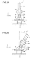
FIG. 2A is a diagram illustrating a state where a supporting unit shown inFIG. 1 stands in an upright position. -
FIG. 2B is a diagram illustrating a state where the supporting unit shown inFIG. 1 is tilted around a horizontal axis line. -
FIG. 3 is a side view of a microscope according to a first variation of the microscope shown inFIG. 1 . -
FIG. 4 is a side view of a microscope according to a second variation of the microscope shown inFIG. 1 . -
FIG. 5 is a side view of a microscope according to a third variation of the microscope shown inFIG. 1 . -
FIG. 6 is an enlarged view of a main portion of a revolving nosepiece shown inFIG. 5 . -
FIG. 7 is a side view illustrating a configuration of a microscope according to a second embodiment of the present invention. -
FIG. 8 is a side view illustrating a case where a focusing unit of the microscope according to the second embodiment is moved on the lower side. -
FIG. 9 is a side view illustrating a configuration of a microscope according to a third embodiment of the present invention. -
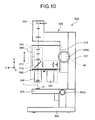
FIG. 10 is a side view illustrating a configuration of a microscope according to a fourth embodiment of the present invention. -
FIG. 11 is a sectional side view of a revolving nosepiece of the microscope according to the fourth embodiment. - Exemplary embodiments of the present invention are explained in detail below with reference to the accompanying drawings. The present invention is not limited to the embodiments.
-
FIG. 1 is a side view illustrating a configuration of amicroscope 1 according to a first embodiment of the present invention. As shown inFIG. 1 , themicroscope 1 has abase unit 20, astage 30, a supportingunit 40, arotary holding unit 50, a focusingunit 60, and animaging unit 70. - The
base unit 20 is a mount part supporting theentire microscope 1. Thestage 30 is supported by thebase unit 20, and has a specimen table 30a on a top surface thereof. The specimen table 30a is a table on which a specimen S is put. Thestage 30 is connected to astage handle 30b by a moving mechanism (not shown), and makes a rotational movement in an X-Y direction shown the drawing and around an observation optical axis L by the turning operation of thestage handle 30b. - The supporting
unit 40 has astrut unit 41, an L-shaped supportingunit 42, and a focusing-unit moving mechanism 43. Thestrut unit 41 is a right prism-like strut, and is rotatably held by thebase unit 20 via therotary holding unit 50 so that thestrut unit 41 can rotate around a horizontal axis line P. Furthermore, thestrut unit 41 is held by thebase unit 20 so that a side surface of which is parallel to a direction of the observation optical axis L. The L-shaped supportingunit 42 is a member that a right prism is bent into an L shape, and has abody portion 42a joined to thestrut unit 41 along the side surface of thestrut unit 41 and anarm portion 42b extending from the upper part of thebody portion 42a in a horizontal direction. The L-shaped supportingunit 42 is joined to thestrut unit 41 so that thebody portion 42a is along the side surface of thestrut unit 41. - The focusing-
unit moving mechanism 43 has afocus handle 43a and a lift mechanism with a pinion and a rack (not shown) to which thefocus handle 43a is connected. By the operation of thefocus handle 43a, the focusing-unit moving mechanism 43 can move anenclosure 61 to be described below along thebody portion 42a. In other words, the focusing-unit moving mechanism 43 can move theenclosure 61 in a direction parallel to the observation optical axis L. The focusing-unit moving mechanism 43 having the lift mechanism with the pinion and the rack is described as an example; however, the configuration of the focusing-unit moving mechanism 43 is not limited to this, and any other configuration can be employed as long as the focusing-unit moving mechanism 43 can move theenclosure 61 in the direction parallel to the observation optical axis L. For example, the focusing-unit moving mechanism 43 can have a lift mechanism with a ball screw. - The
rotary holding unit 50 has arotating mechanism 50a and astrut fixing knob 50b. Thestrut fixing knob 50b is connected to therotating mechanism 50a, for example, via a screw unit (not shown), and fixes thestrut unit 41 at a desired rotational position around the horizontal axis line P. Specifically, therotary holding unit 50 fixes thestrut unit 41 at the desired rotational position with thestrut unit 41 pressed against thebase unit 20 by tightening up thestrut fixing knob 50b, and turns the supportingunit 40 by loosening thestrut fixing knob 50b. Namely, therotary holding unit 50 holds a lower end of the supportingunit 40 or near the lower end so that the supportingunit 40 can turn. - The focusing
unit 60 has theenclosure 61 formed into a box, anobjective lens 62, an epi-illumination projecting unit 63, and amagnification converting unit 64. Theenclosure 61 is movably supported by thebody portion 42a via the focusing-unit moving mechanism 43 so that theenclosure 61 can move in the direction parallel to the observation optical axis L. - The
objective lens 62 is attached to the lower part of theenclosure 61, and moves with respect to the specimen S along the observation optical axis L with movement of theenclosure 61. - The epi-
illumination projecting unit 63 is provided in theenclosure 61, and lets illumination light fall on theobjective lens 62. The epi-illumination projecting unit 63 has alight source 63a, an optical-path splittingelement 63b,condenser lenses aperture stop 63f, and afield stop 63g. - The
light source 63a emits illumination light in a range of wavelengths from a visible region to an ultraviolet region with a white LED or the like. As the optical-path splittingelement 63b, a half mirror, a dichroic mirror, or the like is used. The optical-path splittingelement 63b is arranged on the observation optical axis L between themagnification converting unit 64 and theobjective lens 62, reflects the illumination light emitted from thelight source 63a to the side of theobjective lens 62, and lets the observation light reflected from the specimen S therethrough. - The
condenser lenses light source 63a and the optical-path splittingelement 63b. Thecondenser lens 63c concentrates the illumination light emitted from thelight source 63a into a parallel light. Thecondenser lens 63d focuses the illumination light concentrated into the parallel light by thecondenser lens 63c into a first light source image at the position of theaperture stop 63f. Thecondenser lens 63e focuses the illumination light entering via thefield stop 63g from the first light source image into a second light source image at the back focal position of theobjective lens 62 on a reflection optical path of the optical-path splitting element 63b. The configuration of the epi-illumination projecting unit 63 is not limited to that is described above; any other configuration can be employed as long as the epi-illumination projecting unit 63 lets illumination light fall on theobjective lens 62 so that the specimen S is irradiated with parallel light via theobjective lens 62. - The
magnification converting unit 64 is provided in theenclosure 61, and has twozoom lenses magnification converting unit 64 moves any of thezoom lenses magnification converting unit 64 having two zoom lenses is described as an example; however, the configuration of themagnification converting unit 64 is not limited to this, and any other configuration can be employed as long as themagnification converting unit 64 has at least two zoom lenses and can convert the observation magnification. - The
imaging unit 70 is fixed to thearm portion 42b, and supported by thearm portion 42b. Theimaging unit 70 has atube 70a, animaging lens 70b, and animaging element 70c. Theimaging lens 70b is arranged on the observation optical axis L in thetube 70a, and focuses a parallel light flux from the side of theobjective lens 62 into an observation image of the specimen S. As theimaging element 70c, a CCD camera or the like is used. Theimaging element 70c is arranged on the observation optical axis L in thetube 70a. Theimaging element 70c takes the observation image of the specimen S imaged by theimaging lens 70b, and outputs the observation image of the specimen S to a display unit (not shown), such as a liquid-crystal monitor, provided to the outside via acable 70d or the like so that the observation image of the specimen S is displayed on the display unit. In this manner, theimaging lens 70b and theimaging element 70c are arranged on the observation optical axis L, whereby theimaging unit 70 is optically connected to theobjective lens 62 by the parallel light flux. - In this
microscope 1, the illumination light emitted from thelight source 63a is concentrated into parallel light by thecondenser lens 63c, and focused into a first light source image at the position of theaperture stop 63f by thecondenser lens 63d. After that, the illumination light enters thecondenser lens 63e via thefield stop 63g, and is reflected to the side of theobjective lens 62 by the optical-path splitting element 63b, and then falls on theobjective lens 62 along the observation optical axis L. After that, the illumination light is focused into a second light source image at the back focal position of theobjective lens 62, and after the illumination light is concentrated into approximately-parallel light by passing through theobjective lens 62, the specimen S is irradiated with the illumination light. The reflected light from the specimen S passes, as observation light, through theobjective lens 62 and the optical-path splitting element 63b, and enters theimaging lens 70b via thezoom lenses imaging element 70c by theimaging lens 70b. - Subsequently, how to operate the
microscope 1 according to the first embodiment is explained. First, an operator loosens thestrut fixing knob 50b, and turns the supportingunit 40 to a desired position. After that, the operator fixes the supportingunit 40 by tightening up thestrut fixing knob 50b. As a result, the supportingunit 40 is fixed in an upright state (FIG. 2A ) or a tilted state in which the supportingunit 40 is tilted at a desired angle θ around the horizontal axis line P (FIG. 2B ). After that, the operator puts a specimen S on the specimen table 30a, and moves the specimen S by turning thestage handle 30b to make a rough position (focus) adjustment of theobjective lens 62 with respect to the specimen S. - After that, the operator moves the
enclosure 61 by turning thefocus handle 43a. Namely, the operator focuses themicroscope 1 on the specimen S by moving theobjective lens 62 along the observation optical axis L. At this time, in a state where theimaging unit 70 is fixed to thearm portion 42b, theobjective lens 62 is moved. Furthermore, since the epi-illumination projecting unit 63 is provided in theenclosure 61, the epi-illumination projecting unit 63 moves together with the movement of theobjective lens 62 along the observation optical axis L. - In the
microscope 1 according to the first embodiment, the supportingunit 40 fixedly supports theimaging unit 70 and movably supports theobjective lens 62, so the focusingunit 60 including theobjective lens 62 can be moved for focusing with theimaging unit 70 fixed. At this time, although a positional relation between theimaging unit 70 and theobjective lens 62 varies, theimaging unit 70 is optically connected to theobjective lens 62 by a parallel light flux, so there is no optical impact. Consequently, the weight balance of themicroscope 1 at the time of movement of theobjective lens 62 is stabilized as compared with a case where theobjective lens 62 and theimaging unit 70 are moved together as a unit. Furthermore, even when theobjective lens 62 is moved along the observation optical axis L in a state where the supportingunit 40 is tilted at the angle θ as shown inFIG. 2B , there is little change in the position of the gravity center of themicroscope 1, so the weight balance of themicroscope 1 is stabilized. Consequently, there is no need to employ a device configuration tolerant of a change in weight balance as in the case where theobjective lens 62 and theimaging unit 70 are moved together as a unit, and thus it is possible to construct a microscope apparatus in a simple configuration. - Moreover, in the
microscope 1 according to the first embodiment, the epi-illumination projecting unit 63 moves together with the movement of theobjective lens 62 along the observation optical axis L, so even when theobjective lens 62 is moved, a light source image can be focused at the back focal position of theobjective lens 62. Consequently, it is possible to provide an optimum illumination with respect to the specimen S. - Subsequently, a first variation of the
microscope 1 according to the first embodiment is explained.FIG. 3 is a side view of amicroscope 100 according to the first variation of themicroscope 1 shown inFIG. 1 . In this first variation, a focusingmechanism 110 of themicroscope 100 has a motor M for generating power for movement of theenclosure 61. Themicroscope 100 moves theenclosure 61 by driving the motor M. For example, a rotation axis is connected to the rotation center of a pinion of the focusingmechanism 110, and the connected rotation axis is rotated by the motor M. Consequently, the operator does not have to perform the focus operation by rotating thefocus handle 43a, and thus the burden on the operator can be reduced. - Subsequently, a second variation of the
microscope 1 according to the first embodiment is explained.FIG. 4 is a side view of amicroscope 200 according to the second variation of themicroscope 1 shown inFIG. 1 . In this second variation, animaging unit 210 of themicroscope 200 has an optical-path changing element 210a, such as a total reflection mirror, which changes an optical path of an observation light entering theimaging lens 70b in the horizontal direction. Theimaging lens 70b and theimaging element 70c are arranged on an observation optical axis of the observation light of which the optical path is changed in the horizontal direction by the optical-path changing element 210a. Consequently, the height of the microscope can be reduced, and the gravity center can be kept low; thus, the weight balance at the time of movement of theobjective lens 62 is further stabilized. - Subsequently, a third variation of the
microscope 1 according to the first embodiment is explained.FIG. 5 is a side view of amicroscope 300 according to the third variation of themicroscope 1 shown inFIG. 1 . In this third variation, a focusingunit 310 of themicroscope 300 has a revolvingnosepiece 311. The revolvingnosepiece 311 holds a plurality ofobjective lenses 62, and sets desired one of the plurality ofobjective lenses 62 on the observation optical axis L. In this manner, the revolvingnosepiece 311 can be added to the focusingunit 310 because the weight balance at the time of movement of theobjective lens 62 is stabilized as theobjective lens 62 can be moved for focusing with theimaging unit 70 fixed. This makes it possible to easily switch among theobjective lenses 62 of different magnifications from one another and set one of them on the observation optical axis L. -
FIG. 6 is an enlarged view of a main portion of the revolvingnosepiece 311 shown inFIG. 5 . The revolvingnosepiece 311 has arotary member 311a, arotation axis portion 311b, and aclick mechanism 311c. Therotary member 311a removably holds the plurality ofobjective lenses 62. Therotation axis portion 311b rotatably holds therotary member 311a so that therotary member 311a can rotate around a rotation axis line C. Theclick mechanism 311c assists in positioning and arranging the desiredobjective lens 62 out of theobjective lenses 62 held by therotary member 311a on the observation optical axis L. The revolvingnosepiece 311 sets the desiredobjective lens 62 on the observation optical axis L by rotating therotary member 311a and positioning theclick mechanism 311c. The configuration of the revolvingnosepiece 311 is not limited to that is shown inFIG. 5 , and any other configuration can be employed as long as the revolvingnosepiece 311 can hold a plurality ofobjective lenses 62 and set desired one of the plurality ofobjective lenses 62 on the observation optical axis L. It is preferable that a lightweight revolving nosepiece be used as the revolvingnosepiece 311. - In the first embodiment, it is described that the epi-
illumination projecting unit 63 and themagnification converting unit 64 are provided in theenclosure 61, and theenclosure 61 is movably supported by the supportingunit 40; however, the present invention is not limited to this configuration, and any other configuration can be employed as long as theimaging unit 70 is fixedly supported by the supportingunit 40 and theobjective lens 62 is movably supported by the supportingunit 40. For example, out of the epi-illumination projecting unit 63 and themagnification converting unit 64, only the epi-illumination projecting unit 63 can be provided in theenclosure 61. - Furthermore, in the first embodiment, it is described that the
strut unit 41 is a right prism-like strut, and the L-shaped supportingunit 42 is a member that a right prism is bent into an L shape; the shapes of thestrut unit 41 and the L-shaped supportingunit 42 are not limited thereto, and thestrut unit 41 and the L-shaped supportingunit 42 can have any other shapes as long as theimaging unit 70 is fixedly supported on the observation optical axis L by the supportingunit 40 and theenclosure 61 is movably supported by the supportingunit 40 via the focusing-unit moving mechanism 43 so that theenclosure 61 can move in the direction parallel to the observation optical axis L, i.e., as long as theimaging unit 70 is fixedly supported on the observation optical axis L by the supportingunit 40 and theobjective lens 62 is movably supported by the supportingunit 40 so that theobjective lens 62 can move along the observation optical axis L. - Moreover, in the first embodiment, it is described that the supporting
unit 40 is rotatably held by thebase unit 20 via therotary holding unit 50 so that the supportingunit 40 can rotate around the horizontal axis line P; however, the present invention is not limited to this configuration, and the supportingunit 40 can be fixed to thebase unit 20 in an upright state with the supportingunit 40 prevented from rotating. - Second to fourth embodiments of the microscope according to the present invention are explained in detail below with reference to the drawings. In what follows, the X-axis direction in the drawings denotes a horizontal direction of the microscope, the Y-axis direction in the drawings denotes a front-back direction of the microscope, and the Z-axis direction in the drawings denotes a vertical direction of the microscope.
-
FIGS. 7 and8 show a microscope according to the second embodiment of the present invention.FIG. 7 shows the microscope in a state where a focusing unit is located on the upper side, andFIG. 8 shows the microscope in a state where the focusing unit is moved on the lower side.
Amicroscope 501 has abase unit 502, astage 503, and astrut 507. Thebase unit 502 is a part directly placed in a location on which themicroscope 501 is put, such as on the desk, and is mounting for supporting theentire microscope 501. - The
stage 503 is mounted on top of thebase unit 502, and includes aspecimen putting surface 503a on the top face thereof. On thespecimen putting surface 503a, a specimen A, an object to be observed, is put. Thestage 503 can move in directions of the back and forth and the right and left of themicroscope 501 and rotate around the observation optical axis L by the operation of astage handle 503b mounted on thebase unit 502. - The
strut 507 is provided on the back side face of thestage 503 on top of thebase unit 502 in a standing manner. On the front face of thestrut 507, a focusingsupport unit 506 is mounted. On the front face of the focusingsupport unit 506, a focusingunit 505 is movably mounted so that the focusingunit 505 can move up and down via a focusing-unit moving mechanism 510 with respect to the focusingsupport unit 506. The focusing-unit moving mechanism 510 is a mechanism for moving the focusingunit 505 with respect to the focusingsupport unit 506, and is a publicly-known mechanism, such as a mechanism with a rack and a pinion or a mechanism with a ball screw. In the focusingsupport unit 506, afocus handle 506a for moving the focusingunit 505 is mounted. The focusing-unit moving mechanism 510 can be driven by an electric motor M. On the upper side of the focusingsupport unit 506, anarm 508 is formed to extend from the back face side to the front face side of themicroscope 501 so as to project upward above the focusingunit 505. At a leading end of thearm 508 in a direction of projection, atube 509 formed into a cylinder extending in the vertical direction is mounted. - In the
tube 509, an observingunit 504 is provided. - The focusing
unit 505 has an illuminatingunit 512, amagnification converting unit 513, and anobjective lens 514. Theobjective lens 514 is provided so as to project downward from the focusingunit 505. The illuminatingunit 512 has anillumination light source 521,illumination lenses 522, and an optical-path splitting element 523. Theillumination light source 521 is composed of a white LED, and mounted around the observation optical axis L toward the observation optical axis L. Theillumination light source 521 is supplied with power from a power supply (not shown) housed in the focusingunit 505. The optical-path splitting element 523 is composed of a half mirror, and arranged on the observation optical axis L. The optical-path splitting element 523 reflects light from theillumination light source 521 to the side of the specimen A, and lets the reflected light from the specimen therethrough. Theillumination lenses 522 are mounted between theillumination light source 521 and the optical-path splitting element 523. - The
magnification converting unit 513 includes at least twozoom lenses zoom lenses zoom lenses - The observing
unit 504 has animaging lens 525 and animaging element 526. Theimaging element 526 is composed of a CCD. Theimaging element 526 is connected to acable 527, and an observation image is displayed on a monitor (not shown). The observingunit 504 and the focusingunit 505 are optically connected by a parallel light flux. Namely, the reflected light from the specimen A is concentrated into a parallel light flux when the reflected light exits from the focusingunit 505, and the parallel light flux enters theimaging lens 525 of the observingunit 504. The focusingunit 505 is moved along the observation optical axis L by the focusing-unit moving mechanism 510. The focusingunit 505 is moved independently of the observingunit 504. - On the observation optical axis L, in order from bottom to top, the specimen A, the
objective lens 514, the optical-path splitting element 523, thezoom lenses imaging lens 525, and theimaging element 526 are arranged. The illumination light emitted from theillumination light source 521 is reflected by the optical-path splitting element 523, and turned toward the specimen A, and then falls on the specimen A along the observation optical axis L. After that, the illumination light passes through theobjective lens 514, and is focused and irradiated to the specimen A. The reflected light from the specimen A passes through theobjective lens 514 and the optical-path splitting element 523, and enters theimaging lens 525 via thezoom lenses imaging element 526 by theimaging lens 525. - The focusing operation of the
microscope 501 is explained. A specimen A is put on thestage 503, and a rough focus adjustment is performed by turning thestage handle 503b. A fine focus adjustment is performed by turning thefocus handle 506a to move the focusingunit 505 along the observation optical axis L with respect to the focusingsupport unit 506 as shown inFIGS. 7 and8 . Namely, the focusingunit 505 is moved up and down along the observation optical axis L to adjust so that a focal plane (a front focal position) of theobjective lens 514 is located on the specimen A. Furthermore, the magnification (the observation magnification) of an observation optical system can be changed by moving thezoom lenses magnification converting unit 513 along the observation optical axis L by driving a motor (not shown). - Since the
microscope 501 configured as described above achieves an epi-illumination of the same axis as the observation optical axis L even when the focusingunit 505 is moved for focusing in a direction away from the specimen A, the reflected light from the specimen A reliably enters theobjective lens 514. Namely, a decrease in amount of the reflected light from the specimen A is prevented, and it is possible to observe the specimen properly. Furthermore, in themicroscope 501, since the focusingunit 505 is moved for focusing independently of the observingunit 504, a capability required for the focusing operation can be reduced as compared with a microscope in which a focusing unit and an observing unit move for focusing together as a unit, and thus the burden of the focusing operation on an operator can be reduced. If the focusingunit 505 is moved by an electric motor M, the burden of the focusing operation on the operator can be further reduced, and the operability is improved. -
FIG. 9 is a side view illustrating a microscope according to the third embodiment of the present invention. In what follows, portions identical to those explained in the second embodiment are denoted by the same reference numerals, and the description of the portions is omitted. - A focusing
support unit 531 included in amicroscope 530 according to the third embodiment is, in the same manner as the focusingsupport unit 506 in the second embodiment, mounted on the front face of thestrut 507. The focusingunit 505 is movably mounted on the front face of the focusingsupport unit 531 via the focusing-unit moving mechanism 510 so that the focusingunit 505 can move up and down with respect to the focusingsupport unit 531. On the upper side of the focusingsupport unit 531, anarm 531a is formed to extend from the back face side to the front face side of themicroscope 530 so as to project upward above the focusingunit 505. - In the
microscope 530 according to the third embodiment, an observingunit 532 is included in thearm 531a. The observingunit 532 has an optical-path changing element 533, theimaging lens 525, and theimaging element 526. The optical-path changing element 533 changes an optical path of a parallel light flux, and is provided on the side of a leading end of thearm 531a in a direction of projection. The optical-path changing element 533 is a folding mirror. Theimaging lens 525 is mounted on the back face side of themicroscope 530 than the optical-path changing element 533, and theimaging element 526 is mounted on the back face side of themicroscope 530 than theimaging lens 525. - The optical-
path changing element 533 is arranged on the observation optical axis L, and the reflected light (a parallel light flux) from the specimen A, which has exited the focusingunit 505 and entered the observingunit 532, enters the optical-path changing element 533. The reflected light from the specimen A is reflected by the optical-path changing element 533, enters theimaging lens 525, and is focused into an image on theimaging element 526. In this manner, the observingunit 532 and the focusingunit 505 are optically connected to each other by the parallel light flux. - The focusing
unit 505 is moved along the observation optical axis L by the focusing-unit moving mechanism 510. The focusingunit 505 is moved independently of the observingunit 532. - The focusing operation of the
microscope 530 is performed in the same manner as in the second embodiment. Since configurations of main parts of themicroscope 530 are identical to those of themicroscope 501 according to the second embodiment, themicroscope 530 produces the same effect as themicroscope 501 according to the second embodiment. Furthermore, as themicroscope 530 has the optical-path changing element 533, theimaging element 526 and theimaging lens 525 are mounted to be aligned not in the vertical direction of themicroscope 530 but in the front-back direction of themicroscope 530, so the height of theentire microscope 530 can be reduced. -
FIG. 10 is a side view illustrating a microscope according to the fourth embodiment, andFIG. 11 is an enlarged view of a revolving nosepiece portion of the microscope. In what follows, portions identical to those explained in the second embodiment are denoted by the same reference numerals, and the description of the portions is omitted. - In a
microscope 540 according to the fourth embodiment, a focusingunit 541 includes a revolvingnosepiece 542. - The focusing
unit 541 is movably mounted on the front face of the focusingsupport unit 506 so that the focusingunit 541 can move up and down via the focusing-unit moving mechanism 510 with respect to the focusingsupport unit 506. The focusingunit 541 is moved along the observation optical axis L independently of the observingunit 504 by the focusing-unit moving mechanism 510. The focusing-unit moving mechanism 510 is a publicly-known mechanism, such as a mechanism with a rack and a pinion or a mechanism with a ball screw. The focusingunit 541 has anenclosure 548 formed into a box, and the illuminatingunit 512 and themagnification converting unit 513 are provided in theenclosure 548. Theenclosure 548 has a bottom plate and aside wall 548a standing around the bottom plate. - The revolving
nosepiece 542 includes a supportingbody 543, a revolving-nosepiece rotary member 544, a click mechanism 545, andobjective lenses body 543 is composed of the bottom plate of theenclosure 548, which is formed into a substantially flat plate, and a through-hole 551 is formed on the center part of the supportingbody 543. On the upper part of the through-hole 551, a spot-facedportion 552 is formed. The spot-facedportion 552 is formed so that the upper part of the through-hole 551 is opened wider than the other part and the opening of the through-hole 551 is circumferentially stepped. On the spot-facedportion 552, a ring-shapedfriction reducing member 553 is provided. - The revolving-
nosepiece rotary member 544 is formed into a plate, and a through-hole 555 is formed on the center of the revolving-nosepiece rotary member 544. The revolving-nosepiece rotary member 544 has arotating shaft 554, which is the central axis of rotation of the revolving-nosepiece rotary member 544. Therotating shaft 554 is formed into a rod, and one end of therotating shaft 554 in a length direction is ahead portion 554a, the other end is ascrew portion 554b, and a portion between thehead portion 554a and thescrew portion 554b is abody portion 554c. Thehead portion 554a is formed to be thicker than thebody portion 554c, and thebody portion 554c is formed to be thicker than thescrew portion 554b. Thescrew portion 554b is formed into a screw by screw thread cutting. - The
screw portion 554b is fitted into the through-hole 555 of the revolving-nosepiece rotary member 544. A tip of thescrew portion 554b projects downward from the through-hole 555, a projecting portion of thescrew portion 554b is fastened by anut 556. Therotating shaft 554 is fixed to the revolving-nosepiece rotary member 544 so that the revolving-nosepiece rotary member 544 is held by a circular bottom surface of thebody portion 554c of therotating shaft 554 and thenut 556. - The
body portion 554c of therotating shaft 554 is fitted into the through-hole 551 of the supportingbody 543, and thehead portion 554a projects upward from the supportingbody 543. A circular bottom surface of thehead portion 554a is in contact with the spot-facedportion 552 and supported by the supportingbody 543. - In this manner, the revolving-
nosepiece rotary member 544 is rotatably supported by the supportingbody 543. Theobjective lenses rotating shaft 554, are removably mounted on the revolving-nosepiece rotary member 544 with screws. By rotating the revolving-nosepiece rotary member 544, any of theobjective lenses - The click mechanism 545 is composed of a
leaf spring 545a, abearing 545b, and clickgrooves leaf spring 545a is fixed to the lower part of theside wall 548a, and the other end side is provided with thebearing 545b. Thebearing 545b is formed in a cylindrical shape, and rotatably supported by theleaf spring 545a. Theclick grooves nosepiece rotary member 544, and each formed in the shape of a groove into which thebearing 545b falls. When the revolving-nosepiece rotary member 544 is rotated, the bearing 545b falls into theclick groove 545c or theclick groove 545d, thereby positioning theobjective lenses click groove 545c corresponds to theobjective lens 547, and theclick groove 545d corresponds to theobjective lens 546. Namely, in a case where theobjective lens 546 is used for observation, when theobjective lens 546 is arranged on the observation optical axis L, the bearing 545b falls into theclick groove 545d. On the other hand, in a case where theobjective lens 547 is used for observation, when theobjective lens 547 is arranged on the observation optical axis L, the bearing 545b falls into theclick groove 545c, thereby positioning the objective lens. - The operation for switching between the
objective lenses objective lens 547 in a state where theobjective lens 546 is arranged on the observation optical axis L, theobjective lens 546 is held and slowly rotated around therotating shaft 554 by 180 degrees. As a result, thebearing 545b comes out from theclick groove 545d, and thebearing 545b then falls into theother click groove 545c. In this way, switching between theobjective lenses - Since configurations of main parts of the
microscope 540 are identical to those of themicroscope 501 according to the second embodiment, themicroscope 540 produces the same effect as themicroscope 501 according to the second embodiment. Furthermore, as themicroscope 540 includes the revolvingnosepiece 542, an operator can switch to an objective lens to be used without removing a previously- used objective lens to replacing it to the objective lens to be used, so the work burden can be reduced. Other publicly-known means with a bearing can be used as the rotation mechanism of the revolving nosepiece. - In the second to fourth embodiments described above, the imaging element is mounted as an observing means in the observing unit; alternatively, an eyepiece for making a visual observation can be mounted as the observing means. Furthermore, as the observing means, both the imaging element and the eyepiece can be mounted so as to switch between the monitor observation and the visual observation.
- Additional advantages and modifications will readily occur to those skilled in the art. Therefore, the invention in its broader aspects is not limited to the specific details and representative embodiments shown and described herein. Accordingly, various modifications may be made without departing from the scope of the general inventive concept as defined by the appended claims and their equivalents.
Claims (9)
- A microscope (1; 100; 200; 300; 501; 530; 540) comprising:an objective lens (62; 514; 546; 547);an imaging unit (70; 210; 504; 532) that has an imaging lens (70b; 525) for forming an observation image of a specimen (S; A) and an imaging element (70c; 526) for taking the observation image, the imaging lens (70b; 525) and the imaging element (70c; 526) being arranged on an observation optical axis (L), and the imaging unit (70; 210; 504; 532) being optically connected to the objective lens (62; 514; 546; 547) by a parallel light flux; and
a supporting unit (40; 506, 507; 531, 507) that fixedly supports the imaging unit (70; 210; 504; 532), and movably supports the objective lens (62; 514; 546; 547). - The microscope (1; 100; 200; 300; 501; 530; 540) according to claim 1, further comprising an epi-illumination projecting unit (63; 512) that is supported by the supporting unit (40; 506, 507; 531, 507) with a relative position with respect to the objective lens (62; 514; 546; 547) fixed, moves together with movement of the objective lens (62; 514; 546; 547) along the observation optical axis (L), and lets illumination light fall on the objective lens (62; 514; 546; 547).
- The microscope (1) according to claim 1 or 2, further comprising a rotary holding unit (50) that holds the supporting unit (40) so that the supporting unit (40) can turn around a horizontal axis line.
- The microscope (1; 100; 200; 300; 501; 530; 540) according to claim 2, further comprising:a box-like enclosure (61; 548) that is movably supported by the supporting unit (40; 506, 507; 531, 507); anda magnification converting unit (64; 513) that has at least two zoom lenses (64a, 64b; 524a, 524b) arranged on the observation optical axis (L), and changes the observation magnification by moving any of the zoom lenses (64a, 64b; 524a, 524b) along the observation optical axis (L), whereinthe epi-illumination projecting unit (63; 512) and the magnification converting unit (64; 513) are provided within the enclosure (61; 548),the objective lens (62; 514; 546; 547) is mounted on the lower part of the enclosure (61; 548), andthe objective lens (62; 514; 546; 547) moves along the observation optical axis (L) with movement of the enclosure (61; 548).
- The microscope (1; 100; 200; 300; 501; 530; 540) according to claim 4, wherein
the epi-illumination projecting unit (63; 512) reflects the illumination light to the side of the objective lens (62; 514; 546; 547), and has an optical-path splitting element (63b; 523) that lets observation light reflected from the specimen (S; A) therethrough, and
the optical-path splitting element (63b; 523) is arranged on the observation optical axis (L) between the magnification converting unit (64; 513) and the objective lens (62; 514; 546; 547). - The microscope (100; 501; 530; 540) according to claim 4 or 5, further comprising a motor (M) for generating power for movement of the enclosure (61; 548).
- The microscope (200; 530) according to any one of claims 1 to 6, wherein
the imaging unit (70; 210; 504; 532) has an optical-path changing element (210a; 533) that changes an optical path of an observation light reflected from the specimen (S; A) in a horizontal direction, and
the imaging lens (70b; 525) and the imaging element (70c; 526) are arranged on an observation optical axis (L) of the observation light of which the optical path is changed by the optical-path changing element (210a; 533). - The microscope (300; 540) according to any one of claims 1 to 7, further comprising a revolving nosepiece (311; 542) that holds a plurality of objective lenses (62; 546; 547), and sets a desired objective lens (62; 546; 547) out of the plurality of objective lenses (62; 546; 547) on the observation optical axis (L), wherein
the objective lens (62; 546; 547) optically connected to the imaging unit (70; 504) is the objective lens (62; 546; 547) set on the observation optical axis (L) by the revolving nosepiece (311; 542). - The microscope (1) according to claim 3, wherein the rotary holding unit (50) holds a lower end of the supporting unit (40) or near the lower end so that the supporting unit (40) can turn.
Applications Claiming Priority (2)
| Application Number | Priority Date | Filing Date | Title |
|---|---|---|---|
| JP2009111399A JP2010262071A (en) | 2009-04-30 | 2009-04-30 | Microscope |
| JP2009151475A JP2011008032A (en) | 2009-06-25 | 2009-06-25 | Microscope |
Publications (2)
| Publication Number | Publication Date |
|---|---|
| EP2246725A2 true EP2246725A2 (en) | 2010-11-03 |
| EP2246725A3 EP2246725A3 (en) | 2011-01-26 |
Family
ID=42340836
Family Applications (1)
| Application Number | Title | Priority Date | Filing Date |
|---|---|---|---|
| EP10004532A Withdrawn EP2246725A3 (en) | 2009-04-30 | 2010-04-29 | Microscope with fixed imaging unit and movable objective lens |
Country Status (2)
| Country | Link |
|---|---|
| US (1) | US8289383B2 (en) |
| EP (1) | EP2246725A3 (en) |
Families Citing this family (5)
| Publication number | Priority date | Publication date | Assignee | Title |
|---|---|---|---|---|
| EP2587313B1 (en) * | 2011-10-20 | 2016-05-11 | Samsung Electronics Co., Ltd | Optical measurement system and method for measuring critical dimension of nanostructure |
| JP5969808B2 (en) * | 2012-04-27 | 2016-08-17 | オリンパス株式会社 | Microscope equipment |
| WO2014071390A1 (en) * | 2012-11-05 | 2014-05-08 | Inscopix, Inc. | Miniaturized imaging devices, systems and methods |
| DE102016111949B4 (en) * | 2016-06-30 | 2018-03-01 | Leica Microsystems Cms Gmbh | Laser Microscope System |
| CA3224439A1 (en) * | 2021-07-02 | 2023-01-05 | Zhongwei SHEN | An angled illumination system for microfluidic devices |
Citations (2)
| Publication number | Priority date | Publication date | Assignee | Title |
|---|---|---|---|---|
| JP2004348089A (en) | 2003-05-26 | 2004-12-09 | Olympus Corp | Microscope |
| JP2006337471A (en) | 2005-05-31 | 2006-12-14 | Keyence Corp | Support device and microscope having the same |
Family Cites Families (17)
| Publication number | Priority date | Publication date | Assignee | Title |
|---|---|---|---|---|
| US4210384A (en) * | 1976-09-11 | 1980-07-01 | Carl Zeiss-Stiftung | Inverted-design optical microscope |
| US4855823A (en) * | 1988-05-05 | 1989-08-08 | Applied Engineering Products Co. | Imaging assembly and mounting for surveillance viewing under remote control |
| US4901146A (en) * | 1988-05-05 | 1990-02-13 | Applied Engineering Products Co. | Imaging assembly and mounting for surveillance viewing under remote control |
| US6099522A (en) * | 1989-02-06 | 2000-08-08 | Visx Inc. | Automated laser workstation for high precision surgical and industrial interventions |
| JP2925647B2 (en) * | 1990-04-16 | 1999-07-28 | オリンパス光学工業株式会社 | Microscope magnification changer |
| US5434703A (en) * | 1991-10-09 | 1995-07-18 | Fuji Photo Optical Co., Ltd. | Binocular stereomicroscope |
| US5266791A (en) * | 1991-10-17 | 1993-11-30 | Fuji Photo Optical Co., Ltd. | Autofocus binocular stereomicroscope |
| US5689339A (en) * | 1991-10-23 | 1997-11-18 | Nikon Corporation | Alignment apparatus |
| US5668660A (en) * | 1994-11-29 | 1997-09-16 | Hunt; Gary D. | Microscope with plural zoom lens assemblies in series |
| JP4084061B2 (en) * | 2002-03-18 | 2008-04-30 | 独立行政法人科学技術振興機構 | High stability optical microscope |
| US6995901B2 (en) * | 2004-01-15 | 2006-02-07 | Alpha Innotech Corporation | Optical analysis systems |
| US6853454B1 (en) * | 2004-01-15 | 2005-02-08 | Alpha Innotech Corporation | Optical analysis systems |
| US20050157299A1 (en) * | 2004-01-15 | 2005-07-21 | Heffelfinger David M. | Optical analysis systems |
| JP4558366B2 (en) * | 2004-03-30 | 2010-10-06 | オリンパス株式会社 | System microscope |
| JP5289768B2 (en) * | 2005-09-29 | 2013-09-11 | オリンパス株式会社 | Focus position determination method, focus position determination apparatus, faint light detection apparatus, and faint light detection method |
| WO2007139201A1 (en) * | 2006-05-31 | 2007-12-06 | Olympus Corporation | Organism specimen imaging method and organism specimen imaging device |
| JP5047669B2 (en) * | 2007-04-04 | 2012-10-10 | オリンパス株式会社 | Scanning confocal microscope |
-
2010
- 2010-04-29 EP EP10004532A patent/EP2246725A3/en not_active Withdrawn
- 2010-04-30 US US12/771,021 patent/US8289383B2/en not_active Expired - Fee Related
Patent Citations (2)
| Publication number | Priority date | Publication date | Assignee | Title |
|---|---|---|---|---|
| JP2004348089A (en) | 2003-05-26 | 2004-12-09 | Olympus Corp | Microscope |
| JP2006337471A (en) | 2005-05-31 | 2006-12-14 | Keyence Corp | Support device and microscope having the same |
Also Published As
| Publication number | Publication date |
|---|---|
| EP2246725A3 (en) | 2011-01-26 |
| US8289383B2 (en) | 2012-10-16 |
| US20100277581A1 (en) | 2010-11-04 |
Similar Documents
| Publication | Publication Date | Title |
|---|---|---|
| US6226118B1 (en) | Optical microscope | |
| US5818637A (en) | Computerized video microscopy system | |
| EP2246725A2 (en) | Microscope with fixed imaging unit and movable objective lens | |
| US6400395B1 (en) | Computerized video microscopy system | |
| JPWO2009031477A1 (en) | Autofocus device and microscope | |
| JP2003185929A (en) | Stereomicroscope | |
| JP2017076095A (en) | microscope | |
| EP1586930B1 (en) | System microscope | |
| JP2009282198A (en) | Microscope device | |
| JPH10339845A (en) | Monitor observation type microscope | |
| US6396532B1 (en) | Computer controlled video microscopy system | |
| JP7025530B2 (en) | Dynamic focus zoom system for wide-area confocal and multiphoton microscopy | |
| JP2011027906A (en) | Microscope | |
| JP4653292B2 (en) | System microscope | |
| JP3877380B2 (en) | Optical microscope | |
| JP2011118069A (en) | Microscope illumination device and microscope | |
| JP2011112880A (en) | Microscope | |
| JP6978592B2 (en) | Dynamic focus zoom system for wide-area confocal and multiphoton microscopy | |
| JP2010262071A (en) | Microscope | |
| JPH11183805A (en) | Microscope for operation | |
| JP2011008032A (en) | Microscope | |
| JP2009116054A (en) | Optical device and microscope | |
| JPH10282430A (en) | Inverted microscope | |
| JP2015127775A (en) | Magnifying observation device | |
| JP2018120057A (en) | Imaging device |
Legal Events
| Date | Code | Title | Description |
|---|---|---|---|
| PUAI | Public reference made under article 153(3) epc to a published international application that has entered the european phase |
Free format text: ORIGINAL CODE: 0009012 |
|
| AK | Designated contracting states |
Kind code of ref document: A2 Designated state(s): AT BE BG CH CY CZ DE DK EE ES FI FR GB GR HR HU IE IS IT LI LT LU LV MC MK MT NL NO PL PT RO SE SI SK SM TR |
|
| AX | Request for extension of the european patent |
Extension state: AL BA ME RS |
|
| PUAL | Search report despatched |
Free format text: ORIGINAL CODE: 0009013 |
|
| AK | Designated contracting states |
Kind code of ref document: A3 Designated state(s): AT BE BG CH CY CZ DE DK EE ES FI FR GB GR HR HU IE IS IT LI LT LU LV MC MK MT NL NO PL PT RO SE SI SK SM TR |
|
| AX | Request for extension of the european patent |
Extension state: AL BA ME RS |
|
| 17P | Request for examination filed |
Effective date: 20110427 |
|
| STAA | Information on the status of an ep patent application or granted ep patent |
Free format text: STATUS: THE APPLICATION HAS BEEN WITHDRAWN |
|
| 18W | Application withdrawn |
Effective date: 20130218 |