US4901146A - Imaging assembly and mounting for surveillance viewing under remote control - Google Patents
Imaging assembly and mounting for surveillance viewing under remote control Download PDFInfo
- Publication number
- US4901146A US4901146A US07/378,166 US37816689A US4901146A US 4901146 A US4901146 A US 4901146A US 37816689 A US37816689 A US 37816689A US 4901146 A US4901146 A US 4901146A
- Authority
- US
- United States
- Prior art keywords
- imaging assembly
- objective lens
- mount
- mounting
- lenses
- Prior art date
- Legal status (The legal status is an assumption and is not a legal conclusion. Google has not performed a legal analysis and makes no representation as to the accuracy of the status listed.)
- Expired - Fee Related
Links
Images


Classifications
-
- G—PHYSICS
- G08—SIGNALLING
- G08B—SIGNALLING OR CALLING SYSTEMS; ORDER TELEGRAPHS; ALARM SYSTEMS
- G08B13/00—Burglar, theft or intruder alarms
- G08B13/18—Actuation by interference with heat, light, or radiation of shorter wavelength; Actuation by intruding sources of heat, light, or radiation of shorter wavelength
- G08B13/189—Actuation by interference with heat, light, or radiation of shorter wavelength; Actuation by intruding sources of heat, light, or radiation of shorter wavelength using passive radiation detection systems
- G08B13/194—Actuation by interference with heat, light, or radiation of shorter wavelength; Actuation by intruding sources of heat, light, or radiation of shorter wavelength using passive radiation detection systems using image scanning and comparing systems
- G08B13/196—Actuation by interference with heat, light, or radiation of shorter wavelength; Actuation by intruding sources of heat, light, or radiation of shorter wavelength using passive radiation detection systems using image scanning and comparing systems using television cameras
- G08B13/19617—Surveillance camera constructional details
- G08B13/19632—Camera support structures, e.g. attachment means, poles
-
- G—PHYSICS
- G08—SIGNALLING
- G08B—SIGNALLING OR CALLING SYSTEMS; ORDER TELEGRAPHS; ALARM SYSTEMS
- G08B13/00—Burglar, theft or intruder alarms
- G08B13/18—Actuation by interference with heat, light, or radiation of shorter wavelength; Actuation by intruding sources of heat, light, or radiation of shorter wavelength
- G08B13/189—Actuation by interference with heat, light, or radiation of shorter wavelength; Actuation by intruding sources of heat, light, or radiation of shorter wavelength using passive radiation detection systems
- G08B13/194—Actuation by interference with heat, light, or radiation of shorter wavelength; Actuation by intruding sources of heat, light, or radiation of shorter wavelength using passive radiation detection systems using image scanning and comparing systems
- G08B13/196—Actuation by interference with heat, light, or radiation of shorter wavelength; Actuation by intruding sources of heat, light, or radiation of shorter wavelength using passive radiation detection systems using image scanning and comparing systems using television cameras
- G08B13/19617—Surveillance camera constructional details
- G08B13/19626—Surveillance camera constructional details optical details, e.g. lenses, mirrors or multiple lenses
-
- G—PHYSICS
- G08—SIGNALLING
- G08B—SIGNALLING OR CALLING SYSTEMS; ORDER TELEGRAPHS; ALARM SYSTEMS
- G08B13/00—Burglar, theft or intruder alarms
- G08B13/18—Actuation by interference with heat, light, or radiation of shorter wavelength; Actuation by intruding sources of heat, light, or radiation of shorter wavelength
- G08B13/189—Actuation by interference with heat, light, or radiation of shorter wavelength; Actuation by intruding sources of heat, light, or radiation of shorter wavelength using passive radiation detection systems
- G08B13/194—Actuation by interference with heat, light, or radiation of shorter wavelength; Actuation by intruding sources of heat, light, or radiation of shorter wavelength using passive radiation detection systems using image scanning and comparing systems
- G08B13/196—Actuation by interference with heat, light, or radiation of shorter wavelength; Actuation by intruding sources of heat, light, or radiation of shorter wavelength using passive radiation detection systems using image scanning and comparing systems using television cameras
- G08B13/19617—Surveillance camera constructional details
- G08B13/1963—Arrangements allowing camera rotation to change view, e.g. pivoting camera, pan-tilt and zoom [PTZ]
-
- H—ELECTRICITY
- H04—ELECTRIC COMMUNICATION TECHNIQUE
- H04N—PICTORIAL COMMUNICATION, e.g. TELEVISION
- H04N7/00—Television systems
- H04N7/18—Closed-circuit television [CCTV] systems, i.e. systems in which the video signal is not broadcast
- H04N7/183—Closed-circuit television [CCTV] systems, i.e. systems in which the video signal is not broadcast for receiving images from a single remote source
-
- Y—GENERAL TAGGING OF NEW TECHNOLOGICAL DEVELOPMENTS; GENERAL TAGGING OF CROSS-SECTIONAL TECHNOLOGIES SPANNING OVER SEVERAL SECTIONS OF THE IPC; TECHNICAL SUBJECTS COVERED BY FORMER USPC CROSS-REFERENCE ART COLLECTIONS [XRACs] AND DIGESTS
- Y10—TECHNICAL SUBJECTS COVERED BY FORMER USPC
- Y10T—TECHNICAL SUBJECTS COVERED BY FORMER US CLASSIFICATION
- Y10T74/00—Machine element or mechanism
- Y10T74/20—Control lever and linkage systems
- Y10T74/20207—Multiple controlling elements for single controlled element
Definitions
- the invention is in the field of remotely and robotically controlled television cameras, including lens systems and mountings therefor, especially as adapted for covert, surveillance purposes.
- Motorized surveillance television cameras including those utilizing electronic damaging devices, usually hang into the dome of a dome fixture from a mounting in a ceiling of an area to be watched.
- these cameras and their mountings are very heavy and require special supporting structure other than the ceiling itself.
- the viewing domes of these fixtures be of large diameter (typically twelve inches or larger) to provide adequate viewing of areas to be watched. These domes protrude deeply into the areas to be watched and are conspicuous and unsightly.
- a principal purpose in the making of the invention was to provide a fully integrated, robotic, imaging assembly and mounting therefor for positioning behind a small and inconspicuous viewing dome, with the objective lens of an optical lens arrangement projecting into the dome and mounted for wide sweep tilting and panning viewing movement relative to such dome, which is of minimum width (typically five inches in diameter or less) and depth (typically one and three-quarters inches or less) that minimizes protrusion into the viewing area.
- a feature of the invention in accomplishing this purpose is the positioning of the objective lens of the optical lens arrangement in a mount therefor and the pivoting of such mount, for tilting and panning movement, rearwardly of but adjacent to the objective lens in mounting means that supports the imaging assembly.
- Another purpose was to provide such an assembly and mounting of very light weight (typically ten pounds or less) that can rest on a tile or grill of an acoustical ceiling provided with one or more viewing dome fixtures, and that can easily be moved from one dome fixture to another.
- very light weight typically ten pounds or less
- a further purpose was to provide simple but effective mechanical mounting means for the objective lens and for the entire imaging assembly, including remotely controlled electric motors, limit switches, and parking brakes for tilting and panning movements, whereby any light reflection through the dome fixture would be minimized, if not eliminated altogether, without resorting to the usual practice of placing double domes in the dome fixture.
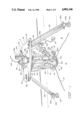
- FIG. 1 represents a pictorial view of an integrated imaging assembly supported in accordance with the invention for remotely controlled, surveillance purposes above the ceiling of an area to be watched through a relatively small and inconspicuous dome fixture in such ceiling, the ceiling and dome fixture being shown in vertical section and the integrated imaging assembly being shown at one of the wide angle scanning positions through which it is adapted to sweep;
- FIG. 2 a top plan view of the embodiment of FIG. 1;
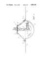
- FIG. 3 a schematic representation of the surveillance viewing area covered by the sweep of the imaging assembly of the invention.
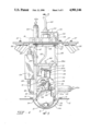
- FIG. 4 a vertical section taken on the line 4--4 of FIG. 2, viewed apart from the ceiling and dome fixture;
- FIG. 5 a vertical axial section taken on the line 5--5 of FIG. 4;
- FIG. 6, a horizontal section taken on the line 6--6 of FIG. 5;
- FIG. 7 a vertical section taken on the line 7--7 of FIG. 5, the barrel and lenses of the lens system being indicated schematically and in non-zoom positions;
- FIG. 8 a view partly in elevation with portions broken away for convenience of illustration and partly in axial vertical section of another embodiment of the invention requiring a somewhat larger dome fixture.
- the invention comprises a fully integrated, electronic, imaging assembly, indicated generally 10, supported by mounting structure, indicated generally 11, placed on the ceiling 12 (shown somewhat schematically) of an area 13, see particularly FIG. 3, such as a merchandise display and sales area, to be watched by combined panning and tilting movement of such imaging assembly 10 for possible shop-lifting or other improper activities.
- the imaging assembly 10 is miniaturized, so as to be unusually small and lightweight and supportable by readily portable mounting structure resting directly on typical ceiling structure such as a tile or grill of an acoustical ceiling, and so as to accomplish its surveillance function through the concave dome 14a of an unusually small dome fixture 14 in ceiling 12.
- imaging assembly 10 includes a high resolution, light sensitive, charge-coupled, electronic image-acquisition device 15a, that is protectively mounted along with customary electronic circuitry in a box 15.
- electronic image-acquisition device 15a is readily obtainable on the open market as a printed circuit chip, e.g. produced in Japan by Fujitsu, Sony, or Hitachi, and produced in the U.S. by R.C.A. or Texas Instruments.
- Imaging assembly 10 also includes an arrangement of lenses, FIGS. 5 and 7, unique to video surveillance cameras but used heretofore in microscopes, which provides for desired miniaturization of the assembly.
- This lens arrangement as here employed comprises a uniquely-mounted objective, i.e. focusing, lens 16 that is small with minimal tell-tale light reflectivity, and a pair of zoom lenses 17a and 17b between fixed lenses 18a and 18b and 19a and 19b.
- the zoom lenses are conventionally mounted, as shown generally at 20, with camming pins and guide slots for back and forth relative movement away from and toward each other, respectively, as they are moved simultaneously forwardly or backwardly.
- a standard video surveillance camera has an objective lens that is at least one and a half inches in diameter, while the microscope lens system of the present invention is about one-half that size or less.
- objective lens 16 is positioned in a spherical mount 21 in a slidable tube 22 for focusing movement back and forth along an axis of the sphere within a passage of the spherical mount coincident with such axis.
- Spherical mount 21 is rigidly interconnected with box 15 by a barrel housing 23 in which zoom lenses 17a and 17b and fixed lenses 18 and 19 are mounted, so that image-acquisition device 15a is in optical alignment with the lens system.
- Optical alignment means only that device 15a is positioned to receive imaged transmitted by the lens system, which may be of any suitable geometric configuration, even to the extent of incorporating one or more mirrors as do some optical configurations known to the art.
- imaging assembly 10 So as to be capable of both panning and tilting movement relative to dome 14a of dome fixture 14, with maximum sweep over an area to be watched, imaging assembly 10 has the spherical mount 21 for objective lens 16 pivoted diametrically of the sphere between a pair of arms 24 and 25, respectively, that depend from a turntable 26, FIG. 5, supported by a platform 27 of mounting structure 11. The arms are held firmly in position relative to each other by a crossbrace 26a.
- imaging assembly 10 can be placed above ceiling 12 so that objective lens 16 extends deeply into the concavity of a five inch diameter dome, and, with say a one and three-quarter inch maximum depth for such concavity of the dome, such objective lens 16 can sweep over a considerably larger viewing area, see 13 of FIG. 3, than can corresponding video cameras of the prior art mounted relative to much larger viewing domes.
- imaging assembly 10 can be tilted as desired under either manual or automatic robotic control from a remote position in the usual closed circuit television system (not shown) of which the device of the invention becomes a part, the body of such spherical mount is cut away or notched, as at 21a, to accommodate a sector gear 28, FIG. 4, and an arrangement for moving objective lens tube 22 up and down, see FIG. 5.
- Such gear 28 is securely fastened to spherical mount 21, as by screws 30, FIG. 1.
- a drive pinion 31 is affixed to the output shaft 32, FIG. 4, of a remotely controlled, miniature, reversible, electric motor 33, and is in mesh with sector gear 28 for rotating the spherical mount back and forth, depending upon the direction of rotation of motor 33, on stub shafts 34 that project into and are journaled in corresponding receiving openings, respectively, of arms 24 and 25 of mounting structure 11. Accordingly, tilting of imaging assembly 10 is controlled by electric motor 33.
- the arrangement for moving objective lens tube 22 up and down comprises a bar 36, FIG. 5, fastened to objective lens tube 22 as by a screw 37, and into which bar the lower threaded end 38a of an output shaft 38 of a remotely controlled, miniature, reversible, electric motor 39 is threaded.
- objective lens 16 is moved either up or down relative to spherical mount 21.
- Panning of imaging assembly 10 and its objective lens 16 relative to dome fixture 14 is carried out through turntable 26 by remotely controlled, miniature, electric motor 44.
- the output shaft of such motor carries a drive pinion 45, FIG. 4, intermeshing with a spur gear 46 affixed to turntable 26 below platform 27.
- Arms 24 and 25 depend from securement at their upper ends to turntable 26, as by means of screws 47 the turntable is rotatably supported by platform 27 by means of a stepped shaft 48, see particularly FIG. 5, passing through the platform and having a portion of reduced diameter journaled in a bearing 49 that is press fit into a housing 50 on the platform.
- a nut 51 on shaft 48 beyond housing 50 maintains turntable 26 in place.
- a passage 52 through turntable 26 and its shaft 48 provides for the running therethrough of a composite electrical cable 53 from the lower, rotor end of a slip ring device 54 of well-known construction that permits repeated, full circle rotation of imaging assembly 10.
- Slip ring device 54 is held in place by a bracket 55.
- Bearing housing 50 is provided with a clamping arm 50a for holding electric motor 44 is place.
- Mounting structure 11 comprises means for removably supporting platform 27 and its associated imaging assembly 10 on and above a ceiling, such as 12, however constructed, but usually one made up of acoustical tiles and lightweight runners on which they rest so that imaging assembly 10 can be readily moved from one dome fixture to another as found expedient from time to time.
- a dome fixture 14 may be inset into one of the acoustic tiles or, preferably, into a grill of relatively thin material customarily present.
- the support means preferably comprises a tripod arrangement adjustably fastened to platform 27.
- three tripod legs indicated 56, respectively, are fastened, as by means of bolts 57, to platform corners in adjustment slots 58. They are each height adjustable, as by means of a foot pad 59 having a stem 59a threaded into the bottom member 56a of the corresponding tripod leg.
- respective limit switches are provided at the terminal locations for activation by appropriate members (not shown) extending from imaging assembly 10.
- power-off brake mechanisms 61 and 62 of well-known type, e.g. units manufactured by Inertia Dynamics, Florida, are provided for activation coincidentally with shut-off of power to the respective electric motors.
- Imaging assembly 10 and its mounting 11 are electrically interconnected with a standard type of receiver, control, and decoder box (not shown) of the previously mentioned closed circuit television system by a plug-in composite cable 63, FIG. 1, for supply of power, for transmission of control signals from the console of such television system, if manually operated, or from suitable circuitry if automatically operated, and for return to such television system of electronically processed video signals derived by image-acquisition device 15a, through respective electrical conductors of such cable.
- Cable 63 connects into the upper, stator end of slip ring device 54 and its respective conductors connect electrically with corresponding conductors of cable 53.
- Electrical cable 53 supplies the electronic circuitry (not shown) in an electronic processing box 64 with power and control signals through respective conductors, while respective conductors 65a of a second electrical cable 65, FIG. 4, carry power and electronically processed control signals to the several electric motors 33, 38, 42, and 44.
- An electrical cable 66 connects image-acquisition device 15a with the electronic camera circuitry in box 64, while respective conductors in cables 53 and 63 carry processed video signals back to the receiver, control, and decoder box of the television system.
- miniaturization of the imaging assembly of the invention is made possible by combining a known image-acquisition device, that has been previously used to a limited extend in video cameras of surveillance systems, with previously known microscope technology modified by suitably regrinding lenses of the lens system as dictated by the new use, modifications that are within the skill of a video optics technician.
- a spherical mount for the objective lens also provides a surface that minimizes tell-tale light reflection through the dome.
- FIG. 8 has an imaging assembly 70 that is structurally and functionally similar to that of the aforedescribed embodiment but is arranged for mounting relative to a somewhat larger viewing dome fixture, here designated 71, so such imaging assembly can be fitted partially or entirely within the concavity of the viewing dome 71a.
- imaging assembly 70 has an objective lens 72 corresponding to lens 16 and positioned in a spherical mount 73 corresponding to mount 21. As here shown, such mount 73 is pivoted between a pair of arms 74 depending form a turntable 75 corresponding to turntable 26 and here supported by tripod legs 76 corresponding to the legs 56.
- Imaging assembly 70 is here shown as positioned entirely within the concavity of viewing dome 71a, which is of greater diameter than is dome fixture 14, e.g. eight inches rather than the more desirable five inches, but still significantly less than the usual twelve inches of customary surveillance systems.
- the entire imaging assembly 70 undergoes panning and tilting movements within the concavity of viewing dome 71a in accomplishing the surveillance required.
- This embodiment of the invention wherein the imaging assembly 70 is wholly within the concavity of viewing dome 71a may be satisfactory for some installations in which maximum inconspicuousness is not required. It is still supported by mounting structure 77, corresponding to the mounting structure 11 of the previously described embodiment, or by other mounting means supported on and by the ceiling 78 or other concealing structural expanse behind which such mounting means is positioned substantially wholly outside the concavity of the viewing dome 71a, and it is still independent of and unattached to the viewing dome.
- Positioning of imaging assembly 70 in this way may be accomplished, as illustrated, by retraction of foot pads 79 (which correspond to the foot pads 59 of the previously described embodiment) relative to the tripod legs 76, or by lengthening the arms 74 (which correspond to the arms 24 and 25 of the previous embodiment) so as to depend more deeply into the concavity of the viewing dome somewhat below the level of the opening of the concavity of such dome.
Abstract
Description
______________________________________
Angular Travel:
             Pan-continuous
             Tilt-0 to 80 deg.
Speed:       Pan-80 deg./sec
             Tilt-30 deg./sec
Braking and Parking:
             +.5 deg.
Environmental:
             Indoor-Outdoor Dome Fixtures
Optical Specifications:
Imager:      2/3" Interline transfer CCD
             Pixel-510(H) × 492(V) high
             resolution Imager
Scanning:    525 lines, 60 Hz, interlace
Video Output:
             1.0 V p-p, Sync Negative, 75 ohm
Minimum Illumination:
             2.0 Lux at F = 1.4
TV Line Resolution:
             370 H, 250 V
AGC, Gamma:  AGC ON, GAMMA = 0.45
External Sync:
             accepts VD, HC sync.
Lens:        Focal Length-12 mm to 76 mm
             Field of View
             Hi Mag 4.6 deg. × 6.2 deg.
             Lo Mag 30 deg.
Zoom Assembly:
             7.5 to 1 zoom power
Weight:      Approx. 10 Lbs
Input Voltage:
             115 VAC, 60 Hz
Power Consumption:
             Transmitter-2.5 VA
             Receiver-115 VAC; 5 VA
             Pan/Tilt Supply-115 VAC
             140 VA Max.; 6 VDC: 50 VA
             Lens supply-0-4 VA Max
             Camera supply-15 VA
Control Method:
             15-pulse train (pulse
             width modulated) super-
             imposed on the video signal
             during the vertical interval
             by the Control Transmitter.
             Pulse train occupies 1 TV
             line period.
Pulse Amplitude:
             Approx. 1 V p-p added to video
             signal, 333 KHZ nom.
Connectors:  Control Transmitter-3 BNC
             connectors.
             Receiver-Video input and out-
             put BNC.
             Control output, AMP Series CPC.
Input Video Level:
             1 V p-p nominal; 2 V p-p at less
             than 75% APL; 1.5 V p-p max at 90%
             APL
System Bandwidth:
             Less than 2db down at 10 MHZ
Power Cord:  3-wire grounded No. 18 AWG,
             TRA/REC
Ambient Temp:
             -40 DEG. F. to + 140 DEG. F.
______________________________________
Claims (34)
Priority Applications (1)
| Application Number | Priority Date | Filing Date | Title |
|---|---|---|---|
| US07/378,166 US4901146A (en) | 1988-05-05 | 1989-07-11 | Imaging assembly and mounting for surveillance viewing under remote control |
Applications Claiming Priority (2)
| Application Number | Priority Date | Filing Date | Title |
|---|---|---|---|
| US07/190,365 US4855823A (en) | 1988-05-05 | 1988-05-05 | Imaging assembly and mounting for surveillance viewing under remote control |
| US07/378,166 US4901146A (en) | 1988-05-05 | 1989-07-11 | Imaging assembly and mounting for surveillance viewing under remote control |
Related Parent Applications (1)
| Application Number | Title | Priority Date | Filing Date |
|---|---|---|---|
| US07/190,365 Continuation-In-Part US4855823A (en) | 1988-05-05 | 1988-05-05 | Imaging assembly and mounting for surveillance viewing under remote control |
Publications (1)
| Publication Number | Publication Date |
|---|---|
| US4901146A true US4901146A (en) | 1990-02-13 |
Family
ID=26886034
Family Applications (1)
| Application Number | Title | Priority Date | Filing Date |
|---|---|---|---|
| US07/378,166 Expired - Fee Related US4901146A (en) | 1988-05-05 | 1989-07-11 | Imaging assembly and mounting for surveillance viewing under remote control |
Country Status (1)
| Country | Link |
|---|---|
| US (1) | US4901146A (en) |
Cited By (33)
| Publication number | Priority date | Publication date | Assignee | Title |
|---|---|---|---|---|
| US5121215A (en) * | 1991-03-01 | 1992-06-09 | Bayport Controls, Inc. | Surveillance camera system |
| US5159368A (en) * | 1991-08-01 | 1992-10-27 | Burle Technologies, Inc. | Automatic and manual panoramic camera mount |
| US5181120A (en) * | 1991-03-01 | 1993-01-19 | Bayport Controls, Inc. | Surveillance camera system |
| US5223872A (en) * | 1991-09-17 | 1993-06-29 | Sensormatic Electronics Corporation | Surveillance device with eyeball assembly and pivotably mountable carriage assembly |
| US5394209A (en) * | 1991-09-17 | 1995-02-28 | Sensormatic Electronics Corporation | Surveillance device with eyeball assembly and pivotably mountable carriage assembly |
| US5394184A (en) * | 1993-08-30 | 1995-02-28 | Sensormatic Electronics Corporation | Surveillance assembly having circumferential delivery of forced air to viewing bubble |
| US5627616A (en) * | 1994-06-22 | 1997-05-06 | Philips Electronics North America Corporation | Surveillance camera system |
| US5777668A (en) * | 1994-08-25 | 1998-07-07 | Amano & Associates Incorporated | Furnace monitoring camera with pivoting zoom lens |
| US5905923A (en) * | 1998-02-02 | 1999-05-18 | Sensormatic Electronics Corporation | Video camera mounting assembly with friction bearings for inhibiting pan and tilt movements |
| US5940122A (en) * | 1992-03-23 | 1999-08-17 | Sony Corporation | Housing assembly for housing a surveillance television camera |
| US5946404A (en) * | 1995-06-01 | 1999-08-31 | Silent Witness Enterprises Ltd. | Audio/video surveillance and recording system |
| WO1999062252A1 (en) * | 1998-05-28 | 1999-12-02 | Bamboo.Com | Method and apparatus for creating seamless digital panoramic images |
| EP1008973A1 (en) * | 1998-11-20 | 2000-06-14 | Sony Corporation | Video camera device |
| US6259476B1 (en) * | 1998-09-02 | 2001-07-10 | Kenneth L. Greene | Lighting fixutre with a covert security camera |
| US20020140850A1 (en) * | 2001-03-29 | 2002-10-03 | Pelco | Heavy duty pendant with dome guard for dome camera system |
| US6476856B1 (en) * | 1998-03-20 | 2002-11-05 | Westcoast Performance Products Usa, Inc. | Orbit camera housing |
| US20020176006A1 (en) * | 2001-05-22 | 2002-11-28 | Sony Computer Entertainment Inc. | Image-taking device |
| US20030021602A1 (en) * | 2001-07-27 | 2003-01-30 | Pelco | Universal surveillance camera holder and adaptor |
| US20030148811A1 (en) * | 1992-05-22 | 2003-08-07 | Sitrick David H. | Image integration, mapping and linking system and methodology |
| US20030185556A1 (en) * | 2002-03-28 | 2003-10-02 | Pelco | Retractable camera mounting mechanism |
| US20040057717A1 (en) * | 2002-09-20 | 2004-03-25 | Arbuckle James F. | Camera mounting enclosure and method of installation |
| US6734914B1 (en) * | 1993-12-28 | 2004-05-11 | Canon Kabushiki Kaisha | Image recording unit and camera permitting 360° rotation |
| US20050018074A1 (en) * | 2003-07-25 | 2005-01-27 | Kabushiki Kaisha Toshiba | Active camera apparatus and robot apparatus |
| US20050206727A1 (en) * | 2000-10-13 | 2005-09-22 | L-3 Communications Corporation | System and method for forming images for display in a vehicle |
| US20050213960A1 (en) * | 2003-10-31 | 2005-09-29 | Cyrus Baldwin | Heat pumped surveillance camera housing and method of manufacturing the same |
| US20070053681A1 (en) * | 2005-09-02 | 2007-03-08 | Pelco | Camera support and mounting assembly |
| US20100242523A1 (en) * | 2009-03-31 | 2010-09-30 | Todd Rubright | Electric Cooling System for Electronic Equipment |
| US7827488B2 (en) | 2000-11-27 | 2010-11-02 | Sitrick David H | Image tracking and substitution system and methodology for audio-visual presentations |
| US20100277581A1 (en) * | 2009-04-30 | 2010-11-04 | Olympus Corporation | Microscope |
| US20110042530A1 (en) * | 2009-08-19 | 2011-02-24 | Mark Phillips | Flexipod with flexible bendable legs with a gripping surface |
| US8821276B2 (en) | 1992-05-22 | 2014-09-02 | Bassilic Technologies Llc | Image integration, mapping and linking system and methodology |
| GB2522185A (en) * | 2013-12-09 | 2015-07-22 | Marine Camera Solutions Ltd | A camera mounting assembly, and a method of mounting a camera to an object |
| US11003055B2 (en) * | 2019-02-27 | 2021-05-11 | Canon Kabushiki Kaisha | Imaging apparatus |
Citations (6)
| Publication number | Priority date | Publication date | Assignee | Title |
|---|---|---|---|---|
| US3175037A (en) * | 1963-03-18 | 1965-03-23 | Howard R Padgitt | Lens system having ultra-wide angle of view |
| US3732368A (en) * | 1971-04-23 | 1973-05-08 | Telesphere Technology | Surveillance unit for scanning an area under surveillance |
| US3993866A (en) * | 1972-04-17 | 1976-11-23 | Pearl David L | Camera capsule |
| US4080629A (en) * | 1974-11-11 | 1978-03-21 | Photo-Scan Limited | Camera and housing |
| US4160999A (en) * | 1978-04-05 | 1979-07-10 | Claggett Joseph H | Mounting arrangement for a television monitoring camera |
| US4764008A (en) * | 1987-11-19 | 1988-08-16 | Wren Clifford T | Surveillance housing assembly |
-
1989
- 1989-07-11 US US07/378,166 patent/US4901146A/en not_active Expired - Fee Related
Patent Citations (6)
| Publication number | Priority date | Publication date | Assignee | Title |
|---|---|---|---|---|
| US3175037A (en) * | 1963-03-18 | 1965-03-23 | Howard R Padgitt | Lens system having ultra-wide angle of view |
| US3732368A (en) * | 1971-04-23 | 1973-05-08 | Telesphere Technology | Surveillance unit for scanning an area under surveillance |
| US3993866A (en) * | 1972-04-17 | 1976-11-23 | Pearl David L | Camera capsule |
| US4080629A (en) * | 1974-11-11 | 1978-03-21 | Photo-Scan Limited | Camera and housing |
| US4160999A (en) * | 1978-04-05 | 1979-07-10 | Claggett Joseph H | Mounting arrangement for a television monitoring camera |
| US4764008A (en) * | 1987-11-19 | 1988-08-16 | Wren Clifford T | Surveillance housing assembly |
Cited By (60)
| Publication number | Priority date | Publication date | Assignee | Title |
|---|---|---|---|---|
| US5181120A (en) * | 1991-03-01 | 1993-01-19 | Bayport Controls, Inc. | Surveillance camera system |
| US5121215A (en) * | 1991-03-01 | 1992-06-09 | Bayport Controls, Inc. | Surveillance camera system |
| US5159368A (en) * | 1991-08-01 | 1992-10-27 | Burle Technologies, Inc. | Automatic and manual panoramic camera mount |
| US5223872A (en) * | 1991-09-17 | 1993-06-29 | Sensormatic Electronics Corporation | Surveillance device with eyeball assembly and pivotably mountable carriage assembly |
| US5394209A (en) * | 1991-09-17 | 1995-02-28 | Sensormatic Electronics Corporation | Surveillance device with eyeball assembly and pivotably mountable carriage assembly |
| US5940122A (en) * | 1992-03-23 | 1999-08-17 | Sony Corporation | Housing assembly for housing a surveillance television camera |
| US8764560B2 (en) | 1992-05-22 | 2014-07-01 | Bassilic Technologies Llc | Image integration with replaceable content |
| US8905843B2 (en) | 1992-05-22 | 2014-12-09 | Bassilic Technologies Llc | Image integration, mapping and linking system and methodology |
| US7867086B2 (en) | 1992-05-22 | 2011-01-11 | Sitrick David H | Image integration with replaceable content |
| US20080085766A1 (en) * | 1992-05-22 | 2008-04-10 | Sitrick David H | Image integration with replaceable content |
| US20110105229A1 (en) * | 1992-05-22 | 2011-05-05 | Bassilic Technologies Llc | Image integration with replaceable content |
| US8317611B2 (en) | 1992-05-22 | 2012-11-27 | Bassilic Technologies Llc | Image integration, mapping and linking system and methodology |
| US8758130B2 (en) | 1992-05-22 | 2014-06-24 | Bassilic Technologies Llc | Image integration, mapping and linking system and methodology |
| US8795091B2 (en) | 1992-05-22 | 2014-08-05 | Bassilic Technologies Llc | Image integration, mapping and linking system and methodology |
| US20030148811A1 (en) * | 1992-05-22 | 2003-08-07 | Sitrick David H. | Image integration, mapping and linking system and methodology |
| US8821276B2 (en) | 1992-05-22 | 2014-09-02 | Bassilic Technologies Llc | Image integration, mapping and linking system and methodology |
| US5394184A (en) * | 1993-08-30 | 1995-02-28 | Sensormatic Electronics Corporation | Surveillance assembly having circumferential delivery of forced air to viewing bubble |
| US6734914B1 (en) * | 1993-12-28 | 2004-05-11 | Canon Kabushiki Kaisha | Image recording unit and camera permitting 360° rotation |
| US7209164B2 (en) | 1993-12-28 | 2007-04-24 | Canon Kabushiki Kaisha | Image recording unit having a spherical surface portion for defining a driving surface and camera |
| US20040190863A1 (en) * | 1993-12-28 | 2004-09-30 | Hiroshi Nishimura | Image recording unit and camera |
| US5627616A (en) * | 1994-06-22 | 1997-05-06 | Philips Electronics North America Corporation | Surveillance camera system |
| US5777668A (en) * | 1994-08-25 | 1998-07-07 | Amano & Associates Incorporated | Furnace monitoring camera with pivoting zoom lens |
| US5946404A (en) * | 1995-06-01 | 1999-08-31 | Silent Witness Enterprises Ltd. | Audio/video surveillance and recording system |
| US5905923A (en) * | 1998-02-02 | 1999-05-18 | Sensormatic Electronics Corporation | Video camera mounting assembly with friction bearings for inhibiting pan and tilt movements |
| US6476856B1 (en) * | 1998-03-20 | 2002-11-05 | Westcoast Performance Products Usa, Inc. | Orbit camera housing |
| WO1999062252A1 (en) * | 1998-05-28 | 1999-12-02 | Bamboo.Com | Method and apparatus for creating seamless digital panoramic images |
| US6259476B1 (en) * | 1998-09-02 | 2001-07-10 | Kenneth L. Greene | Lighting fixutre with a covert security camera |
| US6707619B1 (en) | 1998-11-20 | 2004-03-16 | Sony Corporation | Video camera device |
| EP1008973A1 (en) * | 1998-11-20 | 2000-06-14 | Sony Corporation | Video camera device |
| US20050206727A1 (en) * | 2000-10-13 | 2005-09-22 | L-3 Communications Corporation | System and method for forming images for display in a vehicle |
| US7227515B2 (en) * | 2000-10-13 | 2007-06-05 | L-3 Communications Corporation | System and method for forming images for display in a vehicle |
| US9135954B2 (en) | 2000-11-27 | 2015-09-15 | Bassilic Technologies Llc | Image tracking and substitution system and methodology for audio-visual presentations |
| US7827488B2 (en) | 2000-11-27 | 2010-11-02 | Sitrick David H | Image tracking and substitution system and methodology for audio-visual presentations |
| US20110026609A1 (en) * | 2000-11-27 | 2011-02-03 | Sitrick David H | Image tracking and substitution system and methodology |
| US8549403B2 (en) | 2000-11-27 | 2013-10-01 | David H. Sitrick | Image tracking and substitution system and methodology |
| US20020140850A1 (en) * | 2001-03-29 | 2002-10-03 | Pelco | Heavy duty pendant with dome guard for dome camera system |
| EP1263214A3 (en) * | 2001-05-22 | 2005-08-17 | Sony Computer Entertainment Inc. | Image-taking device |
| US20020176006A1 (en) * | 2001-05-22 | 2002-11-28 | Sony Computer Entertainment Inc. | Image-taking device |
| EP1263214A2 (en) * | 2001-05-22 | 2002-12-04 | Sony Computer Entertainment Inc. | Image-taking device |
| US6805498B2 (en) | 2001-07-27 | 2004-10-19 | Pelco | Universal surveillance camera holder and adaptor |
| US20030021602A1 (en) * | 2001-07-27 | 2003-01-30 | Pelco | Universal surveillance camera holder and adaptor |
| US6715939B2 (en) | 2001-07-27 | 2004-04-06 | Pelco | Universal surveillance camera holder and adaptor |
| US20040120702A1 (en) * | 2001-07-27 | 2004-06-24 | Jay Ford | Universal surveillance camera holder and adaptor |
| US6652164B2 (en) * | 2002-03-28 | 2003-11-25 | Pelco | Retractable camera mounting mechanism |
| US20030185556A1 (en) * | 2002-03-28 | 2003-10-02 | Pelco | Retractable camera mounting mechanism |
| US6896423B2 (en) | 2002-09-20 | 2005-05-24 | Pelco | Camera mounting enclosure and method of installation |
| US20040057717A1 (en) * | 2002-09-20 | 2004-03-25 | Arbuckle James F. | Camera mounting enclosure and method of installation |
| US20050018074A1 (en) * | 2003-07-25 | 2005-01-27 | Kabushiki Kaisha Toshiba | Active camera apparatus and robot apparatus |
| US7446813B2 (en) * | 2003-07-25 | 2008-11-04 | Kabushiki Kaisha Toshiba | Active camera apparatus and robot apparatus |
| US20070183772A1 (en) * | 2003-10-31 | 2007-08-09 | Dotworkz Systems, Inc. | Heat pumped surveillance camera housing and method of manufacturing the same |
| US20050213960A1 (en) * | 2003-10-31 | 2005-09-29 | Cyrus Baldwin | Heat pumped surveillance camera housing and method of manufacturing the same |
| US20070053681A1 (en) * | 2005-09-02 | 2007-03-08 | Pelco | Camera support and mounting assembly |
| US7387453B2 (en) | 2005-09-02 | 2008-06-17 | Pelco, Inc. | Camera support and mounting assembly |
| US20100242523A1 (en) * | 2009-03-31 | 2010-09-30 | Todd Rubright | Electric Cooling System for Electronic Equipment |
| US20100277581A1 (en) * | 2009-04-30 | 2010-11-04 | Olympus Corporation | Microscope |
| US8289383B2 (en) * | 2009-04-30 | 2012-10-16 | Olympus Corporation | Microscope with supporting unit that fixedly supports the imaging unit and movably supports the objective lens |
| US20110042536A1 (en) * | 2009-08-19 | 2011-02-24 | Thule Organization Solutions, Inc. | Selectively Positionable Device for Securing an Instrument |
| US20110042530A1 (en) * | 2009-08-19 | 2011-02-24 | Mark Phillips | Flexipod with flexible bendable legs with a gripping surface |
| GB2522185A (en) * | 2013-12-09 | 2015-07-22 | Marine Camera Solutions Ltd | A camera mounting assembly, and a method of mounting a camera to an object |
| US11003055B2 (en) * | 2019-02-27 | 2021-05-11 | Canon Kabushiki Kaisha | Imaging apparatus |
Similar Documents
| Publication | Publication Date | Title |
|---|---|---|
| US4901146A (en) | Imaging assembly and mounting for surveillance viewing under remote control | |
| US4855823A (en) | Imaging assembly and mounting for surveillance viewing under remote control | |
| US4963962A (en) | Optical surveillance assembly and camera | |
| US6226035B1 (en) | Adjustable imaging system with wide angle capability | |
| US6832044B2 (en) | Iris imaging apparatus | |
| US6262768B1 (en) | Dual camera day/night monitoring apparatus | |
| WO2001068540A3 (en) | Imaging apparatus | |
| CN1404682A (en) | Method and apparatus for tracking an object of interest in a digital image | |
| US3891795A (en) | Automatic day-night television surveillance system | |
| US5677669A (en) | Audio illuminator | |
| US20090309964A1 (en) | Portable viewing device | |
| JPH0993471A (en) | Panorama television camera and video monitor | |
| US6963355B2 (en) | Method and apparatus for eliminating unwanted mirror support images from photographic images | |
| US7098956B2 (en) | Process and device for the video recording of an illuminated field | |
| JPH0541824A (en) | Small sized monitor camera | |
| US5467157A (en) | Small-sized tripod head with connecting cable attached to driving shaft | |
| JPH10136234A (en) | Vertical monitor camera incorporating visual angle deciding device | |
| JPH07322104A (en) | Monitoring device | |
| JPH03227182A (en) | Cctv equipment | |
| JP3192406B2 (en) | CCTV equipment | |
| KR20000014570U (en) | Monitor's Video Camera Mounting Structure | |
| US2041127A (en) | Television | |
| JPH09284616A (en) | Monitor camera | |
| WO2000074018A1 (en) | Omni-directional security and lighting system | |
| JP2023108568A (en) | Surveillance camera |
Legal Events
| Date | Code | Title | Description |
|---|---|---|---|
| AS | Assignment |
Owner name: APPLIED ENGINEERING PRODUCTS CO., 411 WEST 400 SOU Free format text: ASSIGNMENT OF ASSIGNORS INTEREST.;ASSIGNORS:STRUHS, KENNETH E.;STRUHS, MARK J.;STRUHS, PATRICK L.;REEL/FRAME:005100/0783 Effective date: 19890710 |
|
| AS | Assignment |
Owner name: BRITISH TECHNOLOGY GROUP USA INC. A CORPORATION Free format text: ASSIGNMENT OF ASSIGNORS INTEREST.;ASSIGNOR:APPLIED ENGINEERING PRODUCTS CO., INC.;REEL/FRAME:005978/0005 Effective date: 19910730 |
|
| AS | Assignment |
Owner name: BRITISH TECHNOLOGY GROUP USA INC., PENNSYLVANIA Free format text: ASSIGNMENT OF ASSIGNORS INTEREST.;ASSIGNOR:APPLIED ENGINEERING PRODUCTS CO., INC.;REEL/FRAME:005969/0606 Effective date: 19910730 |
|
| FPAY | Fee payment |
Year of fee payment: 4 |
|
| FPAY | Fee payment |
Year of fee payment: 8 |
|
| AS | Assignment |
Owner name: BTG INTERNATIONAL INC., PENNSYLVANIA Free format text: CHANGE OF NAME;ASSIGNORS:BRITISH TECHNOLOGY GROUP USA INC.;BTG USA INC.;REEL/FRAME:009350/0610;SIGNING DATES FROM 19951010 TO 19980601 |
|
| REMI | Maintenance fee reminder mailed | ||
| LAPS | Lapse for failure to pay maintenance fees | ||
| STCH | Information on status: patent discontinuation |
Free format text: PATENT EXPIRED DUE TO NONPAYMENT OF MAINTENANCE FEES UNDER 37 CFR 1.362 |
|
| FP | Lapsed due to failure to pay maintenance fee |
Effective date: 20020213 |