EP2246610A1 - Light projection device and illumination device - Google Patents
Light projection device and illumination device Download PDFInfo
- Publication number
- EP2246610A1 EP2246610A1 EP09711747A EP09711747A EP2246610A1 EP 2246610 A1 EP2246610 A1 EP 2246610A1 EP 09711747 A EP09711747 A EP 09711747A EP 09711747 A EP09711747 A EP 09711747A EP 2246610 A1 EP2246610 A1 EP 2246610A1
- Authority
- EP
- European Patent Office
- Prior art keywords
- projection
- light
- data
- reference image
- range
- Prior art date
- Legal status (The legal status is an assumption and is not a legal conclusion. Google has not performed a legal analysis and makes no representation as to the accuracy of the status listed.)
- Ceased
Links
Images













Classifications
-
- H—ELECTRICITY
- H04—ELECTRIC COMMUNICATION TECHNIQUE
- H04N—PICTORIAL COMMUNICATION, e.g. TELEVISION
- H04N9/00—Details of colour television systems
- H04N9/12—Picture reproducers
- H04N9/31—Projection devices for colour picture display, e.g. using electronic spatial light modulators [ESLM]
- H04N9/3179—Video signal processing therefor
- H04N9/3185—Geometric adjustment, e.g. keystone or convergence
-
- H—ELECTRICITY
- H04—ELECTRIC COMMUNICATION TECHNIQUE
- H04N—PICTORIAL COMMUNICATION, e.g. TELEVISION
- H04N9/00—Details of colour television systems
- H04N9/12—Picture reproducers
- H04N9/31—Projection devices for colour picture display, e.g. using electronic spatial light modulators [ESLM]
- H04N9/3141—Constructional details thereof
- H04N9/315—Modulator illumination systems
-
- H—ELECTRICITY
- H04—ELECTRIC COMMUNICATION TECHNIQUE
- H04N—PICTORIAL COMMUNICATION, e.g. TELEVISION
- H04N9/00—Details of colour television systems
- H04N9/12—Picture reproducers
- H04N9/31—Projection devices for colour picture display, e.g. using electronic spatial light modulators [ESLM]
- H04N9/3191—Testing thereof
- H04N9/3194—Testing thereof including sensor feedback
-
- H—ELECTRICITY
- H04—ELECTRIC COMMUNICATION TECHNIQUE
- H04N—PICTORIAL COMMUNICATION, e.g. TELEVISION
- H04N9/00—Details of colour television systems
- H04N9/12—Picture reproducers
- H04N9/31—Projection devices for colour picture display, e.g. using electronic spatial light modulators [ESLM]
- H04N9/3197—Projection devices for colour picture display, e.g. using electronic spatial light modulators [ESLM] using light modulating optical valves
Definitions
- the present invention relates to a light projection apparatus and a lighting apparatus, which project light only onto a place onto which a user desires to project the light.
- Non-Patent Literature 1 in a lighting apparatus that changes a shape of projection light, a filter called a gobo or a mask is installed to a projection instrument, and a projection portion onto which the projection light is emitted from the projection instrument is shaded.
- the projection light that has passed through the filter turns to a state of being clipped into a specific shape.
- a filter such as the gobo
- a base shape composed of a circle, a triangle, a square or the like is attached to the projection instrument, and a shape is given to an outline of the projection light.
- a rough matching operation for the projection light having the specific shape is performed by a diaphragm function and zoom function of the projection instrument.
- a lighting system that performs space direction by using a projector, which is the projection instrument, in place of a lighting appliance (a light).
- a lighting appliance for use in this lighting system is also called a moving projector.
- This moving projector emits video light as the projection light. Therefore, the moving projector is capable of freely setting the shape and color of the projection light, and changing the projection light as a moving picture.
- Patent Literature 1 a technology described in the following Patent Literature 1 is known as a stereoscopic display apparatus capable of effectively expressing a surface texture of an object on a three-dimensional shape mode.
- the base shape is formed in conformity with the shape of the object as the projection target, whereby highly accurate shape matching is possible.
- the base shape is formed into a two-dimensional shape.
- the present invention has been proposed in consideration of the above-mentioned actual circumstances. It is an object of the present invention to provide a light projection apparatus and a lighting apparatus, which are capable of projecting the light in a shape desired by the user.
- a light projection apparatus is a light projection apparatus that projects light onto an arbitrary space and an object set in the space, including: projection light data generating means for generating projection light data for specifying the projection light; projection range setting means for setting a projection range onto which the light is projected and a non-projection range onto which the light is not projected in accordance with an operation of a user; projection data correcting means for correcting the projection light data so as to project the light onto the projection range set by the projection range setting means; projection light correction data drawing means for performing drawing processing for projection light correction data obtained by correcting the projection light data by the projection data correcting means; and light projecting means for projecting the light by using projection light drawing data generated by the projection light data drawing means.
- the projection light data generating means may specify elements including illuminance, brightness, luminosity, luminous flux, color temperature and color rendering of the projection light.
- the projection light data generating means may further divide the projection range set by the projection range setting means, and may designate characteristics of the light for each of the divided projection ranges.
- the light projection apparatus may further include: shape drawing/inputting means for drawing and inputting an arbitrary shape in accordance with the operation of the user, wherein the projection range setting means may define, as the projection range, the shape inputted by the shape drawing/inputting means.
- the light projection apparatus may further include: reference image data generating means for generating reference image data for generating a reference image formed into a grid shape; reference image drawing means for performing drawing processing for the reference image data generated by the reference image data generating means; reference image projecting means for projecting the light by using reference image drawing data drawn by the reference image drawing means; and displaying means for displaying the reference image drawing data drawn by the reference image drawing means, wherein the reference image may be projected onto the space and the object, which are light projection targets.
- the light projection apparatus may further include: reference image projection parameter inputting means for inputting a parameter including a position, attitude and specifications of the reference image projecting means; operation position parameter inputting means for inputting a parameter including an operation position of the user who sets the projection range by the projection range setting means; virtual plane parameter inputting means for, in order to grasp a display state of the reference image projected from the reference image projecting means, receiving a parameter including a position, attitude and size of a virtual planar region virtually set on a projection region of the reference image projecting means; and reference image distortion correcting means for correcting, based on the parameter including the position, attitude and specifications of the reference image projecting means, the parameter including the operation position and the parameter including the position, attitude and size of the virtual planar region, the reference image data so as to distort the reference image, which is projected from the reference image projecting means, in order to allow the reference image to be observed free from distortion in a case where the user visually recognizes the reference image.
- the light projection apparatus may further include: a flat screen for displaying the reference image projected from the reference image projecting means; photographing means for photographing the reference image displayed on the flat screen; and reference image distortion correcting means for distorting the reference image, which is projected from the reference image projecting means, so as to make coincidence between photographic data photographed by the photographing means and the reference image generated by the reference image data generating means.
- the light projection apparatus may further include: projection range identification condition setting means for receiving conditions for specifying the projection range; and projection range identifying means for identifying the projection range in accordance with the conditions received by the projection range identification condition setting means, wherein the projection light data may be corrected so as to correspond to the projection range identified by the projection range identifying means, and the light may be projected from the light projecting means.
- the light projection apparatus may further include: photographing means for photographing, as a photographic range, a space including the projection range of the light projecting means; photographic data displaying means for displaying the photographic data photographed by the photographing means; photographic parameter inputting means for inputting a parameter including a position, attitude and specifications of the photographing means; light projection parameter inputting means for inputting a parameter including a position, attitude and specifications of the light projecting means; virtual plane inputting means for inputting a parameter including a position, attitude and size of a virtually set virtual planar region in order to grasp a state of the projection range of the light projecting means; and projection light data correcting means for correcting the projection light data so as to allow the projection light to coincide with the photographic range of the photographing means on the virtual plane based on the parameter including the position, attitude and specifications of the photographing means, the parameter including the position attitude and specifications of the light projecting means and the parameter including the position, attitude and size of the virtual planar region.
- the light projection apparatus may further include: projection range extraction setting means for setting conditions for extracting the projection range; and classifying means for classifying the projection range and the non-projection range other than the projection range with each other by analyzing the photographic data, which is generated by the photographing means, in accordance with the conditions set by the projection range extraction setting means, wherein the projection light data correcting means may correct the projection light data based on the projection range and the non-projection range, which are classified with each other by the classifying means.
- the light projection apparatus may further include: projection range revising means for revising a boundary of the projection range in accordance with the operation of the user.
- the light projection apparatus may further include: projection light data storing means for storing the projection light data; projection light data output setting means for setting at least either of an output order and output condition of the projection light data stored in the projection light data storing means; and projection light data updating means for outputting the projection light data, which is stored in the projection light data storing means, in accordance with the at least either of the output order and the output condition, the at least either one being set by the projection light data output setting means.
- the light projection apparatus may further include: projection range parameter storing means for storing a projection range parameter for correcting the projection light data by the projection light data correcting means; projection range output setting means for setting at least either of an output order and output condition of the projection range parameter stored in the projection range parameter storing means; and projection range parameter updating means for outputting the projection range parameter, which is stored in the projection range parameter storing means, in accordance with the at least either of the output order and the output condition, the at least either one being set by the projection range output setting means.
- the light projection apparatus may further include: projection light correction data storing means for storing the projection light correction data corrected by the projection light data correcting means; projection light correction light data output setting means for setting at least either of an output order and output condition of the projection light data stored in the projection light correction data storing means; and projection light data updating means for outputting the projection light data, which is stored in the projection light correction data storing means, in accordance with the at least either of the output order and the output condition, the at least either one being set by the projection light correction data output setting means.
- the light projection apparatus may further include: reference image data storing means for storing the reference image data; reference image data output setting means for setting at least either of an output order and output condition of the reference image data stored in the reference image data storing means; and reference image updating means for outputting the reference image data, which is stored in the reference image data storing means, in accordance with the at least either of the output order and the output condition, the at least either one being set by the reference image data output setting means.
- the light projection apparatus may further include: projection light drawing data storing means for storing the projection light drawing data generated by the projection light correction data drawing means; and external recording means for recording the projection light drawing data, which is stored in the projection light drawing data storing means, in an external recording medium, and outputting the projection light drawing data, which is recorded in the external recording medium, to the light projecting means.
- plural pieces of the light projecting means may be provided.
- the projection light data may be video data indicating a video
- the projection range setting means may set a video projection range onto which the video is projected, and may set a non-projection range
- the projection light data correcting means may correct the video data so as to project the video onto the video projection range
- the projection light correction data drawing means may perform drawing processing for the corrected video data
- the light projecting means may project the video onto the video projection range.
- the present invention may be a lighting apparatus, wherein the configuration according to any of the above is provided.
- the projection range onto which the projection light is projected among the projection range onto which the projection light is projected, the projection range onto which the projection light is projected and the non-projection range are set in accordance with the operation of the user. Accordingly, by a simple operation, the light can be projected with the shape desired by the user.
- the present invention is applied to a lighting system shown as a first embodiment, which is configured as shown in FIG. 1 to FIG. 3 .
- This lighting system is composed of: a lighting control apparatus 1; and a projector 2 that operates under control of the lighting control apparatus 1.
- This lighting system projects light from the projector 2 only onto specific object and space only by a simple operation of a user.
- the lighting system can project projection light 2a with a projection-enabled range 2b from the projector 2, and can brightly lighten specific projection ranges 2c and 2d (hereinafter, also simply called projection ranges 2c in the case of being generically referred to) of projection target objects 3a and 3b (hereinafter, also simply called projection target objects 3 in the case of being generically referred to).
- projection ranges 2c in the case of being generically referred to
- projection target objects 3 hereinafter, also simply called projection target objects 3 in the case of being generically referred to.
- the lighting control apparatus 1 includes: a projection light data generation unit 11 as projection light data generating means for generating projection light data for specifying the projection light 2a (projection light data); a projection range setting unit 12 as projection range setting means for setting the projection ranges 2c and 2d and a non-projection range among the projection-enabled range 2b onto which the projection light 2a is projected in accordance with an operation of the user; a projection light data correction unit 13 as projection light data correcting means for correcting the projection light data, which is inputted thereto by the projection light data generation unit 11, so as to project the projection light onto the projection ranges 2c and 2d set by the projection range setting unit 12; and a projection light correction data drawing unit 14 as projection light data drawing means for performing drawing processing for projection light correction data obtained by correcting the projection light data by trimming (correction) processing by the projection light data correction unit 13.
- the projector 2 functions as light projecting means for generating projection light, which is for use in projecting the projection light onto the projection range, by using projection light drawing data generated by the projection light correction data drawing unit 14.
- the projection light data generation unit 11 is composed of a playback device that plays back a DVD, a hard disk device that stores a variety of projection light data 11a therein, or the like.
- the projection light data generation unit 11 supplies the projection light data 11a to the projection light data correction unit 13 in accordance with the operation of the user, and the like.
- the projection light data generation unit 11 sets characteristic information for specifying the projection light projected onto the projection ranges 2c and 2d and the non-projection light projected onto the non-projection range, the projection light and the non-projection light being included in the projection light 2a.
- this characteristic information there are elements including illuminance, brightness, luminosity, luminous flux, color temperature and color rendering of the projection light, and the respective elements can be specified.
- the projection light data generation unit 11 generates the projection light data 11a specified by the characteristic information, and outputs the projection light data 11a to the projection light data correction unit 13.
- the projection range setting unit 12 is composed of a memory that stores therein a projection range parameter 12a for specifying the projection range and the non-projection range, and the like.
- This projection range parameter 12a is data representing the projection range 2c or the non-projection range, onto which the light is projected, by coordinates on the projection-enabled range 2b of the projector 2.
- the projection range setting unit 12 supplies the projection range parameter, which is generated in advance, to the projection light data correction unit 13 according to needs.
- the projection light data correction unit 13 sets the projection range 2c by using the projection range parameter 12a, which is supplied from the projection range setting unit 12, for the projection light data 11a supplied from the projection light data generation unit 11.
- the projection range 2c is set, whereby the projection light data correction unit 13 can set the non-projection range.
- the projection light data correction unit 13 performs the trimming processing for the projection light data 11a. Specifically, the projection light data correction unit 13 decides the range of the projection light that lightens the projection range 2c from among the projection light 2a. Then, only a portion of the projection light 2a, which is equivalent to the projection range 2c, is set at the color and brightness of the projection light, which are decided by the projection light data generation unit 11. Meanwhile, the projection light data correction unit 13 sets a portion of the projection light 2a, which is equivalent to the non-projection range other than the projection range 2c, at the color and brightness of the non-projection light, which are decided by the projection light data generation unit 11. The correction data of the projection light data 11a, which is generated as described above, is supplied as projection light correction data 13a to the projection light correction data drawing unit 14.
- the projection light correction data drawing unit 14 performs the drawing processing by using the projection light correction data 13a supplied from the projection light data correction unit 13, and outputs projection light drawing data to the projector 2. In such a way, the lighting control apparatus 1 drives the projector 2 based on the projection light drawing data 14a.
- the projection range 2c to be brightly lightened is only decided in advance, whereby the projection light 2a in which only the desired projection ranges 2c and 2d are emphasized among the projection-enabled range 2b can be projected.
- a periphery of a projection target object 3 can be defined as the projection range 2c
- a wall surface 3' can be defined as the non-projection range.
- the trimming of the projection light (correction of the projection range 2c) has been realized by placing a mask (gobo), which is fabricated in advance, in front of a projection lens of the projector 2, or by image correction (masking) using a mask shape designated in advance; however, the projection range 2c can be set only by preparing the projection range parameter 12a in advance, and setting work and projection operation of the projection light trimmed in real time can be realized.
- FIG. 4 and FIG. 5 a description is made of a lighting system, which is shown as a second embodiment of the present invention, with reference to FIG. 4 and FIG. 5 .
- the same reference numerals are assigned to similar portions to those of the above-mentioned lighting system, whereby a detailed description thereof is omitted.
- the projection light data generation unit 11 further divides the projection range 2c set by the projection range setting unit 12, and designates the characteristics of the light for each of the divided projection ranges 2c.
- the projection light data generation unit 11 outputs projection light data 11a for each range obtained by dividing the projection range 2c in the projection-enabled range 2b.
- the projection light data generation unit 11 outputs a plurality of the projection light data 11a different in element including the illuminance, the brightness, the luminosity, the luminous flux, the color temperature and the color rendering of the projection light, which are the respective characteristics of the light.
- the plurality of projection light data 11a different in characteristics may be those stored in advance, or may be those generated by changing the characteristics by image processing of the projection light data generation unit 11.
- the projection range setting unit 12 supplies projection range parameters 12a, which indicate the respective ranges obtained by dividing the projection range 2c, to the projection light data correction unit 13.
- the projection light data correction unit 13 corrects the projection light data generation unit 11 so that different pieces of light can be individually projected onto the plurality of projection ranges 2c divided by the projection range parameters 12a, and thereby generates projection light correction data 13a.
- the projection light data 11a is composed of the projection light data 11a for the light projected onto the projection range 2c-1, and of the projection light data 11a for the light projected onto the projection range 2c-2.
- the projection range parameter 12a is composed of the projection range parameter 12a indicating the projection range 2c-1 among the projeotion-enabled range 2b by coordinate data, and of the projection range parameter 12a indicating the projection range 2c-2 among the projection-enabled range 2b by coordinate data.
- the projection light data 11a is only prepared in advance for each of the divided projection ranges 2c, whereby the desired projection light 2a can be projected onto the plurality of projection ranges 2c among the projection-enabled range 2b.
- FIG. 6 and FIG. 7 a description is made of a lighting system, which is shown as a third embodiment of the present invention, with reference to FIG. 6 and FIG. 7 .
- the same reference numerals are assigned to similar portions to those of the above-mentioned lighting systems, whereby a detailed description thereof is omitted.
- the lighting system according to the third embodiment includes a shape drawing/input unit 20 that draws and inputs an arbitrary shape in accordance with the operation of the user, in which the shape inputted to the projection range setting unit 12 by the shape drawing/input unit 20 is defined as the projection range 2c.
- the shape drawing/input unit 20 is composed of a pen tablet system formed of a pointing device such as a mouse, a liquid crystal panel configured as a display unit of a monitor device 21, and a pen operated of the user.
- a pen tablet system formed of a pointing device such as a mouse
- a liquid crystal panel configured as a display unit of a monitor device 21
- a pen operated of the user it is desirable that the entire screen of the liquid crystal panel correspond to the entire range of the projection-enabled range 2b.
- the shape drawing/input unit 20 In the case of being composed of the pen tablet system, the shape drawing/input unit 20 generates orbit information of writing pressure applied to the liquid crystal panel by the pen. This orbit information of the writing pressure is converted into a projection range parameter 12a indicating an outline of the projection range 2c (trimming region) by the projector 2.
- This projection range parameter 12a is supplied to the projection light data correction unit 13 from the projection range setting unit 12, and the projection light data 11a is corrected based on the projection range parameter 12a by the projection light data correction unit 13, whereby the projection range 2c can be changed.
- FIG. 7 shows a state where, in the case where the shape drawing/input unit 20 is the mouse, and the projection light 2a is actually projected onto the projection target object 3 to thereby form the projection range 2c-1 and the projection range 2c-2, the projection range 2c-1 can be changed while moving the mouse.
- the projection light 2a in which only the desired projection range 2c among the projection-enabled range 2b is emphasized can be projected.
- the trimming of the projection light has been realized by placing the mask (gobo), which is fabricated in advance, in front of the projection lens of the projector 2, or by the image correction (masking) using the mask shape designated in advance; however, in accordance with the lighting system to which the present invention is applied, the projection range 2c can be set like drawing a picture on the spot while actually looking at the projection target object 3, and the setting work, projection operation and revision work of the projection range 2c can be realized in real time.
- the projection range setting unit 12 is allowed to adopt a mode of directly writing the outline of the projection range 2c on the liquid crystal panel; however, the mode thus adopted is not limited to this.
- the projection range 2c may be set by arranging a base shape (circle, ellipsoid, quadrangle, polygon, star, or the like), which is generated in advance, on an arbitrary place, or the projection range 2c may be set by enlarging, reducing or changing the base shape.
- a base shape (circle, ellipsoid, quadrangle, polygon, star, or the like)
- a manual exploratory point may be displayed on the liquid crystal panel in response to the operation to the shape drawing/input unit 20, or light corresponding to the manual exploratory point may be emitted by the projector 2.
- the projector 2 is operated so as to irradiate a position in the projection-enabled range 2b, which corresponds to an arbitrarily touched point on the shape drawing/input unit 20, when the user arbitrarily touches the shape drawing/input unit 20.
- the lighting system can allow an operation of more easily designating the projection range 2c.
- FIG. 8 to FIG. 13 a description is made of a lighting system, which is shown as a fourth embodiment of the present invention, with reference to FIG. 8 to FIG. 13 .
- the same reference numerals are assigned to similar portions to those of the above-mentioned lighting systems, whereby a detailed description thereof is omitted.
- this lighting system includes a reference image control device 4 that projects a reference image serving as a reference for projecting the projection light.
- the lighting system includes: a reference image data generation unit 32 as reference image data generating means for generating reference image data for projecting the reference image; and a reference image data drawing unit 33 as reference image drawing means for performing drawing processing for the reference image data generated by the reference image data generation unit 32.
- the lighting system includes a reference image projector 2B as reference image projecting means.
- the projector that projects the projection light 2a and the projector that projects the reference image are referred to as a “projection light projector 2A" and the “reference image projector 28", respectively in the case of being distinguished from each other.
- the lighting control apparatus 1 includes a reference image display unit 31 as displaying means for displaying the reference image.
- This reference image display unit 31 is composed of a liquid crystal panel or the like.
- the lighting system as described above generates specific reference image data 32a composed of grid points, grid lines or the like by the reference image data generation unit 32.
- This reference image just needs to be such an image that allows the user to visually recognize the coordinates in the projection-enabled range 2b of the projection light projector 2A.
- the reference image data drawing unit 33 performs the drawing processing using the reference image data 32a supplied from the reference image data generation unit 32, and outputs reference image drawing data 33a to the reference image projector 2B. Moreover, the reference image data drawing unit 33 supplies the reference image drawing data 33a to the reference image display unit 31 of the lighting control apparatus 1 in order to allow the reference image display unit 31 to display the reference image.
- the reference image display unit 31 is composed of a display device shared therewith. This reference image display unit 31 drives a liquid crystal mechanism in accordance with the reference image drawing data 33a, and allows the liquid crystal mechanism to display the reference image.
- this lighting system may include: a reference image display unit 41; the reference image data generation unit 32; and the reference image data drawing unit 33, and may project the reference image and the projection light 2a by the single projector 2.
- the lighting system can be composed of the single projector and a personal computer.
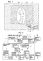
- the lighting control apparatus 1 displays a reference image 23c on a liquid crystal panel 21a as the monitor device 21, and then can also display outline images 23a and 23b as operation results of a pen 21b. Moreover, onto an inside of the projection-enabled range 2b by the projector 2, the lighting control apparatus 1 can project a reference image 2e corresponding to the reference image 23c, and further, can project the projection light 2a including the projection ranges 2c and 2d corresponding to the outline images 23a and 23b.
- the reference image 2e is first projected onto the projection target objects 3a and 3b and the wall surface 3'.
- the reference image 23c is displayed on the liquid crystal panel 21a, and the outline images 23a and 23b are set by using the shape drawing/input unit 20.
- the projection range parameter 12a is generated.
- the projection light data correction unit 13 corrects the projection light data 11a, and performs the drawing processing for the projection light correction data 13a, whereby projection ranges 2c-1 in which the projection target objects 3a and 3b are lightened can be formed from the projector 2.
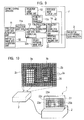
- the shape drawing/input unit 20 is not limited to the mouse, and may be the pen 21b that touches the liquid crystal panel 21a as in FIG. 13 .
- the lighting system as described above can allow the liquid crystal panel 21a to perform such an operation of setting the projection range 2c while allowing the user to visually recognize a correspondence relationship between the reference image 23c displayed on the liquid crystal panel 21a and the reference image 2e projected by the projection light 2a.
- the projection light 2a in which only the desired projection range 2c is emphasized among the projection-enabled range 2b can be projected more easily.
- the projection range 2c can be set by an intuitive operation like drawing a picture; however, the correspondence between the input position to the projection range setting unit 12 and the shape and position of the projection target object 3 is not presented, and accordingly, the projection range 2c must be designated in a manual exploratory state.
- the projection light 2a can be projected so as to include the reference image 2e in the projection-enabled range 2b including the projection target object 3, and the reference image 23c corresponding to the reference image 2e can be displayed on the liquid crystal panel 21a.
- the user can recognize the reference image 2e on the projection target objects 3a and 3b, and can draw the outline images 23a and 23b in agreement with the reference image 23c on the liquid crystal panel 21a.
- This lighting system is different from the above-mentioned lighting systems in correcting distortion of the reference image 2e in the case of projecting the reference image 2e onto the projection-enabled range 2b onto which the projection light 2a is projected from the reference image projector 2B.
- this lighting system includes: a reference image projection parameter input unit 51 as reference image projection parameter inputting means for inputting a parameter including a position, attitude and specifications (projection image angle, back focus, specified projection angle) of the reference image projector 2B that projects the reference image 2e; an operation position parameter input unit 52 as operation position parameter inputting means for inputting an operation position parameter indicating an operation position of the user who sets the projection range 2c by the projection range setting unit 12; a virtual plane parameter input unit 53 as virtual plane parameter inputting means for inputting a position, attitude and size of a planar region, which is virtually set on a projection region of the projected reference image 2e, in order to grasp a display state of the reference image 2e; and a reference image distortion correction parameter calculation unit 54 and a reference image data distortion correction unit 55, which serve as reference image distortion correcting means for correcting, based on the parameter of the reference image projector 2B, the operation position parameter and the virtual plane parameter, the reference image data so as to distort the projection light 2a
- the reference image projection parameter input unit 51, the operation position parameter input unit 52 and the virtual plane parameter input unit 53 input the parameters which affect the distortion of the reference image 2e.
- these parameter input units are composed of: a keyboard operated by the user and an input interface that recognizes operations to the keyboard; mechanisms which read a recording medium in which a variety of parameters are stored; mechanisms which receive a variety of parameters transmitted from the outside; and the like.
- the parameter for the reference image includes, as information affecting a distortion state of the reference image 2e, a position (coordinate information) and attitude (rotation angle information) of the projector 2 with respect to the projection target object 3 as a projection target of the projection light 2a.
- this parameter includes the projection image angle, the back focus, the specified projection angle and the like as the specifications of the reference image projector 2B, which affect the distortion state of the reference image 2e.
- the parameters of the reference image projector 2B may further include other detailed information as the specifications of the reference image projector 2B.
- the operation position parameter indicates the operation position with respect to the projection target object 3 as the projection target of the projection light 2a.
- This operation position may be a position of the personal computer that composes the reference image control device 4 (lighting control apparatus 1), or may be an eye-point position of the user, which is assumed from the position of the personal computer.
- the virtual plane parameter is a parameter for specifying a virtual plane onto which the projection light 2a is projected, and is information of a coordinate group that composes the virtual plane.
- This virtual plane parameter becomes such information that sets the virtual plane at an installed position of the projection target object 3a, for example, in a usage scene where the projection range 2c is set with respect to the projection target object 3.
- the reference image distortion correction parameter calculation unit 54 calculates and outputs a reference image distortion correction parameter 54a from the parameter for the reference image, the operation position parameter and the virtual plane parameter.
- the distortion occurs on the reference image 2e owing to the position, attitude and specifications of the reference image projector 2B, the operation position, and the position of the virtual plane.
- this reference image distortion correction parameter 54a gives distortion to the reference image data 32a, and thereby can allow the reference image 2e to be visually recognized on the virtual plane free from the distortion.
- the reference image distortion correction parameter 54a indicates a correspondence relationship (correspondence map) between coordinate information of the reference image data 32a as a two-dimensional rectangular image and coordinate information of the corrected reference image data 32a from which the distortion is eliminated, the distortion occurring owing to the actual position, attitude and specifications of the reference image projector 2B, the operation position, and the position of the virtual plane.
- the reference image data distortion correction unit 55 performs coordinate conversion processing (texture mapping), which uses the distortion correction parameter 54a supplied from the reference image distortion correction parameter calculation unit 54, for the reference image data 32a supplied from the reference image data generation unit 32.
- the reference image data 32a calculates such reference image distortion correction data 55a that allows the reference image 2e to look like free from the distortion from the user at the time when the reference image 2e is projected by the reference image projector 2B, and then supplies the calculated reference image distortion correction data 55a to the reference image data drawing unit 33.
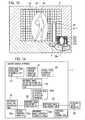
- the reference image control device 4 As described above does not perform the distortion correction, then as shown in FIG. 15 , when the reference image 2e is projected onto the virtual plane, the reference image 2e is projected while being distorted owing to the position, attitude and specifications of the reference image projector 2B, and to the operation position. As opposed to this, the reference image control device 4 generates the reference image distortion correction parameter 54a based on the position, attitude and specifications of the reference image projector 2B, the operation position, and the position of the virtual plane, which cause the distortion of the reference image 2e, and then implements the coordinate conversion as distortion correction processing for the reference image data 32a.
- the reference image control device 4 can correct the projection-enabled range 2b for the reference image 2e so that the projection-enabled range 2b can become a new projection-enabled range 2b' for which the distortion correction is done.
- the reference image 23c displayed on the liquid crystal panel 21a and the reference image 2e on the virtual plane 2f can be associated with each other.
- the projection ranges 2c and 2d can be set simply by projecting the reference image 2e, which is free from the distortion, onto the projection position concerned.
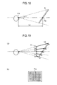
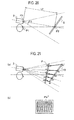
- a flat object S is considered, which is spaced apart from the user by a distance L, and is arranged so as to be inclined obliquely with respect to the user.
- This flat object S is visually recognized from an eye-point position P1 of the user at a viewing angle ⁇ 1.
- the user and a point P2 on the flat object S, which intersects a center of a viewing field of the user, are spaced apart from each other by a distance L1.
- points b1, b2, b3, b4 and b5 on the video surface U correspond to points a1, a2, a3, a4 and a5 on the flat object S.
- videos displayed on the points a1, a2, a3, a4 and a5 on the flat object S are visually recognized as the points b1, b2, b3, b4 and b5 on the video surface U from the user.
- the point P2 where a line of sight of the user and the flat object S intersect each other and a projection position P3 of the projector 2 are spaced from each other by a distance L2.
- the projector 2 projects the projection light within a range of a predetermined projection angle of view ⁇ 2.
- the points a1, a2, a3, a4 and a5 on the flat object S correspond to points c1, c2, c3, c4 and c5 on the video surface P.
- points on straight lines extended from the projection position P3 of the projector 2 through the points c1, c2, c3, c4 and c5 on the video surface P become the points a1, a2, a3, a4 and a5 on the flat object S.
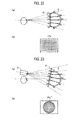
- the eye-point position P1 and viewing angle ⁇ 1 of the user, the position of the flat object S, and the projection position P3 and projection angle of view ⁇ 2 of the projector 2 have the relationships thereamong as described above. Accordingly, when videos are projected onto the points c1, c2, c3, c4 and c5 on the video surface P in the projector 2, which is shown in FIG. 21(a) , the videos are projected onto the points a1, a2, a3, a4 and a5 on the flat object S. As a result, the points a1, a2, a3, a4 and a5 on the flat object S are visually recognized as the points b1, b2, b3, b4 and b5 on the video surface U in FIG. 19 .
- the lighting system acquires an eye-point position/attitude parameter that indicates an eye-point position indicating the eye-point position P1 of the user and indicates a line-of-sight direction of the user, and acquires a viewing angle parameter that indicates the viewing angle ⁇ 1 of the user.
- the lighting system acquires shape data of the flat object S onto which the projection light emitted from the projector 2 is projected.
- This shape data is, for example, CAD data.
- the eye-point position/attitude parameter is the one in which positions on X-, Y- and Z-axes and rotation angles about the axes in a three-dimensional coordinate space are numerically defined.
- This eye-point position/attitude parameter uniquely determines the distance L1 between the eye-point position P1 and the flat object S, and the attitude of the flat object S with respect to the eye-point position P1.
- the shape data of the flat object S is the one in which a shape region in the three-dimensional coordinate space is defined based on electronic data generated by CAD and the like.
- This shape data uniquely determines the shape of the flat object S viewed from the eye-point position P1.
- the shape data of the flat object S which is as described above, and the parameters of the user determine the correspondence relationship between the coordinate of the video surface U and the coordinate of the flat object S.
- the lighting system acquires a position/attitude parameter that indicates the projection position P3 of the projector 2 and an optical axis direction of the projector 2 concerned, and acquires a projection angle-of-view parameter that indicates the projection angle of view ⁇ 2 of the projector 2.
- These position/attitude parameter and projection angle-of-view parameter of the projector 2 indicate the video surface P projected onto the flat object S by the projector 2.
- this video surface P is determined, it is determined onto which coordinate of the flat object S the projection light projected from the projector 2 is projected through the video surface P.
- the position/attitude parameter and projection angle-of-view parameter of the projector 2 and the position/attitude parameter and shape data of the flat object S uniquely determine the range of the flat object S covered with the projection light emitted from the projector 2.
- the projection position P3 is defined by a back focus and specified projection angle thereof, and the projection angle of view ⁇ 2 is calculated from a horizontal and vertical projection range located apart from the projection position P3 by a fixed distance.
- the lighting system arranges pixels on intersections (c1, c2, c3, c4, c5) between the video surface P and the straight lines which connect the pixels (a1, a2, a3, a4, a5) of the projection light displayed on the flat object S and the projection position P3 of the projector 2 to each other, thereby composes the two-dimensional video Pic", and projects the two-dimensional video Pic" onto the flat object S.
- the user can be allowed to visually recognize the video free from the distortion through such a route of the points c1, c2, c3, c4 and c5 on the video surface P, the points a1, a2, a3, a4 and a5 on the flat object S, and the points b1, b2, b3, b4 and b5 on the video surface U.
- the projection target object 3 does not have such a shape of the flat object S but has an arbitrary shape such as a dome shape
- the projection light is projected thereonto free from the distortion, whereby the user can be allowed to visually recognize the projection target object 3 concerned.
- the projection target object 3 is the dome-like object S as shown in FIG. 22(a)
- the user is allowed to visually recognize grid-like projection light as shown in FIG. 22(b) .
- points a1, a2, a3, a4 and a5 on the dome-like object S which are located on extensions of the points b1, b2, b3, b4 and b5 on the video surface U.
- the projector 2 projects the projection light onto the video surface P as shown in FIG. 23(a) .
- the projection light that has passed through the points c1, c2, c3, c4 and c5 on the video surface P is projected onto the points a1, a2, a3, a4 and a5 on the dome-like object S, and is visually recognized as the points b1, b2, b3, b4 and b5 on the video surface U shown in FIG. 22(a) .
- the projector 2 projects a two-dimensional video Pic", which is distorted as shown in FIG. 23(b) , onto the video surface P. While the projector 2 projects the two-dimensional video Pic" as described above, the user can visually recognize a two-dimensional video Pic without the distortion as shown in FIG. 22(b) .
- this lighting system includes: a flat screen 6 onto which the reference image 2e is projected by the reference image projector 2B; a camera device 5 as photographing means for photographing the reference image 2e projected onto the flat screen 6; and a reference image distortion correction parameter calculation unit 54 and a reference image data distortion correction unit 55, which serve as reference image distortion correcting means for distorting the reference image, which is projected from the reference image projector 2B, so as to make coincidence between the reference image 2e projected onto the flat screen 6, which is acquired by photographic data generated by the camera device 5, and the reference image generated by the reference image data generation unit 32.
- the flat screen 6 is installed as shown in FIG. 25 .
- An installed position of this flat screen 6 is set at an installation-scheduled position of the projection target object 3 serving as the projection target of the projection light 2a.
- this flat screen 6 is of a retract mode in consideration of portability.
- the camera device 5 includes: a photographing unit 61 composed of a photographing device such as a CCD, optical components, and the like; and a photographed image data output unit 62 that outputs photographed image data 61a, which is photographed by the photographing unit 61, to the reference image control device 4. It is desirable that this camera device 5 be installed in the vicinity of the operation position of the user, and in an example shown in FIG. 25 and the like, the camera device 5 is installed on the monitor device 21. It is not necessary to particularly limit the place where this camera device 5 is installed, and this place may be arbitrarily set as long as the reference image distortion correction parameter can be generated so that the reference image 2e viewed from the user can be projected free from the distortion.
- the reference image control device 4 includes a photographed image data input unit 63 that inputs the photographed image data 61a outputted from the photographed image data output unit 62.
- the reference image distortion correction parameter 54 calculates the reference image distortion correction parameter 54a for the distortion correction of the reference image 2e by using photographed image data 63a outputted from the photographed image data input unit 63.
- the reference image distortion correction parameter 54 generates the reference image distortion correction parameter 54a so that the reference image 2e, which is projected onto the flat screen 6 and is acquired by the photographed image data 61a generated by the camera device 5, can be allowed to coincide with the projection-enabled range 2b' having a predetermined shape.
- the reference image distortion correction parameter calculation unit 54 allows the distorted reference image 2e displayed on the flat screen 6 to coincide with the reference image generated by the reference image data generation unit 32. In such a way, the reference image distortion correction parameter calculation unit 54 turns the reference image 2e displayed on the flat screen 6 into a non-distortion state similar to that in the reference image 23c displayed on the liquid crystal panel 21a.
- the reference image control device 4 performs the coordinate conversion as the distortion correction processing for the reference image data 32a by using the reference image distortion correction parameter 54a, and supplies the reference image distortion correction data 55a to the reference image data drawing unit 33.
- the projection light in which the distortion is corrected is projected from the reference image projector 2B onto the flat screen 6 in accordance with the reference image drawing data 33a, whereby the reference image 23c displayed on the liquid crystal panel 21a and the reference image 2e displayed on the flat screen 6 can be allowed to coincide with each other in a visual sense of the user who recognizes the reference images.
- the reference image 2e is projected from the reference image projector 2B onto the flat screen 6 by using the reference image data 32a that is not still subjected to the distortion correction processing.
- the reference image 2e is distorted to a shape of a trapezoid
- the reference image 2e having such distortion is photographed by the camera device 5, and the photographed image data 61a is supplied to the reference image distortion correction parameter calculation unit 54.
- this lighting system can revise the projection-enabled range 2b for the reference image 2e on the flat screen 6, which is photographed by the camera device 5, into the new projection-enabled range 2b' for which the distortion correction is done.
- the reference image 23c displayed on the liquid crystal panel 21a and the reference image 2e projected from the reference image projector 2B can be associated with each other.
- the projection ranges 2c and 2d can be set simply by projecting the reference image 2e, which is free from the distortion, onto the projection position concerned.
- the flat screen 6 is installed at the installed position of the projection target objects 3a, 3b and the like, and the distortion of the reference image 2e is automatically corrected, and then the projection ranges 2c and 2d can be set by projecting the reference image 2e, whereby the setting of the projection ranges 2c and 2d can be performed more simply.
- the reference image data 32a can be automatically corrected so as to eliminate the distortion. In such a way, it is possible to omit calibration that must be performed due to an error between the input of the variety of parameters and arrangement accuracy of the reference image projector 2B and the like (that is, a difference between the actual arrangement positions and the input parameters).
- a lighting control apparatus 1 in this lighting system includes: a projection range identification condition setting unit 71 that receives conditions for specifying the projection range 2c; and a projection range identification unit 72 that identifies the projection range 2c in accordance with the conditions received by the projection range identification condition setting unit 71.
- This lighting control apparatus 1 corrects the projection light data so that the projection light data can correspond to the projection range 2c identified by the projection range identification unit 72, and projects the light from the projector 2.
- This lighting control apparatus 1 automatically sets the projection range 2c without using the camera device 5 mentioned above.
- this lighting system divides the projection-enabled range 2b of the projector 2 into squares of a matrix, which have an arbitrary size, designates the respective squares, and thereby sets the projection range 2c.
- the projection range identification condition setting unit 71 is composed of a mouse similar to the shape drawing/input unit 20, displays the squares on the monitor device 21, and designates the respective squares by a mouse operation.
- the projection range 2c can be set on the projection target object 3 or the space, which corresponds to the squares designated by the mouse. Note that, in the example of FIG. 29 , only the squares before the light is projected thereonto are shown.
- a configuration may be adopted, in which an operation of drawing a skeleton line 23d on the monitor device 21 is performed, thus making it possible to set, as a projection range 23e, a range of a predetermined width from the skeleton line 23d.
- setting icons 23f are displayed on the monitor device 21, and in response to the mouse operation, there are designated an end point, eye-point and thickness of the skeleton line 23d, a width of the projection range 2c for the skeleton line 23d, and characteristics of the projection light, whereby the projection range 2c can be set on the projection target object 3.
- the projection range identification unit 72 identifies a correspondence relationship between positions in the projection-enabled range 2b and a pair of the squares and the predetermined range having the skeleton line taken as the center, which are designated as the projection range 2c, by using the projection range identification condition parameter 71a. In such a way, the lighting system recognizes the actual projection range 2c, generates a projection range identification parameter 72a, and supplies the projection range identification parameter 72a to the projection light data correction unit 13.
- this projection range identification unit 72 is data indicating the projection range 2c, onto which the light is projected, or the non-projection range by the coordinates on the projection-enabled range 2b of the projector 2.
- the projection light data correction unit 13 can correct the projection light data 11a by using the projection range identification parameter 72a, and can correct the projection light correction data 13a.
- the projection range 2c can be set simply by designating the projection range 2c by using the projection range identification condition setting unit 71.
- this lighting system outputs the photographed image data 61a, which is generated by the camera device 5, to the photographed image data input unit 63 of the lighting control apparatus 1, and performs display, which uses the photographed image data 61a, by a photographed image data display unit 86.
- this photographed image data display unit 86 is a liquid crystal display that also serves as the liquid crystal panel 21a.
- this lighting system includes: a photographic parameter input unit 81 as photographic parameter inputting means for inputting a photographic parameter including a position, attitude and specifications of the camera device 5; a projection light projection parameter input unit 82 as projection light projection parameter inputting means for inputting the position, attitude and specifications of the projector 2; a virtual plane parameter input unit 83 as virtual plane parameter inputting means for inputting a virtual plane parameter including the position, attitude and size of the virtually set planar region in order to grasp the state of the projection range 2c of the projector 2; and a projection light distortion correction parameter arithmetic unit 84 and a projection light data distortion correction unit 85, which serve as projection light data correcting means for correcting, based on the photographic parameter, the projection light projection parameter and the virtual plane parameter, the projection light data 11a so as to allow the projection light to coincide with a photographic range of the camera device 5 on the virtual plane.
- a photographic parameter input unit 81 as photographic parameter inputting means for inputting a photographic parameter including a position, attitude and specifications of the camera device 5
- the photographic parameter input unit 81, the projection light projection parameter input unit 82 and the virtual plane parameter input unit 83 input the parameters which affect the distortion of the projection range 2c projected from the projector 2.
- these parameter input units are composed of: the keyboard operated by the user and the input interface that recognizes the operations to the keyboard; the mechanisms which read the recording medium in which the variety of parameters are stored; the mechanisms which receive the variety of parameters transmitted from the outside; and the like.
- the photographic parameter includes a position, attitude and specifications (camera image angle and the like) of the camera device 5 as information affecting the distortion state of the projection range 2c. Note that the photographic parameter may further include other detailed information.
- the projection light projection parameter includes, as the information affecting the distortion state of the projection range 2c, the position (coordinate information) and attitude (rotation angle information) of the projector 2 with respect to the projection target object 3 as the projection target of the projection light 2a. Moreover, this projection light projection parameter includes the projection image angle, the back focus, the specified projection angle and the like as the specifications of the projector 2, which affect the distortion state of the projection range 2c. Note that the projection light projection parameter may further include other detailed information as the specifications of the projector 2.
- the virtual plane parameter is the parameter for specifying the virtual plane onto which the projection light 2a is projected, and is the information of the coordinate group that composes the virtual plane.
- This virtual plane parameter becomes such information that sets the virtual plane at a position correctly opposed to the camera device 5, which is also the installed position of the projection target object 3, for example, in the usage scene where the projection range 2c is set with respect to the projection target object 3.
- the projection light distortion correction parameter arithmetic unit 84 calculates and outputs a projection light distortion correction parameter 84a from the photographic parameter, the projection light projection parameter and the virtual plane parameter. Although the distortion occurs on the projection range 2c owing to the positions, attitudes and specifications of the camera device 5 and the projector 2, and to the position of the virtual plane, this projection light distortion correction parameter 84a gives the distortion to the projection light data 11a, and thereby corrects the projection light data 11a so that the projection light 2a can coincide with the photographic range of the camera device 5 on the virtual plane.
- the projection light distortion correction parameter arithmetic unit 84 obtains a photographic range 5a of the camera device 5 on the virtual plane from an image angle of the photographing unit 61 in the camera device 5 and from a position of the virtual plane 2f with respect to the camera device 5 by using the virtual plane parameter and the photographic parameter. Then, the projection light distortion correction parameter arithmetic unit 84 arithmetically operates the projection light distortion correction parameter 84a indicating a correspondence relationship between coordinate information of the projection-enabled range 2b on the virtual plane 2f as a rectangular two-dimensional image and coordinate information of such corrected projection-enabled range 2b that coincides with the projection range 5a on the virtual plane 2f.
- the projection light data distortion correction unit 85 performs coordinate conversion using the projection light distortion correction parameter 84a supplied from the projection light distortion correction parameter arithmetic unit 84. In such a way, from the projection light data 11a, there is calculated such projection light distortion correction data 85a that allows the projection of such a projection range 2c that looks like free from the distortion from the user at the time when the projection light 2a is projected by the projector 2. Then, the calculated projection light distortion correction data 85a is supplied to the projection light data correction unit 13.
- the lighting system even if the photographic range 5a of the camera device 5 on the certain virtual plane 2f is defined, and the projection light 2a is projected from the projector 2, the projection light 2a forms the projection-enabled range 2b distorted to the shape of the trapezoid with respect to the photographic range 5a.
- the lighting system allows the projection-enabled range 2b and the photographic range 5a to coincide with each other, whereby the distortion can be eliminated from the projection ranges 2c-1 and 2c-2 as shown in FIGS. 34 and 35 .
- PIG. 35 shows an example of using the pen 21b in place of the mouse.
- the outline images 23a and 23b are only designated to the liquid crystal panel 21a by the pen 21b in the state where the photographed image data 61a photographed by the camera device 5 is displayed on the liquid crystal panel 21a, whereby the projection ranges 2c-1 and 2c-2 corresponding to the outline images 23a and 23b concerned can be formed as shown in FIG. 34 and PIG. 35.
- the operation is performed to the liquid crystal panel 21a, whereby accuracy of the correspondence relationship between the outline images 23a and 23b set on the liquid crystal panel 21a and the actual projection ranges 2c-1 and 2c-2 can be enhanced.
- the lighting system shown as the ninth embodiment includes: a projection range extraction setting unit 91 as projection range extraction setting means for setting conditions for extracting the projection range 2c; and a projection range classification unit 92 as classifying means for classifying the projection range 2c and the non-projection range other than the projection range concerned with each other by analyzing the photographic data, which is generated by the camera device 5, in accordance with the conditions set by the projection range extraction setting unit 91.
- This lighting system corrects the projection light distortion correction data 85a for correcting the projection light data by the projection light data correction unit 13 based on the projection range and the non-projection range, which are classified with each other by the projection range classification unit 92.
- the projection range extraction setting unit 91 analyzes the photographed image data 61a photographed by the camera device 5, and as the conditions for extracting the projection range 2c onto which the projection light is projected, sets extraction methods such as an approximate color extraction method of extracting the projection range 2c based on a color, a shape extraction method of extracting the projection range 2c based on a shape, and a lightness extraction method of extracting the projection range 2c based on lightness, and sets threshold values in the extraction methods concerned, and the like.
- the projection range extraction setting unit 91 is composed of: the keyboard operated by the user and the input interface that recognizes operations to the keyboard; the mechanism that reads the recording medium in which the variety of parameters are stored; the mechanism that receives the variety of parameters transmitted from the outside; and the like.
- the extraction conditions of the projection range 2c, which are set by the projection range extraction setting unit 91, are supplied as a projection range extraction parameter 91a to the projection range classification unit 82.
- the projection range classification unit 82 analyzes the photographed image data 63a supplied from the photographed image data input unit 63. As a result of this analysis, the projection range classification unit 82 supplies, to the projection light data correction unit 13, a projection range classification parameter 92a as coordinate information indicating a projection range that has conformed to the projection range extraction parameter 91a. In such a way, by the projection light data correction unit 13, the lighting system can generate projection light correction data 13a for projecting the projection light only onto the projection range 2c that has conformed to the extraction conditions set by the projection range extraction setting unit 91.
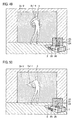
- the camera device 5 in order to set the projection range 2c for the projection target objects 3a and 3b as shown in FIG. 37 , the camera device 5 generates the photographed image data 61a including the projection target objects 3a and 3b, and supplies the photographed image data 61a thus generated to the photographed image data input unit 63. Then, by using the photographed image data 63a supplied from the photographed image data input unit 63 to the photographed image data display unit 86, the photographed image data display unit 86 that is allowed to also serve as the liquid crystal panel 21a displays a photographed image that includes an object image 5c showing the projection target objects 3a and 3b. Meanwhile, upon receiving the photographed image data 63a, the projection range classification unit 82 analyzes the photographed image data 63a concerned in accordance with the projection range extraction parameter 91a, and classifies the projection range 2c and the non-projection range with each other.
- the projection range extraction parameter 91a in which the extraction conditions of the projection range 2c are: "shape extraction processing"; and “cubic regions are included into the projection range 2c, and a region other than the cubic regions are set as the non-projectian range", is supplied to the projection range classification unit 92.
- the projection range classification unit 92 is supplied with the photographed image data 63a including the object image 5c of the cubes. Then, the projection range classification unit 92 recognizes shape edges, which cover the entirety of the photographed image data 63a, by edge extraction processing, then includes the cubic regions into the projection range 2c, and sets the region other than the cubic regions as the non-projection range.
- a classification result of the projection range which is acquired by the projection range classification unit 92 as described above, is displayed as outline information 5c' on the liquid crystal panel 21a as shown in FIG. 38 . Moreover, a projection range parameter 82a indicating this classification result is supplied to the projection light data correction unit 13.
- the lighting system allows the projection light data correction unit 13 to generate the projection light correction data 13a in accordance with the projection range parameter 82a, actuates the projection light correction data drawing unit 14 and the projector 2, and thereby can generate the projection light 2a for projecting the projection light onto the projection range of the cubic regions.
- the projection light can be projected only onto the projection range of the projection target objects 3a and 3b.
- this lighting system may arrange a blue sheet, which is prepared for enhancing extraction accuracy in the color extraction processing, behind the projection target objects 3a and 3b.
- the projection range extraction setting unit 91 sets a projection range extraction parameter 91a, in which the extraction conditions of the projection range are: "color extraction processing”; and "a blue region is set as the non-projection range, and a region other than the blue region is set as the projection range 2c", and supplies the set projection range extraction parameter 91a to the projection range classification unit 92.
- the projection range classification unit 92 implements color extraction processing for classifying the blue region and the region other than the blue region with each other, and can thereby generate the outline information 5c' of the projection target objects 3a and 3b as the projection range parameter 82a.
- the projection light correction data 75a is generated by the projection light data distortion correction unit 75 so as to allow the photographic range 5a of the camera device 5, which includes the projection target objects 3a and 3b, and the projection-enabled range 2b of the projector 2 to coincide with each other as shown in FIG. 40 .
- the liquid crystal panel 21a there can be displayed: a classification result confirmed on the liquid crystal panel 21a concerned; and an image including the object image 5c, which is obtained as a result of projecting the projection light onto the projection range automatically set in accordance with the classification result concerned.
- this lighting system may paste dot-like markers 3c onto the projection target object 3 as shown in FIG. 41 , and may set, as the projection range 2c, predetermined ranges having the dot-like markers 3c concerned taken as centers. Then, when the photographed image data 63a is supplied to the projection range classification unit 92 in a state where the projection range extraction parameter 91a indicating this condition is supplied thereto, the projection range classification unit 92 analyzes the photographed image data 63a, and recognizes positions of the dot-like markers 3c.
- the projection range classification unit 92 generates the projection range classification parameter 92a, in which the predetermined circular ranges having the markers 3c taken as the centers are set as the projection range 2c, and the range other than these circular ranges is set as the non-projection range, and supplies the generated projection range classification parameter 92a to the projection light data correction unit 13.
- the predetermined circular ranges including the markers 3c on the projection target object 3 can be set as the projection ranges 2c-1, and the range other than the projection ranges 2c-1 can be set as the projection range 2c-2.
- the ranges of the projection range 2c which are set for the dot-like markers 3c, can be set at an arbitrary size in response to the operation of the user.
- the shape of the projection range 2c is not limited to the round shape, and can be set at an arbitrary shape such as a quadrangular shape in response to the operation of the user.
- this lighting system may paste a linear marker 3c onto the projection target object 3 as shown in FIG. 43 , and may set a range of a predetermined width, which uses the marker 3c concerned as a skeleton line, as the projection range 2c. Then, when the photographed image data 63a is supplied to the projection range classification unit 92 in a state where the projection range extraction parameter 91a indicating this condition is supplied thereto, the projection range classification unit 92 analyzes the photographed image data 63a, and recognizes positions (starting point, end point, length) of the linear marker 3c.
- the projection range classification unit 92 generates the projection range classification parameter 92a, in which the range of the predetermined width, which uses the marker 3c as the skeleton line, is set as the projection range 2c, and the range other than the projection range 2c is set as the non-projection range, and supplies the generated projection range classification parameter 92a to the projection light data correction unit 13.
- the range of the predetermined width which includes the marker 3c on the projection target object 3
- the range other than the projection range 2c-1 can be set as the projection range 2c-2.
- a width of the projection range 2c set with respect to the linear maker 3c can be set at an arbitrary size in response to the operation of the user.
- the projection range 2c may be made capable of being held based on the markers 3c even if the markers 3c are detached after such a predetermined range having the markers 3c taken as the centers or the skeleton is set as the projection range 2c.
- the lighting control apparatus 1 include means for recording the projection range classification parameter 92a generated by the projection range classification unit 92.
- Such a configuration may be adopted, in which a three-dimensional shape of the projection target object 3 is scanned by using the photographed image data 63a obtained by photographing the projection target object 3 by means of a plurality of the camera devices 5, and the projection range 2c is decided so as to cover the three-dimensional shape of the projection target object 3.
- a lighting control apparatus 1 of the lighting system shown as the ninth embodiment is different from the lighting control apparatus 1 shown in FIG. 4 in that a projection range revision unit 101 that revises a boundary of the projection range 2c in accordance with the operation of the user is connected to the projection light data correction unit 13.
- this lighting system may adopt a configuration of including such a projection range revision unit 101 as revising means for revising the projection range and the non-projection range, which are classified with each other by the projection range classification unit 82, in accordance with the operation of the user.
- This projection range revision unit 101 is composed of: the pen 21b and the liquid crystal panel 21a; the keyboard operated by the user and the input interface that recognizes the operations to the keyboard; and the like.
- the lighting system displays, as the classification result, the projection range 2c and the non-projection range on the liquid crystal panel 21a in accordance with the projection range parameter 82a generated by the projection range classification unit 92.
- the projection range revision unit 101 recognizes that an operation of changing the projection range 2c or the non-projection range is performed in such a manner that the user operates the pen 21b that composes the projection range revision unit 101.
- the projection range revision unit 101 generates a command to the effect that coordinate information indicating the projection range 2c or the non-projection range is to be changed, and supplies the generated command to the projection light data correction unit 13.
- the projection light data correction unit 13 Upon being supplied with the command to change the projection range 2c or the non-projection range, the projection light data correction unit 13 performs revision processing for the projection range parameter 82a. Specifically, the projection light data correction unit 13 converts coordinate information of the still unrevised projection range 2c and non-projection range, which compose the projection range parameter 82a, into coordinate information of the revised projection range 2c and non-projection range. Then, by using the revised projection range parameter 82a, the projection light data correction unit 13 can correct the projection light correction data 85a and can generate the projection light correction data 13a.
- the projection range 2c and the non-projection range which are automatically set by the lighting system shown in FIG. 4 or FIG. 36 , can be revised by the projection range revision unit 101 in response to the operation of the user.
- the projection range 2c among the projection-enabled range 2b can be set more simply.
- the projection range revision unit 101 it is detected that, when a projection target object image 24 that becomes the projection range 2c is displayed on the liquid crystal panel 21a as shown in FIG. 49 , an operation of moving a pointer 26 is performed to enlarge or reduce a selected region 25 that surrounds the projection target object image 24.
- the projection range revision unit 101 can revise the projection range 2c in response to the operation of the user. For example, in the case where the selected region 25 is enlarged by the operation of the pointer 26, the projection range revision unit 101 can revise the projection range 2c-1, which is projected onto the projection target object 3, into an enlarged projection range 2c'-1.
- a method may be adopted, in which the selected region 25 going along the projection target object image 24 is set, a part of the selected region 25 concerned is selected by the pointer 26, and the selected region 25 is deformed, whereby the projection range 2c may be revised.
- the projection range revision unit 101 can revise the projection range 2c-1, which corresponds to the part concerned, to a projection range 2c'-1 deformed therefrom.
- the projection range revision unit 101 may deform the projection range 2c.
- FIG. 51 when the reference image 2e is projected onto the projection target obj ect 3, and the reference image 23c is displayed on the liquid crystal panel 21a, then as shown in FIG. 52 , it is assumed that the reference image 23c is deformed on the liquid crystal panel 21a by a mouse operation of the user, which is similar to that of the shape drawing/input unit 20.
- the projection range revision unit 101 may deform the projection range 2c.
- the projection range revision unit 101 detects an operation of deforming the reference image 23c corresponding to an arm portion of the projection target object 3, and can thereby deform a grid that composes the reference image 2e concerned to then revise the grid into a reference image 2e', and can deform the projection range 2c-1 analogously to a way of distortion of the grid that composes the reference image 2e to then revise the projection range 2c-1 to a projection range 2c'-2.
- the projection light data 11 is stored in advance, and output control in accordance therewith is performed, whereby the projection light 2a projected from the projector 2 may be updated.
- This lighting system includes: a projection light data storage unit 111 as projection light data storing means for storing the projection light data 11a; a projection light data update setting unit 113 as projection light data output setting means for setting at least either of an output order and output condition of the projection light data 11a stored in the projection light data storage unit 111; and a projection light data output update unit 112 as projection light data updating means for outputting the projection light data 11a, which is stored in the projection light data storage unit 111, in accordance with the at least either of the output order and the output condition, which is set by the projection light data update setting unit 113.
- the projection light data storage unit 111 is composed of a hard disk device in the personal computer, an external storage device, or the like. This projection light data storage unit 111 is supplied with plural pieces of the projection light data 11a generated by the projection light data generation unit 11. As the plural pieces of projection light data 11a, there are set varieties of colors, brightnesses and contrasts for each of the projection range and the non-projection range.
- the projection light data update setting unit 113 sets update information, which indicates the output order and output condition of the projection light 2a, by a keyboard operation of the user to the personal computer.
- the output order of the projection light 2a there are mentioned: an order of outputting plural pieces of the projection light 2a based on the projection light data 11a; a projection time and update interval of each piece of the projection light 2a; and the like.
- the projection light data 11a is read out by the projection light data output update unit 112 to then start the projection of the projection light 2a when a button provided on a controller 114 that composes the personal computer is operated; the next projection light data 11a is read out to then update the projection light 2a at the time of operating the button; and the like.
- the projection light 2a desired to be projected is selected in advance, whereby the projection light data 11a for use is selected in advance, and an update order and an update condition are set in advance.
- the projection light data output update unit 112 reads out the projection light data 11a from the projection light data storage unit 111 in accordance with the update order and update condition of the projection light 2a, which are set by the projection light data update setting unit 113, and then supplies the projection light data 11a thus read out to the projection light data correction unit 13.
- the lighting system can project the projection light 2a, which is set by the user, in desired order and interval, and can instantaneously change the characteristics (color, brightness, contrast) of the light in the projection range projected by the projection light 2a.
- this lighting system may store the projection range parameter 12a in advance to then perform output control in accordance therewith, and may thereby update the projection range and the non-projection range among the projection light 2a projected from the projector 2.
- This lighting system includes: a projection range parameter storage unit 121 as projection range parameter storing means for storing the projection range parameter 12a as a projection range parameter for correcting the projection range by the projection light data correction unit 13; a projection range parameter update setting unit 123 as projection range output setting means for setting at least either of an output order and output condition of the projection range parameter 12a stored in the projection range parameter storage unit 121; and a projection range parameter output update unit 122 as projection range parameter updating means for outputting the projection range parameter 12a, which is stored in the projection range parameter storage unit 121, in accordance with the at least either of the output order and the output condition, which is set by the projection range parameter update setting unit 123.
- the projection range parameter storage unit 121 is composed of the hard disk device in the personal computer, the external storage device, or the like. This projection range parameter storage unit 121 is supplied with a plurality of the projection range parameters 12a generated by the projection range setting unit 12. As the plurality of projection range parameters 12a, there are included patterns of the projection ranges and the non-projection ranges, which have various shapes.
- the projection range parameter update setting unit 123 sets update information, which indicates the output order and output condition of the projection range parameter 12a, by the keyboard operation of the user to the personal computer.
- the order and condition of the projection range desired to be changed are the update information.
- the output order of the projection range parameter 12a there are mentioned: an order of changing a plurality of the projection ranges; a projection time and update interval of each of the projection ranges; and the like.
- the output condition of the projection range parameter 12a for example, there are mentioned: that the projection range parameter 12a is read out by the projection range parameter output update unit 122 to then update the projection range to a new one when the button provided on the controller 114 that composes the personal computer is operated; and the like.
- the desired projection range is selected in advance, whereby the projection range parameter 12a for use is selected in advance, and the update order and the update condition are set in advance.
- the projection range parameter output update unit 122 reads out the projection range parameter 12a from the projection range parameter storage unit 121 in accordance with the update order and update condition of the projection range, which are set by the projection range parameter update setting unit 123, and then supplies the projection range parameter 12a thus read out to the projection light data correction unit 13.
- the lighting system can project the projection light 2a onto the projection range, which is selected by the user, in the desired order and interval, and can instantaneously change the projection range projected by the projection light 2a.
- this lighting system may store the projection light correction data 13a, which is obtained by correcting the projection light data 11a by the projection light data correction unit 13, in advance to then perform output control in accordance therewith. In such a way, the lighting system can update the projection range and the non-projection range among the projection light 2a projected from the projector 2.
- This lighting system includes: a projection light correction data storage unit 131 as projection light correction data storing means for storing the projection light correction data 13a corrected by the projection light data correction unit 13; a projection light correction data update setting unit 133 as projection light correction data output setting means for setting at least either of an output order and output condition of the projection light correction data 13a stored in the projection light correction data storage unit 131; and a projection light correction data output update unit 132 as projection light data updating means for outputting the projection light data, which is stored in the projection light correction data storage unit 131, in accordance with the at least either of the output order and the output condition, which is set by the projection light correction data update setting unit 133.
- the projection light correction data storage unit 131 is composed of the hard disk device in the personal computer, the external storage device, or the like. This projection light correction data storage unit 131 is supplied with the projection light correction data 13a in which the projection range is corrected by the projection light data correction unit 13. This projection light correction data 13a is accumulated in the projection light correction data storage unit 131 every time when new projection light correction data 13a is generated by the projection light data correction unit 13, and those in which the projection ranges and the non-projection ranges are formed into a variety of shapes are included therein.
- the projection light correction data update setting unit 133 sets update information, which indicates the output order and output condition of the projection light correction data 13a, by the keyboard operation of the user to the personal computer.
- the order and condition of the projection range desired to be changed are the update information.
- the output order of the projection light correction data 13a there are mentioned: an order of changing the projection ranges; a projection time and update interval of each of the projection ranges; and the like.
- the output condition of the projection light correction data 13a for example, there are mentioned: that the projection light correction data 13a is read out by the projection light correction data output update unit 132 to then update the projection range to a new one when the button provided on the controller 114 that composes the personal computer is operated; and the like.
- the desired projection range is selected in advance, whereby the projection light correction data 13a is selected in advance, and the update order and the update condition are set in advance.
- the projection light correction data output update unit 132 reads out the projection light correction data 13a from the projection light correction data storage unit 131 in accordance with the update order and update condition of the projection range, which are set by the projection light correction data update setting unit 133, and then supplies the projection light correction data 13a thus read out to the projection light correction data drawing unit 14.
- the lighting system can project the projection light 2a onto the projection range, which is selected by the user, in the desired order and interval, and can instantaneously change the projection range projected by the projection light 2a.
- this lighting system may store the reference image data 32a in advance to then perform output control in accordance therewith, and may thereby update the reference image 2e projected by the reference image projector 2B and the reference image 23c displayed on the liquid crystal panel 21a.
- This lighting system includes: a reference image data storage unit 141 as reference image data storing means for storing the reference image data 32a generated by the reference image data generation unit 32; a reference image data update setting unit 143 as reference image data output setting means for setting at least either of an output order and output condition of the reference image data 32a stored in the reference image data storage unit 141; and a reference image data output update unit 142 as reference image updating means for outputting the reference image data 32a, which is stored in the reference image data storage unit 141, in accordance with the at least either of the output order and the output condition, which is set by the reference image data update setting unit 143.
- the reference image data storage unit 141 is composed of the hard disk device in the personal computer, the external storage device, or the like. This reference image data storage unit 141 is supplied with the reference image data 32a generated by the reference image data generation unit 32.
- This reference image data 32a includes those of grid patterns and grid dots, which have a variety of dimensions.
- the reference image data update setting unit 143 sets update information, which indicates the output order and output condition of the reference image data 32a, by the keyboard operation of the user to the personal computer.
- the order and condition of the reference image desired to be changed are the update information.
- the output order of the reference image data 32a there are mentioned: an order of changing the reference image; a projection time and update interval of the reference image; and the like.
- the output condition of the reference image data 32a for example, there are mentioned: that the reference image data 32a is read out by the reference image data output update unit 142 to then update the reference image to a new one when the button provided on the controller 114 that composes the personal computer is operated; and the like.
- the desired reference image is selected in advance, whereby the reference image data 32a is selected in advance, and the update order and the update condition are set in advance.
- the reference image data output update unit 142 reads out the reference image data 32a from the reference image data storage unit 141 in accordance with the update order and update condition of the reference image, which are set by the reference image data update setting unit 143, and then supplies the reference image data 32a thus read out to the reference image data drawing unit 33.
- the lighting system can project the reference image, which is selected by the user, in the desired order and interval by the reference image projector 2B, and at the same time, can switch the reference image on the liquid crystal panel 21a by the reference image display unit 31.
- the desired reference image can be instantaneously projected only by the operation to the button of the controller 114, and the projection range can be set more simply.
- this lighting system may store the reference image data 32a in advance to then perform output control in accordance therewith, and may thereby update the reference image 2e projected by the single projector 2 and the reference image 23c displayed on the liquid crystal panel 21a.
- this lighting system includes: the reference image data storage unit 141; the reference image data output update unit 142; and the reference image data update setting unit 143.
- This lighting system supplies the reference image drawing data 33a to the projector 2 and the reference image display unit 41 from the reference image data drawing unit 33, and can thereby project the reference image 2e and display the reference image 2e on the liquid crystal panel 21a.
- this lighting system may store the projection light drawing data in advance to then output the projection light to the projector 2.
- This lighting system includes: a projection light drawing data storage unit 153 as projection light drawing data storing means for storing the projection light drawing data 14a generated by the projection light correction data drawing unit 14; a projection light drawing data external medium recording unit 152 that records the projection light drawing data 14a, which is stored in the projection light drawing data storage unit 153, in an external recording medium; and a projection light drawing data output unit 151 that outputs the projection light drawing data 14a, which is stored in the external recording medium, to the projector 2.
- a projection light drawing data storage unit 153 as projection light drawing data storing means for storing the projection light drawing data 14a generated by the projection light correction data drawing unit 14
- a projection light drawing data external medium recording unit 152 that records the projection light drawing data 14a, which is stored in the projection light drawing data storage unit 153, in an external recording medium
- a projection light drawing data output unit 151 that outputs the projection light drawing data 14a, which is stored in the external recording medium, to the projector 2.
- this lighting system stores the projection light drawing data 14a, which is subjected to the drawing processing in the projection light correction data drawing unit 14, by the projection light drawing data storage unit 153 corresponding to the hard disk device in the personal computer, the lighting system records the projection light drawing data 14a in the projection light drawing data external medium recording unit 152.
- the projection light drawing data external medium recording unit 152 there is mentioned a medium such as a general-purpose DVD.
- the projection light drawing data output unit 151 there is mentioned a DVD player that, when the DVD as the projection light drawing data external medium recording unit 152 is mounted thereon, plays back the projection light drawing data 14a recorded in the DVD concerned, and outputs the projection light drawing data 14a to the projector 2.
- the projection light drawing data 14a is recorded in the external recording medium, whereby it is not necessary to perform the drawing processing in the projection light correction data drawing unit 14 every time of projecting the projection light 2a. In such a way, an apparatus configuration of the lighting system can be simplified.
- the projection light correction data storage unit 131, the projection light correction data output update unit 132 and the projection light correction data update setting unit 133 are connected to the projection light correction data drawing unit 14, and the projection light correction data 13a is supplied to the projection light correction data drawing unit 14 based on the order or the condition, which is set by the user.
- the lighting system can store the projection light drawing data 14a, which is drawn by the projection light correction data 13a, in the projection light drawing data storage unit 153, and can record the projection light drawing data 14a concerned in the projection light drawing data external medium recoding unit 152.
- the projection light drawing data 14a can also be stored and recorded in a similar way, and can also be outputted to the projector 2 by the projection light drawing data output unit 151.
- this lighting system may include a plurality of projectors 2_1, 2_2 and 2_3. Such a lighting system is called a multi-projection system.
- a lighting system shown in FIG. 60 generates projection range parameters 12a_1, 12a-2 and 12a_3, which correspond to the projectors 2_1, 2_2 and 2_3, respectively, by the projection range setting unit 12. These projection range parameters 12a_1, 12a-2 and 12a_3 are set for different projection ranges by the operations of the user.
- the projection light data correction unit 13 corrects the projection light data 11a for each of the projection range parameters 12a_1, 12a-2 and 12a_3, and converts the projection light data 11a into projection light correction data 13a_1, 13a_2 and 13a_3, which correspond to the projectors 2_1, 2_2 and 2_3, respectively.
- These projection light correction data 13a_1, 13a_2 and 13a_3 are supplied to projection light correction data drawing unit 14_1, 14_2 and 14_3 connected to the projectors 2_1, 2_2 and 2_3, respectively, and are supplied to the projectors 2_1, 2_2 and 2_3 after the drawing processing is performed thereby.
- the projection light can be projected onto the plurality of projection ranges by the individual projectors 2_1, 2_2 and 2_3 different from one another.
- a lighting system shown in FIG. 61 generates projection light data 11a_1, 11a_2 and 11a_3, which correspond to the projectors 2_1, 2_2 and 2_3, respectively, by the projection light data generation unit 11.
- the respective pieces of projection light data 11a_1, 11a_2 and 11a_3 exhibit different brightnesses and colors among the projectors 2_1, 2_2 and 2_3.
- the projection light data 11a_1, 11a_2 and 11a_3 are supplied to the projection light data correction unit 13. Then, the projection light data 11a_1 is corrected by the projection light data correction unit 13 by using the projection range parameter 12a_1, whereby the projection light correction data 13a_1 is generated, and is supplied to the projection light correction data drawing unit 14_1. At the same time, by the projection light data correction unit 13, the projection light data correction unit 13 corrects the projection light data 11a_2 by using the projection range parameter 12a_2, thereby generates the projection light correction data 13a_2, and supplies the he projection light correction data 13a_2 to the projection light data correction data drawing unit 14_2.
- the projection light data correction unit 13 corrects the projection light data 11a_3 by using the projection range parameter 12a_3, thereby generates the projection light correction data 13a_3, and supplies the projection light correction data 13a_3 to the projection light correction data drawing unit 14_3.
- the projection data 11a_1, 11a_2 and 11a_3 different from one another are individually set, whereby the projection light can be projected onto the plurality of projection ranges by the individual projectors 2_1, 2_2 and 2_3.
- lighting control apparatuses 1_1 and 1_2 as personal computers are provided so as to correspond to the projectors 2_1 and 2_2, respectively.
- Each of the lighting control apparatuses 1_1 and 1_2 as described above includes: the projection light data generation unit 11; the projection range setting unit 12; the projection light data correction unit 13; and the projection light correction data drawing unit 14.
- the lighting control apparatuses 1_1 and 1_2 include synchronization processing units 161_1 and 161_2, respectively, the synchronization processing units 161_1 and 161_2 synchronizing, with each other, plural pieces of the projection light drawing data supplied from the projection light correction data drawing unit 14 to the projectors 2_1 and 2_2.
- These synchronization processing units 161_1 and 161_2 are connected to each other, and give output commands of the projection light drawing data to the projection light correction data drawing units 14_1 and 14_2 in accordance with the same clock signal. In such a way, the lighting control apparatuses 1_1 and 1_2 can individually output plural pieces of the synchronized projection light 2a to the projectors 2_1 and 2_2.
- a lighting system shown in PIG. 63 includes a master PC 7 as a personal computer connected to both of the lighting control apparatuses 1_1 and 1_2, from which the projection range setting units 12 are removed.
- This master PC 7 treats the lighting control apparatuses 1_1 and 1_2 as slaves, and controls the projection light data correction units 13 and synchronization processing units 161_1 and 161_2 of the lighting control apparatuses 1_1 and 1_2.
- the master PC 7 includes the projection range setting unit 12.
- the projection range parameters 12a individually formed for the projectors 2_1 and 2_2 are set by the operation of the user.
- the master PC 7 includes a synchronization operation unit 162 and a synchronization signal generation unit 163, which are for individually controlling the synchronization processing units 161_1 and 161_2.
- the synchronization operation unit 162 sets synchronization operations of the projection light correction data drawing units 14 in accordance with the operation of the user.
- the master PC 7 sets operation time intervals and the like of the individual projection light correction data drawing units 14. Then, in accordance with such a synchronization operation set by the synchronization operation unit 162, the synchronization signal generation unit 163 supplies a synchronization signal to the synchronization processing units 161_1 and 161_2, and synchronizes the individual projection light correction data drawing units 14 with each other.
- the master PC 7 As described above supplies the projection range parameter 12a, which indicates the projection range desired to be formed by the projector 2_1, to the projection light data correction unit 13 of the lighting control apparatus 1_1, and supplies the projection range parameter 12a, which indicates the projection range formed by the projector 2_2, to the projection light data correction unit 13 of the lighting control apparatus 1_2. Then, when the master PC 7 outputs the projection parameters 12a to the lighting control apparatuses 1_1 and 1_2, the synchronization signal generation unit 163 controls the synchronization processing units 161_1 and 161_2, whereby the master PC 7 synchronizes the projection light correction data drawing units 14 with each other, and drives the projectors 2_1 and 2_2.
- this lighting system may project video light as the projection light.
- FIG. 64 and FIG. 65 a portion configured to treat a video though having the same configuration as that of the lighting control apparatus 1 is illustrated while a symbol "'" is being assigned thereto like "video control apparatus I'".
- the lighting system shown in FIG. 64 generates video data 11a' by a video data generation unit 11', and sets a projection range parameter 12a' by a video projection range setting unit 12'.
- the lighting system generates video data correction data 13', which indicates a predetermined video range (video trimming region), by a video data correction unit 13'.
- a video drawing unit 14' generates video drawing data 14a', and drives a projector 2'.
- the lighting system can project video light in which the video range is set.
- the lighting system shown in FIG. 65 is a system in which the lighting system shown in FIG. 48 is applied to the video.
- a video distortion correction parameter arithmetic unit 84' arithmetically operates a video distortion correction parameter 84a'
- a video data distortion correction unit 85' performs video distortion correction processing (texture mapping processing) for the video data 11a'.
- this lighting system displays the photographed image data 61a, which is photographed by the camera device 5, by the photographed image data display unit 86, and in addition, classifies a video range and a non-video range with each other based on the photographed image data 61a in accordance with an extraction condition of a video projection range extraction setting unit 91', and gives a projection range parameter 82a' to the video data correction unit 13'.
- a video projection range revision unit 101' it is possible to revise the video range and the non-video range in response to the operation of the user.
- the video data distortion correction unit 85' performs trimming (correction) processing for the video distortion correction data 75a' , which is corrected by the video data distortion correction unit 85', in accordance with the projection range parameter 82a', and can thereby generate the video correction data 13a' indicating the video range.
Landscapes
- Engineering & Computer Science (AREA)
- Multimedia (AREA)
- Signal Processing (AREA)
- Physics & Mathematics (AREA)
- Geometry (AREA)
- Projection Apparatus (AREA)
- Transforming Electric Information Into Light Information (AREA)
- Controls And Circuits For Display Device (AREA)
- Non-Portable Lighting Devices Or Systems Thereof (AREA)
- Liquid Crystal (AREA)
- Liquid Crystal Display Device Control (AREA)
- Control Of Indicators Other Than Cathode Ray Tubes (AREA)
Abstract
Description
- The present invention relates to a light projection apparatus and a lighting apparatus, which project light only onto a place onto which a user desires to project the light.
- Heretofore, as described in the following Non-Patent
Literature 1, in a lighting apparatus that changes a shape of projection light, a filter called a gobo or a mask is installed to a projection instrument, and a projection portion onto which the projection light is emitted from the projection instrument is shaded. In such a way, the projection light that has passed through the filter turns to a state of being clipped into a specific shape. Specifically, in a conventional lighting system, a filter (such as the gobo) clipped into a base shape composed of a circle, a triangle, a square or the like is attached to the projection instrument, and a shape is given to an outline of the projection light. - Moreover, in the conventional lighting system, in the case where the light is desired to be projected along the specific shape, after a projection position of the projection light emitted from the projection instrument is aligned to a place having the specific shape, a rough matching operation for the projection light having the specific shape is performed by a diaphragm function and zoom function of the projection instrument.
- Furthermore, heretofore, there is a lighting system that performs space direction by using a projector, which is the projection instrument, in place of a lighting appliance (a light). A lighting appliance for use in this lighting system is also called a moving projector. This moving projector emits video light as the projection light. Therefore, the moving projector is capable of freely setting the shape and color of the projection light, and changing the projection light as a moving picture.
- However, even in this lighting system, in the case of giving the shape to the projection light, in a similar way to the conventional lighting system, there is adopted a technique for roughly matching an outline of the projection light with a shape of an object as a projection target by using the base shape.
- Still further, heretofore, a technology described in the following
Patent Literature 1 is known as a stereoscopic display apparatus capable of effectively expressing a surface texture of an object on a three-dimensional shape mode. -
-
- [Non-Patent Literature 1]
http://www.egghouse.com/gobo/about.htm - [Non-Patent Literature 2]
http://www.ushiolighting.co.jp/product/productimage/pdf/d12. pdf -
- [Patent Literature 1] Japanese Patent Laid-Open Publication No.
2006-338181 - However, in the above-mentioned conventional lighting system, a shape filter, a diaphragm and a zoom, which are prepared in advance, are used, and accordingly, the shape of the projection light can only be roughly matched with the obj ect as the projection target. Moreover, in the mask processing for superimposing the base shape on the video, the base shape is formed in conformity with the shape of the object as the projection target, whereby highly accurate shape matching is possible. However, the base shape is formed into a two-dimensional shape. Therefore, in the case of viewing the object as the projection target having an arbitrary shape in different directions, it is necessary to use different base shapes, and it is difficult to divert the mask processing to a technology for simultaneously projecting plural pieces of the projection light toward the object as the projection target by a plurality of the projection instruments installed at different positions.
- In this connection, the present invention has been proposed in consideration of the above-mentioned actual circumstances. It is an object of the present invention to provide a light projection apparatus and a lighting apparatus, which are capable of projecting the light in a shape desired by the user.
- In order to solve the above-mentioned problems, a light projection apparatus according to the present invention is a light projection apparatus that projects light onto an arbitrary space and an object set in the space, including: projection light data generating means for generating projection light data for specifying the projection light; projection range setting means for setting a projection range onto which the light is projected and a non-projection range onto which the light is not projected in accordance with an operation of a user; projection data correcting means for correcting the projection light data so as to project the light onto the projection range set by the projection range setting means; projection light correction data drawing means for performing drawing processing for projection light correction data obtained by correcting the projection light data by the projection data correcting means; and light projecting means for projecting the light by using projection light drawing data generated by the projection light data drawing means.
- In the present invention, the projection light data generating means may specify elements including illuminance, brightness, luminosity, luminous flux, color temperature and color rendering of the projection light.
- In the present invention, the projection light data generating means may further divide the projection range set by the projection range setting means, and may designate characteristics of the light for each of the divided projection ranges.
- The light projection apparatus according to the present invention may further include: shape drawing/inputting means for drawing and inputting an arbitrary shape in accordance with the operation of the user, wherein the projection range setting means may define, as the projection range, the shape inputted by the shape drawing/inputting means.
- The light projection apparatus according to the present invention may further include: reference image data generating means for generating reference image data for generating a reference image formed into a grid shape; reference image drawing means for performing drawing processing for the reference image data generated by the reference image data generating means; reference image projecting means for projecting the light by using reference image drawing data drawn by the reference image drawing means; and displaying means for displaying the reference image drawing data drawn by the reference image drawing means, wherein the reference image may be projected onto the space and the object, which are light projection targets.
- The light projection apparatus according to the present invention may further include: reference image projection parameter inputting means for inputting a parameter including a position, attitude and specifications of the reference image projecting means; operation position parameter inputting means for inputting a parameter including an operation position of the user who sets the projection range by the projection range setting means; virtual plane parameter inputting means for, in order to grasp a display state of the reference image projected from the reference image projecting means, receiving a parameter including a position, attitude and size of a virtual planar region virtually set on a projection region of the reference image projecting means; and reference image distortion correcting means for correcting, based on the parameter including the position, attitude and specifications of the reference image projecting means, the parameter including the operation position and the parameter including the position, attitude and size of the virtual planar region, the reference image data so as to distort the reference image, which is projected from the reference image projecting means, in order to allow the reference image to be observed free from distortion in a case where the user visually recognizes the reference image.
- The light projection apparatus according to the present invention may further include: a flat screen for displaying the reference image projected from the reference image projecting means; photographing means for photographing the reference image displayed on the flat screen; and reference image distortion correcting means for distorting the reference image, which is projected from the reference image projecting means, so as to make coincidence between photographic data photographed by the photographing means and the reference image generated by the reference image data generating means.
- The light projection apparatus according to the present invention may further include: projection range identification condition setting means for receiving conditions for specifying the projection range; and projection range identifying means for identifying the projection range in accordance with the conditions received by the projection range identification condition setting means, wherein the projection light data may be corrected so as to correspond to the projection range identified by the projection range identifying means, and the light may be projected from the light projecting means.
- The light projection apparatus according to the present invention may further include: photographing means for photographing, as a photographic range, a space including the projection range of the light projecting means; photographic data displaying means for displaying the photographic data photographed by the photographing means; photographic parameter inputting means for inputting a parameter including a position, attitude and specifications of the photographing means; light projection parameter inputting means for inputting a parameter including a position, attitude and specifications of the light projecting means; virtual plane inputting means for inputting a parameter including a position, attitude and size of a virtually set virtual planar region in order to grasp a state of the projection range of the light projecting means; and projection light data correcting means for correcting the projection light data so as to allow the projection light to coincide with the photographic range of the photographing means on the virtual plane based on the parameter including the position, attitude and specifications of the photographing means, the parameter including the position attitude and specifications of the light projecting means and the parameter including the position, attitude and size of the virtual planar region.
- The light projection apparatus according to the present invention may further include: projection range extraction setting means for setting conditions for extracting the projection range; and classifying means for classifying the projection range and the non-projection range other than the projection range with each other by analyzing the photographic data, which is generated by the photographing means, in accordance with the conditions set by the projection range extraction setting means, wherein the projection light data correcting means may correct the projection light data based on the projection range and the non-projection range, which are classified with each other by the classifying means.
- The light projection apparatus according to the present invention may further include: projection range revising means for revising a boundary of the projection range in accordance with the operation of the user.
- The light projection apparatus according to the present invention may further include: projection light data storing means for storing the projection light data; projection light data output setting means for setting at least either of an output order and output condition of the projection light data stored in the projection light data storing means; and projection light data updating means for outputting the projection light data, which is stored in the projection light data storing means, in accordance with the at least either of the output order and the output condition, the at least either one being set by the projection light data output setting means.
- The light projection apparatus according to the present invention may further include: projection range parameter storing means for storing a projection range parameter for correcting the projection light data by the projection light data correcting means; projection range output setting means for setting at least either of an output order and output condition of the projection range parameter stored in the projection range parameter storing means; and projection range parameter updating means for outputting the projection range parameter, which is stored in the projection range parameter storing means, in accordance with the at least either of the output order and the output condition, the at least either one being set by the projection range output setting means.
- The light projection apparatus according to the present invention may further include: projection light correction data storing means for storing the projection light correction data corrected by the projection light data correcting means; projection light correction light data output setting means for setting at least either of an output order and output condition of the projection light data stored in the projection light correction data storing means; and projection light data updating means for outputting the projection light data, which is stored in the projection light correction data storing means, in accordance with the at least either of the output order and the output condition, the at least either one being set by the projection light correction data output setting means.
- The light projection apparatus according to the present invention may further include: reference image data storing means for storing the reference image data; reference image data output setting means for setting at least either of an output order and output condition of the reference image data stored in the reference image data storing means; and reference image updating means for outputting the reference image data, which is stored in the reference image data storing means, in accordance with the at least either of the output order and the output condition, the at least either one being set by the reference image data output setting means.
- The light projection apparatus according to the present invention may further include: projection light drawing data storing means for storing the projection light drawing data generated by the projection light correction data drawing means; and external recording means for recording the projection light drawing data, which is stored in the projection light drawing data storing means, in an external recording medium, and outputting the projection light drawing data, which is recorded in the external recording medium, to the light projecting means.
- In the light projection apparatus according to the present invention, plural pieces of the light projecting means may be provided.
- In the light projection apparatus according to the present invention, the projection light data may be video data indicating a video, the projection range setting means may set a video projection range onto which the video is projected, and may set a non-projection range, the projection light data correcting means may correct the video data so as to project the video onto the video projection range, the projection light correction data drawing means may perform drawing processing for the corrected video data, and the light projecting means may project the video onto the video projection range.
- The present invention may be a lighting apparatus, wherein the configuration according to any of the above is provided.
- In accordance with the light projection apparatus according to the present invention, among the projection range onto which the projection light is projected, the projection range onto which the projection light is projected and the non-projection range are set in accordance with the operation of the user. Accordingly, by a simple operation, the light can be projected with the shape desired by the user.
-
-
FIG. 1 is a block diagram showing a functional configuration of a lighting system shown as a first embodiment of the present invention. -
FIG. 2 is a perspective view showing a specific configuration of the lighting system shown as the first embodiment of the present invention. -
FIG. 3 is a perspective view showing a specific operation state of the lighting system shown as the first embodiment of the present invention. -
FIG. 4 is a block diagram showing a functional configuration of a lighting system shown as a second embodiment of the present invention. -
FIG. 5 is a perspective view showing a specific operation state of the lighting system shown as the second embodiment of the present invention. -
FIG. 6 is a block diagram showing a functional configuration of a lighting system shown as a third embodiment of the present invention. -
FIG. 7 is a perspective view showing a specific operation state of the lighting system shown as the third embodiment of the present invention. -
FIG. 8 is a block diagram showing a functional configuration of a lighting system shown as a fourth embodiment of the present invention. -
FIG. 9 is a block diagram showing another functional configuration of the lighting system shown as the fourth embodiment of the present invention. -
FIG. 10 is a perspective view showing a specific operation state of the lighting system shown as the fourth embodiment of the present invention. -
FIG. 11 is a perspective view showing a specific operation state of the lighting system shown as the fourth embodiment of the present invention. -
FIG. 12 is a perspective view showing a specific operation state of the lighting system shown as the fourth embodiment of the present invention. -
FIG. 13 is a perspective view showing a specific operation state of the lighting system shown as the fourth embodiment of the present invention. -
FIG. 14 is a block diagram showing a functional configuration of a lighting system shown as a fifth embodiment of the present invention. -
FIG. 15 is a view showing a state where distortion occurs in a projection range in the lighting system shown as the fifth embodiment of the present invention. -
FIG. 16 is a view showing a state of correcting the distortion of the projection range in the lighting system shown as the fifth embodiment of the present invention. -
FIG. 17 is a view showing a state where a projection range is formed in the corrected projection range in the lighting system shown as the fifth embodiment of the present invention. -
FIG. 18 is a view showing an eye-point position, viewing angle and distance of a user with respect to a flat object as a projection target in the lighting system shown as the fifth embodiment of the present invention. -
FIGS. 19(a) and 19(b) are views explaining a video visually recognized by the user when the flat object as the projection target is viewed from the user in the lighting system shown as the fifth embodiment of the present invention:FIG. 19(a) shows a positional relationship between the eye-point position and points on the flat object; andFIG. 19(b) shows a grid-like two-dimensional video. -
FIG. 20 is a view showing a projection position, projection image angle and distance of an irradiation light projection unit with respect to the flat object as the irradiation target in the lighting system shown as the fifth embodiment of the present invention. -
FIGS. 21(a) and 21(b) are views explaining a state of projecting light onto the flat object as the irradiation target in the lighting system shown as the fifth embodiment of the present invention:FIG. 21(a) shows a relationship among the eye-point position and viewing field of the user, a position of the flat object, and the projection position and projection image angle of the projector; andFIG. 21(b) shows a distorted two-dimensional video. -
FIGS. 22 (a) and 22 (b) are views explaining a video visually recognized by the user when a dome-like object as the irradiation target is viewed from the user in the lighting system shown as the fifth embodiment of the present invention:FIG. 22 (a) shows a relationship between the dome-like object as the projection target and the eye-point position of the user when the object as the projection target is the dome-like object; andFIG. 22 (b) shows grid-like projection light. -
FIGS. 23(a) and 23(b) are views explaining a state of projecting the light onto the dome-like object as the irradiation target from the irradiation light projection unit in the lighting system shown as the fifth embodiment of the present invention:FIG. 23 (a) shows a relationship among the eye-point position and viewing field of the user, the position of the flat object, and the projection position and projection image angle of the projector; andFIG. 23(b) shows a distorted two-dimensional video. -
FIG. 24 is a block diagram showing a functional configuration of a lighting system shown as a sixth embodiment of the present invention. -
FIG. 25 is a view explaining distortion correction using a flat screen in the lighting system shown as the sixth embodiment of the present invention. -
FIG. 26 is a view showing a state where the distortion of the video on the flat screen is corrected in the lighting system shown as the sixth embodiment of the present invention. -
FIG. 27 is a view showing a state where the projection light is projected while excluding the flat screen in the lighting system shown as the sixth embodiment of the present invention. -
FIG. 28 is a block diagram showing a functional configuration of a lighting system shown as a seventh embodiment of the present invention. -
FIG. 29 is a perspective view showing a specific operation state of the lighting system shown as the seventh embodiment of the present invention. -
FIG. 30 is a perspective view showing a specific operation state of the lighting system shown as the seventh embodiment of the present invention. -
FIG. 31 is a block diagram showing a functional configuration of a lighting system shown as an eighth embodiment of the present invention. -
FIG. 32 is a view showing a state where objects as the projection targets are photographed by a camera device in the lighting system shown as the eighth embodiment of the present invention. -
FIG. 33 is a perspective view showing a specific operation state of the lighting system shown as the eighth embodiment of the present invention. -
FIG. 34 is a perspective view showing a specific operation state of the lighting system shown as the eighth embodiment of the present invention. -
FIG. 35 is a perspective view showing the specific operation state of the lighting system shown as the eighth embodiment of the present invention. -
FIG. 36 is a block diagram showing a functional configuration of a lighting system shown as a ninth embodiment of the present invention. -
FIG. 37 is a view showing a state where an image photographed by the camera device is displayed on a liquid crystal panel in the lighting system shown as the ninth embodiment of the present invention. -
FIG. 38 is a perspective view showing a specific operation state of the lighting system shown as the ninth embodiment of the present invention. -
FIG. 39 is a view showing a state where a blue sheet is arranged behind the object as the projection target in the lighting system shown as the ninth embodiment of the present invention. -
FIG. 40 is a view showing a state where the projection range is matched with a photographic range in the lighting system shown as the ninth embodiment of the present invention. -
FIG. 41 is a perspective view showing a state where dot-like markers are pasted onto the object as the projection target in the lighting system shown as the ninth embodiment of the present invention. -
FIG. 42 is a perspective view showing a specific operation state of the lighting system shown as the ninth embodiment of the present invention when each of predetermined ranges defined around the dot-like markers is taken as the projection range. -
FIG. 43 is a perspective view showing a state where a linear marker is pasted onto the object as the projection target in the lighting system shown as the ninth embodiment of the present invention. -
FIG. 44 is a perspective view showing a specific operation state of the lighting system shown as the ninth embodiment of the present invention when a predetermined range defined around the linear marker is taken as the projection range. -
FIG. 45 is a perspective view showing a specific operation state of the lighting system shown as the ninth embodiment of the present invention after the dot-like markers are detached. -
FIG. 46 is a perspective view showing a specific operation state of the lighting system shown as the ninth embodiment of the present invention after the linear marker is detached. -
FIG. 47 is a block diagram showing a functional configuration of a lighting system shown as a tenth embodiment of the present invention. -
FIG. 48 is a block diagram showing another functional configuration of the lighting system shown as the tenth embodiment of the present invention. -
FIG. 49 is a block diagram showing a specific state of the lighting system shown as the tenth embodiment of the present invention. -
FIG. 50 is a block diagram showing a specific state of the lighting system shown as the tenth embodiment of the present invention. -
FIG. 51 is a block diagram showing a specific state of the lighting system shown as the tenth embodiment of the present invention. -
FIG. 52 is a block diagram showing a specific state of the lighting system shown as the tenth embodiment of the present invention. -
FIG. 53 is a block diagram showing a functional configuration of a lighting system shown as an eleventh embodiment of the present invention. -
FIG. 54 is a block diagram showing a functional configuration of a lighting system shown as the eleventh embodiment of the present invention. -
FIG. 55 is a block diagram showing a functional configuration of a lighting system shown as the eleventh embodiment of the present invention. -
FIG. 56 is a block diagram showing a functional configuration of a lighting system shown as the eleventh embodiment of the present invention. -
FIG. 57 is a block diagram showing a functional configuration of a lighting system shown as the eleventh embodiment of the present invention. -
FIG. 58 is a block diagram showing a functional configuration of a lighting system shown as the eleventh embodiment of the present invention. -
FIG. 59 is a block diagram showing a functional configuration of a lighting system shown as the eleventh embodiment of the present invention. -
FIG. 60 is a block diagram showing a functional configuration of a lighting system shown as the eleventh embodiment of the present invention. -
FIG. 61 is a block diagram showing a functional configuration of a lighting system shown as the eleventh embodiment of the present invention. -
FIG. 62 is a block diagram showing a functional configuration of a lighting system shown as the eleventh embodiment of the present invention. -
FIG. 63 is a block diagram showing a functional configuration of a lighting system shown as the eleventh embodiment of the present invention. -
FIG. 64 is a block diagram showing a functional configuration of a lighting system shown as the eleventh embodiment of the present invention. -
FIG. 65 is a block diagram showing a functional configuration of a lighting system shown as the eleventh embodiment of the present invention. - A description is made below of embodiments of the present invention with reference to the drawings.
- For example, the present invention is applied to a lighting system shown as a first embodiment, which is configured as shown in
FIG. 1 to FIG. 3 . This lighting system is composed of: alighting control apparatus 1; and aprojector 2 that operates under control of thelighting control apparatus 1. This lighting system projects light from theprojector 2 only onto specific object and space only by a simple operation of a user. - Specifically, as shown in
FIG. 2 , the lighting system can projectprojection light 2a with a projection-enabledrange 2b from theprojector 2, and can brightly lighten specific projection ranges 2c and 2d (hereinafter, also simply called projection ranges 2c in the case of being generically referred to) of projection target objects 3a and 3b (hereinafter, also simply called projection target objects 3 in the case of being generically referred to). Note that, in the following, the description is made on the assumption that theprojection light 2a includes projection light that brightly lightens the projection ranges 2c and 2d and non-projection light projected toward a background. - The
lighting control apparatus 1 includes: a projection lightdata generation unit 11 as projection light data generating means for generating projection light data for specifying theprojection light 2a (projection light data); a projectionrange setting unit 12 as projection range setting means for setting the projection ranges 2c and 2d and a non-projection range among the projection-enabledrange 2b onto which theprojection light 2a is projected in accordance with an operation of the user; a projection lightdata correction unit 13 as projection light data correcting means for correcting the projection light data, which is inputted thereto by the projection lightdata generation unit 11, so as to project the projection light onto the projection ranges 2c and 2d set by the projectionrange setting unit 12; and a projection light correctiondata drawing unit 14 as projection light data drawing means for performing drawing processing for projection light correction data obtained by correcting the projection light data by trimming (correction) processing by the projection lightdata correction unit 13. - Moreover, the
projector 2 functions as light projecting means for generating projection light, which is for use in projecting the projection light onto the projection range, by using projection light drawing data generated by the projection light correctiondata drawing unit 14. - The projection light
data generation unit 11 is composed of a playback device that plays back a DVD, a hard disk device that stores a variety of projectionlight data 11a therein, or the like. The projection lightdata generation unit 11 supplies the projectionlight data 11a to the projection lightdata correction unit 13 in accordance with the operation of the user, and the like. - Moreover, the projection light
data generation unit 11 sets characteristic information for specifying the projection light projected onto the projection ranges 2c and 2d and the non-projection light projected onto the non-projection range, the projection light and the non-projection light being included in theprojection light 2a. Specifically, as this characteristic information, there are elements including illuminance, brightness, luminosity, luminous flux, color temperature and color rendering of the projection light, and the respective elements can be specified. Then, the projection lightdata generation unit 11 generates the projectionlight data 11a specified by the characteristic information, and outputs the projectionlight data 11a to the projection lightdata correction unit 13. - The projection
range setting unit 12 is composed of a memory that stores therein aprojection range parameter 12a for specifying the projection range and the non-projection range, and the like. Thisprojection range parameter 12a is data representing theprojection range 2c or the non-projection range, onto which the light is projected, by coordinates on the projection-enabledrange 2b of theprojector 2. The projectionrange setting unit 12 supplies the projection range parameter, which is generated in advance, to the projection lightdata correction unit 13 according to needs. - The projection light
data correction unit 13 sets theprojection range 2c by using theprojection range parameter 12a, which is supplied from the projectionrange setting unit 12, for theprojection light data 11a supplied from the projection lightdata generation unit 11. Theprojection range 2c is set, whereby the projection lightdata correction unit 13 can set the non-projection range. - In order to set the
projection range 2c, the projection lightdata correction unit 13 performs the trimming processing for the projectionlight data 11a. Specifically, the projection lightdata correction unit 13 decides the range of the projection light that lightens theprojection range 2c from among theprojection light 2a. Then, only a portion of theprojection light 2a, which is equivalent to theprojection range 2c, is set at the color and brightness of the projection light, which are decided by the projection lightdata generation unit 11. Meanwhile, the projection lightdata correction unit 13 sets a portion of theprojection light 2a, which is equivalent to the non-projection range other than theprojection range 2c, at the color and brightness of the non-projection light, which are decided by the projection lightdata generation unit 11. The correction data of the projectionlight data 11a, which is generated as described above, is supplied as projectionlight correction data 13a to the projection light correctiondata drawing unit 14. - The projection light correction
data drawing unit 14 performs the drawing processing by using the projectionlight correction data 13a supplied from the projection lightdata correction unit 13, and outputs projection light drawing data to theprojector 2. In such a way, thelighting control apparatus 1 drives theprojector 2 based on the projectionlight drawing data 14a. - In accordance with the lighting system as described above, the
projection range 2c to be brightly lightened is only decided in advance, whereby theprojection light 2a in which only the desired projection ranges 2c and 2d are emphasized among the projection-enabledrange 2b can be projected. Specifically, as shown inFIG. 3 , a periphery of aprojection target object 3 can be defined as theprojection range 2c, and a wall surface 3' can be defined as the non-projection range. - In other words, in the existing trimming lighting, the trimming of the projection light (correction of the
projection range 2c) has been realized by placing a mask (gobo), which is fabricated in advance, in front of a projection lens of theprojector 2, or by image correction (masking) using a mask shape designated in advance; however, theprojection range 2c can be set only by preparing theprojection range parameter 12a in advance, and setting work and projection operation of the projection light trimmed in real time can be realized. - Next, a description is made of a lighting system, which is shown as a second embodiment of the present invention, with reference to
FIG. 4 andFIG. 5 . Note that the same reference numerals are assigned to similar portions to those of the above-mentioned lighting system, whereby a detailed description thereof is omitted. - In the lighting system shown as the second embodiment, the projection light
data generation unit 11 further divides theprojection range 2c set by the projectionrange setting unit 12, and designates the characteristics of the light for each of the divided projection ranges 2c. - As shown in
FIG. 4 , in this lighting system, the projection lightdata generation unit 11 outputs projectionlight data 11a for each range obtained by dividing theprojection range 2c in the projection-enabledrange 2b. The projection lightdata generation unit 11 outputs a plurality of the projectionlight data 11a different in element including the illuminance, the brightness, the luminosity, the luminous flux, the color temperature and the color rendering of the projection light, which are the respective characteristics of the light. The plurality of projectionlight data 11a different in characteristics may be those stored in advance, or may be those generated by changing the characteristics by image processing of the projection lightdata generation unit 11. - The projection
range setting unit 12 suppliesprojection range parameters 12a, which indicate the respective ranges obtained by dividing theprojection range 2c, to the projection lightdata correction unit 13. - The projection light
data correction unit 13 corrects the projection lightdata generation unit 11 so that different pieces of light can be individually projected onto the plurality of projection ranges 2c divided by theprojection range parameters 12a, and thereby generates projectionlight correction data 13a. - Specifically, as shown in
FIG. 5 , bright light is projected onto aprojection range 2c-1 on the periphery of theprojection target object 3, and darker light than the light projected onto theprojection range 2c-1 is projected onto aprojection range 2c-2 on the periphery of theprojection range 2c-1. In this case, the projectionlight data 11a is composed of the projectionlight data 11a for the light projected onto theprojection range 2c-1, and of the projectionlight data 11a for the light projected onto theprojection range 2c-2. At the same time, theprojection range parameter 12a is composed of theprojection range parameter 12a indicating theprojection range 2c-1 among the projeotion-enabledrange 2b by coordinate data, and of theprojection range parameter 12a indicating theprojection range 2c-2 among the projection-enabledrange 2b by coordinate data. - In accordance with the lighting system as described above, the projection
light data 11a is only prepared in advance for each of the divided projection ranges 2c, whereby the desiredprojection light 2a can be projected onto the plurality of projection ranges 2c among the projection-enabledrange 2b. - Next, a description is made of a lighting system, which is shown as a third embodiment of the present invention, with reference to
FIG. 6 andFIG. 7 . Note that the same reference numerals are assigned to similar portions to those of the above-mentioned lighting systems, whereby a detailed description thereof is omitted. - As shown in
FIG. 6 , the lighting system according to the third embodiment includes a shape drawing/input unit 20 that draws and inputs an arbitrary shape in accordance with the operation of the user, in which the shape inputted to the projectionrange setting unit 12 by the shape drawing/input unit 20 is defined as theprojection range 2c. - The shape drawing/
input unit 20 is composed of a pen tablet system formed of a pointing device such as a mouse, a liquid crystal panel configured as a display unit of amonitor device 21, and a pen operated of the user. Here, it is desirable that the entire screen of the liquid crystal panel correspond to the entire range of the projection-enabledrange 2b. - In the case of being composed of the pen tablet system, the shape drawing/
input unit 20 generates orbit information of writing pressure applied to the liquid crystal panel by the pen. This orbit information of the writing pressure is converted into aprojection range parameter 12a indicating an outline of theprojection range 2c (trimming region) by theprojector 2. Thisprojection range parameter 12a is supplied to the projection lightdata correction unit 13 from the projectionrange setting unit 12, and the projectionlight data 11a is corrected based on theprojection range parameter 12a by the projection lightdata correction unit 13, whereby theprojection range 2c can be changed. -
FIG. 7 shows a state where, in the case where the shape drawing/input unit 20 is the mouse, and theprojection light 2a is actually projected onto theprojection target object 3 to thereby form theprojection range 2c-1 and theprojection range 2c-2, theprojection range 2c-1 can be changed while moving the mouse. - In accordance with the lighting system as described above, only by such an operation in which the user operates the shape drawing/
input unit 20 to thereby designate the outline of the desiredprojection range 2c, theprojection light 2a in which only the desiredprojection range 2c among the projection-enabledrange 2b is emphasized can be projected. - In other words, in the existing trimming lighting, the trimming of the projection light (correction of the
projection range 2c) has been realized by placing the mask (gobo), which is fabricated in advance, in front of the projection lens of theprojector 2, or by the image correction (masking) using the mask shape designated in advance; however, in accordance with the lighting system to which the present invention is applied, theprojection range 2c can be set like drawing a picture on the spot while actually looking at theprojection target object 3, and the setting work, projection operation and revision work of theprojection range 2c can be realized in real time. - Note that, in the case of using the pen tablet system in this lighting system, it is considered that the projection
range setting unit 12 is allowed to adopt a mode of directly writing the outline of theprojection range 2c on the liquid crystal panel; however, the mode thus adopted is not limited to this. For example, theprojection range 2c may be set by arranging a base shape (circle, ellipsoid, quadrangle, polygon, star, or the like), which is generated in advance, on an arbitrary place, or theprojection range 2c may be set by enlarging, reducing or changing the base shape. As an example of changing the base shape, there are mentioned modification between the circle and the ellipsoid and modification between a square and a rectangle. - Moreover, in this lighting system, when the user designates the
projection range 2c by the shape drawing/input unit 20, a manual exploratory point may be displayed on the liquid crystal panel in response to the operation to the shape drawing/input unit 20, or light corresponding to the manual exploratory point may be emitted by theprojector 2. For example, in the case where an upper left end portion of theprojection target object 3 is desired to be designated accurately, theprojector 2 is operated so as to irradiate a position in the projection-enabledrange 2b, which corresponds to an arbitrarily touched point on the shape drawing/input unit 20, when the user arbitrarily touches the shape drawing/input unit 20. In such a way, the lighting system can allow an operation of more easily designating theprojection range 2c. - Next, a description is made of a lighting system, which is shown as a fourth embodiment of the present invention, with reference to
FIG. 8 to FIG. 13 . Note that the same reference numerals are assigned to similar portions to those of the above-mentioned lighting systems, whereby a detailed description thereof is omitted. - As shown in
FIG. 8 , in addition to the components of the above-mentioned lighting system, this lighting system includes a referenceimage control device 4 that projects a reference image serving as a reference for projecting the projection light. Specifically, in the referenceimage control device 4, the lighting system includes: a reference imagedata generation unit 32 as reference image data generating means for generating reference image data for projecting the reference image; and a reference imagedata drawing unit 33 as reference image drawing means for performing drawing processing for the reference image data generated by the reference imagedata generation unit 32. Moreover, in order to project the reference image separately from theprojection light 2a, the lighting system includes areference image projector 2B as reference image projecting means. - Note that, in the following description, the projector that projects the
projection light 2a and the projector that projects the reference image are referred to as a "projection light projector 2A" and the "reference image projector 28", respectively in the case of being distinguished from each other. - Moreover, in this lighting system, the
lighting control apparatus 1 includes a referenceimage display unit 31 as displaying means for displaying the reference image. This referenceimage display unit 31 is composed of a liquid crystal panel or the like. - In the event where the user sets the projection ranges 2c and 2d, the lighting system as described above generates specific
reference image data 32a composed of grid points, grid lines or the like by the reference imagedata generation unit 32. This reference image just needs to be such an image that allows the user to visually recognize the coordinates in the projection-enabledrange 2b of theprojection light projector 2A. - The reference image
data drawing unit 33 performs the drawing processing using thereference image data 32a supplied from the reference imagedata generation unit 32, and outputs referenceimage drawing data 33a to thereference image projector 2B. Moreover, the reference imagedata drawing unit 33 supplies the referenceimage drawing data 33a to the referenceimage display unit 31 of thelighting control apparatus 1 in order to allow the referenceimage display unit 31 to display the reference image. - In the case where the projection
range setting unit 12 includes a liquid crystal panel, the referenceimage display unit 31 is composed of a display device shared therewith. This referenceimage display unit 31 drives a liquid crystal mechanism in accordance with the referenceimage drawing data 33a, and allows the liquid crystal mechanism to display the reference image. - Note that, as shown in
FIG. 9 , in thelighting control apparatus 1, this lighting system may include: a referenceimage display unit 41; the reference imagedata generation unit 32; and the reference imagedata drawing unit 33, and may project the reference image and theprojection light 2a by thesingle projector 2. In such a way, the lighting system can be composed of the single projector and a personal computer. - As shown in
FIG. 10 , thelighting control apparatus 1 as described above displays areference image 23c on aliquid crystal panel 21a as themonitor device 21, and then can also displayoutline images pen 21b. Moreover, onto an inside of the projection-enabledrange 2b by theprojector 2, thelighting control apparatus 1 can project areference image 2e corresponding to thereference image 23c, and further, can project theprojection light 2a including the projection ranges 2c and 2d corresponding to theoutline images - More specifically, as shown in
FIG. 11 , thereference image 2e is first projected onto the projection target objects 3a and 3b and the wall surface 3'. In this state, as shown inFIG. 12 , thereference image 23c is displayed on theliquid crystal panel 21a, and theoutline images input unit 20. Then, theprojection range parameter 12a is generated. In such a way, in thelighting control apparatus 1, by using theprojection range parameter 12a, the projection lightdata correction unit 13 corrects the projectionlight data 11a, and performs the drawing processing for the projectionlight correction data 13a, whereby projection ranges 2c-1 in which the projection target objects 3a and 3b are lightened can be formed from theprojector 2. Note that the shape drawing/input unit 20 is not limited to the mouse, and may be thepen 21b that touches theliquid crystal panel 21a as inFIG. 13 . - The lighting system as described above can allow the
liquid crystal panel 21a to perform such an operation of setting theprojection range 2c while allowing the user to visually recognize a correspondence relationship between thereference image 23c displayed on theliquid crystal panel 21a and thereference image 2e projected by theprojection light 2a. In such a way, theprojection light 2a in which only the desiredprojection range 2c is emphasized among the projection-enabledrange 2b can be projected more easily. - Specifically, in the above-mentioned lighting systems, the
projection range 2c can be set by an intuitive operation like drawing a picture; however, the correspondence between the input position to the projectionrange setting unit 12 and the shape and position of theprojection target object 3 is not presented, and accordingly, theprojection range 2c must be designated in a manual exploratory state. As opposed to this, in accordance with this lighting system, theprojection light 2a can be projected so as to include thereference image 2e in the projection-enabledrange 2b including theprojection target object 3, and thereference image 23c corresponding to thereference image 2e can be displayed on theliquid crystal panel 21a. In such a way, the user can recognize thereference image 2e on the projection target objects 3a and 3b, and can draw theoutline images reference image 23c on theliquid crystal panel 21a. - Next, a description is made of still another lighting system, to which the present invention is applied, with reference to
FIG. 14 to FIG. 23 . Note that the same reference numerals are assigned to similar portions to those of the above-mentioned lighting system, whereby a detailed description thereof is omitted. - This lighting system is different from the above-mentioned lighting systems in correcting distortion of the
reference image 2e in the case of projecting thereference image 2e onto the projection-enabledrange 2b onto which theprojection light 2a is projected from thereference image projector 2B. - As shown in
FIG. 14 , this lighting system includes: a reference image projection parameter input unit 51 as reference image projection parameter inputting means for inputting a parameter including a position, attitude and specifications (projection image angle, back focus, specified projection angle) of the reference image projector 2B that projects the reference image 2e; an operation position parameter input unit 52 as operation position parameter inputting means for inputting an operation position parameter indicating an operation position of the user who sets the projection range 2c by the projection range setting unit 12; a virtual plane parameter input unit 53 as virtual plane parameter inputting means for inputting a position, attitude and size of a planar region, which is virtually set on a projection region of the projected reference image 2e, in order to grasp a display state of the reference image 2e; and a reference image distortion correction parameter calculation unit 54 and a reference image data distortion correction unit 55, which serve as reference image distortion correcting means for correcting, based on the parameter of the reference image projector 2B, the operation position parameter and the virtual plane parameter, the reference image data so as to distort the projection light 2a, which includes the reference image projected from the reference image projector 2B, in order to allow the reference image 2e to be observed free from distortion in the case where the user visually recognizes the reference image 2e. - The reference image projection
parameter input unit 51, the operation positionparameter input unit 52 and the virtual planeparameter input unit 53 input the parameters which affect the distortion of thereference image 2e. Specifically, these parameter input units are composed of: a keyboard operated by the user and an input interface that recognizes operations to the keyboard; mechanisms which read a recording medium in which a variety of parameters are stored; mechanisms which receive a variety of parameters transmitted from the outside; and the like. - The parameter for the reference image includes, as information affecting a distortion state of the
reference image 2e, a position (coordinate information) and attitude (rotation angle information) of theprojector 2 with respect to theprojection target object 3 as a projection target of theprojection light 2a. Moreover, this parameter includes the projection image angle, the back focus, the specified projection angle and the like as the specifications of thereference image projector 2B, which affect the distortion state of thereference image 2e. Note that the parameters of thereference image projector 2B may further include other detailed information as the specifications of thereference image projector 2B. - The operation position parameter indicates the operation position with respect to the
projection target object 3 as the projection target of theprojection light 2a. This operation position may be a position of the personal computer that composes the reference image control device 4 (lighting control apparatus 1), or may be an eye-point position of the user, which is assumed from the position of the personal computer. - The virtual plane parameter is a parameter for specifying a virtual plane onto which the
projection light 2a is projected, and is information of a coordinate group that composes the virtual plane. This virtual plane parameter becomes such information that sets the virtual plane at an installed position of theprojection target object 3a, for example, in a usage scene where theprojection range 2c is set with respect to theprojection target object 3. - The reference image distortion correction
parameter calculation unit 54 calculates and outputs a reference imagedistortion correction parameter 54a from the parameter for the reference image, the operation position parameter and the virtual plane parameter. The distortion occurs on thereference image 2e owing to the position, attitude and specifications of thereference image projector 2B, the operation position, and the position of the virtual plane. However, this reference imagedistortion correction parameter 54a gives distortion to thereference image data 32a, and thereby can allow thereference image 2e to be visually recognized on the virtual plane free from the distortion. Specifically, the reference imagedistortion correction parameter 54a indicates a correspondence relationship (correspondence map) between coordinate information of thereference image data 32a as a two-dimensional rectangular image and coordinate information of the correctedreference image data 32a from which the distortion is eliminated, the distortion occurring owing to the actual position, attitude and specifications of thereference image projector 2B, the operation position, and the position of the virtual plane. - The reference image data
distortion correction unit 55 performs coordinate conversion processing (texture mapping), which uses thedistortion correction parameter 54a supplied from the reference image distortion correctionparameter calculation unit 54, for thereference image data 32a supplied from the reference imagedata generation unit 32. In such a way, thereference image data 32a calculates such reference imagedistortion correction data 55a that allows thereference image 2e to look like free from the distortion from the user at the time when thereference image 2e is projected by thereference image projector 2B, and then supplies the calculated reference imagedistortion correction data 55a to the reference imagedata drawing unit 33. - In the case where the reference
image control device 4 as described above does not perform the distortion correction, then as shown inFIG. 15 , when thereference image 2e is projected onto the virtual plane, thereference image 2e is projected while being distorted owing to the position, attitude and specifications of thereference image projector 2B, and to the operation position. As opposed to this, the referenceimage control device 4 generates the reference imagedistortion correction parameter 54a based on the position, attitude and specifications of thereference image projector 2B, the operation position, and the position of the virtual plane, which cause the distortion of thereference image 2e, and then implements the coordinate conversion as distortion correction processing for thereference image data 32a. - In such a way, as shown in
FIG. 16 , on avirtual plane 2f, the referenceimage control device 4 can correct the projection-enabledrange 2b for thereference image 2e so that the projection-enabledrange 2b can become a new projection-enabledrange 2b' for which the distortion correction is done. Hence, in accordance with this lighting system, as shown inFIG. 17 , thereference image 23c displayed on theliquid crystal panel 21a and thereference image 2e on thevirtual plane 2f can be associated with each other. - Hence, in accordance with this lighting system, even in the case of changing the operation position (observation position) of the user, the placed position of the projection-enabled
range 2b, and the projection position of theprojection light 2a, the projection ranges 2c and 2d can be set simply by projecting thereference image 2e, which is free from the distortion, onto the projection position concerned. - Here, a description is made of distortion correction processing for light in this lighting system. Note that, in the following, the description is made of processing for allowing the
reference image 2e projected onto a projection surface having an arbitrary shape to look free from the distortion by correcting thereference image data 32a by using the reference imagedistortion correction parameter 54a. - For example as shown in
FIG. 18 , as an irradiation target object S having the arbitrary shape, a flat object S is considered, which is spaced apart from the user by a distance L, and is arranged so as to be inclined obliquely with respect to the user. This flat object S is visually recognized from an eye-point position P1 of the user at a viewing angle θ1. The user and a point P2 on the flat object S, which intersects a center of a viewing field of the user, are spaced apart from each other by a distance L1. - In a positional relationship between the eye-point position P1 and the point P2 on the flat object S, there is considered the case of viewing a grid-like two-dimensional image Pic (coating light) shown in
FIG. 19(b) on the flat object S through a video surface U viewed from the user as shown inFIG. 19(a) . In this case, in the case of displaying, on the flat object S, the same video as a video in which the two-dimensional video Pic shown inFIG. 19(b) is displayed on the video surface U, it is necessary to acquire a correspondence relationship between each coordinate on the video surface U and each coordinate on the flat object S. Schematically shown inFIG. 19(a) , points b1, b2, b3, b4 and b5 on the video surface U correspond to points a1, a2, a3, a4 and a5 on the flat object S. Hence, videos displayed on the points a1, a2, a3, a4 and a5 on the flat object S are visually recognized as the points b1, b2, b3, b4 and b5 on the video surface U from the user. - Moreover, as shown in
FIG. 20 , the point P2 where a line of sight of the user and the flat object S intersect each other and a projection position P3 of theprojector 2 are spaced from each other by a distance L2. Moreover, theprojector 2 projects the projection light within a range of a predetermined projection angle of view θ2. - In this case, with regard to a positional relationship between a video surface P of the
projector 2 and the flat object S, as shown inFIG. 21 , the points a1, a2, a3, a4 and a5 on the flat object S correspond to points c1, c2, c3, c4 and c5 on the video surface P. In other words, points on straight lines extended from the projection position P3 of theprojector 2 through the points c1, c2, c3, c4 and c5 on the video surface P become the points a1, a2, a3, a4 and a5 on the flat object S. - The eye-point position P1 and viewing angle θ1 of the user, the position of the flat object S, and the projection position P3 and projection angle of view θ2 of the
projector 2 have the relationships thereamong as described above. Accordingly, when videos are projected onto the points c1, c2, c3, c4 and c5 on the video surface P in theprojector 2, which is shown inFIG. 21(a) , the videos are projected onto the points a1, a2, a3, a4 and a5 on the flat object S. As a result, the points a1, a2, a3, a4 and a5 on the flat object S are visually recognized as the points b1, b2, b3, b4 and b5 on the video surface U inFIG. 19 . Hence, in order to allow the user to visually recognize the two-dimensional video Pic, it is necessary for theprojector 2 to project a two-dimensional video Pic", which is distorted as shown inFIG. 21(b) , based on a correspondence relationship between each coordinate on the flat object S, which corresponds to each coordinate on the video surface U, and each coordinate on the flat object S, which corresponds to each coordinate on the video surface P. - In order to realize a projection operation of the projection light, which is as described above, as shown in
FIG. 18 , the lighting system acquires an eye-point position/attitude parameter that indicates an eye-point position indicating the eye-point position P1 of the user and indicates a line-of-sight direction of the user, and acquires a viewing angle parameter that indicates the viewing angle θ1 of the user. These parameters of the user determine the above-mentioned video surface U. - Moreover, the lighting system acquires shape data of the flat object S onto which the projection light emitted from the
projector 2 is projected. This shape data is, for example, CAD data. Here, the eye-point position/attitude parameter is the one in which positions on X-, Y- and Z-axes and rotation angles about the axes in a three-dimensional coordinate space are numerically defined. This eye-point position/attitude parameter uniquely determines the distance L1 between the eye-point position P1 and the flat object S, and the attitude of the flat object S with respect to the eye-point position P1. Moreover, the shape data of the flat object S is the one in which a shape region in the three-dimensional coordinate space is defined based on electronic data generated by CAD and the like. This shape data uniquely determines the shape of the flat object S viewed from the eye-point position P1. The shape data of the flat object S, which is as described above, and the parameters of the user determine the correspondence relationship between the coordinate of the video surface U and the coordinate of the flat object S. - Furthermore, for the fact that the
projector 2 is installed as shown inFIG. 20 , the lighting system acquires a position/attitude parameter that indicates the projection position P3 of theprojector 2 and an optical axis direction of theprojector 2 concerned, and acquires a projection angle-of-view parameter that indicates the projection angle of view θ2 of theprojector 2. These position/attitude parameter and projection angle-of-view parameter of theprojector 2 indicate the video surface P projected onto the flat object S by theprojector 2. When this video surface P is determined, it is determined onto which coordinate of the flat object S the projection light projected from theprojector 2 is projected through the video surface P. In other words, the position/attitude parameter and projection angle-of-view parameter of theprojector 2 and the position/attitude parameter and shape data of the flat object S uniquely determine the range of the flat object S covered with the projection light emitted from theprojector 2. In the case where theprojector 2 is a projector, the projection position P3 is defined by a back focus and specified projection angle thereof, and the projection angle of view θ2 is calculated from a horizontal and vertical projection range located apart from the projection position P3 by a fixed distance. - Then, the lighting system arranges pixels on intersections (c1, c2, c3, c4, c5) between the video surface P and the straight lines which connect the pixels (a1, a2, a3, a4, a5) of the projection light displayed on the flat object S and the projection position P3 of the
projector 2 to each other, thereby composes the two-dimensional video Pic", and projects the two-dimensional video Pic" onto the flat object S. Then, the user can be allowed to visually recognize the video free from the distortion through such a route of the points c1, c2, c3, c4 and c5 on the video surface P, the points a1, a2, a3, a4 and a5 on the flat object S, and the points b1, b2, b3, b4 and b5 on the video surface U. - In a similar way, even if the
projection target object 3 does not have such a shape of the flat object S but has an arbitrary shape such as a dome shape, the projection light is projected thereonto free from the distortion, whereby the user can be allowed to visually recognize theprojection target object 3 concerned. The case is considered, where theprojection target object 3 is the dome-like object S as shown inFIG. 22(a) , and the user is allowed to visually recognize grid-like projection light as shown inFIG. 22(b) . In this case, from the user, visually recognized are points a1, a2, a3, a4 and a5 on the dome-like object S, which are located on extensions of the points b1, b2, b3, b4 and b5 on the video surface U. While the points a1, a2, a3, a4 and a5 are visually recognized as described above, theprojector 2 projects the projection light onto the video surface P as shown inFIG. 23(a) . The projection light that has passed through the points c1, c2, c3, c4 and c5 on the video surface P is projected onto the points a1, a2, a3, a4 and a5 on the dome-like object S, and is visually recognized as the points b1, b2, b3, b4 and b5 on the video surface U shown inFIG. 22(a) . Hence, theprojector 2 projects a two-dimensional video Pic", which is distorted as shown inFIG. 23(b) , onto the video surface P. While theprojector 2 projects the two-dimensional video Pic" as described above, the user can visually recognize a two-dimensional video Pic without the distortion as shown inFIG. 22(b) . - Next, a description is made of a lighting system shown as a sixth embodiment, to which the present invention is applied, with reference to
FIG. 24 to FIG. 27 . Note that the same reference numerals are assigned to similar portions to those of the above-mentioned lighting systems, whereby a detailed description thereof is omitted. - As shown in
FIG. 24 , this lighting system includes: aflat screen 6 onto which thereference image 2e is projected by thereference image projector 2B; acamera device 5 as photographing means for photographing thereference image 2e projected onto theflat screen 6; and a reference image distortion correctionparameter calculation unit 54 and a reference image datadistortion correction unit 55, which serve as reference image distortion correcting means for distorting the reference image, which is projected from thereference image projector 2B, so as to make coincidence between thereference image 2e projected onto theflat screen 6, which is acquired by photographic data generated by thecamera device 5, and the reference image generated by the reference imagedata generation unit 32. - In the lighting system as described above, in the event where the user sets the
projection range 2c, theflat screen 6 is installed as shown inFIG. 25 . An installed position of thisflat screen 6 is set at an installation-scheduled position of theprojection target object 3 serving as the projection target of theprojection light 2a. Note that, desirably, thisflat screen 6 is of a retract mode in consideration of portability. - The
camera device 5 includes: a photographingunit 61 composed of a photographing device such as a CCD, optical components, and the like; and a photographed imagedata output unit 62 that outputs photographedimage data 61a, which is photographed by the photographingunit 61, to the referenceimage control device 4. It is desirable that thiscamera device 5 be installed in the vicinity of the operation position of the user, and in an example shown inFIG. 25 and the like, thecamera device 5 is installed on themonitor device 21. It is not necessary to particularly limit the place where thiscamera device 5 is installed, and this place may be arbitrarily set as long as the reference image distortion correction parameter can be generated so that thereference image 2e viewed from the user can be projected free from the distortion. - Moreover, the reference
image control device 4 includes a photographed imagedata input unit 63 that inputs the photographedimage data 61a outputted from the photographed imagedata output unit 62. In this referenceimage control device 4, the reference imagedistortion correction parameter 54 calculates the reference imagedistortion correction parameter 54a for the distortion correction of thereference image 2e by using photographedimage data 63a outputted from the photographed imagedata input unit 63. At this time, the reference imagedistortion correction parameter 54 generates the reference imagedistortion correction parameter 54a so that thereference image 2e, which is projected onto theflat screen 6 and is acquired by the photographedimage data 61a generated by thecamera device 5, can be allowed to coincide with the projection-enabledrange 2b' having a predetermined shape. In other words, the reference image distortion correctionparameter calculation unit 54 allows the distortedreference image 2e displayed on theflat screen 6 to coincide with the reference image generated by the reference imagedata generation unit 32. In such a way, the reference image distortion correctionparameter calculation unit 54 turns thereference image 2e displayed on theflat screen 6 into a non-distortion state similar to that in thereference image 23c displayed on theliquid crystal panel 21a. - Then, the reference
image control device 4 performs the coordinate conversion as the distortion correction processing for thereference image data 32a by using the reference imagedistortion correction parameter 54a, and supplies the reference imagedistortion correction data 55a to the reference imagedata drawing unit 33. The projection light in which the distortion is corrected is projected from thereference image projector 2B onto theflat screen 6 in accordance with the referenceimage drawing data 33a, whereby thereference image 23c displayed on theliquid crystal panel 21a and thereference image 2e displayed on theflat screen 6 can be allowed to coincide with each other in a visual sense of the user who recognizes the reference images. - Specifically, as shown in
FIG. 25 , first, thereference image 2e is projected from thereference image projector 2B onto theflat screen 6 by using thereference image data 32a that is not still subjected to the distortion correction processing. At this time, when thereference image 2e is distorted to a shape of a trapezoid, thereference image 2e having such distortion is photographed by thecamera device 5, and the photographedimage data 61a is supplied to the reference image distortion correctionparameter calculation unit 54. - For this supply, as shown in
FIG. 26 , this lighting system can revise the projection-enabledrange 2b for thereference image 2e on theflat screen 6, which is photographed by thecamera device 5, into the new projection-enabledrange 2b' for which the distortion correction is done. Hence, in accordance with this lighting system, as shown inFIG. 27 , thereference image 23c displayed on theliquid crystal panel 21a and thereference image 2e projected from thereference image projector 2B can be associated with each other. - Hence, in accordance with this lighting system, even in the case of changing the operation position (observation position) of the user, the placed position of the projection-enabled
range 2b, and the projection position of theprojection light 2a, the projection ranges 2c and 2d can be set simply by projecting thereference image 2e, which is free from the distortion, onto the projection position concerned. - In accordance with the lighting system as described above, before setting the projection ranges 2c and 2d, the
flat screen 6 is installed at the installed position of theprojection target objects reference image 2e is automatically corrected, and then the projection ranges 2c and 2d can be set by projecting thereference image 2e, whereby the setting of the projection ranges 2c and 2d can be performed more simply. - Moreover, in accordance with this lighting system, in the case where there is distortion on the
reference image 2e photographed by thecamera device 5, thereference image data 32a can be automatically corrected so as to eliminate the distortion. In such a way, it is possible to omit calibration that must be performed due to an error between the input of the variety of parameters and arrangement accuracy of thereference image projector 2B and the like (that is, a difference between the actual arrangement positions and the input parameters). - Next, a description is made of a lighting system shown as a seventh embodiment, to which the present invention is applied, with reference to
FIG. 28 to FIG. 30 . Note that the same reference numerals are assigned to similar portions to those of the above-mentioned lighting systems, whereby a detailed description thereof is omitted. - As shown in
FIG. 28 , alighting control apparatus 1 in this lighting system includes: a projection range identificationcondition setting unit 71 that receives conditions for specifying theprojection range 2c; and a projectionrange identification unit 72 that identifies theprojection range 2c in accordance with the conditions received by the projection range identificationcondition setting unit 71. Thislighting control apparatus 1 corrects the projection light data so that the projection light data can correspond to theprojection range 2c identified by the projectionrange identification unit 72, and projects the light from theprojector 2. Thislighting control apparatus 1 automatically sets theprojection range 2c without using thecamera device 5 mentioned above. - As shown in
FIG. 29 , this lighting system divides the projection-enabledrange 2b of theprojector 2 into squares of a matrix, which have an arbitrary size, designates the respective squares, and thereby sets theprojection range 2c. In this example ofFIG. 29 , in thelighting control apparatus 1, the projection range identificationcondition setting unit 71 is composed of a mouse similar to the shape drawing/input unit 20, displays the squares on themonitor device 21, and designates the respective squares by a mouse operation. In such a way, theprojection range 2c can be set on theprojection target object 3 or the space, which corresponds to the squares designated by the mouse. Note that, in the example ofFIG. 29 , only the squares before the light is projected thereonto are shown. - Moreover, as another example, as shown in
FIG. 30 , a configuration may be adopted, in which an operation of drawing askeleton line 23d on themonitor device 21 is performed, thus making it possible to set, as aprojection range 23e, a range of a predetermined width from theskeleton line 23d. Here, settingicons 23f are displayed on themonitor device 21, and in response to the mouse operation, there are designated an end point, eye-point and thickness of theskeleton line 23d, a width of theprojection range 2c for theskeleton line 23d, and characteristics of the projection light, whereby theprojection range 2c can be set on theprojection target object 3. - Information in which the
projection range 2c is designated by the squares or a predetermined range having the skeleton line taken as a center thereof is supplied as a projection rangeidentification condition parameter 71a to the projectionrange identification unit 72 by the projection range identificationcondition setting unit 71. The projectionrange identification unit 72 identifies a correspondence relationship between positions in the projection-enabledrange 2b and a pair of the squares and the predetermined range having the skeleton line taken as the center, which are designated as theprojection range 2c, by using the projection rangeidentification condition parameter 71a. In such a way, the lighting system recognizes theactual projection range 2c, generates a projectionrange identification parameter 72a, and supplies the projectionrange identification parameter 72a to the projection lightdata correction unit 13. In a similar way to theprojection range parameter 12a, this projectionrange identification unit 72 is data indicating theprojection range 2c, onto which the light is projected, or the non-projection range by the coordinates on the projection-enabledrange 2b of theprojector 2. In such a way, the projection lightdata correction unit 13 can correct the projectionlight data 11a by using the projectionrange identification parameter 72a, and can correct the projectionlight correction data 13a. - In accordance with the lighting system as described above, even if the
projection target object 3 is not photographed by thecamera device 5, theprojection range 2c can be set simply by designating theprojection range 2c by using the projection range identificationcondition setting unit 71. - Next, a description is made of a lighting system shown as an eighth embodiment, to which the present invention is applied, with reference to
FIG. 31 to FIG. 35 . Note that the same reference numerals are assigned to similar portions to those of the above-mentioned lighting system, whereby a detailed description thereof is omitted. - As shown in
FIG. 31 , this lighting system outputs the photographedimage data 61a, which is generated by thecamera device 5, to the photographed imagedata input unit 63 of thelighting control apparatus 1, and performs display, which uses the photographedimage data 61a, by a photographed imagedata display unit 86. Note that this photographed imagedata display unit 86 is a liquid crystal display that also serves as theliquid crystal panel 21a. - Moreover, this lighting system includes: a photographic
parameter input unit 81 as photographic parameter inputting means for inputting a photographic parameter including a position, attitude and specifications of thecamera device 5; a projection light projectionparameter input unit 82 as projection light projection parameter inputting means for inputting the position, attitude and specifications of theprojector 2; a virtual planeparameter input unit 83 as virtual plane parameter inputting means for inputting a virtual plane parameter including the position, attitude and size of the virtually set planar region in order to grasp the state of theprojection range 2c of theprojector 2; and a projection light distortion correctionparameter arithmetic unit 84 and a projection light datadistortion correction unit 85, which serve as projection light data correcting means for correcting, based on the photographic parameter, the projection light projection parameter and the virtual plane parameter, the projectionlight data 11a so as to allow the projection light to coincide with a photographic range of thecamera device 5 on the virtual plane. - The photographic
parameter input unit 81, the projection light projectionparameter input unit 82 and the virtual planeparameter input unit 83 input the parameters which affect the distortion of theprojection range 2c projected from theprojector 2. Specifically, these parameter input units are composed of: the keyboard operated by the user and the input interface that recognizes the operations to the keyboard; the mechanisms which read the recording medium in which the variety of parameters are stored; the mechanisms which receive the variety of parameters transmitted from the outside; and the like. - The photographic parameter includes a position, attitude and specifications (camera image angle and the like) of the
camera device 5 as information affecting the distortion state of theprojection range 2c. Note that the photographic parameter may further include other detailed information. - The projection light projection parameter includes, as the information affecting the distortion state of the
projection range 2c, the position (coordinate information) and attitude (rotation angle information) of theprojector 2 with respect to theprojection target object 3 as the projection target of theprojection light 2a. Moreover, this projection light projection parameter includes the projection image angle, the back focus, the specified projection angle and the like as the specifications of theprojector 2, which affect the distortion state of theprojection range 2c. Note that the projection light projection parameter may further include other detailed information as the specifications of theprojector 2. - The virtual plane parameter is the parameter for specifying the virtual plane onto which the
projection light 2a is projected, and is the information of the coordinate group that composes the virtual plane. This virtual plane parameter becomes such information that sets the virtual plane at a position correctly opposed to thecamera device 5, which is also the installed position of theprojection target object 3, for example, in the usage scene where theprojection range 2c is set with respect to theprojection target object 3. - The projection light distortion correction
parameter arithmetic unit 84 calculates and outputs a projection lightdistortion correction parameter 84a from the photographic parameter, the projection light projection parameter and the virtual plane parameter. Although the distortion occurs on theprojection range 2c owing to the positions, attitudes and specifications of thecamera device 5 and theprojector 2, and to the position of the virtual plane, this projection lightdistortion correction parameter 84a gives the distortion to the projectionlight data 11a, and thereby corrects the projectionlight data 11a so that theprojection light 2a can coincide with the photographic range of thecamera device 5 on the virtual plane. - Specifically, first, as shown in
FIG. 32 , the projection light distortion correctionparameter arithmetic unit 84 obtains aphotographic range 5a of thecamera device 5 on the virtual plane from an image angle of the photographingunit 61 in thecamera device 5 and from a position of thevirtual plane 2f with respect to thecamera device 5 by using the virtual plane parameter and the photographic parameter. Then, the projection light distortion correctionparameter arithmetic unit 84 arithmetically operates the projection lightdistortion correction parameter 84a indicating a correspondence relationship between coordinate information of the projection-enabledrange 2b on thevirtual plane 2f as a rectangular two-dimensional image and coordinate information of such corrected projection-enabledrange 2b that coincides with theprojection range 5a on thevirtual plane 2f. - For the
projection light data 11a supplied from the projection lightdata generation unit 11, the projection light datadistortion correction unit 85 performs coordinate conversion using the projection lightdistortion correction parameter 84a supplied from the projection light distortion correctionparameter arithmetic unit 84. In such a way, from the projectionlight data 11a, there is calculated such projection lightdistortion correction data 85a that allows the projection of such aprojection range 2c that looks like free from the distortion from the user at the time when theprojection light 2a is projected by theprojector 2. Then, the calculated projection lightdistortion correction data 85a is supplied to the projection lightdata correction unit 13. - As described above, in the lighting system, even if the
photographic range 5a of thecamera device 5 on the certainvirtual plane 2f is defined, and theprojection light 2a is projected from theprojector 2, theprojection light 2a forms the projection-enabledrange 2b distorted to the shape of the trapezoid with respect to thephotographic range 5a. As opposed to this, for theprojection target object 3 as shown inFIG. 33 , the lighting system allows the projection-enabledrange 2b and thephotographic range 5a to coincide with each other, whereby the distortion can be eliminated from the projection ranges 2c-1 and 2c-2 as shown inFIGS. 34 and 35 . Note that PIG. 35 shows an example of using thepen 21b in place of the mouse. - Hence, the
outline images liquid crystal panel 21a by thepen 21b in the state where the photographedimage data 61a photographed by thecamera device 5 is displayed on theliquid crystal panel 21a, whereby the projection ranges 2c-1 and 2c-2 corresponding to theoutline images FIG. 34 and PIG. 35. Specifically, in a state where objects on which the projection ranges 2c-1 and 2c-2 are desired to be actually formed, such as the projection target objects 3a and 3b, are photographed by thecamera device 5 and are displayed on theliquid crystal panel 21a, the operation is performed to theliquid crystal panel 21a, whereby accuracy of the correspondence relationship between theoutline images liquid crystal panel 21a and the actual projection ranges 2c-1 and 2c-2 can be enhanced. - Next, a description is made of a lighting system shown as a ninth embodiment, to which the present invention is applied, with reference to
FIG. 3f to FIG. 46 . Note that the same reference numerals are assigned to similar portions to those of the above-mentioned lighting systems, whereby a detailed description thereof is omitted. - In addition to the components of the above-mentioned lighting system of
FIG. 31 , the lighting system shown as the ninth embodiment includes: a projection rangeextraction setting unit 91 as projection range extraction setting means for setting conditions for extracting theprojection range 2c; and a projectionrange classification unit 92 as classifying means for classifying theprojection range 2c and the non-projection range other than the projection range concerned with each other by analyzing the photographic data, which is generated by thecamera device 5, in accordance with the conditions set by the projection rangeextraction setting unit 91. This lighting system corrects the projection lightdistortion correction data 85a for correcting the projection light data by the projection lightdata correction unit 13 based on the projection range and the non-projection range, which are classified with each other by the projectionrange classification unit 92. - The projection range
extraction setting unit 91 analyzes the photographedimage data 61a photographed by thecamera device 5, and as the conditions for extracting theprojection range 2c onto which the projection light is projected, sets extraction methods such as an approximate color extraction method of extracting theprojection range 2c based on a color, a shape extraction method of extracting theprojection range 2c based on a shape, and a lightness extraction method of extracting theprojection range 2c based on lightness, and sets threshold values in the extraction methods concerned, and the like. - For example, the projection range
extraction setting unit 91 is composed of: the keyboard operated by the user and the input interface that recognizes operations to the keyboard; the mechanism that reads the recording medium in which the variety of parameters are stored; the mechanism that receives the variety of parameters transmitted from the outside; and the like. The extraction conditions of theprojection range 2c, which are set by the projection rangeextraction setting unit 91, are supplied as a projectionrange extraction parameter 91a to the projectionrange classification unit 82. - In accordance with the projection
range extraction parameter 91a, the projectionrange classification unit 82 analyzes the photographedimage data 63a supplied from the photographed imagedata input unit 63. As a result of this analysis, the projectionrange classification unit 82 supplies, to the projection lightdata correction unit 13, a projectionrange classification parameter 92a as coordinate information indicating a projection range that has conformed to the projectionrange extraction parameter 91a. In such a way, by the projection lightdata correction unit 13, the lighting system can generate projectionlight correction data 13a for projecting the projection light only onto theprojection range 2c that has conformed to the extraction conditions set by the projection rangeextraction setting unit 91. - Specifically, in order to set the
projection range 2c for the projection target objects 3a and 3b as shown inFIG. 37 , thecamera device 5 generates the photographedimage data 61a including the projection target objects 3a and 3b, and supplies the photographedimage data 61a thus generated to the photographed imagedata input unit 63. Then, by using the photographedimage data 63a supplied from the photographed imagedata input unit 63 to the photographed imagedata display unit 86, the photographed imagedata display unit 86 that is allowed to also serve as theliquid crystal panel 21a displays a photographed image that includes anobject image 5c showing the projection target objects 3a and 3b. Meanwhile, upon receiving the photographedimage data 63a, the projectionrange classification unit 82 analyzes the photographedimage data 63a concerned in accordance with the projectionrange extraction parameter 91a, and classifies theprojection range 2c and the non-projection range with each other. - Here, it is assumed that the projection
range extraction parameter 91a, in which the extraction conditions of theprojection range 2c are: "shape extraction processing"; and "cubic regions are included into theprojection range 2c, and a region other than the cubic regions are set as the non-projectian range", is supplied to the projectionrange classification unit 92. - Under such an environment, the projection
range classification unit 92 is supplied with the photographedimage data 63a including theobject image 5c of the cubes. Then, the projectionrange classification unit 92 recognizes shape edges, which cover the entirety of the photographedimage data 63a, by edge extraction processing, then includes the cubic regions into theprojection range 2c, and sets the region other than the cubic regions as the non-projection range. - A classification result of the projection range, which is acquired by the projection
range classification unit 92 as described above, is displayed asoutline information 5c' on theliquid crystal panel 21a as shown inFIG. 38 . Moreover, a projection range parameter 82a indicating this classification result is supplied to the projection lightdata correction unit 13. - In such a way, the lighting system allows the projection light
data correction unit 13 to generate the projectionlight correction data 13a in accordance with the projection range parameter 82a, actuates the projection light correctiondata drawing unit 14 and theprojector 2, and thereby can generate theprojection light 2a for projecting the projection light onto the projection range of the cubic regions. As a result of this, on theliquid crystal panel 21a, the projection light can be projected only onto the projection range of the projection target objects 3a and 3b. - As shown in
FIG. 39 , this lighting system may arrange a blue sheet, which is prepared for enhancing extraction accuracy in the color extraction processing, behind the projection target objects 3a and 3b. In this case, the projection rangeextraction setting unit 91 sets a projectionrange extraction parameter 91a, in which the extraction conditions of the projection range are: "color extraction processing"; and "a blue region is set as the non-projection range, and a region other than the blue region is set as theprojection range 2c", and supplies the set projectionrange extraction parameter 91a to the projectionrange classification unit 92. As a result, for the photographedimage data 63a, the projectionrange classification unit 92 implements color extraction processing for classifying the blue region and the region other than the blue region with each other, and can thereby generate theoutline information 5c' of the projection target objects 3a and 3b as the projection range parameter 82a. - Moreover, in this lighting system, the projection light correction data 75a is generated by the projection light data distortion correction unit 75 so as to allow the
photographic range 5a of thecamera device 5, which includes the projection target objects 3a and 3b, and the projection-enabledrange 2b of theprojector 2 to coincide with each other as shown inFIG. 40 . In such a way, on theliquid crystal panel 21a, there can be displayed: a classification result confirmed on theliquid crystal panel 21a concerned; and an image including theobject image 5c, which is obtained as a result of projecting the projection light onto the projection range automatically set in accordance with the classification result concerned. - In accordance with the lighting system as described above, by fully using the photographed
image data 61a obtained by photographing the projection target objects 3a and 3b as the projection targets, a portion conforming to the specific conditions is extracted by the image processing technology, whereby the region thus extracted can be set as theprojection range 2c. In such a way, the setting of theprojection range 2c can be automated. - Moreover, with regard to the conditions for extracting the
projection range 2c by the projection rangeextraction setting unit 91, this lighting system may paste dot-like markers 3c onto theprojection target object 3 as shown inFIG. 41 , and may set, as theprojection range 2c, predetermined ranges having the dot-like markers 3c concerned taken as centers. Then, when the photographedimage data 63a is supplied to the projectionrange classification unit 92 in a state where the projectionrange extraction parameter 91a indicating this condition is supplied thereto, the projectionrange classification unit 92 analyzes the photographedimage data 63a, and recognizes positions of the dot-like markers 3c. Then, the projectionrange classification unit 92 generates the projectionrange classification parameter 92a, in which the predetermined circular ranges having themarkers 3c taken as the centers are set as theprojection range 2c, and the range other than these circular ranges is set as the non-projection range, and supplies the generated projectionrange classification parameter 92a to the projection lightdata correction unit 13. In such a way, as shown inFIG. 42 , the predetermined circular ranges including themarkers 3c on theprojection target object 3 can be set as the projection ranges 2c-1, and the range other than the projection ranges 2c-1 can be set as theprojection range 2c-2. Note that, desirably, the ranges of theprojection range 2c, which are set for the dot-like markers 3c, can be set at an arbitrary size in response to the operation of the user. Moreover, desirably, the shape of theprojection range 2c is not limited to the round shape, and can be set at an arbitrary shape such as a quadrangular shape in response to the operation of the user. - Moreover, with regard to the conditions for extracting the
projection range 2c by the projection rangeextraction setting unit 91, this lighting system may paste alinear marker 3c onto theprojection target object 3 as shown inFIG. 43 , and may set a range of a predetermined width, which uses themarker 3c concerned as a skeleton line, as theprojection range 2c. Then, when the photographedimage data 63a is supplied to the projectionrange classification unit 92 in a state where the projectionrange extraction parameter 91a indicating this condition is supplied thereto, the projectionrange classification unit 92 analyzes the photographedimage data 63a, and recognizes positions (starting point, end point, length) of thelinear marker 3c. Then, the projectionrange classification unit 92 generates the projectionrange classification parameter 92a, in which the range of the predetermined width, which uses themarker 3c as the skeleton line, is set as theprojection range 2c, and the range other than theprojection range 2c is set as the non-projection range, and supplies the generated projectionrange classification parameter 92a to the projection lightdata correction unit 13. In such a way, as shown inFIG. 44 , the range of the predetermined width, which includes themarker 3c on theprojection target object 3, can be set as theprojection range 2c-1, and the range other than theprojection range 2c-1 can be set as theprojection range 2c-2. Note that, desirably, a width of theprojection range 2c set with respect to thelinear maker 3c can be set at an arbitrary size in response to the operation of the user. - Still further, as shown in
FIG. 45 and FIG. 46 , theprojection range 2c may be made capable of being held based on themarkers 3c even if themarkers 3c are detached after such a predetermined range having themarkers 3c taken as the centers or the skeleton is set as theprojection range 2c. For this purpose, it is necessary that thelighting control apparatus 1 include means for recording the projectionrange classification parameter 92a generated by the projectionrange classification unit 92. - Still further, such a configuration may be adopted, in which a three-dimensional shape of the
projection target object 3 is scanned by using the photographedimage data 63a obtained by photographing theprojection target object 3 by means of a plurality of thecamera devices 5, and theprojection range 2c is decided so as to cover the three-dimensional shape of theprojection target object 3. - Next, a description is made of a lighting system shown as a tenth embodiment, to which the present invention is applied, with reference to
FIG. 47 to FIG. 52 . Note that the same reference numerals are assigned to similar portions to those of the above-mentioned lighting systems, whereby a detailed description thereof is omitted. - As shown in
FIG. 47 , alighting control apparatus 1 of the lighting system shown as the ninth embodiment is different from thelighting control apparatus 1 shown inFIG. 4 in that a projectionrange revision unit 101 that revises a boundary of theprojection range 2c in accordance with the operation of the user is connected to the projection lightdata correction unit 13. - Moreover, as shown in
FIG. 48 , in addition to the components of the above-mentioned lighting system ofFIG. 36 , this lighting system may adopt a configuration of including such a projectionrange revision unit 101 as revising means for revising the projection range and the non-projection range, which are classified with each other by the projectionrange classification unit 82, in accordance with the operation of the user. - This projection
range revision unit 101 is composed of: thepen 21b and theliquid crystal panel 21a; the keyboard operated by the user and the input interface that recognizes the operations to the keyboard; and the like. In the case of revising theprojection range 2c by the projectionrange revision unit 101, the lighting system displays, as the classification result, theprojection range 2c and the non-projection range on theliquid crystal panel 21a in accordance with the projection range parameter 82a generated by the projectionrange classification unit 92. Then, the projectionrange revision unit 101 recognizes that an operation of changing theprojection range 2c or the non-projection range is performed in such a manner that the user operates thepen 21b that composes the projectionrange revision unit 101. Specifically, the projectionrange revision unit 101 generates a command to the effect that coordinate information indicating theprojection range 2c or the non-projection range is to be changed, and supplies the generated command to the projection lightdata correction unit 13. - Upon being supplied with the command to change the
projection range 2c or the non-projection range, the projection lightdata correction unit 13 performs revision processing for the projection range parameter 82a. Specifically, the projection lightdata correction unit 13 converts coordinate information of the stillunrevised projection range 2c and non-projection range, which compose the projection range parameter 82a, into coordinate information of the revisedprojection range 2c and non-projection range. Then, by using the revised projection range parameter 82a, the projection lightdata correction unit 13 can correct the projectionlight correction data 85a and can generate the projectionlight correction data 13a. - As described above, in accordance with the lighting system, the
projection range 2c and the non-projection range, which are automatically set by the lighting system shown inFIG. 4 orFIG. 36 , can be revised by the projectionrange revision unit 101 in response to the operation of the user. Hence, in accordance with this lighting system, theprojection range 2c among the projection-enabledrange 2b can be set more simply. - Specifically, by the projection
range revision unit 101, it is detected that, when a projectiontarget object image 24 that becomes theprojection range 2c is displayed on theliquid crystal panel 21a as shown inFIG. 49 , an operation of moving apointer 26 is performed to enlarge or reduce a selectedregion 25 that surrounds the projectiontarget object image 24. In such a way, the projectionrange revision unit 101 can revise theprojection range 2c in response to the operation of the user. For example, in the case where the selectedregion 25 is enlarged by the operation of thepointer 26, the projectionrange revision unit 101 can revise theprojection range 2c-1, which is projected onto theprojection target object 3, into anenlarged projection range 2c'-1. - As another specific example, as shown in
FIG. 50 , a method may be adopted, in which the selectedregion 25 going along the projectiontarget object image 24 is set, a part of the selectedregion 25 concerned is selected by thepointer 26, and the selectedregion 25 is deformed, whereby theprojection range 2c may be revised. For example, in the case of shifting a part of the selectedregion 25 to a left side ofFIG. 50 , the projectionrange revision unit 101 can revise theprojection range 2c-1, which corresponds to the part concerned, to aprojection range 2c'-1 deformed therefrom. - As another specific example, as shown in
FIG. 51 , when thereference image 2e is projected onto the projection target object 3, and thereference image 23c is displayed on theliquid crystal panel 21a, then as shown inFIG. 52 , it is assumed that thereference image 23c is deformed on theliquid crystal panel 21a by a mouse operation of the user, which is similar to that of the shape drawing/input unit 20. In response to the operation of the user, which is as described above, the projectionrange revision unit 101 may deform theprojection range 2c. In the example ofFIG. 52 , the projectionrange revision unit 101 detects an operation of deforming thereference image 23c corresponding to an arm portion of theprojection target object 3, and can thereby deform a grid that composes thereference image 2e concerned to then revise the grid into areference image 2e', and can deform theprojection range 2c-1 analogously to a way of distortion of the grid that composes thereference image 2e to then revise theprojection range 2c-1 to aprojection range 2c'-2. - Next, as an eleventh embodiment, a description is made of another embodiment applicable to the above-mentioned lighting systems. Note that the same reference numerals are assigned to similar portions to those of the above-mentioned lighting systems, whereby a detailed description thereof is omitted.
- In the lighting systems described with reference to
FIG. 1 to PIG. 52, as shown inFIG. 53 , the projectionlight data 11 is stored in advance, and output control in accordance therewith is performed, whereby theprojection light 2a projected from theprojector 2 may be updated. - This lighting system includes: a projection light
data storage unit 111 as projection light data storing means for storing the projectionlight data 11a; a projection light dataupdate setting unit 113 as projection light data output setting means for setting at least either of an output order and output condition of the projectionlight data 11a stored in the projection lightdata storage unit 111; and a projection light dataoutput update unit 112 as projection light data updating means for outputting the projectionlight data 11a, which is stored in the projection lightdata storage unit 111, in accordance with the at least either of the output order and the output condition, which is set by the projection light dataupdate setting unit 113. - The projection light
data storage unit 111 is composed of a hard disk device in the personal computer, an external storage device, or the like. This projection lightdata storage unit 111 is supplied with plural pieces of theprojection light data 11a generated by the projection lightdata generation unit 11. As the plural pieces of projectionlight data 11a, there are set varieties of colors, brightnesses and contrasts for each of the projection range and the non-projection range. - The projection light data
update setting unit 113 sets update information, which indicates the output order and output condition of theprojection light 2a, by a keyboard operation of the user to the personal computer. As the output order of theprojection light 2a, there are mentioned: an order of outputting plural pieces of theprojection light 2a based on the projectionlight data 11a; a projection time and update interval of each piece of theprojection light 2a; and the like. Moreover, as the output condition of theprojection light 2a, for example, there are mentioned: that the projectionlight data 11a is read out by the projection light dataoutput update unit 112 to then start the projection of theprojection light 2a when a button provided on acontroller 114 that composes the personal computer is operated; the next projectionlight data 11a is read out to then update theprojection light 2a at the time of operating the button; and the like. - In the lighting system as described above, by the operation of the user, the
projection light 2a desired to be projected is selected in advance, whereby the projectionlight data 11a for use is selected in advance, and an update order and an update condition are set in advance. Then, at the time of starting the projection of theprojection light 2a, the projection light dataoutput update unit 112 reads out the projectionlight data 11a from the projection lightdata storage unit 111 in accordance with the update order and update condition of theprojection light 2a, which are set by the projection light dataupdate setting unit 113, and then supplies the projectionlight data 11a thus read out to the projection lightdata correction unit 13. In such a way, the lighting system can project theprojection light 2a, which is set by the user, in desired order and interval, and can instantaneously change the characteristics (color, brightness, contrast) of the light in the projection range projected by theprojection light 2a. - Moreover, by a configuration as shown in
FIG. 54 , this lighting system may store theprojection range parameter 12a in advance to then perform output control in accordance therewith, and may thereby update the projection range and the non-projection range among theprojection light 2a projected from theprojector 2. - This lighting system includes: a projection range
parameter storage unit 121 as projection range parameter storing means for storing theprojection range parameter 12a as a projection range parameter for correcting the projection range by the projection lightdata correction unit 13; a projection range parameterupdate setting unit 123 as projection range output setting means for setting at least either of an output order and output condition of theprojection range parameter 12a stored in the projection rangeparameter storage unit 121; and a projection range parameteroutput update unit 122 as projection range parameter updating means for outputting theprojection range parameter 12a, which is stored in the projection rangeparameter storage unit 121, in accordance with the at least either of the output order and the output condition, which is set by the projection range parameterupdate setting unit 123. - The projection range
parameter storage unit 121 is composed of the hard disk device in the personal computer, the external storage device, or the like. This projection rangeparameter storage unit 121 is supplied with a plurality of theprojection range parameters 12a generated by the projectionrange setting unit 12. As the plurality ofprojection range parameters 12a, there are included patterns of the projection ranges and the non-projection ranges, which have various shapes. - The projection range parameter
update setting unit 123 sets update information, which indicates the output order and output condition of theprojection range parameter 12a, by the keyboard operation of the user to the personal computer. Specifically, the order and condition of the projection range desired to be changed are the update information. As the output order of theprojection range parameter 12a, there are mentioned: an order of changing a plurality of the projection ranges; a projection time and update interval of each of the projection ranges; and the like. Moreover, as the output condition of theprojection range parameter 12a, for example, there are mentioned: that theprojection range parameter 12a is read out by the projection range parameteroutput update unit 122 to then update the projection range to a new one when the button provided on thecontroller 114 that composes the personal computer is operated; and the like. - In the lighting system as described above, by the operation of the user, the desired projection range is selected in advance, whereby the
projection range parameter 12a for use is selected in advance, and the update order and the update condition are set in advance. Then, at the time of starting the projection of theprojection light 2a, the projection range parameteroutput update unit 122 reads out theprojection range parameter 12a from the projection rangeparameter storage unit 121 in accordance with the update order and update condition of the projection range, which are set by the projection range parameterupdate setting unit 123, and then supplies theprojection range parameter 12a thus read out to the projection lightdata correction unit 13. In such a way, the lighting system can project theprojection light 2a onto the projection range, which is selected by the user, in the desired order and interval, and can instantaneously change the projection range projected by theprojection light 2a. - Moreover, by a configuration as shown in
FIG. 55 , this lighting system may store the projectionlight correction data 13a, which is obtained by correcting the projectionlight data 11a by the projection lightdata correction unit 13, in advance to then perform output control in accordance therewith. In such a way, the lighting system can update the projection range and the non-projection range among theprojection light 2a projected from theprojector 2. - This lighting system includes: a projection light correction
data storage unit 131 as projection light correction data storing means for storing the projectionlight correction data 13a corrected by the projection lightdata correction unit 13; a projection light correction dataupdate setting unit 133 as projection light correction data output setting means for setting at least either of an output order and output condition of the projectionlight correction data 13a stored in the projection light correctiondata storage unit 131; and a projection light correction dataoutput update unit 132 as projection light data updating means for outputting the projection light data, which is stored in the projection light correctiondata storage unit 131, in accordance with the at least either of the output order and the output condition, which is set by the projection light correction dataupdate setting unit 133. - The projection light correction
data storage unit 131 is composed of the hard disk device in the personal computer, the external storage device, or the like. This projection light correctiondata storage unit 131 is supplied with the projectionlight correction data 13a in which the projection range is corrected by the projection lightdata correction unit 13. This projectionlight correction data 13a is accumulated in the projection light correctiondata storage unit 131 every time when new projectionlight correction data 13a is generated by the projection lightdata correction unit 13, and those in which the projection ranges and the non-projection ranges are formed into a variety of shapes are included therein. - The projection light correction data
update setting unit 133 sets update information, which indicates the output order and output condition of the projectionlight correction data 13a, by the keyboard operation of the user to the personal computer. Specifically, the order and condition of the projection range desired to be changed are the update information. As the output order of the projectionlight correction data 13a, there are mentioned: an order of changing the projection ranges; a projection time and update interval of each of the projection ranges; and the like. Moreover, as the output condition of the projectionlight correction data 13a, for example, there are mentioned: that the projectionlight correction data 13a is read out by the projection light correction dataoutput update unit 132 to then update the projection range to a new one when the button provided on thecontroller 114 that composes the personal computer is operated; and the like. - In the lighting system as described above, by the operation of the user, the desired projection range is selected in advance, whereby the projection
light correction data 13a is selected in advance, and the update order and the update condition are set in advance. Then, at the time of starting the projection of theprojection light 2a, the projection light correction dataoutput update unit 132 reads out the projectionlight correction data 13a from the projection light correctiondata storage unit 131 in accordance with the update order and update condition of the projection range, which are set by the projection light correction dataupdate setting unit 133, and then supplies the projectionlight correction data 13a thus read out to the projection light correctiondata drawing unit 14. In such a way, the lighting system can project theprojection light 2a onto the projection range, which is selected by the user, in the desired order and interval, and can instantaneously change the projection range projected by theprojection light 2a. - In addition, in accordance with this lighting system, it is not necessary to perform the trimming processing every time when the projection range is switched, and accordingly, a processing load for switching the projection range can be reduced. Particularly, even in the case of switching the projection range at an interval as short as several seconds as in a slide show, the processing load in this lighting system is not increased.
- Moreover, by a configuration as shown in
FIG. 56 , this lighting system may store thereference image data 32a in advance to then perform output control in accordance therewith, and may thereby update thereference image 2e projected by thereference image projector 2B and thereference image 23c displayed on theliquid crystal panel 21a. - This lighting system includes: a reference image
data storage unit 141 as reference image data storing means for storing thereference image data 32a generated by the reference imagedata generation unit 32; a reference image dataupdate setting unit 143 as reference image data output setting means for setting at least either of an output order and output condition of thereference image data 32a stored in the reference imagedata storage unit 141; and a reference image dataoutput update unit 142 as reference image updating means for outputting thereference image data 32a, which is stored in the reference imagedata storage unit 141, in accordance with the at least either of the output order and the output condition, which is set by the reference image dataupdate setting unit 143. - The reference image
data storage unit 141 is composed of the hard disk device in the personal computer, the external storage device, or the like. This reference imagedata storage unit 141 is supplied with thereference image data 32a generated by the reference imagedata generation unit 32. Thisreference image data 32a includes those of grid patterns and grid dots, which have a variety of dimensions. - The reference image data
update setting unit 143 sets update information, which indicates the output order and output condition of thereference image data 32a, by the keyboard operation of the user to the personal computer. Specifically, the order and condition of the reference image desired to be changed are the update information. As the output order of thereference image data 32a, there are mentioned: an order of changing the reference image; a projection time and update interval of the reference image; and the like. Moreover, as the output condition of thereference image data 32a, for example, there are mentioned: that thereference image data 32a is read out by the reference image dataoutput update unit 142 to then update the reference image to a new one when the button provided on thecontroller 114 that composes the personal computer is operated; and the like. - In the lighting system as described above, by the operation of the user, the desired reference image is selected in advance, whereby the
reference image data 32a is selected in advance, and the update order and the update condition are set in advance. Then, at the time of starting the projection of theprojection light 2a, the reference image dataoutput update unit 142 reads out thereference image data 32a from the reference imagedata storage unit 141 in accordance with the update order and update condition of the reference image, which are set by the reference image dataupdate setting unit 143, and then supplies thereference image data 32a thus read out to the reference imagedata drawing unit 33. In such a way, the lighting system can project the reference image, which is selected by the user, in the desired order and interval by thereference image projector 2B, and at the same time, can switch the reference image on theliquid crystal panel 21a by the referenceimage display unit 31. - Hence, in accordance with this lighting system, the desired reference image can be instantaneously projected only by the operation to the button of the
controller 114, and the projection range can be set more simply. - Moreover, by a configuration as shown in
FIG. 57 , this lighting system may store thereference image data 32a in advance to then perform output control in accordance therewith, and may thereby update thereference image 2e projected by thesingle projector 2 and thereference image 23c displayed on theliquid crystal panel 21a. - In the
lighting control device 1, this lighting system includes: the reference imagedata storage unit 141; the reference image dataoutput update unit 142; and the reference image dataupdate setting unit 143. This lighting system supplies the referenceimage drawing data 33a to theprojector 2 and the referenceimage display unit 41 from the reference imagedata drawing unit 33, and can thereby project thereference image 2e and display thereference image 2e on theliquid crystal panel 21a. - Moreover, by a configuration as shown in
FIG. 58 , this lighting system may store the projection light drawing data in advance to then output the projection light to theprojector 2. - This lighting system includes: a projection light drawing
data storage unit 153 as projection light drawing data storing means for storing the projectionlight drawing data 14a generated by the projection light correctiondata drawing unit 14; a projection light drawing data externalmedium recording unit 152 that records the projectionlight drawing data 14a, which is stored in the projection light drawingdata storage unit 153, in an external recording medium; and a projection light drawingdata output unit 151 that outputs the projectionlight drawing data 14a, which is stored in the external recording medium, to theprojector 2. - When this lighting system stores the projection
light drawing data 14a, which is subjected to the drawing processing in the projection light correctiondata drawing unit 14, by the projection light drawingdata storage unit 153 corresponding to the hard disk device in the personal computer, the lighting system records the projectionlight drawing data 14a in the projection light drawing data externalmedium recording unit 152. - As the projection light drawing data external
medium recording unit 152, there is mentioned a medium such as a general-purpose DVD. Moreover, as the projection light drawingdata output unit 151, there is mentioned a DVD player that, when the DVD as the projection light drawing data externalmedium recording unit 152 is mounted thereon, plays back the projectionlight drawing data 14a recorded in the DVD concerned, and outputs the projectionlight drawing data 14a to theprojector 2. - In accordance with the lighting system as described above, the projection
light drawing data 14a is recorded in the external recording medium, whereby it is not necessary to perform the drawing processing in the projection light correctiondata drawing unit 14 every time of projecting theprojection light 2a. In such a way, an apparatus configuration of the lighting system can be simplified. - Moreover, in this lighting system, as shown in
FIG. 59 , the projection light correctiondata storage unit 131, the projection light correction dataoutput update unit 132 and the projection light correction dataupdate setting unit 133 are connected to the projection light correctiondata drawing unit 14, and the projectionlight correction data 13a is supplied to the projection light correctiondata drawing unit 14 based on the order or the condition, which is set by the user. In such a way, the lighting system can store the projectionlight drawing data 14a, which is drawn by the projectionlight correction data 13a, in the projection light drawingdata storage unit 153, and can record the projectionlight drawing data 14a concerned in the projection light drawing data externalmedium recoding unit 152. - Even if the
projection range parameter 12a and the projectionlight data 11a are switched as mentioned above without switching the projectionlight correction data 13a as described above, the projectionlight drawing data 14a can also be stored and recorded in a similar way, and can also be outputted to theprojector 2 by the projection light drawingdata output unit 151. - Moreover, as shown in
FIG. 60 to FIG. 63 , this lighting system may include a plurality of projectors 2_1, 2_2 and 2_3. Such a lighting system is called a multi-projection system. - A lighting system shown in
FIG. 60 generates projection range parameters 12a_1, 12a-2 and 12a_3, which correspond to the projectors 2_1, 2_2 and 2_3, respectively, by the projectionrange setting unit 12. These projection range parameters 12a_1, 12a-2 and 12a_3 are set for different projection ranges by the operations of the user. - Then, the projection light
data correction unit 13 corrects the projectionlight data 11a for each of the projection range parameters 12a_1, 12a-2 and 12a_3, and converts the projectionlight data 11a into projection light correction data 13a_1, 13a_2 and 13a_3, which correspond to the projectors 2_1, 2_2 and 2_3, respectively. These projection light correction data 13a_1, 13a_2 and 13a_3 are supplied to projection light correction data drawing unit 14_1, 14_2 and 14_3 connected to the projectors 2_1, 2_2 and 2_3, respectively, and are supplied to the projectors 2_1, 2_2 and 2_3 after the drawing processing is performed thereby. - In accordance with the lighting system as described above, the projection light can be projected onto the plurality of projection ranges by the individual projectors 2_1, 2_2 and 2_3 different from one another.
- Moreover, a lighting system shown in
FIG. 61 generates projection light data 11a_1, 11a_2 and 11a_3, which correspond to the projectors 2_1, 2_2 and 2_3, respectively, by the projection lightdata generation unit 11. The respective pieces of projection light data 11a_1, 11a_2 and 11a_3 exhibit different brightnesses and colors among the projectors 2_1, 2_2 and 2_3. - In this lighting system, the projection light data 11a_1, 11a_2 and 11a_3 are supplied to the projection light
data correction unit 13. Then, the projection light data 11a_1 is corrected by the projection lightdata correction unit 13 by using the projection range parameter 12a_1, whereby the projection light correction data 13a_1 is generated, and is supplied to the projection light correction data drawing unit 14_1. At the same time, by the projection lightdata correction unit 13, the projection lightdata correction unit 13 corrects the projection light data 11a_2 by using the projection range parameter 12a_2, thereby generates the projection light correction data 13a_2, and supplies the he projection light correction data 13a_2 to the projection light data correction data drawing unit 14_2. At the same time, by the projection lightdata correction unit 13, the projection lightdata correction unit 13 corrects the projection light data 11a_3 by using the projection range parameter 12a_3, thereby generates the projection light correction data 13a_3, and supplies the projection light correction data 13a_3 to the projection light correction data drawing unit 14_3. - In accordance with the lighting system as described above, the projection data 11a_1, 11a_2 and 11a_3 different from one another are individually set, whereby the projection light can be projected onto the plurality of projection ranges by the individual projectors 2_1, 2_2 and 2_3.
- Moreover, in a lighting system shown in
FIG. 62 , lighting control apparatuses 1_1 and 1_2 as personal computers are provided so as to correspond to the projectors 2_1 and 2_2, respectively. Each of the lighting control apparatuses 1_1 and 1_2 as described above includes: the projection lightdata generation unit 11; the projectionrange setting unit 12; the projection lightdata correction unit 13; and the projection light correctiondata drawing unit 14. Moreover, the lighting control apparatuses 1_1 and 1_2 include synchronization processing units 161_1 and 161_2, respectively, the synchronization processing units 161_1 and 161_2 synchronizing, with each other, plural pieces of the projection light drawing data supplied from the projection light correctiondata drawing unit 14 to the projectors 2_1 and 2_2. These synchronization processing units 161_1 and 161_2 are connected to each other, and give output commands of the projection light drawing data to the projection light correction data drawing units 14_1 and 14_2 in accordance with the same clock signal. In such a way, the lighting control apparatuses 1_1 and 1_2 can individually output plural pieces of the synchronized projection light 2a to the projectors 2_1 and 2_2. - Moreover, a lighting system shown in PIG. 63 includes a
master PC 7 as a personal computer connected to both of the lighting control apparatuses 1_1 and 1_2, from which the projectionrange setting units 12 are removed. Thismaster PC 7 treats the lighting control apparatuses 1_1 and 1_2 as slaves, and controls the projection lightdata correction units 13 and synchronization processing units 161_1 and 161_2 of the lighting control apparatuses 1_1 and 1_2. - The
master PC 7 includes the projectionrange setting unit 12. In this projectionrange setting unit 12, theprojection range parameters 12a individually formed for the projectors 2_1 and 2_2 are set by the operation of the user. Moreover, themaster PC 7 includes asynchronization operation unit 162 and a synchronizationsignal generation unit 163, which are for individually controlling the synchronization processing units 161_1 and 161_2. In thismaster PC 7, thesynchronization operation unit 162 sets synchronization operations of the projection light correctiondata drawing units 14 in accordance with the operation of the user. In other words, in order to synchronize timing when the projector 2_1 projects theprojection light 2a and timing when the projector 2_2 projects theprojection light 2a with each other, themaster PC 7 sets operation time intervals and the like of the individual projection light correctiondata drawing units 14. Then, in accordance with such a synchronization operation set by thesynchronization operation unit 162, the synchronizationsignal generation unit 163 supplies a synchronization signal to the synchronization processing units 161_1 and 161_2, and synchronizes the individual projection light correctiondata drawing units 14 with each other. - By the projection
range setting unit 12, themaster PC 7 as described above supplies theprojection range parameter 12a, which indicates the projection range desired to be formed by the projector 2_1, to the projection lightdata correction unit 13 of the lighting control apparatus 1_1, and supplies theprojection range parameter 12a, which indicates the projection range formed by the projector 2_2, to the projection lightdata correction unit 13 of the lighting control apparatus 1_2. Then, when themaster PC 7 outputs theprojection parameters 12a to the lighting control apparatuses 1_1 and 1_2, the synchronizationsignal generation unit 163 controls the synchronization processing units 161_1 and 161_2, whereby themaster PC 7 synchronizes the projection light correctiondata drawing units 14 with each other, and drives the projectors 2_1 and 2_2. - Moreover, this lighting system may project video light as the projection light. As shown in
FIG. 64 andFIG. 65 , a portion configured to treat a video though having the same configuration as that of thelighting control apparatus 1 is illustrated while a symbol "'" is being assigned thereto like "video control apparatus I'". - The lighting system shown in
FIG. 64 generatesvideo data 11a' by a video data generation unit 11', and sets aprojection range parameter 12a' by a video projection range setting unit 12'. In response to this, the lighting system generates video data correction data 13', which indicates a predetermined video range (video trimming region), by a video data correction unit 13'. In such a way, by using thevideo correction data 13a', a video drawing unit 14' generatesvideo drawing data 14a', and drives a projector 2'. In such a way, from the projector 2', the lighting system can project video light in which the video range is set. - The lighting system shown in
FIG. 65 is a system in which the lighting system shown inFIG. 48 is applied to the video. In this lighting system, based on a photographic parameter, a video projection parameter and a virtual plane parameter, a video distortion correction parameter arithmetic unit 84' arithmetically operates a videodistortion correction parameter 84a', and a video data distortion correction unit 85' performs video distortion correction processing (texture mapping processing) for thevideo data 11a'. Moreover, this lighting system displays the photographedimage data 61a, which is photographed by thecamera device 5, by the photographed imagedata display unit 86, and in addition, classifies a video range and a non-video range with each other based on the photographedimage data 61a in accordance with an extraction condition of a video projection range extraction setting unit 91', and gives a projection range parameter 82a' to the video data correction unit 13'. By a video projection range revision unit 101', it is possible to revise the video range and the non-video range in response to the operation of the user. Then, in the lighting system, the video data distortion correction unit 85' performs trimming (correction) processing for the video distortion correction data 75a' , which is corrected by the video data distortion correction unit 85', in accordance with the projection range parameter 82a', and can thereby generate thevideo correction data 13a' indicating the video range. - Note that the above-mentioned embodiments are merely examples of the present invention. Therefore, the present invention is not limited to the above-mentioned embodiments, and it is a matter of course that, besides the above-mentioned embodiments, a variety of alterations are possible in response to design and the like within the scope without departing from the technical spirit of the present invention.
Claims (19)
- A light projection apparatus that projects light onto an arbitrary space and an object set in the space, comprising:projection light data generating means for generating projection light data for specifying the projection light;projection range setting means for setting a projection range onto which the light is projected and a non-projection range onto which the light is not projected in accordance with an operation of a user;projection data correcting means for correcting the projection light data so as to project the light onto the projection range set by the projection range setting means;projection light correction data drawing means for performing drawing processing for projection light correction data obtained by correcting the projection light data by the projection data correcting means; andlight projecting means for projecting the light by using projection light drawing data generated by the projection light data drawing means.
- The light projection apparatus according to claim 1, wherein the projection light data generating means specifies elements including illuminance, brightness, luminosity, luminous flux, color temperature and color rendering of the projection light.
- The light projection apparatus according to either one of claims 1 and 2, wherein the projection light data generating means further divides the projection range set by the projection range setting means, and generates projection light data in which characteristics of the light are designated for each of the divided projection ranges.
- The light projection apparatus according to any one of claims 1 to 3, further comprising:shape drawing/inputting means for drawing and inputting an arbitrary shape in accordance with the operation of the user,wherein the projection range setting means defines, as the projection range, the shape inputted by the shape drawing/inputting means.
- The light projection apparatus according to any one of claims 1 to 4, further comprising:reference image data generating means for generating reference image data for generating a reference image formed into a grid shape;reference image drawing means for performing drawing processing for the reference image data generated by the reference image data generating means;reference image projecting means for projecting the light by using reference image drawing data drawn by the reference image drawing means; anddisplaying means for displaying the reference image drawing data drawn by the reference image drawing means,wherein the reference image is projected onto the space and the object, which are light projection targets.
- The light projection apparatus according to claim 5, further comprising:reference image projection parameter inputting means for inputting a parameter including a position, attitude and specifications of the reference image projecting means;operation position parameter inputting means for inputting a parameter including an operation position of the user who sets the projection range by the projection range setting means;virtual plane parameter inputting means for, in order to grasp a display state of the reference image projected from the reference image projecting means, receiving a parameter including a position, attitude and size of a virtual planar region virtually set on a projection region of the reference image projecting means; andreference image distortion correcting means for correcting, based on the parameter including the position, attitude and specifications of the reference image projecting means, the parameter including the operation position and the parameter including the position, attitude and size of the virtual planar region, the reference image data so as to distort the reference image, which is projected from the reference image projecting means, in order to allow the reference image to be observed free from distortion in a case where the user visually recognizes the reference image.
- The light projection apparatus according to claim 6, further comprising:a flat screen for displaying the reference image projected from the reference image projecting means;photographing means for photographing the reference image displayed on the flat screen; andreference image distortion correcting means for distorting the reference image, which is projected from the reference image projecting means, so as to make coincidence between photographic data photographed by the photographing means and the reference image generated by the reference image data generating means.
- The light projection apparatus according to any one of claims 1 to 7, further comprising:projection range identification condition setting means for receiving conditions for specifying the projection range; andprojection range identifying means for identifying the projection range in accordance with the conditions received by the projection range identification condition setting means,wherein the projection light data is corrected so as to correspond to the projection range identified by the projection range identifying means, and the light is projected from the light projecting means.
- The light projection apparatus according to any one of claims 1 to 8, further comprising:photographing means for photographing, as a photographic range, a space including the projection range of the light projecting means;photographic data displaying means for displaying the photographic data photographed by the photographing means;photographic parameter inputting means for inputting a parameter including a position, attitude and specifications of the photographing means;light projection parameter inputting means for inputting a parameter including a position, attitude and specifications of the light projecting means;virtual plane inputting means for inputting a parameter including a position, attitude and size of a virtually set virtual planar region in order to grasp a state of the projection range of the light projecting means; andprojection light data correcting means for correcting the projection light data so as to allow the projection light to coincide with the photographic range of the photographing means on the virtual plane based on the parameter including the position, attitude and specifications of the photographing means, the parameter including the position attitude and specifications of the light projecting means and the parameter including the position, attitude and size of the virtual planar region.
- The light projection apparatus according to claim 9, further comprising:projection range extraction setting means for setting conditions for extracting the projection range; andclassifying means for classifying the projection range and the non-projection range other than the projection range with each other by analyzing the photographic data, which is generated by the photographing means, in accordance with the conditions set by the projection range extraction setting means,wherein the projection light data correcting means corrects the projection light data based on the projection range and the non-projection range, which are classified with each other by the classifying means.
- The light projection apparatus according to any one of claims 1 to 10, further comprising:projection range revising means for revising a boundary of the projection range in accordance with the operation of the user.
- The light projection apparatus according to any one of claims 1 to 11, further comprising:projection light data storing means for storing the projection light data;projection light data output setting means for setting at least either of an output order and output condition of the projection light data stored in the projection light data storing means; andprojection light data updating means for outputting the projection light data, which is stored in the projection light data storing means, in accordance with the at least either of the output order and the output condition, the at least either one being set by the projection light data output setting means.
- The light projection apparatus according to any one of claims 1 to 12, further comprising:projection range parameter storing means for storing a projection range parameter for correcting the projection light data by the projection light data correcting means;projection range output setting means for setting at least either of an output order and output condition of the projection range parameter stored in the projection range parameter storing means; andprojection range parameter updating means for outputting the projection range parameter, which is stored in the projection range parameter storing means, in accordance with the at least either of the output order and the output condition, the at least either one being set by the projection range output setting means.
- The light projection apparatus according to any one of claims 1 to 13, further comprising:projection light correction data storing means for storing the projection light correction data corrected by the projection light data correcting means;projection light correction light data output setting means for setting at least either of an output order and output condition of the projection light data stored in the projection light correction data storing means; andprojection light data updating means for outputting the projection light data, which is stored in the projection light correction data storing means, in accordance with the at least either of the output order and the output condition, the at least either one being set by the projection light correction data output setting means.
- The light projection apparatus according to claim 5, further comprising:reference image data storing means for storing the reference image data;reference image data output setting means for setting at least either of an output order and output condition of the reference image data stored in the reference image data storing means; andreference image updating means for outputting the reference image data, which is stored in the reference image data storing means, in accordance with the at least either of the output order and the output condition, the at least either one being set by the reference image data output setting means.
- The light projection apparatus according to any one of claims 1 to 15, further comprising:projection light drawing data storing means for storing the projection light drawing data generated by the projection light correction data drawing means; andexternal recording means for recording the projection light drawing data, which is stored in the projection light drawing data storing means, in an external recording medium, and outputting the projection light drawing data, which is recorded in the external recording medium, to the light projecting means.
- The light projection apparatus according to any one of claims 1 to 16, wherein plural pieces of the light projecting means are provided.
- The light projection apparatus according to any one of claims 1 to 17,
wherein the projection light data is video data indicating a video,
the projection range setting means sets a video projection range onto which the video is projected, and sets a non-projection range,
the projection light data correcting means corrects the video data so as to project the video onto the video projection range,
the projection light correction data drawing means performs drawing processing for the corrected video data, and
the light projecting means projects the video onto the video projection range. - A lighting apparatus,
wherein the configuration according to any one of claims 1 to 18 is provided.
Applications Claiming Priority (2)
| Application Number | Priority Date | Filing Date | Title |
|---|---|---|---|
| JP2008042019 | 2008-02-22 | ||
| PCT/JP2009/052533 WO2009104550A1 (en) | 2008-02-22 | 2009-02-16 | Light projection device and illumination device |
Publications (2)
| Publication Number | Publication Date |
|---|---|
| EP2246610A1 true EP2246610A1 (en) | 2010-11-03 |
| EP2246610A4 EP2246610A4 (en) | 2014-07-02 |
Family
ID=40985431
Family Applications (1)
| Application Number | Title | Priority Date | Filing Date |
|---|---|---|---|
| EP09711747.7A Ceased EP2246610A4 (en) | 2008-02-22 | 2009-02-16 | LIGHT PROJECTION DEVICE AND LIGHTING DEVICE |
Country Status (6)
| Country | Link |
|---|---|
| US (1) | US8899760B2 (en) |
| EP (1) | EP2246610A4 (en) |
| JP (2) | JP4341723B2 (en) |
| KR (1) | KR101187500B1 (en) |
| CN (1) | CN101946117B (en) |
| WO (1) | WO2009104550A1 (en) |
Families Citing this family (45)
| Publication number | Priority date | Publication date | Assignee | Title |
|---|---|---|---|---|
| JP5258387B2 (en) * | 2008-05-27 | 2013-08-07 | パナソニック株式会社 | Lighting device, space production system |
| WO2010137496A1 (en) * | 2009-05-26 | 2010-12-02 | パナソニック電工株式会社 | Information presentation device |
| JP5578844B2 (en) * | 2009-12-21 | 2014-08-27 | キヤノン株式会社 | Information processing apparatus, information processing method, and program |
| JP5724064B2 (en) * | 2010-05-06 | 2015-05-27 | パナソニックIpマネジメント株式会社 | Optical projection device |
| JP5212521B2 (en) * | 2011-07-07 | 2013-06-19 | 株式会社ニコン | Image display device |
| JP5643153B2 (en) | 2011-05-23 | 2014-12-17 | パナソニック株式会社 | Optical projection device |
| BR112014002234B1 (en) * | 2011-07-29 | 2022-01-25 | Hewlett-Packard Delopment Company, L.P. | Visual layering system and method |
| JP5853173B2 (en) * | 2011-12-16 | 2016-02-09 | パナソニックIpマネジメント株式会社 | Light irradiation system |
| US9600091B2 (en) * | 2012-01-05 | 2017-03-21 | Seiko Epson Corporation | Display device and display control method |
| JP5966510B2 (en) * | 2012-03-29 | 2016-08-10 | ソニー株式会社 | Information processing system |
| JP6028372B2 (en) * | 2012-04-05 | 2016-11-16 | カシオ計算機株式会社 | Display control apparatus, image processing apparatus, image control method, and program |
| TWI511551B (en) * | 2012-04-12 | 2015-12-01 | Acer Inc | Photography device and image capturing method thereof |
| US9217636B2 (en) | 2012-06-11 | 2015-12-22 | Canon Kabushiki Kaisha | Information processing apparatus, information processing method, and a computer-readable storage medium |
| CN102841090B (en) * | 2012-08-15 | 2015-03-25 | 谱尼测试科技股份有限公司 | Gelatin and detecting method for hexavalent chromium in products thereof |
| JP5987584B2 (en) * | 2012-09-18 | 2016-09-07 | 株式会社リコー | Image processing apparatus, video projection system, and program |
| JP5900446B2 (en) * | 2013-09-23 | 2016-04-06 | 株式会社デンソー | Vehicle display device |
| US10298890B2 (en) | 2013-06-14 | 2019-05-21 | Denso Corporation | Vehicle display device |
| JP2015025715A (en) * | 2013-07-25 | 2015-02-05 | 株式会社デンソー | Display device for vehicle |
| JP5962595B2 (en) * | 2013-06-14 | 2016-08-03 | 株式会社デンソー | Vehicle display device |
| JP5862619B2 (en) * | 2013-07-25 | 2016-02-16 | 株式会社デンソー | Vehicle display device |
| JP6289003B2 (en) * | 2013-09-26 | 2018-03-07 | キヤノン株式会社 | Information processing apparatus, control method therefor, and program |
| JP6304618B2 (en) | 2013-11-05 | 2018-04-04 | パナソニックIpマネジメント株式会社 | Lighting device |
| US20150193915A1 (en) * | 2014-01-06 | 2015-07-09 | Nvidia Corporation | Technique for projecting an image onto a surface with a mobile device |
| JP6381235B2 (en) * | 2014-03-07 | 2018-08-29 | キヤノン株式会社 | Projection apparatus, image projection method, and program |
| JP2016001354A (en) * | 2014-06-11 | 2016-01-07 | パナソニックIpマネジメント株式会社 | Projection area setting device, and work detection system using the projection area setting device |
| JP6410079B2 (en) * | 2014-06-26 | 2018-10-24 | パナソニックIpマネジメント株式会社 | Optical projection device and illumination device using the same |
| JP6507518B2 (en) * | 2014-08-11 | 2019-05-08 | セイコーエプソン株式会社 | Image processing apparatus and imaging display system |
| JP6624541B2 (en) * | 2014-09-12 | 2019-12-25 | パナソニックIpマネジメント株式会社 | Light projection device and illumination device using the same |
| TWI549516B (en) | 2014-10-03 | 2016-09-11 | 宏碁股份有限公司 | Electronic device and projection screen adjustment method |
| US10417801B2 (en) | 2014-11-13 | 2019-09-17 | Hewlett-Packard Development Company, L.P. | Image projection |
| JP2016161882A (en) * | 2015-03-04 | 2016-09-05 | パナソニックIpマネジメント株式会社 | Optical projection device |
| JP6721951B2 (en) * | 2015-07-03 | 2020-07-15 | シャープ株式会社 | Image display device, image display control method, and image display system |
| KR101665418B1 (en) | 2015-08-17 | 2016-10-12 | 한국항공우주산업 주식회사 | Verifying method for laser unit using reflector |
| JP6615541B2 (en) * | 2015-09-02 | 2019-12-04 | 株式会社バンダイナムコアミューズメント | Projection system |
| JP6642032B2 (en) * | 2016-01-21 | 2020-02-05 | セイコーエプソン株式会社 | Projector and projector control method |
| CN106713879A (en) * | 2016-11-25 | 2017-05-24 | 重庆杰夫与友文化创意有限公司 | Obstacle avoidance projection method and apparatus |
| US20190349556A1 (en) * | 2017-02-01 | 2019-11-14 | Sharp Kabushiki Kaisha | Projection suitability detection system, projection suitability detection method, and non-transitory medium |
| JP7145444B2 (en) * | 2018-06-20 | 2022-10-03 | パナソニックIpマネジメント株式会社 | PROJECTION SYSTEM, PROJECTION ADJUSTMENT PROGRAM AND PROJECTION METHOD |
| JP7347205B2 (en) | 2019-12-26 | 2023-09-20 | セイコーエプソン株式会社 | Projection system control method, projection system and control program |
| WO2021215124A1 (en) * | 2020-04-24 | 2021-10-28 | 富士フイルム株式会社 | Control method, projection device, and control program |
| JP7099497B2 (en) * | 2020-07-28 | 2022-07-12 | セイコーエプソン株式会社 | Image generation method, image generation system, and program |
| JP7163943B2 (en) * | 2020-09-10 | 2022-11-01 | セイコーエプソン株式会社 | INFORMATION GENERATION METHOD, INFORMATION GENERATION SYSTEM AND PROGRAM |
| JP7322910B2 (en) * | 2021-02-24 | 2023-08-08 | セイコーエプソン株式会社 | Information processing device and information processing system |
| CN115022605A (en) * | 2022-05-17 | 2022-09-06 | 深圳市当智科技有限公司 | Projection method, projector, and computer-readable storage medium |
| US20240420406A1 (en) * | 2023-06-16 | 2024-12-19 | Material Technologies Corporation | Multi-perspective material visualization system |
Family Cites Families (24)
| Publication number | Priority date | Publication date | Assignee | Title |
|---|---|---|---|---|
| JPH05249428A (en) * | 1992-03-05 | 1993-09-28 | Koudo Eizou Gijutsu Kenkyusho:Kk | Projection system |
| US6421165B2 (en) * | 1996-02-07 | 2002-07-16 | Light & Sound Design Ltd. | Programmable light beam shape altering device using programmable micromirrors |
| TW346729B (en) * | 1996-06-24 | 1998-12-01 | Matsushita Electric Industrial Co Ltd | Digital convergence system |
| US6554431B1 (en) * | 1999-06-10 | 2003-04-29 | Sony Corporation | Method and apparatus for image projection, and apparatus controlling image projection |
| JP3509652B2 (en) * | 1999-08-23 | 2004-03-22 | 日本電気株式会社 | Projector device |
| US6386711B1 (en) * | 2000-08-14 | 2002-05-14 | Eastman Kodak Company | Digital projector with scanner |
| US20030025649A1 (en) * | 2000-09-08 | 2003-02-06 | Wynne Willson Peter David | Image projection apparatus |
| JP2003283964A (en) | 2002-03-26 | 2003-10-03 | Olympus Optical Co Ltd | Video display apparatus |
| JP4445693B2 (en) * | 2002-05-17 | 2010-04-07 | 日本電気株式会社 | Projector projection surface color correction method, projector projection surface color correction system, and projector projection surface color correction program |
| JP4009850B2 (en) | 2002-05-20 | 2007-11-21 | セイコーエプソン株式会社 | Projection-type image display system, projector, program, information storage medium, and image projection method |
| JP2004072553A (en) * | 2002-08-08 | 2004-03-04 | Digital Zuu:Kk | Image distortion correction method, and program for the same |
| JP4490074B2 (en) * | 2003-04-17 | 2010-06-23 | ソニー株式会社 | Stereoscopic image processing apparatus, stereoscopic image display apparatus, stereoscopic image providing method, and stereoscopic image processing system |
| US6916098B2 (en) * | 2003-05-14 | 2005-07-12 | Infocus Corporation | Preset key for a projection device |
| JP2005033703A (en) * | 2003-07-11 | 2005-02-03 | Seiko Epson Corp | Image processing system, projector, program, information storage medium, and image processing method |
| JP3735624B2 (en) * | 2003-09-26 | 2006-01-18 | Necビューテクノロジー株式会社 | Projection display device |
| US20050122484A1 (en) * | 2003-12-05 | 2005-06-09 | Rodriguez Ernesto M.Jr. | Projection display device with a projection module |
| JP2005258162A (en) * | 2004-03-12 | 2005-09-22 | Tetsuya Akiba | Video display method and interior decorating method |
| US7948448B2 (en) * | 2004-04-01 | 2011-05-24 | Polyvision Corporation | Portable presentation system and methods for use therewith |
| JP2005352172A (en) | 2004-06-10 | 2005-12-22 | Sony Corp | Image projection apparatus and control method thereof |
| US7684007B2 (en) | 2004-08-23 | 2010-03-23 | The Boeing Company | Adaptive and interactive scene illumination |
| DE502005010520D1 (en) | 2004-08-30 | 2010-12-23 | Univ Weimar Bauhaus | METHOD AND DEVICE FOR PRESENTING A DIGITAL IMAGE ON A GEOMETRIC AND PHOTOMETRIC NON-TRIVIAL SURFACE |
| JP4274154B2 (en) | 2005-05-31 | 2009-06-03 | 富士ゼロックス株式会社 | 3D display device |
| WO2007097122A1 (en) | 2006-02-21 | 2007-08-30 | Matsushita Electric Works, Ltd. | Image display apparatus and image distortion correction method of the same |
| JP2007271771A (en) * | 2006-03-30 | 2007-10-18 | Fuji Xerox Co Ltd | Image display system and control method therefor |
-
2009
- 2009-01-07 JP JP2009001859A patent/JP4341723B2/en not_active Expired - Fee Related
- 2009-02-16 WO PCT/JP2009/052533 patent/WO2009104550A1/en not_active Ceased
- 2009-02-16 KR KR1020107018070A patent/KR101187500B1/en not_active Expired - Fee Related
- 2009-02-16 US US12/867,576 patent/US8899760B2/en not_active Expired - Fee Related
- 2009-02-16 EP EP09711747.7A patent/EP2246610A4/en not_active Ceased
- 2009-02-16 CN CN200980105743.2A patent/CN101946117B/en not_active Expired - Fee Related
- 2009-06-02 JP JP2009133380A patent/JP2009223331A/en active Pending
Also Published As
| Publication number | Publication date |
|---|---|
| JP2009225432A (en) | 2009-10-01 |
| KR20100113124A (en) | 2010-10-20 |
| EP2246610A4 (en) | 2014-07-02 |
| CN101946117B (en) | 2014-03-12 |
| US8899760B2 (en) | 2014-12-02 |
| JP2009223331A (en) | 2009-10-01 |
| US20100315825A1 (en) | 2010-12-16 |
| KR101187500B1 (en) | 2012-10-02 |
| CN101946117A (en) | 2011-01-12 |
| WO2009104550A1 (en) | 2009-08-27 |
| JP4341723B2 (en) | 2009-10-07 |
Similar Documents
| Publication | Publication Date | Title |
|---|---|---|
| US8899760B2 (en) | Light projection apparatus and lighting apparatus | |
| CN102449680B (en) | Information presentation device | |
| US7468742B2 (en) | Interactive presentation system | |
| CN106062862B (en) | System and method for immersive and interactive multimedia generation | |
| EP2172688B1 (en) | Lighting apparatus | |
| US20090168027A1 (en) | Projector system employing depth perception to detect speaker position and gestures | |
| US20180321761A1 (en) | Position detecting device, position detecting system, and controlling method of position detecting device | |
| CN104205175A (en) | Information processing apparatus, information processing system, and information processing method | |
| US20150205376A1 (en) | Position detecting device, position detecting system, and controlling method of position detecting device | |
| JP2019146155A (en) | Image processing device, image processing method, and program | |
| CN109698947A (en) | The control method of projector and projector | |
| EP2202448A1 (en) | Illuminating apparatus | |
| EP2916201A1 (en) | Position detecting device and position detecting method | |
| JP2016162392A (en) | Three-dimensional image processing apparatus and three-dimensional image processing system | |
| JP5724064B2 (en) | Optical projection device | |
| JP4925369B2 (en) | Lighting device | |
| KR20080041049A (en) | Interface Method and Device of Exhibition System Considering Visitor's Hand Information | |
| KR101788471B1 (en) | Apparatus and method for displaying augmented reality based on information of lighting | |
| KR102044928B1 (en) | Method for allocating plural displays in a virtual space | |
| WO2019163449A1 (en) | Image processing apparatus, image processing method and program | |
| JP7729203B2 (en) | Display method, projector and program | |
| JP2018022044A (en) | Image processing apparatus, multi-projection system, image processing apparatus control method, and program | |
| JP2006163922A (en) | Remote control system for computer | |
| CN104424869A (en) | Multimedia information display control method, equipment and system |
Legal Events
| Date | Code | Title | Description |
|---|---|---|---|
| PUAI | Public reference made under article 153(3) epc to a published international application that has entered the european phase |
Free format text: ORIGINAL CODE: 0009012 |
|
| 17P | Request for examination filed |
Effective date: 20100818 |
|
| AK | Designated contracting states |
Kind code of ref document: A1 Designated state(s): AT BE BG CH CY CZ DE DK EE ES FI FR GB GR HR HU IE IS IT LI LT LU LV MC MK MT NL NO PL PT RO SE SI SK TR |
|
| AX | Request for extension of the european patent |
Extension state: AL BA RS |
|
| DAX | Request for extension of the european patent (deleted) | ||
| RAP1 | Party data changed (applicant data changed or rights of an application transferred) |
Owner name: PANASONIC CORPORATION |
|
| A4 | Supplementary search report drawn up and despatched |
Effective date: 20140602 |
|
| RIC1 | Information provided on ipc code assigned before grant |
Ipc: H04N 5/74 20060101ALI20140526BHEP Ipc: G03B 21/00 20060101ALI20140526BHEP Ipc: G09G 5/00 20060101ALI20140526BHEP Ipc: F21Y 111/00 20060101ALI20140526BHEP Ipc: F21S 2/00 20060101AFI20140526BHEP |
|
| RAP1 | Party data changed (applicant data changed or rights of an application transferred) |
Owner name: PANASONIC INTELLECTUAL PROPERTY MANAGEMENT CO., LT |
|
| 17Q | First examination report despatched |
Effective date: 20150713 |
|
| APBK | Appeal reference recorded |
Free format text: ORIGINAL CODE: EPIDOSNREFNE |
|
| APBN | Date of receipt of notice of appeal recorded |
Free format text: ORIGINAL CODE: EPIDOSNNOA2E |
|
| APBR | Date of receipt of statement of grounds of appeal recorded |
Free format text: ORIGINAL CODE: EPIDOSNNOA3E |
|
| APAF | Appeal reference modified |
Free format text: ORIGINAL CODE: EPIDOSCREFNE |
|
| APAF | Appeal reference modified |
Free format text: ORIGINAL CODE: EPIDOSCREFNE |
|
| REG | Reference to a national code |
Ref country code: DE Ref legal event code: R003 |
|
| APBT | Appeal procedure closed |
Free format text: ORIGINAL CODE: EPIDOSNNOA9E |
|
| STAA | Information on the status of an ep patent application or granted ep patent |
Free format text: STATUS: THE APPLICATION HAS BEEN REFUSED |
|
| 18R | Application refused |
Effective date: 20211027 |