EP2246597A1 - Dispositif d'étanchéité d'arbre - Google Patents
Dispositif d'étanchéité d'arbre Download PDFInfo
- Publication number
- EP2246597A1 EP2246597A1 EP09715649A EP09715649A EP2246597A1 EP 2246597 A1 EP2246597 A1 EP 2246597A1 EP 09715649 A EP09715649 A EP 09715649A EP 09715649 A EP09715649 A EP 09715649A EP 2246597 A1 EP2246597 A1 EP 2246597A1
- Authority
- EP
- European Patent Office
- Prior art keywords
- seal
- machine
- pressure
- stage
- shaft
- Prior art date
- Legal status (The legal status is an assumption and is not a legal conclusion. Google has not performed a legal analysis and makes no representation as to the accuracy of the status listed.)
- Granted
Links
- 238000007789 sealing Methods 0.000 title abstract description 46
- 239000012530 fluid Substances 0.000 claims abstract description 80
- 239000007788 liquid Substances 0.000 claims abstract description 7
- 230000002093 peripheral effect Effects 0.000 claims description 19
- 239000002826 coolant Substances 0.000 claims description 18
- 238000004891 communication Methods 0.000 claims description 5
- 238000011084 recovery Methods 0.000 abstract 1
- CURLTUGMZLYLDI-UHFFFAOYSA-N Carbon dioxide Chemical compound O=C=O CURLTUGMZLYLDI-UHFFFAOYSA-N 0.000 description 44
- 230000013011 mating Effects 0.000 description 44
- 229910002092 carbon dioxide Inorganic materials 0.000 description 22
- 239000001569 carbon dioxide Substances 0.000 description 22
- 238000005192 partition Methods 0.000 description 21
- 239000003921 oil Substances 0.000 description 16
- 238000005299 abrasion Methods 0.000 description 3
- 230000000694 effects Effects 0.000 description 3
- 239000007789 gas Substances 0.000 description 3
- 239000002184 metal Substances 0.000 description 3
- XLYOFNOQVPJJNP-UHFFFAOYSA-N water Substances O XLYOFNOQVPJJNP-UHFFFAOYSA-N 0.000 description 3
- 229920001971 elastomer Polymers 0.000 description 2
- 239000000806 elastomer Substances 0.000 description 2
- 239000000463 material Substances 0.000 description 2
- 238000000034 method Methods 0.000 description 2
- 239000010723 turbine oil Substances 0.000 description 2
- 238000001816 cooling Methods 0.000 description 1
- 239000003814 drug Substances 0.000 description 1
- 238000005516 engineering process Methods 0.000 description 1
- 230000002349 favourable effect Effects 0.000 description 1
- 230000007774 longterm Effects 0.000 description 1
- VUZPPFZMUPKLLV-UHFFFAOYSA-N methane;hydrate Chemical compound C.O VUZPPFZMUPKLLV-UHFFFAOYSA-N 0.000 description 1
- 238000005459 micromachining Methods 0.000 description 1
- 238000012986 modification Methods 0.000 description 1
- 230000004048 modification Effects 0.000 description 1
- 239000003960 organic solvent Substances 0.000 description 1
Images


Classifications
-
- F—MECHANICAL ENGINEERING; LIGHTING; HEATING; WEAPONS; BLASTING
- F16—ENGINEERING ELEMENTS AND UNITS; GENERAL MEASURES FOR PRODUCING AND MAINTAINING EFFECTIVE FUNCTIONING OF MACHINES OR INSTALLATIONS; THERMAL INSULATION IN GENERAL
- F16J—PISTONS; CYLINDERS; SEALINGS
- F16J15/00—Sealings
- F16J15/16—Sealings between relatively-moving surfaces
- F16J15/34—Sealings between relatively-moving surfaces with slip-ring pressed against a more or less radial face on one member
- F16J15/3464—Mounting of the seal
- F16J15/348—Pre-assembled seals, e.g. cartridge seals
- F16J15/3484—Tandem seals
-
- F—MECHANICAL ENGINEERING; LIGHTING; HEATING; WEAPONS; BLASTING
- F16—ENGINEERING ELEMENTS AND UNITS; GENERAL MEASURES FOR PRODUCING AND MAINTAINING EFFECTIVE FUNCTIONING OF MACHINES OR INSTALLATIONS; THERMAL INSULATION IN GENERAL
- F16J—PISTONS; CYLINDERS; SEALINGS
- F16J15/00—Sealings
- F16J15/002—Sealings comprising at least two sealings in succession
- F16J15/006—Sealings comprising at least two sealings in succession with division of the pressure
-
- F—MECHANICAL ENGINEERING; LIGHTING; HEATING; WEAPONS; BLASTING
- F16—ENGINEERING ELEMENTS AND UNITS; GENERAL MEASURES FOR PRODUCING AND MAINTAINING EFFECTIVE FUNCTIONING OF MACHINES OR INSTALLATIONS; THERMAL INSULATION IN GENERAL
- F16J—PISTONS; CYLINDERS; SEALINGS
- F16J15/00—Sealings
- F16J15/16—Sealings between relatively-moving surfaces
- F16J15/34—Sealings between relatively-moving surfaces with slip-ring pressed against a more or less radial face on one member
- F16J15/3404—Sealings between relatively-moving surfaces with slip-ring pressed against a more or less radial face on one member and characterised by parts or details relating to lubrication, cooling or venting of the seal
- F16J15/3408—Sealings between relatively-moving surfaces with slip-ring pressed against a more or less radial face on one member and characterised by parts or details relating to lubrication, cooling or venting of the seal at least one ring having an uneven slipping surface
- F16J15/3412—Sealings between relatively-moving surfaces with slip-ring pressed against a more or less radial face on one member and characterised by parts or details relating to lubrication, cooling or venting of the seal at least one ring having an uneven slipping surface with cavities
-
- F—MECHANICAL ENGINEERING; LIGHTING; HEATING; WEAPONS; BLASTING
- F16—ENGINEERING ELEMENTS AND UNITS; GENERAL MEASURES FOR PRODUCING AND MAINTAINING EFFECTIVE FUNCTIONING OF MACHINES OR INSTALLATIONS; THERMAL INSULATION IN GENERAL
- F16J—PISTONS; CYLINDERS; SEALINGS
- F16J15/00—Sealings
- F16J15/16—Sealings between relatively-moving surfaces
- F16J15/40—Sealings between relatively-moving surfaces by means of fluid
Definitions
- the present invention relates to a shaft-sealing device used for reliably sealing in a high-pressure fluid, e.g., a supercritical fluid, and more particularly relates to a shaft-sealing device that can be applied to a device that handles carbon dioxide supercritical fluid.
- a high-pressure fluid e.g., a supercritical fluid
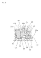
- a single contact-type mechanical seal (hereinafter referred to as "Prior Art 1") having a single sliding contact surface is a known example of a most commonly used conventional shaft-sealing device, as shown in FIG. 7 .
- This single contact-type mechanical seal has a configuration in which a rotational seal element 2 is provided in a state that allows movement in the axial direction and allows integral rotation with a rotating shaft 1, a stationary seal element 4 is provided in a non-rotating state in the seal case 3, and these seal elements slide in close contact with each other along mutually opposing end faces in accordance with the operation of a spring 5 that urges the rotational seal element 2 in the axial direction.
- the single contact-type mechanical seal has a problem in that the load that acts on a sliding section 6 is large, abrasion of the sliding section 6 is considerable, and the length of time in which a good seal performance can be maintained is short. Also, since the fluid pressure inside a machine is greater than the pressure outside a machine, the fluid inside the machine is liable to leak outside the machine.
- the double contact-type mechanical seal has a configuration in which two rotational seal elements 2 are provided facing outward in the axial direction in a state that allows integral rotation with a rotating shaft 1, two stationary seal elements 4 are provided in a non-rotating state in the seal case 3 and so as to face the two rotational seal elements 2, respectively, in a state that allows movement in the axial direction, and these seal elements slide in close contact with each other along mutually opposing end faces in accordance with the operation of a spring 5 that urges the stationary seal elements 4 in the axial direction.
- a seal fluid under higher pressure than the pressure of the fluid inside the machine is introduced into the area between the two sliding sections 6 in order to prevent fluid inside the machine from leaking out.
- the load that acts on the sliding sections 6 of the inner side of the machine is reduced by an amount equal to the pressure difference between the seal fluid and the fluid inside the machine, but the load that acts on the sliding sections 7 of the outer side of the machine is greater than that of Prior Art 1 because a seal fluid under higher pressure than the pressure of the fluid inside the machine is introduced into the area between the two sliding sections 6.
- a seal fluid under higher pressure than the pressure of the fluid inside the machine is introduced into the area between the two sliding sections 6.
- the tandem contact-type mechanical seal has a configuration in which two rotational seal elements 2 are provided in a state that allows integral rotation with a rotating shaft 1, two stationary seal elements 4 are provided in a non-rotating state in the seal case 3 and so as to face the two rotational seal elements 2 in the same direction in a state that allows movement in the axial direction, and these seal elements slide in close contact with each other along mutually opposing end faces in accordance with the operation of a spring 5 that urges the stationary seal elements 4 in the axial direction.
- the tandem contact-type mechanical seal is generally used for high-pressure applications or for recovering fluid inside the machine, and in the case of a high-pressure application, the fluid pressure inside the machine is divided between the seal of the inner side the machine and the seal of the outer side the machine, and the load that acts on each sliding section 6 is reduced.
- the fluid pressure inside the machine is set to be highest, there is a possibility that carbon dioxide will leak into the atmospheric air in the case that liquid carbon dioxide is used as the fluid inside the machine, and the effect of wear of the sliding sections 6 is dramatic in the case of long-term use. Carbon dioxide that has leaked between the seal of the inner side of the machine and the seal of the outer side of the machine must be recovered.
- the contact/contactless mechanism seal has a contact-type mechanical seal, in which a rotational seal element 2 is provided in a state that allows integral rotation with a rotating shaft 1 of the outer side of the machine, a stationary seal element 4 is provided in a non-rotating state in the seal case 3 and in a state that allows movement in the axial direction, and these seal elements slide in close contact with each other along mutually opposing end faces in accordance with the operation of a spring 5 that urges the stationary seal element 4 in the axial direction.
- the contact/contactless mechanism seal also has a contactless mechanical seal in which a rotational seal element 7 is provided in a state that allows integral rotation with a rotating shaft 1 of the inner side of the machine, a stationary seal element 8 is provided in a non-rotating state in the seal case 3 and in a state that allows movement in the axial direction, and the mutually opposing end faces are kept by dynamic pressure so as not to be in contact with each other due.
- the load that acts on the seal part is low and a large pressure reduction can be produced by the contactless mechanical seal even when the fluid pressure inside the machine is high, because the contactless mechanical seal is disposed in the inner side of the machine.
- the contactless mechanical seal disposed in the inner side of the machine has a configuration in which the rotational seal element 7 and the stationary seal element 8 are slightly set apart by the dynamic pressure against the pressing force of the spring 5, a very small gap is formed between the end faces of the rotational seal element 7 and the stationary seal element 8, and a seal function is obtained while fluid inside the machine leaks into the gap. Therefore, fluid inside the machine fills the space between the two mechanical seals and there is a possibility that a portion of the fluid will leak into the atmospheric air from the contact-type mechanical seal of the outer side of the machine. This is a critical problem in a device that handles supercritical carbon dioxide. Also, the carbon dioxide that fills the space between the mechanical seal of the inner side of the machine and the mechanical seal of the outer side of the machine must be recovered.
- Patent Document 1 Japanese Laid-open Patent Application No. 2002-98237
- Supercritical fluids have diffusive properties and are unique in that they have characteristics differing from those of ordinary gases and fluids. Therefore, a problem is presented in that the load that acts on the sliding sections in Prior Arts 1 and 2 is high and the time period in which good seal performance can be maintained is short in the case that the shaft-sealing devices for Prior Arts 1 through 4 described above are used in a machine that handles supercritical carbon dioxide. There is also a problem in Prior Arts 1, 3, and 4 in that carbon dioxide cannot be reliably prevented from leaking into the atmospheric air. Thus, conventional shaft-sealing devices cannot adequately maintain sealing performance over a long period of time, and supercritical carbon dioxide cannot be reliably prevented from leaking into the atmospheric air.
- An object of the present invention is to provide a shaft-sealing device that can reduce the load acting on the sliding section and extend service life, and can eliminate the work for recovering the fluid inside the machine without the fluid inside the machine leaking (into the atmospheric air).
- Another object of the present invention is to provide a shaft-sealing device that can accommodate a high-pressure fluid such as supercritical carbon dioxide that has diffusive properties.
- a first aspect of the shaft-sealing device of the present invention for achieving the objects described above is characterized in that seals are disposed in three stages in an axial direction between a seal case and a rotating shaft passed through an inner periphery of the seal case; among the seals of three stages, a first-stage seal on an inner side of the machine and a third-stage seal on an outer side of the machine have a contact-type mechanical seal structure in which a rotational seal element and a stationary seal element are in close sliding contact with each other; and, among the seals of three stages, an intermediate second stage seal has a contactless mechanical seal structure in which the rotational seal element and the stationary seal element are kept by dynamic pressure so as not to be in contact with each other.
- a second aspect of the present invention is the shaft-sealing device of the first aspect, characterized in that a seal fluid under higher pressure than the pressure of fluid inside the machine is supplied into a first annular space surrounded by that portion of the seal case extending from the first-stage seal to the second-stage seal.
- a third aspect of the present invention is the shaft-sealing device of the second aspect, characterized in that a pressure p2 of the seal liquid supplied into the first annular space is set in a range of p1 + 0.05 MPa ⁇ p2 ⁇ p1 + 0.5 MPa, wherein p2 is the pressure of the seal liquid supplied into the first annular space and p1 is the pressure of the fluid inside the machine.
- a pressure p2 of the seal liquid supplied into the first annular space is set in a range of p1 + 0.05 MPa ⁇ p2 ⁇ p1 + 0.5 MPa, wherein p2 is the pressure of the seal liquid supplied into the first annular space and p1 is the pressure of the fluid inside the machine.
- a fourth aspect of the present invention is the shaft-sealing device of the any of the first through third aspects, characterized in that coolant is circulated in a second annular space surrounded by the seal case of the outer periphery of the third-stage seal in communication with the inner peripheral space of the second-stage seal.
- a fifth aspect of the present invention is the shaft-sealing device of the fourth aspect, characterized in that a pressure p3 of the coolant is set in a range expressed by the relationship: atmospheric pressure ⁇ p3 ⁇ 0.2 MPa, where p3 is the pressure of the coolant.
- a sixth aspect of the present invention is the shaft-sealing device of any of the first to fifth aspects, characterized in that the seal fluid under higher pressure than the pressure of fluid inside the machine is supplied between the outside surface of the rotating shaft and the inside surface of a sleeve fitted and secured to the rotating shaft.
- a seventh aspect of the present invention is the shaft-sealing device of the sixth aspect, characterized in that a hole for conducting the seal fluid is provided to the first annular space and between the outside surface of the rotating shaft and the inside surface of the sleeve.
- An eighth aspect of the present invention is the shaft-sealing device of the seventh aspect, characterized in that an O-ring is disposed in a position so as to be between the conducting hole and the inner side of the machine, between the outside surface of the rotating shaft and the inside surface of the sleeve.
- the pressure of the elastomer part of an O-ring for sealing the space between the rotating shaft and the sleeve can be kept at a higher pressure than the fluid pressure inside the machine, and the fluid inside the machine can be prevented from permeating and leaking from the periphery of the rotating shaft to the exterior of the machine.
- the present invention has the following exceptional effects.
- FIG. 1 is a front cross-sectional view showing the entire shaft-sealing device of example 1.
- the numeral 100 refers to the housing of a shaft-sealing section in, e.g., a compressor, a boiler feed water pump, or a device that handles supercritical carbon dioxide;
- reference numeral 10 is a seal case mounted on the housing; and the left side of the drawing is the inside of the machine and the right side of the drawing is the outside of the machine (e.g., atmosphere).
- the seal case 10 has a plurality of metallic annular partitions 11 to 13 that is coupled together in the axial direction using a bolt and nut 14, and a rotating shaft 20 that rotates and drives a rotating member inside the machine is inserted through the internal periphery of the seal case so as to allow rotation about the axial center O of the rotating shaft.
- the space between the partitions 11 to 13 of the seal case 10 and the space between the partition 11 and the housing 100 are sealed by O-rings 15 to 18.
- a metal first sleeve 21 is mounted on the external peripheral surface of the rotating shaft 20 and the end section of the first sleeve of the inner side of the machine is locked using a key 28 to prevent rotation in relation to the rotating shaft 20, and a metal second sleeve 22 mounted on the external peripheral surface of the center section in the axial direction of the first sleeve 21 is locked using a key 29 to prevent rotation.
- the end sections of the first sleeve 21 and the second sleeve 22 of the outer side of the machine are secured by a collar 23 and a nut 24.
- the space between the rotating shaft 20 and the first sleeve 21 is sealed by an O-ring 25 near the inner side of the machine and by an O-ring 26 in the vicinity of the center section.
- the space between the first sleeve 21 and the second sleeve 22 is sealed by an O-ring 27 near the outer side of the machine.
- Three stage seals 30, 40, 50 i.e., a first-stage seal 30 of the inner side of the machine, an intermediate second-stage seal 40, and a third-stage seal 50 of the outer side of the machine are arranged in the axial direction in the peripheral space of the shaft between the seal case 10 and the rotating shaft 20.
- the first-stage seal 30 and the third-stage seal 50 are provided with a contact-type mechanical seal structure in which the seal sections of the rotational seal element and the stationary seal element slide in close contact with each other, and the second-stage seal 40 is provided with a contactless mechanical seal in which the seal sections of the rotational seal element and the stationary seal element are kept by dynamic pressure so as not to be in contact with each other.
- FIG. 2 is an enlarged partial sectional view of the first-stage seal 30 in FIG. 1 .
- the first-stage seal 30 of the inner side of the machine has a mating ring 31 for a rotational seal element on which the first sleeve 21 is fitted and in which the back surface is supported by a flange 21a of the first sleeve 21, and the mating ring is mounted on the flange 21a using a knock pin 32.
- a seal ring 33 for a stationary seal element is disposed opposite the mating ring 31, inserted into the first sleeve 21 and locked so as to prevent rotation via a knock pin 34, and is movably mounted on the seal case partition 11 in the axial direction.
- the back surface is pressed in the axial direction by a coil spring 35 provided to the seal case partition 11.
- the mating ring 31 and the seal ring 33 of the first-stage seal 30 are formed in an annular shape from, e.g., SiC or another hard material.
- the space between the mating ring 31 and the sleeve 21 is sealed using an O-ring 36, and the space between the seal ring 33 and the seal case partition 11 is sealed using and O-ring 37.
- the first-stage seal 30 having the configuration described above has a shaft-sealing function for sealing fluid inside the machine, the fluid being present in an inner peripheral space of the first-stage seal, wherein an end face 33a of the seal ring 33 makes sliding contact with the end face 31a of the mating ring 31 that rotates together with the rotating shaft 20, so as to seal with suitable surface pressure by the urging force of the coil spring 35.
- FIG. 3 is an enlarged partial sectional view of the second-stage seal 40 in FIG. 1 .
- the intermediate second-stage seal 40 has a mating ring 41 for a rotational seal element in which the back surface is supported by the flange 21a of the first sleeve 21 of the rotating shaft 20, and is mounted in a state in which the external periphery is engaged in the peripheral direction with the flange 21a via an engaging section 41b.
- a seal ring 42 for a stationary seal element is disposed in a state that allows movement in the axial direction and is locked so as to prevent rotation in a locking section 42b of the outer periphery by a retainer 12a mounted on the internal periphery of the seal case partition 12; and the back surface is pressed in the axial direction by a coil spring 43 via the retainer 12a and is thereby urged toward the mating ring 41.
- FIG. 4 is a view showing the dynamic pressure-generating grooves formed in the surface of the rotational seal element of the second-stage seal 40.
- a plurality of dynamic pressure-generating grooves 411, 412 that presents substantially L-shaped curve shapes mutually symmetrical in the peripheral direction is formed in alternating fashion in the peripheral direction in the end face 41a that acts as a non-contact seal surface in the mating ring 41 for a rotational seal element, as shown in FIG. 4 .
- the dynamic pressure-generating grooves 411, 412 are composed of portions 411a, 412a that extend in the radial direction from the external peripheral surface and portions 411b, 412b that extend in the peripheral direction.
- the portions 411b, 412b that extend in the peripheral direction have groove bottoms that form a sloped surface that gradually becomes shallow toward the end section of the side opposite from the portions 411a, 412a that extend in the radial direction.
- the dynamic pressure-generating grooves 411, 412 are formed to a micro depth on the order of microns by micromachining.
- the second-stage seal having the configuration described above is one in which the dynamic pressure-generating grooves 411, 412 of the end face 41a generate the dynamic pressure of the fluid (the fluid inside the machine) disposed between [the end face 41a] and an end face 42a of the seal ring 42 when the mating ring 41 rotates together with the rotating shaft 20.
- the dynamic pressure-generating grooves 411, 412 have a configuration in which the groove bottoms of the portions 411b, 412b that extend in the peripheral direction of the grooves are sloped surfaces that gradually become shallow toward the end sections. Therefore, the fluid inside the machine that is drawn into the grooves is compressed in accompaniment with relative movement with the end face 42a of the seal ring 42, and dynamic pressure is generated in the thrust direction.
- the dynamic pressure causes the seal ring 42 to slightly separate from the end face 41a of the mating ring 41 against the pressing force of the coil spring 43 toward the mating ring 41. Therefore, a shaft-sealing function is achieved in that a very small gap is formed between the end faces 41a, 42a of the mating ring 41 and the seal ring 42 while permitting slight leakage of the fluid inside the machine into the gap.
- FIG. 5 is an enlarged partial sectional view of the third-stage seal 50 in FIG. 1 .
- the third-stage seal 50 of the outer side of the machine has a mating ring 51 for a rotational seal element that is inserted into a second sleeve 22, has a back surface that is supported by a flange 22a of the second sleeve 22, and is mounted on the flange 22a using a knock pin 52.
- a seal ring 53 for a stationary seal element faces the mating ring 51, is inserted into the collar 23, is locked on the external peripheral section 53b of the seal ring so as to prevent rotation, and is mounted on the seal case partition 13 in a state that allows movement in the axial direction; and the back surface is pressed in the axial direction by a coil spring 54 provided to the seal case partition 13.
- the mating ring 51 and the seal ring 53 of the third-stage seal 50 are formed in an annular shape using SiC or another hard material.
- the space between the mating ring 51 and the second sleeve 22 is sealed using an O-ring 55.
- the space between the seal ring 53 and the seal case partition 13 is sealed using an O-ring 56.
- the third-stage seal 50 having the configuration described above has a shaft-sealing function for sealing fluid present in an outer peripheral space of the third-stage seal, wherein an end face 53a of the seal ring 53 makes sliding contact with the end face 51a of the mating ring 51 that rotates together with the rotating shaft 20, so as to seal with suitable surface pressure by the urging force of the coil spring 54.
- a first annular space 60 is formed between the inner periphery of the seal case partitions 11, 12 and the outer periphery of the first-stage seal 30 and the second-stage seal 40, and the first annular space 60 is in communication with a seal oil feed port 61 formed in the seal case partition 12 and a seal oil discharge port 62 formed in the seal case partition 11.
- An annular guide member 64 for actively introducing seal fluid to the sliding section of the end face 31a of the mating ring 31 and the end face 33a of the seal ring 33 is mounted on the seal case partition 11 and provided to the outer periphery of the first-stage seal 30 of the first annular space 60.
- a conducting hole 65 is provided between the first-stage seal 30 and the second-stage seal 40 of the first annular space 60 through the first sleeve 21 so as to act as a conduit between the outer surface of the shaft 20 and the inner surface of the first sleeve 21.
- the O-ring 25 is disposed between the conducting hole 65 and the inside of the machine, and the O-ring 26 is disposed between the conducting hole 65 and the outside of the machine.
- the seal oil supplied from the seal oil feed port 61 is an oil such as turbine oil, for example, and the pressure p2 of the seal oil is set to about p1 ⁇ p2 ⁇ p1 + 3 MPa, where p1 is the pressure of the fluid inside the machine.
- the pressure p2 of the seal oil is, to the extent possible, preferably set to be near the pressure p1 of the fluid inside the machine in order to reduce the load that acts on the sliding section of end face 31a of the mating ring 31 and the end face 33a of the seal ring 33, and is preferably set in a range of p1 + 0.05 MPa ⁇ p2 ⁇ p1 + 0.5 MPa so that the fluid inside the machine does not leak into the first annular space 60.
- seal oil at a higher pressure than the fluid inside the machine is supplied to the first annular space 60, whereby fluid inside the machine does not leak into the first annular space 60 from the sliding section of the end face 33a of the seal ring 33 and the end face 31a of the mating ring 31 of the first stage seal 30.
- the seal oil of the first annular space 60 is also supplied from the conducting hole 65 into the space between the outer surface of the shaft 20 and the inner surface of the first sleeve 21, is disposed between the inside of the machine and the conducting hole 65 between the outer surface of the shaft 20 and the inner surface of the first sleeve 21, and acts on the O-ring 25. Therefore, the fluid inside the machine does not leak from between the outer surface of the shaft 20 and the inner surface of the first sleeve 21.
- a second annular space 70 is formed between the inner periphery of the seal case partitions 12, 13 and the outer periphery of the third-stage seal 50 in communication with the inner peripheral space 66 of the second-stage seal 40, and the second annular space 70 is in communication with the coolant feed port 71 formed in the seal case partition 13 and a coolant discharge port 72 formed in the seal case partition 12.
- the coolant is used for recovering seal oil that has leaked from the first annular space 60 and for cooling various components constituting the third-stage seal 50.
- An annular guide member 73 for actively introducing coolant to the sliding section of the end face 51a of the mating ring 51 and the end face 53a of the seal ring 53 is mounted on the seal case partition 13 and provided to the outer periphery of the third-stage seal 50 of the second annular space 70.
- the coolant supplied from the coolant feed port 71 is, e.g., the same turbine oil as the seal fluid described above, and the pressure p3 of the coolant is expressed by the following relationship: atmospheric pressure ⁇ p3 ⁇ 0.2 MPa
- the shaft-sealing device configured as described above is mounted on the shaft-sealing section of the housing in, e.g., a compressor, a boiler feed water pump, or a device that handles supercritical carbon dioxide, as described above, and therefore seals high-pressure fluid inside the machine
- a portion of the high-pressure fluid inside the machine attempts to enter from the mating ring 31 and the seal ring 33 in the first-stage seal 30, which is a contact-type mechanical seal, into the first annular space 60 of the seal section, but the entry of the fluid inside the machine into the first annular space 60 is reliably blocked because seal fluid at higher pressure than the fluid inside the machine is supplied to the first annular space 60 and is at a higher pressure than the pressure p1 inside the machine.
- the pressure p2 of the first annular space 60 is set to a pressure that is slightly higher than the fluid pressure p1 inside the machine. Therefore, the load that acts on the sliding section of the seal ring 33 and the mating ring 31 is kept to a minimum, and the service life of the first-stage seal 30 can be extended.
- the second-stage seal 40 has a contactless mechanical seal structure; i.e., a structure in which the mating ring 41 rotates with a very small gap between the seal ring 42 due to the dynamic pressure generated by the dynamic pressure-generating grooves 411, 412 of the end face 41a, and the difference between the pressure p2 of the first annular space 60 and the pressure p3 of the second annular space 70 can be increased. As also occurs in such a case, the acting load is reduced, and abrasion and heat generated by sliding is substantially nonexistent.
- the supercritical pressure of carbon dioxide is 7.38 MPa, and the pressure of the fluid inside the machine is assumed to be 10 to 15 MPa.
- the pressure p2 of the first annular space 60 is also the same or greater.
- the pressure p3 of the second annular space 70 is a maximum of about 0.2 MPa, pressure difference in front and behind the second-stage seal 40 also reaches about 10 to 15 MPa.
- the mating ring 41 and the seal ring 42 in the second-stage seal 40 are not in contact with each other. Therefore, there is no acting load due to the high pressure difference and a stable shaft-sealing function can be obtained over a long period of time.
- the second-stage seal 40 is a contactless mechanical seal, a small amount of the seal oil supplied to the first annular space 60 leaks into the second annular space 70, but the third-stage seal having a contact-type mechanical structure is disposed on the outer side of the machine, and the seal oil is reliably sealed by the third-stage seal and does not leak to the atmospheric air. Also, since coolant is supplied from the coolant feed port 71 and is discharged from the coolant discharge port 72 in the second annular space 70, seal oil that has leaked into the second annular space 70 is reliably recovered.
- the pressure p3 of the second annular space 70 is set to be slightly higher than the pressure outside the machine (e.g., atmospheric pressure). Therefore, the load that acts on the sliding section of the mating ring 51 and the seal ring 53 of the third-stage seal, which has a contact-type mechanical seal structure, can be kept to a minimum and the service life of the third-stage seal 50 can be extended.
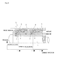
- FIG. 6 is a front cross-sectional view showing the entire shaft-sealing device of the present example 2.
- the shaft-sealing device of the present example 2 has the same basic structure as example 1, and in FIG. 6 , the same reference numerals as FIG. 1 refer to the same members as those in FIG. 1 .
- the portions that are different from example 1 are mainly described below.
- the three stage seals 30, 40, 50 i.e., the first-stage seal 30 of the inner side of the machine, the intermediate second-stage seal 40, and the third-stage seal 50 of the outer side of the machine are arranged in the axial direction in the peripheral space of the shaft between the seal case 10 and the rotating shaft 20.
- the first-stage seal 30 and the third-stage seal 50 have a contact-type mechanical seal structure in which the seal sections of the rotational seal element and the stationary seal element slide in close contact with each other; and the second-stage seal 40 has a contactless mechanical seal structure in which the seal sections of the rotational seal element and the stationary seal element are in a non-contact state with each other due to dynamic pressure.
- the shaft 20 is relatively narrow and the shaft-sealing device is designed to be secured by a nut 24 disposed in the inner side of the machine.
- the mating ring 31 of the first-stage seal 30 and the mating ring 51 of the third-stage seal 50 are designed to be directly fitted and mounted onto the shaft 20.
- the metal sleeve mounted on the external peripheral surface of the rotating shaft 20 has a structure in which a sleeve 21A of the inner side of the machine of the first sleeve 21 and a center sleeve 21B are arranged so as to sandwich the mating ring 31 of the first-stage seal 30; and the second sleeve 22 is arranged between the center sleeve 21B and the mating ring 51 of the third-stage seal 50.
- a step section is formed in the shaft 20 so as to be in contact with the right end of the mating ring 51 of the third-stage seal 50, and the second sleeve 22 is mounted on the outer surface of the shaft 20 so as to be in contact with the left end of the mating ring 51.
- the center sleeve 21B of the first sleeve 21 is mounted on the outer surface of the shaft 20 so as to be in contact with the left end of the second sleeve 22 and the right end of the mating ring 31 of the first-stage seal 30, and the sleeve 21A of the inner side of the machine of the first sleeve 21 is mounted on the outer surface of the shaft 20 so as to be in contact with the left end of the mating ring 31 of the first-stage seal 30.
- the assembly is tightened in the axial direction using a nut 24 from the left end of the sleeve 21A of the inner side of the machine of the first sleeve 21.
- the space between the rotating shaft 20 and the first sleeve 21 is sealed by the O-ring 25 positioned and provided on the contact surfaces of the right end of the first sleeve 21 and the left end of the mating ring 31 of the first-stage seal 30, and the space between the rotating shaft 20 and the first sleeve 21A is sealed by the O-ring 27.
- the high-pressure seal oil supplied to the first annular space 60 enters the space between the outer surface of the shaft and the inner surface of the sleeves 21, 21A from the space between the left end of the first sleeve 21A and the right end of the mating ring 31 of the first-stage seal 30.
- the O-ring 25 and the O-ring 27 keep the pressure higher than the pressure of the fluid inside the machine. Accordingly, the fluid inside the machine having dispersive properties in similar fashion to supercritical carbon dioxide can be reliably prevented from entering into the space between the outer surface of the shaft 20 and the inner surface of the sleeves 21, 21A and leaking to the exterior of the machine.
- the shaft-sealing device of example 2 shown in FIG. 6 has a structure in which the mating ring 31 of the first-stage seal 30 and the mating ring 51 of the third-stage seal 50 are directly mounted on the rotating shaft 20 rather than being mounted on a sleeve. Therefore, the shape of the sleeve can be simplified, the space between the sleeve and the mating ring 31 and the mating ring 51 is not required to be sealed, and the O-rings can be omitted.
Landscapes
- Engineering & Computer Science (AREA)
- General Engineering & Computer Science (AREA)
- Mechanical Engineering (AREA)
- Mechanical Sealing (AREA)
Applications Claiming Priority (2)
| Application Number | Priority Date | Filing Date | Title |
|---|---|---|---|
| JP2008043451 | 2008-02-25 | ||
| PCT/JP2009/051310 WO2009107440A1 (fr) | 2008-02-25 | 2009-01-28 | Dispositif d'étanchéité d'arbre |
Publications (3)
| Publication Number | Publication Date |
|---|---|
| EP2246597A1 true EP2246597A1 (fr) | 2010-11-03 |
| EP2246597A4 EP2246597A4 (fr) | 2016-11-23 |
| EP2246597B1 EP2246597B1 (fr) | 2018-04-04 |
Family
ID=41015846
Family Applications (1)
| Application Number | Title | Priority Date | Filing Date |
|---|---|---|---|
| EP09715649.1A Active EP2246597B1 (fr) | 2008-02-25 | 2009-01-28 | Dispositif d'étanchéité d'arbre |
Country Status (4)
| Country | Link |
|---|---|
| US (1) | US8186688B2 (fr) |
| EP (1) | EP2246597B1 (fr) |
| JP (1) | JP5291083B2 (fr) |
| WO (1) | WO2009107440A1 (fr) |
Cited By (5)
| Publication number | Priority date | Publication date | Assignee | Title |
|---|---|---|---|---|
| CN102072322A (zh) * | 2011-01-31 | 2011-05-25 | 江苏金鹰流体机械有限公司 | 双端面组合式密封装置 |
| CN102147014A (zh) * | 2011-03-23 | 2011-08-10 | 苏州瑞维液压科技有限公司 | 高压旋转密封装置 |
| CN102619984A (zh) * | 2012-03-29 | 2012-08-01 | 大连华阳光大密封有限公司 | 一种用于高压工况的机械密封装置 |
| CN102678932A (zh) * | 2012-04-27 | 2012-09-19 | 大连华阳光大密封有限公司 | 一种不带辅助系统的双端面机械密封 |
| CN106605089A (zh) * | 2014-09-24 | 2017-04-26 | 伊格尔工业股份有限公司 | 机械密封件 |
Families Citing this family (16)
| Publication number | Priority date | Publication date | Assignee | Title |
|---|---|---|---|---|
| JP5478290B2 (ja) * | 2010-02-12 | 2014-04-23 | 株式会社荏原製作所 | タンデムメカニカルシール |
| DE102010024289A1 (de) * | 2010-04-23 | 2011-10-27 | Carl Freudenberg Kg | Gleitringdichtung |
| JP5535749B2 (ja) * | 2010-04-28 | 2014-07-02 | 三菱重工業株式会社 | ドライガスシール構造 |
| JP5608464B2 (ja) * | 2010-08-04 | 2014-10-15 | 日本ピラー工業株式会社 | ダブルシール構造 |
| AU2011372779B2 (en) * | 2011-10-27 | 2014-04-24 | Mitsubishi Heavy Industries, Ltd. | Dry gas seal structure |
| CN102494136B (zh) * | 2011-11-30 | 2015-02-04 | 广州广船国际股份有限公司 | 一种掘进设备的主轴密封结构 |
| CN203348544U (zh) * | 2013-05-21 | 2013-12-18 | 自贡市永宏密封件制造有限公司 | 一种双端面密封装置 |
| CN103267131B (zh) * | 2013-06-02 | 2016-05-11 | 西华大学 | 非接触式机械密封装置 |
| WO2015095847A1 (fr) * | 2013-12-20 | 2015-06-25 | International Pump Solutions, Inc. | Joint mécanique double pour pompe centrifuge |
| DE202014103019U1 (de) * | 2014-07-02 | 2015-10-08 | Brinkmann Pumpen K.H. Brinkmann Gmbh & Co. Kg | Dichtungsanordnung an einer Pumpenwelle |
| CN104455456A (zh) * | 2014-11-05 | 2015-03-25 | 中国航空动力机械研究所 | 流体动力的密封装置 |
| DE102014226429A1 (de) * | 2014-12-18 | 2016-06-23 | Eagleburgmann Germany Gmbh & Co. Kg | Wellendichtungsanordnung einer Fluidmaschine sowie Verfahren zur Abdichtung einer Welle einer Fluidmaschine |
| US10563530B2 (en) * | 2015-10-12 | 2020-02-18 | General Electric Company | Intershaft seal with dual opposing carbon seal rings |
| CN107676293A (zh) * | 2017-09-19 | 2018-02-09 | 江苏大学 | 一种高温高压多级泵用串联式机械密封 |
| US11719114B2 (en) * | 2018-09-19 | 2023-08-08 | Raytheon Technologies Corporation | Low friction carbon—carbon seal assembly |
| JP7229096B2 (ja) * | 2019-05-17 | 2023-02-27 | 日本ピラー工業株式会社 | ロータリジョイント |
Family Cites Families (8)
| Publication number | Priority date | Publication date | Assignee | Title |
|---|---|---|---|---|
| US3179422A (en) | 1962-04-10 | 1965-04-20 | Ingersoll Rand Co | Self-compensating shaft seal |
| US3813103A (en) * | 1972-04-12 | 1974-05-28 | Borg Warner | Mechanical seal with improved leakage control |
| US4964646A (en) * | 1989-03-27 | 1990-10-23 | Bw/Ip International, Inc. | Fluid handling apparatus with shaft sleeve and extension |
| US5217233A (en) * | 1989-10-30 | 1993-06-08 | John Crane Inc. | Spiral groove seal system for sealing a high pressure gas |
| JPH0769018B2 (ja) * | 1992-02-26 | 1995-07-26 | 日本ピラー工業株式会社 | 軸封装置 |
| US5421593A (en) * | 1993-08-05 | 1995-06-06 | Nippon Pillar Packing Co., Ltd. | Shaft seal device |
| JP4537558B2 (ja) | 2000-09-21 | 2010-09-01 | イーグル工業株式会社 | 軸封装置 |
| JP4763920B2 (ja) * | 2001-06-21 | 2011-08-31 | イーグル工業株式会社 | 多段軸封装置 |
-
2009
- 2009-01-28 JP JP2010500616A patent/JP5291083B2/ja active Active
- 2009-01-28 EP EP09715649.1A patent/EP2246597B1/fr active Active
- 2009-01-28 WO PCT/JP2009/051310 patent/WO2009107440A1/fr active Application Filing
- 2009-01-28 US US12/667,214 patent/US8186688B2/en active Active
Non-Patent Citations (1)
| Title |
|---|
| See references of WO2009107440A1 * |
Cited By (7)
| Publication number | Priority date | Publication date | Assignee | Title |
|---|---|---|---|---|
| CN102072322A (zh) * | 2011-01-31 | 2011-05-25 | 江苏金鹰流体机械有限公司 | 双端面组合式密封装置 |
| CN102147014A (zh) * | 2011-03-23 | 2011-08-10 | 苏州瑞维液压科技有限公司 | 高压旋转密封装置 |
| CN102619984A (zh) * | 2012-03-29 | 2012-08-01 | 大连华阳光大密封有限公司 | 一种用于高压工况的机械密封装置 |
| CN102678932A (zh) * | 2012-04-27 | 2012-09-19 | 大连华阳光大密封有限公司 | 一种不带辅助系统的双端面机械密封 |
| CN102678932B (zh) * | 2012-04-27 | 2014-09-24 | 大连华阳密封股份有限公司 | 一种不带辅助系统的双端面机械密封 |
| CN106605089A (zh) * | 2014-09-24 | 2017-04-26 | 伊格尔工业股份有限公司 | 机械密封件 |
| CN106605089B (zh) * | 2014-09-24 | 2018-07-06 | 伊格尔工业股份有限公司 | 机械密封件 |
Also Published As
| Publication number | Publication date |
|---|---|
| JPWO2009107440A1 (ja) | 2011-06-30 |
| WO2009107440A1 (fr) | 2009-09-03 |
| JP5291083B2 (ja) | 2013-09-18 |
| US20100327533A1 (en) | 2010-12-30 |
| EP2246597B1 (fr) | 2018-04-04 |
| US8186688B2 (en) | 2012-05-29 |
| EP2246597A4 (fr) | 2016-11-23 |
Similar Documents
| Publication | Publication Date | Title |
|---|---|---|
| EP2246597B1 (fr) | Dispositif d'étanchéité d'arbre | |
| EP3816488B1 (fr) | Bague d'étanchéité | |
| US8356819B2 (en) | Low and reverse pressure application hydrodynamic pressurizing seals | |
| US9518473B2 (en) | Shaft seal insert | |
| US10605105B2 (en) | Bi-directional shaft seal | |
| US10907684B2 (en) | Sliding part | |
| US20150184531A1 (en) | Gasket device for the bearing of a turbomachine, comprising two elastic seals | |
| US8215894B2 (en) | Dual configuration seal assembly for a rotational assembly | |
| JP2009250378A (ja) | 液体用のメカニカルシール装置 | |
| JP2018503038A (ja) | 流体機械の軸封装置及び流体機械の軸の封止方法 | |
| ITCO20090071A1 (it) | Tenuta che si puo' abradere con spostamento assiale | |
| CA2210609C (fr) | Joint d'etancheite a soufflet a capacite de fonctionnement en pression inverse | |
| US7004473B2 (en) | Mechanical seal device | |
| JP2009250170A (ja) | スクリュ流体機械 | |
| US9791047B2 (en) | Magnetic seal system with internal cooling | |
| US20160090990A1 (en) | Arrangement having a seal | |
| AU2015270310B2 (en) | High-pressure rotary seal-plug assembly with expandable continuous ring | |
| US9488188B2 (en) | Compressor | |
| EP3015748A1 (fr) | Dispositif d'étanchéité | |
| US11118594B2 (en) | Seal apparatus for a turbomachine casing | |
| EP3255323A1 (fr) | Garniture mécanique | |
| CN108413040A (zh) | 唇形机械密封装置 | |
| WO2016140056A1 (fr) | Bague d'étanchéité | |
| US20060188381A1 (en) | Seal assembly for hydraulic pump output shaft | |
| Gruenewald et al. | Recent progress in compressor sealing |
Legal Events
| Date | Code | Title | Description |
|---|---|---|---|
| PUAI | Public reference made under article 153(3) epc to a published international application that has entered the european phase |
Free format text: ORIGINAL CODE: 0009012 |
|
| 17P | Request for examination filed |
Effective date: 20100108 |
|
| AK | Designated contracting states |
Kind code of ref document: A1 Designated state(s): AT BE BG CH CY CZ DE DK EE ES FI FR GB GR HR HU IE IS IT LI LT LU LV MC MK MT NL NO PL PT RO SE SI SK TR |
|
| AX | Request for extension of the european patent |
Extension state: AL BA RS |
|
| DAX | Request for extension of the european patent (deleted) | ||
| RA4 | Supplementary search report drawn up and despatched (corrected) |
Effective date: 20161025 |
|
| RIC1 | Information provided on ipc code assigned before grant |
Ipc: F16J 15/34 20060101AFI20161019BHEP Ipc: F16J 15/00 20060101ALI20161019BHEP Ipc: F16J 15/40 20060101ALI20161019BHEP |
|
| RIC1 | Information provided on ipc code assigned before grant |
Ipc: F16J 15/40 20060101ALI20170822BHEP Ipc: F16J 15/00 20060101ALI20170822BHEP Ipc: F16J 15/34 20060101AFI20170822BHEP |
|
| GRAP | Despatch of communication of intention to grant a patent |
Free format text: ORIGINAL CODE: EPIDOSNIGR1 |
|
| STAA | Information on the status of an ep patent application or granted ep patent |
Free format text: STATUS: GRANT OF PATENT IS INTENDED |
|
| INTG | Intention to grant announced |
Effective date: 20171027 |
|
| GRAS | Grant fee paid |
Free format text: ORIGINAL CODE: EPIDOSNIGR3 |
|
| GRAA | (expected) grant |
Free format text: ORIGINAL CODE: 0009210 |
|
| STAA | Information on the status of an ep patent application or granted ep patent |
Free format text: STATUS: THE PATENT HAS BEEN GRANTED |
|
| AK | Designated contracting states |
Kind code of ref document: B1 Designated state(s): AT BE BG CH CY CZ DE DK EE ES FI FR GB GR HR HU IE IS IT LI LT LU LV MC MK MT NL NO PL PT RO SE SI SK TR |
|
| REG | Reference to a national code |
Ref country code: GB Ref legal event code: FG4D |
|
| REG | Reference to a national code |
Ref country code: CH Ref legal event code: EP |
|
| REG | Reference to a national code |
Ref country code: AT Ref legal event code: REF Ref document number: 985942 Country of ref document: AT Kind code of ref document: T Effective date: 20180415 |
|
| REG | Reference to a national code |
Ref country code: DE Ref legal event code: R096 Ref document number: 602009051605 Country of ref document: DE |
|
| REG | Reference to a national code |
Ref country code: IE Ref legal event code: FG4D |
|
| REG | Reference to a national code |
Ref country code: NL Ref legal event code: MP Effective date: 20180404 |
|
| REG | Reference to a national code |
Ref country code: LT Ref legal event code: MG4D |
|
| PG25 | Lapsed in a contracting state [announced via postgrant information from national office to epo] |
Ref country code: NL Free format text: LAPSE BECAUSE OF FAILURE TO SUBMIT A TRANSLATION OF THE DESCRIPTION OR TO PAY THE FEE WITHIN THE PRESCRIBED TIME-LIMIT Effective date: 20180404 |
|
| PG25 | Lapsed in a contracting state [announced via postgrant information from national office to epo] |
Ref country code: ES Free format text: LAPSE BECAUSE OF FAILURE TO SUBMIT A TRANSLATION OF THE DESCRIPTION OR TO PAY THE FEE WITHIN THE PRESCRIBED TIME-LIMIT Effective date: 20180404 Ref country code: FI Free format text: LAPSE BECAUSE OF FAILURE TO SUBMIT A TRANSLATION OF THE DESCRIPTION OR TO PAY THE FEE WITHIN THE PRESCRIBED TIME-LIMIT Effective date: 20180404 Ref country code: NO Free format text: LAPSE BECAUSE OF FAILURE TO SUBMIT A TRANSLATION OF THE DESCRIPTION OR TO PAY THE FEE WITHIN THE PRESCRIBED TIME-LIMIT Effective date: 20180704 Ref country code: SE Free format text: LAPSE BECAUSE OF FAILURE TO SUBMIT A TRANSLATION OF THE DESCRIPTION OR TO PAY THE FEE WITHIN THE PRESCRIBED TIME-LIMIT Effective date: 20180404 Ref country code: PL Free format text: LAPSE BECAUSE OF FAILURE TO SUBMIT A TRANSLATION OF THE DESCRIPTION OR TO PAY THE FEE WITHIN THE PRESCRIBED TIME-LIMIT Effective date: 20180404 Ref country code: LT Free format text: LAPSE BECAUSE OF FAILURE TO SUBMIT A TRANSLATION OF THE DESCRIPTION OR TO PAY THE FEE WITHIN THE PRESCRIBED TIME-LIMIT Effective date: 20180404 Ref country code: BG Free format text: LAPSE BECAUSE OF FAILURE TO SUBMIT A TRANSLATION OF THE DESCRIPTION OR TO PAY THE FEE WITHIN THE PRESCRIBED TIME-LIMIT Effective date: 20180704 |
|
| PG25 | Lapsed in a contracting state [announced via postgrant information from national office to epo] |
Ref country code: GR Free format text: LAPSE BECAUSE OF FAILURE TO SUBMIT A TRANSLATION OF THE DESCRIPTION OR TO PAY THE FEE WITHIN THE PRESCRIBED TIME-LIMIT Effective date: 20180705 Ref country code: HR Free format text: LAPSE BECAUSE OF FAILURE TO SUBMIT A TRANSLATION OF THE DESCRIPTION OR TO PAY THE FEE WITHIN THE PRESCRIBED TIME-LIMIT Effective date: 20180404 Ref country code: LV Free format text: LAPSE BECAUSE OF FAILURE TO SUBMIT A TRANSLATION OF THE DESCRIPTION OR TO PAY THE FEE WITHIN THE PRESCRIBED TIME-LIMIT Effective date: 20180404 |
|
| REG | Reference to a national code |
Ref country code: AT Ref legal event code: MK05 Ref document number: 985942 Country of ref document: AT Kind code of ref document: T Effective date: 20180404 |
|
| PG25 | Lapsed in a contracting state [announced via postgrant information from national office to epo] |
Ref country code: PT Free format text: LAPSE BECAUSE OF FAILURE TO SUBMIT A TRANSLATION OF THE DESCRIPTION OR TO PAY THE FEE WITHIN THE PRESCRIBED TIME-LIMIT Effective date: 20180806 |
|
| REG | Reference to a national code |
Ref country code: DE Ref legal event code: R097 Ref document number: 602009051605 Country of ref document: DE |
|
| PG25 | Lapsed in a contracting state [announced via postgrant information from national office to epo] |
Ref country code: RO Free format text: LAPSE BECAUSE OF FAILURE TO SUBMIT A TRANSLATION OF THE DESCRIPTION OR TO PAY THE FEE WITHIN THE PRESCRIBED TIME-LIMIT Effective date: 20180404 Ref country code: SK Free format text: LAPSE BECAUSE OF FAILURE TO SUBMIT A TRANSLATION OF THE DESCRIPTION OR TO PAY THE FEE WITHIN THE PRESCRIBED TIME-LIMIT Effective date: 20180404 Ref country code: CZ Free format text: LAPSE BECAUSE OF FAILURE TO SUBMIT A TRANSLATION OF THE DESCRIPTION OR TO PAY THE FEE WITHIN THE PRESCRIBED TIME-LIMIT Effective date: 20180404 Ref country code: EE Free format text: LAPSE BECAUSE OF FAILURE TO SUBMIT A TRANSLATION OF THE DESCRIPTION OR TO PAY THE FEE WITHIN THE PRESCRIBED TIME-LIMIT Effective date: 20180404 Ref country code: AT Free format text: LAPSE BECAUSE OF FAILURE TO SUBMIT A TRANSLATION OF THE DESCRIPTION OR TO PAY THE FEE WITHIN THE PRESCRIBED TIME-LIMIT Effective date: 20180404 Ref country code: DK Free format text: LAPSE BECAUSE OF FAILURE TO SUBMIT A TRANSLATION OF THE DESCRIPTION OR TO PAY THE FEE WITHIN THE PRESCRIBED TIME-LIMIT Effective date: 20180404 |
|
| PLBE | No opposition filed within time limit |
Free format text: ORIGINAL CODE: 0009261 |
|
| STAA | Information on the status of an ep patent application or granted ep patent |
Free format text: STATUS: NO OPPOSITION FILED WITHIN TIME LIMIT |
|
| PG25 | Lapsed in a contracting state [announced via postgrant information from national office to epo] |
Ref country code: IT Free format text: LAPSE BECAUSE OF FAILURE TO SUBMIT A TRANSLATION OF THE DESCRIPTION OR TO PAY THE FEE WITHIN THE PRESCRIBED TIME-LIMIT Effective date: 20180404 |
|
| 26N | No opposition filed |
Effective date: 20190107 |
|
| PG25 | Lapsed in a contracting state [announced via postgrant information from national office to epo] |
Ref country code: SI Free format text: LAPSE BECAUSE OF FAILURE TO SUBMIT A TRANSLATION OF THE DESCRIPTION OR TO PAY THE FEE WITHIN THE PRESCRIBED TIME-LIMIT Effective date: 20180404 |
|
| PG25 | Lapsed in a contracting state [announced via postgrant information from national office to epo] |
Ref country code: MC Free format text: LAPSE BECAUSE OF FAILURE TO SUBMIT A TRANSLATION OF THE DESCRIPTION OR TO PAY THE FEE WITHIN THE PRESCRIBED TIME-LIMIT Effective date: 20180404 |
|
| REG | Reference to a national code |
Ref country code: CH Ref legal event code: PL |
|
| GBPC | Gb: european patent ceased through non-payment of renewal fee |
Effective date: 20190128 |
|
| PG25 | Lapsed in a contracting state [announced via postgrant information from national office to epo] |
Ref country code: LU Free format text: LAPSE BECAUSE OF NON-PAYMENT OF DUE FEES Effective date: 20190128 |
|
| REG | Reference to a national code |
Ref country code: BE Ref legal event code: MM Effective date: 20190131 |
|
| REG | Reference to a national code |
Ref country code: IE Ref legal event code: MM4A |
|
| PG25 | Lapsed in a contracting state [announced via postgrant information from national office to epo] |
Ref country code: FR Free format text: LAPSE BECAUSE OF NON-PAYMENT OF DUE FEES Effective date: 20190131 |
|
| PG25 | Lapsed in a contracting state [announced via postgrant information from national office to epo] |
Ref country code: BE Free format text: LAPSE BECAUSE OF NON-PAYMENT OF DUE FEES Effective date: 20190131 |
|
| PG25 | Lapsed in a contracting state [announced via postgrant information from national office to epo] |
Ref country code: GB Free format text: LAPSE BECAUSE OF NON-PAYMENT OF DUE FEES Effective date: 20190128 Ref country code: CH Free format text: LAPSE BECAUSE OF NON-PAYMENT OF DUE FEES Effective date: 20190131 Ref country code: LI Free format text: LAPSE BECAUSE OF NON-PAYMENT OF DUE FEES Effective date: 20190131 |
|
| PG25 | Lapsed in a contracting state [announced via postgrant information from national office to epo] |
Ref country code: IE Free format text: LAPSE BECAUSE OF NON-PAYMENT OF DUE FEES Effective date: 20190128 |
|
| PG25 | Lapsed in a contracting state [announced via postgrant information from national office to epo] |
Ref country code: TR Free format text: LAPSE BECAUSE OF FAILURE TO SUBMIT A TRANSLATION OF THE DESCRIPTION OR TO PAY THE FEE WITHIN THE PRESCRIBED TIME-LIMIT Effective date: 20180404 |
|
| PG25 | Lapsed in a contracting state [announced via postgrant information from national office to epo] |
Ref country code: MT Free format text: LAPSE BECAUSE OF NON-PAYMENT OF DUE FEES Effective date: 20190128 |
|
| PG25 | Lapsed in a contracting state [announced via postgrant information from national office to epo] |
Ref country code: CY Free format text: LAPSE BECAUSE OF FAILURE TO SUBMIT A TRANSLATION OF THE DESCRIPTION OR TO PAY THE FEE WITHIN THE PRESCRIBED TIME-LIMIT Effective date: 20180404 |
|
| PG25 | Lapsed in a contracting state [announced via postgrant information from national office to epo] |
Ref country code: IS Free format text: LAPSE BECAUSE OF FAILURE TO SUBMIT A TRANSLATION OF THE DESCRIPTION OR TO PAY THE FEE WITHIN THE PRESCRIBED TIME-LIMIT Effective date: 20180804 |
|
| PG25 | Lapsed in a contracting state [announced via postgrant information from national office to epo] |
Ref country code: HU Free format text: LAPSE BECAUSE OF FAILURE TO SUBMIT A TRANSLATION OF THE DESCRIPTION OR TO PAY THE FEE WITHIN THE PRESCRIBED TIME-LIMIT; INVALID AB INITIO Effective date: 20090128 |
|
| PG25 | Lapsed in a contracting state [announced via postgrant information from national office to epo] |
Ref country code: MK Free format text: LAPSE BECAUSE OF FAILURE TO SUBMIT A TRANSLATION OF THE DESCRIPTION OR TO PAY THE FEE WITHIN THE PRESCRIBED TIME-LIMIT Effective date: 20180404 |
|
| PGFP | Annual fee paid to national office [announced via postgrant information from national office to epo] |
Ref country code: DE Payment date: 20231205 Year of fee payment: 16 |