EP2246584A1 - Clutch - Google Patents
Clutch Download PDFInfo
- Publication number
- EP2246584A1 EP2246584A1 EP09005850A EP09005850A EP2246584A1 EP 2246584 A1 EP2246584 A1 EP 2246584A1 EP 09005850 A EP09005850 A EP 09005850A EP 09005850 A EP09005850 A EP 09005850A EP 2246584 A1 EP2246584 A1 EP 2246584A1
- Authority
- EP
- European Patent Office
- Prior art keywords
- clutch
- width
- drive
- crowns
- spring
- Prior art date
- Legal status (The legal status is an assumption and is not a legal conclusion. Google has not performed a legal analysis and makes no representation as to the accuracy of the status listed.)
- Granted
Links
Images

Classifications
-
- F—MECHANICAL ENGINEERING; LIGHTING; HEATING; WEAPONS; BLASTING
- F16—ENGINEERING ELEMENTS AND UNITS; GENERAL MEASURES FOR PRODUCING AND MAINTAINING EFFECTIVE FUNCTIONING OF MACHINES OR INSTALLATIONS; THERMAL INSULATION IN GENERAL
- F16D—COUPLINGS FOR TRANSMITTING ROTATION; CLUTCHES; BRAKES
- F16D13/00—Friction clutches
- F16D13/58—Details
- F16D13/60—Clutching elements
- F16D13/64—Clutch-plates; Clutch-lamellae
- F16D13/68—Attachments of plates or lamellae to their supports
- F16D13/683—Attachments of plates or lamellae to their supports for clutches with multiple lamellae
Definitions
- the present invention relates to a clutch, in particular to a hydraulic double clutch for a transmission of a motor, according the preamble part of claim 1.
- This clutch comprises a drive drum having a plurality of circumferentially disposed connecting crowns and a drive plate having a plurality of circumferentially disposed slots into which the connecting crowns extend to provide a drive connection between the drive drum and the drive plate.
- the drive plate and drive drum can be connected also in different ways such as a spline connection.
- the object is solved by providing a plurality of springs connected to the drive plate and abutting against the non-driven side of the crowns in the drive drum.
- the springs By connecting the drive drum crowns inside the slots, the springs get preloaded. This preload force is high enough to generate a torque which is at least as high as the negative torque peaks created by the driveline vibrations. This way the driving flanks of the slot-crown connection remain always in contact and noise is avoided.
- the springs are integrated in the drive plate as elastic fingers which are manufactured in the same process steps as for stamping or punching the drive plate.
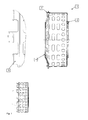
- Fig. 1 shows cross sectional view of a drive plate 4 and a drive drum 2 of a clutch 1 that is not depicted in its entirety but comprises, of course, all other components of a clutch as well.
- the drive plate 4 is connected to the motor (not shown) whilst the drive drum 2 is connected to the clutch input.
- the drive plate 4 is connected to the drive drum 2 by engaging a plurality of connecting crowns 3 disposed circumferentially on the drive drum 2 with circumferentially disposed associated slots 5, 6 having a predetermined width which are provided on the drive plate 4.
- Fig. 2 shows a perspective view of the drive plate 4 of the clutch 1 including, in this case, three circumferentially disposed springs 7 and associated slots 5. As can be seen from Fig. 2 these springs 7 are circumferentially disposed at intervals of 120° on the drive plate 4 next to the slots 5 and follow the contour of the cup-shaped drive plate 4. When the connecting crowns 3 of the drive drum 2 are inserted into the slots 5, 6 of the drive plate 4 to provide a drive connection, the springs 7 are abutting firmly against the side walls of the associated crowns 3. By this spring-forced abutment a movement of the connecting crowns 3 in the slots 5, 6 and the generation of the rattling noise is prevented.
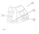
- Fig. 3 shows an enlarged partial view of the drive plate 4 and one of its springs 7 according to the present invention taking the form of a spring finger connected with the drive plate 4.
- the predetermined width W2 of the slot 5 with spring 7 is set smaller than the width W1 of the crowns 3 of Fig. 1 .
- the width W3 of all the slots 6 without a spring ( Fig. 2 ) is slightly larger than the width W1 of the crowns 3.
- this spring 7 can be an integral part of the drive plate 4, e. g. being punched out of the drive plate 4, and being disposed between two neighboring slots 5 and 6 (the latter not shown on the figures.).
Abstract
Description
- The present invention relates to a clutch, in particular to a hydraulic double clutch for a transmission of a motor, according the preamble part of
claim 1. - This clutch comprises a drive drum having a plurality of circumferentially disposed connecting crowns and a drive plate having a plurality of circumferentially disposed slots into which the connecting crowns extend to provide a drive connection between the drive drum and the drive plate.
- The drive plate and drive drum can be connected also in different ways such as a spline connection.
- However, due to torque fluctuations in the drive chain during torque transmission a rattling noise is generated by a relative movement of these crowns within the slots having a width being greater than the width of the connecting crowns. This rattle movement generated by the play between crowns and slots also results in a deteriorated durability of the connection arrangement between drive plate and drive drum.
- It is, therefore, an object underlying the present invention to provide a clutch according to the preamble part of
claim 1 that is able to reduce the generation of noise as far as possible. - The solution of this object is achieved by the features of
claim 1. - According to the present invention the object is solved by providing a plurality of springs connected to the drive plate and abutting against the non-driven side of the crowns in the drive drum. By connecting the drive drum crowns inside the slots, the springs get preloaded. This preload force is high enough to generate a torque which is at least as high as the negative torque peaks created by the driveline vibrations. This way the driving flanks of the slot-crown connection remain always in contact and noise is avoided.
- In a preferred embodiment the springs are integrated in the drive plate as elastic fingers which are manufactured in the same process steps as for stamping or punching the drive plate. By integrating these fingers in the relatively big drive plate, these fingers can be made quite long.
- The bending of the fingers is limited because the tangential relative movement of the crowns inside the slots is restricted by the play between the crowns and the slots. These both factors, namely the long springs and the small tangential movement, keep the mechanical stress in the finger material below critical values.
- The dependent claims contain advantageous embodiments of the present invention.
- Further features and advantages of the present invention will become apparent from the following description of a preferred embodiment with reference to the appended drawings, wherein
-
Fig. 1 shows a cross-sectional view of a drive plate and a drive drum of a clutch according to the present invention, -
Fig. 2 shows a perspective view of the drive plate of the clutch including three circumferentially disposed spring devices, and -
Fig. 3 shows an enlarged partial perspective view of the drive plate ofFig. 2 according to the present invention. -
Fig. 1 shows cross sectional view of adrive plate 4 and adrive drum 2 of aclutch 1 that is not depicted in its entirety but comprises, of course, all other components of a clutch as well. Thedrive plate 4 is connected to the motor (not shown) whilst thedrive drum 2 is connected to the clutch input. Thedrive plate 4 is connected to thedrive drum 2 by engaging a plurality of connectingcrowns 3 disposed circumferentially on thedrive drum 2 with circumferentially disposed associatedslots drive plate 4. -
Fig. 2 shows a perspective view of thedrive plate 4 of theclutch 1 including, in this case, three circumferentially disposedsprings 7 and associatedslots 5. As can be seen fromFig. 2 thesesprings 7 are circumferentially disposed at intervals of 120° on thedrive plate 4 next to theslots 5 and follow the contour of the cup-shaped drive plate 4. When the connectingcrowns 3 of thedrive drum 2 are inserted into theslots drive plate 4 to provide a drive connection, thesprings 7 are abutting firmly against the side walls of the associatedcrowns 3. By this spring-forced abutment a movement of the connectingcrowns 3 in theslots -
Fig. 3 shows an enlarged partial view of thedrive plate 4 and one of itssprings 7 according to the present invention taking the form of a spring finger connected with thedrive plate 4. The predetermined width W2 of theslot 5 withspring 7 is set smaller than the width W1 of thecrowns 3 ofFig. 1 . The width W3 of all theslots 6 without a spring (Fig. 2 ) is slightly larger than the width W1 of thecrowns 3. - Moreover this
spring 7 can be an integral part of thedrive plate 4, e. g. being punched out of thedrive plate 4, and being disposed between two neighboringslots 5 and 6 (the latter not shown on the figures.). - In addition to the written disclosure reference is herewith made explicitly to the disclosure of the invention in
Fig. 1 to 3 . -
- 1
- clutch
- 2
- drive drum
- 3
- connecting crown
- 4
- drive plate
- 5
- Slot with spring
- 6
- Slot without spring
- 7
- Spring
- W1
- Width of crown
- W2
- Width of slot 5 (with spring)
- W3
- Width of slot 6 (without spring)
Claims (9)
- Clutch (1), comprising- a drive drum (2) having a plurality of circumferentially disposed connecting crowns (3) having a predetermined first width (W1), and- a drive plate (4) having a plurality of circumferentially disposed slots (6) having a predetermined second width (W3) being slightly greater than the first width (W1) and into which the connecting crowns (3) extend to provide a drive connection between the clutch drum (2) and the clutch plate (4), characterized- in a spring (7) connected with the drive plate (4) and firmly abutting against an associated non-driven side wall of the connecting crown (3) of the clutch drum (2).
- Clutch (1) according to claim 1 characterized in that the spring (7) is an integral part of the clutch plate (4).
- Clutch (1) according to claim 1 or 2 characterized in that the resultant force of all springs (7) is zero, so that a pure moment between drive plate (4) and drive drum (2) is transmitted by the springs (7).
- Clutch (1) according to any one of claims 1 to 3 characterized in that the spring (7) takes the form of a spring finger.
- Clutch (1) according to any one of claims 1 to 4 characterized in that the spring (7) gets preloaded by mounting the drive plate crowns inside the slots (5) the widths (W2) of which are smaller than the width (W1) of the crown.
- Clutch (1) according to any one of claims 1 to 5 characterized in that the spring (7) is a part of the clutch plate (4) being punched or stamped out thereof.
- Clutch (1) according to any one of claims 1 to 6 characterized in that the plurality of springs (7) are disposed at equal intervals.
- Clutch (1) according to any one of claims 1 to 7 characterized in that a number of three springs (7) is disposed at intervals of 120°.
- Clutch (1) according to any one of claims 1 to 8 characterized in that the crowns (3) are chamfered so that the crowns (3) of width (W1) can be mounted easily inside the slots (5) with a smaller width (W2).
Priority Applications (1)
| Application Number | Priority Date | Filing Date | Title |
|---|---|---|---|
| EP09005850.4A EP2246584B1 (en) | 2009-04-27 | 2009-04-27 | Clutch |
Applications Claiming Priority (1)
| Application Number | Priority Date | Filing Date | Title |
|---|---|---|---|
| EP09005850.4A EP2246584B1 (en) | 2009-04-27 | 2009-04-27 | Clutch |
Publications (2)
| Publication Number | Publication Date |
|---|---|
| EP2246584A1 true EP2246584A1 (en) | 2010-11-03 |
| EP2246584B1 EP2246584B1 (en) | 2014-01-01 |
Family
ID=41061180
Family Applications (1)
| Application Number | Title | Priority Date | Filing Date |
|---|---|---|---|
| EP09005850.4A Active EP2246584B1 (en) | 2009-04-27 | 2009-04-27 | Clutch |
Country Status (1)
| Country | Link |
|---|---|
| EP (1) | EP2246584B1 (en) |
Cited By (4)
| Publication number | Priority date | Publication date | Assignee | Title |
|---|---|---|---|---|
| CN104948603A (en) * | 2015-07-01 | 2015-09-30 | 上海萨克斯动力总成部件系统有限公司 | Multistage vibration reduction large-damping automobile clutch driven disc |
| WO2017097523A1 (en) * | 2015-12-09 | 2017-06-15 | Magna powertrain gmbh & co kg | Dry clutch assembly |
| WO2020012963A1 (en) * | 2018-07-12 | 2020-01-16 | マツダ株式会社 | Vehicular power transmission device |
| JP2020008146A (en) * | 2018-07-12 | 2020-01-16 | マツダ株式会社 | Power transmission device for vehicle |
Citations (4)
| Publication number | Priority date | Publication date | Assignee | Title |
|---|---|---|---|---|
| EP1371867A1 (en) * | 2002-06-15 | 2003-12-17 | BorgWarner Inc. | Driving disk for multi-plate friction clutch |
| EP1382872A1 (en) * | 2002-07-16 | 2004-01-21 | BorgWarner Inc. | Driving disk for multi-plate friction clutch |
| EP1589244A1 (en) * | 2004-04-21 | 2005-10-26 | BorgWarner Inc. | Driving unit with axially preloaded driving disc |
| EP1882863A1 (en) * | 2006-07-28 | 2008-01-30 | HOERBIGER Antriebstechnik GmbH | Disc carrier for friction clutch |
-
2009
- 2009-04-27 EP EP09005850.4A patent/EP2246584B1/en active Active
Patent Citations (4)
| Publication number | Priority date | Publication date | Assignee | Title |
|---|---|---|---|---|
| EP1371867A1 (en) * | 2002-06-15 | 2003-12-17 | BorgWarner Inc. | Driving disk for multi-plate friction clutch |
| EP1382872A1 (en) * | 2002-07-16 | 2004-01-21 | BorgWarner Inc. | Driving disk for multi-plate friction clutch |
| EP1589244A1 (en) * | 2004-04-21 | 2005-10-26 | BorgWarner Inc. | Driving unit with axially preloaded driving disc |
| EP1882863A1 (en) * | 2006-07-28 | 2008-01-30 | HOERBIGER Antriebstechnik GmbH | Disc carrier for friction clutch |
Cited By (4)
| Publication number | Priority date | Publication date | Assignee | Title |
|---|---|---|---|---|
| CN104948603A (en) * | 2015-07-01 | 2015-09-30 | 上海萨克斯动力总成部件系统有限公司 | Multistage vibration reduction large-damping automobile clutch driven disc |
| WO2017097523A1 (en) * | 2015-12-09 | 2017-06-15 | Magna powertrain gmbh & co kg | Dry clutch assembly |
| WO2020012963A1 (en) * | 2018-07-12 | 2020-01-16 | マツダ株式会社 | Vehicular power transmission device |
| JP2020008146A (en) * | 2018-07-12 | 2020-01-16 | マツダ株式会社 | Power transmission device for vehicle |
Also Published As
| Publication number | Publication date |
|---|---|
| EP2246584B1 (en) | 2014-01-01 |
Similar Documents
| Publication | Publication Date | Title |
|---|---|---|
| JP4346986B2 (en) | Meshing unit for disc clutch system | |
| US10156269B2 (en) | Clutch device for motorcycle | |
| US9017213B2 (en) | Fastening structure of ring gear | |
| EP2246584B1 (en) | Clutch | |
| CN107110288B (en) | Torque transmission device with plug connection | |
| EP2728222A1 (en) | Press-fit structure and press-fit method | |
| US8512153B2 (en) | Torsional vibration damper | |
| KR20150005912A (en) | Clutch assembly with a tab rivet connection and method thereof | |
| CN107202145B (en) | Lockup device for torque converter | |
| EP2573426B1 (en) | Ring gear fastening structure | |
| EP2719925A1 (en) | Crimping component, method for joining crimping component, and method for producing crimping component | |
| CN105937559B (en) | Clutch device | |
| JP2007533930A (en) | Power transmission device with corrugated retaining ring | |
| JP2004069052A (en) | Driving disk for multi-disk clutch device | |
| US10274064B2 (en) | Cover assembly for a torque converter including drive plate having elastic preloading element | |
| CN111664196A (en) | Multi-plate friction clutch | |
| TWI790322B (en) | power transmission | |
| KR101503089B1 (en) | Friction clutch comprising an improved friction ring and an improved guide ring | |
| KR100794265B1 (en) | Torque converter for hybrid electric vehicle | |
| EP1460302A1 (en) | Torsional damper apparatus | |
| CN109210144B (en) | Preloading part, preloading assembly, dual mass flywheel and motor vehicle | |
| CN220286256U (en) | Torque limiter, torsional vibration damper and related power assembly | |
| JP2004116574A (en) | Clutch disk and clutch disk assembly | |
| CN107208768B (en) | Lockup device for torque converter | |
| KR101598442B1 (en) | Drivetrain for vehicle |
Legal Events
| Date | Code | Title | Description |
|---|---|---|---|
| PUAI | Public reference made under article 153(3) epc to a published international application that has entered the european phase |
Free format text: ORIGINAL CODE: 0009012 |
|
| AK | Designated contracting states |
Kind code of ref document: A1 Designated state(s): AT BE BG CH CY CZ DE DK EE ES FI FR GB GR HR HU IE IS IT LI LT LU LV MC MK MT NL NO PL PT RO SE SI SK TR |
|
| AX | Request for extension of the european patent |
Extension state: AL BA RS |
|
| 17P | Request for examination filed |
Effective date: 20110427 |
|
| 17Q | First examination report despatched |
Effective date: 20110715 |
|
| RAP1 | Party data changed (applicant data changed or rights of an application transferred) |
Owner name: HOERBIGER DRIVETRAIN MECHATRONICS B.V.B.A. |
|
| GRAP | Despatch of communication of intention to grant a patent |
Free format text: ORIGINAL CODE: EPIDOSNIGR1 |
|
| INTG | Intention to grant announced |
Effective date: 20130705 |
|
| GRAS | Grant fee paid |
Free format text: ORIGINAL CODE: EPIDOSNIGR3 |
|
| GRAA | (expected) grant |
Free format text: ORIGINAL CODE: 0009210 |
|
| RAP1 | Party data changed (applicant data changed or rights of an application transferred) |
Owner name: TRANSMISIONES Y EQUIPOS MECANICOS, S.A. DE C.V. |
|
| AK | Designated contracting states |
Kind code of ref document: B1 Designated state(s): AT BE BG CH CY CZ DE DK EE ES FI FR GB GR HR HU IE IS IT LI LT LU LV MC MK MT NL NO PL PT RO SE SI SK TR |
|
| REG | Reference to a national code |
Ref country code: GB Ref legal event code: FG4D |
|
| REG | Reference to a national code |
Ref country code: CH Ref legal event code: EP |
|
| REG | Reference to a national code |
Ref country code: DE Ref legal event code: R082 Ref document number: 602009021086 Country of ref document: DE Representative=s name: PRINZ & PARTNER PATENTANWAELTE RECHTSANWAELTE, DE Ref country code: DE Ref legal event code: R082 Ref document number: 602009021086 Country of ref document: DE Representative=s name: PRINZ & PARTNER MBB PATENTANWAELTE RECHTSANWAE, DE |
|
| REG | Reference to a national code |
Ref country code: IE Ref legal event code: FG4D |
|
| REG | Reference to a national code |
Ref country code: AT Ref legal event code: REF Ref document number: 647735 Country of ref document: AT Kind code of ref document: T Effective date: 20140215 |
|
| REG | Reference to a national code |
Ref country code: DE Ref legal event code: R096 Ref document number: 602009021086 Country of ref document: DE Effective date: 20140220 |
|
| REG | Reference to a national code |
Ref country code: NL Ref legal event code: VDEP Effective date: 20140101 |
|
| REG | Reference to a national code |
Ref country code: AT Ref legal event code: MK05 Ref document number: 647735 Country of ref document: AT Kind code of ref document: T Effective date: 20140101 |
|
| REG | Reference to a national code |
Ref country code: LT Ref legal event code: MG4D |
|
| PG25 | Lapsed in a contracting state [announced via postgrant information from national office to epo] |
Ref country code: LT Free format text: LAPSE BECAUSE OF FAILURE TO SUBMIT A TRANSLATION OF THE DESCRIPTION OR TO PAY THE FEE WITHIN THE PRESCRIBED TIME-LIMIT Effective date: 20140101 Ref country code: IS Free format text: LAPSE BECAUSE OF FAILURE TO SUBMIT A TRANSLATION OF THE DESCRIPTION OR TO PAY THE FEE WITHIN THE PRESCRIBED TIME-LIMIT Effective date: 20140501 |
|
| PG25 | Lapsed in a contracting state [announced via postgrant information from national office to epo] |
Ref country code: ES Free format text: LAPSE BECAUSE OF FAILURE TO SUBMIT A TRANSLATION OF THE DESCRIPTION OR TO PAY THE FEE WITHIN THE PRESCRIBED TIME-LIMIT Effective date: 20140101 Ref country code: PT Free format text: LAPSE BECAUSE OF FAILURE TO SUBMIT A TRANSLATION OF THE DESCRIPTION OR TO PAY THE FEE WITHIN THE PRESCRIBED TIME-LIMIT Effective date: 20140502 Ref country code: CY Free format text: LAPSE BECAUSE OF FAILURE TO SUBMIT A TRANSLATION OF THE DESCRIPTION OR TO PAY THE FEE WITHIN THE PRESCRIBED TIME-LIMIT Effective date: 20140101 Ref country code: AT Free format text: LAPSE BECAUSE OF FAILURE TO SUBMIT A TRANSLATION OF THE DESCRIPTION OR TO PAY THE FEE WITHIN THE PRESCRIBED TIME-LIMIT Effective date: 20140101 Ref country code: FI Free format text: LAPSE BECAUSE OF FAILURE TO SUBMIT A TRANSLATION OF THE DESCRIPTION OR TO PAY THE FEE WITHIN THE PRESCRIBED TIME-LIMIT Effective date: 20140101 Ref country code: SE Free format text: LAPSE BECAUSE OF FAILURE TO SUBMIT A TRANSLATION OF THE DESCRIPTION OR TO PAY THE FEE WITHIN THE PRESCRIBED TIME-LIMIT Effective date: 20140101 Ref country code: NL Free format text: LAPSE BECAUSE OF FAILURE TO SUBMIT A TRANSLATION OF THE DESCRIPTION OR TO PAY THE FEE WITHIN THE PRESCRIBED TIME-LIMIT Effective date: 20140101 |
|
| PG25 | Lapsed in a contracting state [announced via postgrant information from national office to epo] |
Ref country code: BE Free format text: LAPSE BECAUSE OF FAILURE TO SUBMIT A TRANSLATION OF THE DESCRIPTION OR TO PAY THE FEE WITHIN THE PRESCRIBED TIME-LIMIT Effective date: 20140101 Ref country code: LV Free format text: LAPSE BECAUSE OF FAILURE TO SUBMIT A TRANSLATION OF THE DESCRIPTION OR TO PAY THE FEE WITHIN THE PRESCRIBED TIME-LIMIT Effective date: 20140101 Ref country code: HR Free format text: LAPSE BECAUSE OF FAILURE TO SUBMIT A TRANSLATION OF THE DESCRIPTION OR TO PAY THE FEE WITHIN THE PRESCRIBED TIME-LIMIT Effective date: 20140101 |
|
| REG | Reference to a national code |
Ref country code: DE Ref legal event code: R097 Ref document number: 602009021086 Country of ref document: DE |
|
| PG25 | Lapsed in a contracting state [announced via postgrant information from national office to epo] |
Ref country code: DK Free format text: LAPSE BECAUSE OF FAILURE TO SUBMIT A TRANSLATION OF THE DESCRIPTION OR TO PAY THE FEE WITHIN THE PRESCRIBED TIME-LIMIT Effective date: 20140101 Ref country code: CZ Free format text: LAPSE BECAUSE OF FAILURE TO SUBMIT A TRANSLATION OF THE DESCRIPTION OR TO PAY THE FEE WITHIN THE PRESCRIBED TIME-LIMIT Effective date: 20140101 Ref country code: EE Free format text: LAPSE BECAUSE OF FAILURE TO SUBMIT A TRANSLATION OF THE DESCRIPTION OR TO PAY THE FEE WITHIN THE PRESCRIBED TIME-LIMIT Effective date: 20140101 Ref country code: RO Free format text: LAPSE BECAUSE OF FAILURE TO SUBMIT A TRANSLATION OF THE DESCRIPTION OR TO PAY THE FEE WITHIN THE PRESCRIBED TIME-LIMIT Effective date: 20140101 |
|
| PLBE | No opposition filed within time limit |
Free format text: ORIGINAL CODE: 0009261 |
|
| STAA | Information on the status of an ep patent application or granted ep patent |
Free format text: STATUS: NO OPPOSITION FILED WITHIN TIME LIMIT |
|
| PG25 | Lapsed in a contracting state [announced via postgrant information from national office to epo] |
Ref country code: SK Free format text: LAPSE BECAUSE OF FAILURE TO SUBMIT A TRANSLATION OF THE DESCRIPTION OR TO PAY THE FEE WITHIN THE PRESCRIBED TIME-LIMIT Effective date: 20140101 Ref country code: LU Free format text: LAPSE BECAUSE OF FAILURE TO SUBMIT A TRANSLATION OF THE DESCRIPTION OR TO PAY THE FEE WITHIN THE PRESCRIBED TIME-LIMIT Effective date: 20140427 Ref country code: PL Free format text: LAPSE BECAUSE OF FAILURE TO SUBMIT A TRANSLATION OF THE DESCRIPTION OR TO PAY THE FEE WITHIN THE PRESCRIBED TIME-LIMIT Effective date: 20140101 Ref country code: MC Free format text: LAPSE BECAUSE OF FAILURE TO SUBMIT A TRANSLATION OF THE DESCRIPTION OR TO PAY THE FEE WITHIN THE PRESCRIBED TIME-LIMIT Effective date: 20140101 |
|
| REG | Reference to a national code |
Ref country code: CH Ref legal event code: PL |
|
| 26N | No opposition filed |
Effective date: 20141002 |
|
| REG | Reference to a national code |
Ref country code: DE Ref legal event code: R097 Ref document number: 602009021086 Country of ref document: DE Effective date: 20141002 |
|
| REG | Reference to a national code |
Ref country code: IE Ref legal event code: MM4A |
|
| PG25 | Lapsed in a contracting state [announced via postgrant information from national office to epo] |
Ref country code: CH Free format text: LAPSE BECAUSE OF NON-PAYMENT OF DUE FEES Effective date: 20140430 Ref country code: LI Free format text: LAPSE BECAUSE OF NON-PAYMENT OF DUE FEES Effective date: 20140430 |
|
| REG | Reference to a national code |
Ref country code: FR Ref legal event code: PLFP Year of fee payment: 7 |
|
| PG25 | Lapsed in a contracting state [announced via postgrant information from national office to epo] |
Ref country code: IE Free format text: LAPSE BECAUSE OF NON-PAYMENT OF DUE FEES Effective date: 20140427 |
|
| PG25 | Lapsed in a contracting state [announced via postgrant information from national office to epo] |
Ref country code: SI Free format text: LAPSE BECAUSE OF FAILURE TO SUBMIT A TRANSLATION OF THE DESCRIPTION OR TO PAY THE FEE WITHIN THE PRESCRIBED TIME-LIMIT Effective date: 20140101 |
|
| PG25 | Lapsed in a contracting state [announced via postgrant information from national office to epo] |
Ref country code: MT Free format text: LAPSE BECAUSE OF FAILURE TO SUBMIT A TRANSLATION OF THE DESCRIPTION OR TO PAY THE FEE WITHIN THE PRESCRIBED TIME-LIMIT Effective date: 20140101 |
|
| REG | Reference to a national code |
Ref country code: FR Ref legal event code: PLFP Year of fee payment: 8 |
|
| PG25 | Lapsed in a contracting state [announced via postgrant information from national office to epo] |
Ref country code: NO Free format text: LAPSE BECAUSE OF FAILURE TO SUBMIT A TRANSLATION OF THE DESCRIPTION OR TO PAY THE FEE WITHIN THE PRESCRIBED TIME-LIMIT Effective date: 20140401 |
|
| PG25 | Lapsed in a contracting state [announced via postgrant information from national office to epo] |
Ref country code: BG Free format text: LAPSE BECAUSE OF FAILURE TO SUBMIT A TRANSLATION OF THE DESCRIPTION OR TO PAY THE FEE WITHIN THE PRESCRIBED TIME-LIMIT Effective date: 20140101 Ref country code: GR Free format text: LAPSE BECAUSE OF FAILURE TO SUBMIT A TRANSLATION OF THE DESCRIPTION OR TO PAY THE FEE WITHIN THE PRESCRIBED TIME-LIMIT Effective date: 20140402 |
|
| PG25 | Lapsed in a contracting state [announced via postgrant information from national office to epo] |
Ref country code: TR Free format text: LAPSE BECAUSE OF FAILURE TO SUBMIT A TRANSLATION OF THE DESCRIPTION OR TO PAY THE FEE WITHIN THE PRESCRIBED TIME-LIMIT Effective date: 20140101 Ref country code: HU Free format text: LAPSE BECAUSE OF FAILURE TO SUBMIT A TRANSLATION OF THE DESCRIPTION OR TO PAY THE FEE WITHIN THE PRESCRIBED TIME-LIMIT; INVALID AB INITIO Effective date: 20090427 |
|
| REG | Reference to a national code |
Ref country code: FR Ref legal event code: PLFP Year of fee payment: 9 |
|
| REG | Reference to a national code |
Ref country code: FR Ref legal event code: PLFP Year of fee payment: 10 |
|
| PG25 | Lapsed in a contracting state [announced via postgrant information from national office to epo] |
Ref country code: MK Free format text: LAPSE BECAUSE OF FAILURE TO SUBMIT A TRANSLATION OF THE DESCRIPTION OR TO PAY THE FEE WITHIN THE PRESCRIBED TIME-LIMIT Effective date: 20140101 |
|
| REG | Reference to a national code |
Ref country code: DE Ref legal event code: R082 Ref document number: 602009021086 Country of ref document: DE Representative=s name: VOSSIUS & PARTNER PATENTANWAELTE RECHTSANWAELT, DE |
|
| P01 | Opt-out of the competence of the unified patent court (upc) registered |
Effective date: 20230512 |
|
| PGFP | Annual fee paid to national office [announced via postgrant information from national office to epo] |
Ref country code: IT Payment date: 20230426 Year of fee payment: 15 Ref country code: FR Payment date: 20230425 Year of fee payment: 15 Ref country code: DE Payment date: 20230420 Year of fee payment: 15 |
|
| PGFP | Annual fee paid to national office [announced via postgrant information from national office to epo] |
Ref country code: GB Payment date: 20230419 Year of fee payment: 15 |