EP2246553B1 - Fuel injector - Google Patents
Fuel injector Download PDFInfo
- Publication number
- EP2246553B1 EP2246553B1 EP20100154614 EP10154614A EP2246553B1 EP 2246553 B1 EP2246553 B1 EP 2246553B1 EP 20100154614 EP20100154614 EP 20100154614 EP 10154614 A EP10154614 A EP 10154614A EP 2246553 B1 EP2246553 B1 EP 2246553B1
- Authority
- EP
- European Patent Office
- Prior art keywords
- chamber
- pressure
- nozzle
- fuel injector
- servo
- Prior art date
- Legal status (The legal status is an assumption and is not a legal conclusion. Google has not performed a legal analysis and makes no representation as to the accuracy of the status listed.)
- Not-in-force
Links
Images
Classifications
-
- F—MECHANICAL ENGINEERING; LIGHTING; HEATING; WEAPONS; BLASTING
- F02—COMBUSTION ENGINES; HOT-GAS OR COMBUSTION-PRODUCT ENGINE PLANTS
- F02M—SUPPLYING COMBUSTION ENGINES IN GENERAL WITH COMBUSTIBLE MIXTURES OR CONSTITUENTS THEREOF
- F02M47/00—Fuel-injection apparatus operated cyclically with fuel-injection valves actuated by fluid pressure
- F02M47/02—Fuel-injection apparatus operated cyclically with fuel-injection valves actuated by fluid pressure of accumulator-injector type, i.e. having fuel pressure of accumulator tending to open, and fuel pressure in other chamber tending to close, injection valves and having means for periodically releasing that closing pressure
- F02M47/027—Electrically actuated valves draining the chamber to release the closing pressure
-
- F—MECHANICAL ENGINEERING; LIGHTING; HEATING; WEAPONS; BLASTING
- F02—COMBUSTION ENGINES; HOT-GAS OR COMBUSTION-PRODUCT ENGINE PLANTS
- F02M—SUPPLYING COMBUSTION ENGINES IN GENERAL WITH COMBUSTIBLE MIXTURES OR CONSTITUENTS THEREOF
- F02M61/00—Fuel-injectors not provided for in groups F02M39/00 - F02M57/00 or F02M67/00
- F02M61/04—Fuel-injectors not provided for in groups F02M39/00 - F02M57/00 or F02M67/00 having valves, e.g. having a plurality of valves in series
- F02M61/10—Other injectors with elongated valve bodies, i.e. of needle-valve type
-
- F—MECHANICAL ENGINEERING; LIGHTING; HEATING; WEAPONS; BLASTING
- F02—COMBUSTION ENGINES; HOT-GAS OR COMBUSTION-PRODUCT ENGINE PLANTS
- F02M—SUPPLYING COMBUSTION ENGINES IN GENERAL WITH COMBUSTIBLE MIXTURES OR CONSTITUENTS THEREOF
- F02M63/00—Other fuel-injection apparatus having pertinent characteristics not provided for in groups F02M39/00 - F02M57/00 or F02M67/00; Details, component parts, or accessories of fuel-injection apparatus, not provided for in, or of interest apart from, the apparatus of groups F02M39/00 - F02M61/00 or F02M67/00; Combination of fuel pump with other devices, e.g. lubricating oil pump
- F02M63/0012—Valves
- F02M63/0014—Valves characterised by the valve actuating means
- F02M63/0015—Valves characterised by the valve actuating means electrical, e.g. using solenoid
- F02M63/0026—Valves characterised by the valve actuating means electrical, e.g. using solenoid using piezoelectric or magnetostrictive actuators
-
- F—MECHANICAL ENGINEERING; LIGHTING; HEATING; WEAPONS; BLASTING
- F02—COMBUSTION ENGINES; HOT-GAS OR COMBUSTION-PRODUCT ENGINE PLANTS
- F02M—SUPPLYING COMBUSTION ENGINES IN GENERAL WITH COMBUSTIBLE MIXTURES OR CONSTITUENTS THEREOF
- F02M2200/00—Details of fuel-injection apparatus, not otherwise provided for
- F02M2200/46—Valves, e.g. injectors, with concentric valve bodies
-
- F—MECHANICAL ENGINEERING; LIGHTING; HEATING; WEAPONS; BLASTING
- F02—COMBUSTION ENGINES; HOT-GAS OR COMBUSTION-PRODUCT ENGINE PLANTS
- F02M—SUPPLYING COMBUSTION ENGINES IN GENERAL WITH COMBUSTIBLE MIXTURES OR CONSTITUENTS THEREOF
- F02M2200/00—Details of fuel-injection apparatus, not otherwise provided for
- F02M2200/70—Linkage between actuator and actuated element, e.g. between piezoelectric actuator and needle valve or pump plunger
-
- F—MECHANICAL ENGINEERING; LIGHTING; HEATING; WEAPONS; BLASTING
- F02—COMBUSTION ENGINES; HOT-GAS OR COMBUSTION-PRODUCT ENGINE PLANTS
- F02M—SUPPLYING COMBUSTION ENGINES IN GENERAL WITH COMBUSTIBLE MIXTURES OR CONSTITUENTS THEREOF
- F02M2547/00—Special features for fuel-injection valves actuated by fluid pressure
- F02M2547/005—Fuel injectors without fuel return, i.e. the pressure in the control chamber is released into the combustion chamber with fluid flow only in one direction
Definitions
- the invention relates to a fuel injector with a arranged in the injector body high-pressure chamber which communicates constantly in operation with a high pressure fuel source and via nozzles which are controlled by a servo-controlled nozzle needle or the like, for injecting fuel with a combustion chamber is connected, and with an actuator which controls the actuation of the nozzle needle, the pressure in a servo workspace of a servo piston forcibly coupled to the nozzle needle.
- Fuel injectors are used as standard in the internal combustion engines of motor vehicles.
- the problem is given in a fuel injector, on the one hand perform the opening and closing movements of the nozzle needle with the least possible delay against Aktorh; on the other hand, the power requirement of the actuator should be kept low. It is therefore an object of the invention to provide an actuator with servo-controlled nozzle needle according to the type specified a particularly rapid response of the nozzle needle to Aktorhübe.
- This object is achieved in that a partial cross section of the servo piston acted upon by the pressure in the high pressure chamber against the pressure in the servo workspace and the actuator is positively coupled to a valve body, which is independent of the operating positions of the nozzle needle connection between the input side of the nozzle and the constantly throttled with controls the servo workspace communicating with the high pressure space.
- the invention is based on the general idea of hydraulically arranging the servo work space such that the pressure in the servo work room can be raised to the pressure in the high-pressure space and lowered to the comparatively negligible pressure in the combustion space, that is to say on the outlet side of the nozzles.
- the actuator brings the aforementioned valve body in its open position, the connection between the servo workspace and the inlet side of the nozzle is opened, with the result that the pressure in the servo work chamber is lowered below the pressure in the high-pressure chamber and the nozzle needle is opened by the high pressure acting on a partial cross-section of the servo piston.
- the invention is based on the recognition that the comparatively low pressure in the combustion chamber instead of in the example DE 102006019736 revealed vanishing pressure in a fuel tank usually far away from the fuel injector can be used as a low pressure level for the servo workspace.
- a particular advantage of the invention is the fact that no line to a far away low pressure area, such. Eg fuel tank, required.
- the fuel injector therefore only has to be connected to a high-pressure source for fuel, generally a common rail.
- the nozzle needle can be configured as a hollow needle with an axial passage connecting the servo work space to the input side of the nozzles and the valve body controlled by the actuator as a valve needle controlling the axial passage.
- valve needle is displaceably guided in the axial channel and cooperates with a seat arranged at the nozzle-side end of the axial channel.
- nozzle needle can be arranged between the high-pressure chamber and the inlet side of the nozzle effective when the nozzle needle throttle.
- this throttle is designed as a gap throttle between the outer circumference of the nozzle needle or a plate or the like arranged thereon and the inner circumference of a subsequent to the high-pressure chamber of the injector nozzle body, communicates through the interior of the high-pressure chamber with the input side of the nozzle.
- a throttle is preferably provided between the high-pressure chamber and the servo working chamber, with which the speed of the pressure increase in the servo work space is determined when the connection of the servo work chamber to the input side of the nozzles is blocked.
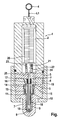
- the illustrated fuel injector has a built-up injector body 1, with two high-pressure chambers 2 and 3.
- the first high-pressure chamber 2 is continuously connected to a high-pressure source 4 for fuel via a bore passing through the injector body 1, this high-pressure source typically being designed as a so-called common rail.
- the second high-pressure chamber 3 communicates with the first high-pressure chamber 2 via a bore 7 passing through the intermediate bodies 5 and 6, so that pressure equality exists in the two chambers 2 and 3.
- the high-pressure chamber 3 is connected via the interior of a nozzle body 7 with the input side of injection nozzles 8, the output side open into a combustion chamber, not shown, of an engine or the like.
- the injection nozzles 8 are controlled by means of a nozzle needle 9, which is guided displaceably in the nozzle body 7 and with its in the drawing lower end with a within the Nozzle body 7 arranged, the inlet openings of the injectors 8 enclosing seat 10 cooperates.
- the outer circumference of the nozzle needle 9 and the inner circumference of the nozzle body 7 are shaped such that on the one hand a relatively play-free axial guidance of the nozzle needle 9 is ensured in the nozzle body 7 and on the other hand communicate the input sides of the injectors 8 with the second high-pressure chamber 3, when the nozzle needle 9 from the Seat 10 takes off open position.
- an annular disc 11 is formed, the outer periphery of the inner periphery of the leading from the high-pressure chamber 3 to the injectors 8 bore in the injector body 1 is closely adjacent, such that a ring gap choke 12 is formed.
- the purpose of the annular gap choke 12 will be explained below.
- a piston 13 is arranged with respect to the cross section of the nozzle needle 9 enlarged cross-section.
- a sealing sleeve 14 is slidably guided, which is clamped by a concentric to the piston 13 helical compression spring which is clamped between an annular step at the lower end of the high-pressure chamber 3 and the facing end face of the sealing sleeve 14, sealingly against the facing end face of the intermediate body. 6 is tense.
- the top edge of the sealing sleeve 14 in the drawing is tapered wedge-shaped, so that the sealing sleeve is sealingly seated on the intermediate body 6 at an annular contact zone.
- the sealing sleeve 14 separates above the piston 13 a servo chamber 15, which continues in a coaxial to the nozzle needle 9 hole in the intermediate body 6, from the high-pressure chamber 3.
- the servo chamber 15 is connected via an intermediate body 6 passing through throttle channel 16 with an annular groove 17 on the intermediate body 5 facing end face of the intermediate body 6 connected.
- the diameter of this annular groove 17 is dimensioned so that the annular groove without throttle communicates with the high-pressure chambers 2 and 3 connecting the bore, which passes through the intermediate body 5 and 6.
- the nozzle needle 9 is formed as a hollow needle with an open at the lower end of the nozzle needle 9 axial channel, the upper end opens into the servo chamber 15.
- a valve needle 18 is guided axially displaceable, the lower end cooperates with a seat at the lower end of the aforementioned axial channel in the nozzle needle 9 and controls the axial channel.
- In the illustrated closed position of the valve needle 8 of the axial channel is shut off in the nozzle needle 9.
- the valve needle 8 lifts from its seat at the lower end of the nozzle needle 9, the servo space 15 is connected to the input side of the injectors 8.
- the valve needle 18 is constantly clamped by a helical compression spring 19, which is clamped between an annular flange on the valve needle 18 and the lower end face of the intermediate body 5, in the seated on the seat 10 closed position.
- a piezoelectric actuator 20 is provided, which is hydraulically coupled to the valve needle 18 in a manner shown below.
- the actuator 20 is housed in the high pressure chamber 2 and formed in a basically known manner so that it elongates in the vertical direction when it is electrically charged, that is connected to an electrical voltage source (not shown). As soon as the actuator 20 is electrically discharged, it shortens in the vertical direction.
- a plungertellr master piston 21 is arranged on the outer circumference of a sealing sleeve 22 is slidably guided, which is tensioned by a concentric to the master piston 21 helical compression spring 23 against the upper end side of the intermediate body 5, wherein the intermediate body facing end edge of the sealing sleeve 22 has a wedge-shaped profile, so that the sealing sleeve 22 is seated with a ring-shaped sealing edge on the intermediate body 5.
- the sealing sleeve 22 downwardly exciting helical compression spring 23 simultaneously urges the actuator 20 upwards, such that its upper front end is constantly seated on an upper bottom of the injector body 1 and the ceramic of the piezoelectric actuator 20 is subjected to pressure only.
- the sealing sleeve 22 separates from the high-pressure chamber 2 from a transmitter chamber 24, which communicates with a slave chamber 25, which remains free in an upper plunger-like end of the valve needle 18 slidably receiving axial bore in the intermediate body 5 above the valve needle 18.
- the transmitter chamber increases, so that hydraulic fluid from the slave chamber 25 flows into the transmitter chamber 24 and the valve needle 18 can perform an upward stroke.
- the servo chamber 15 is shut off in the direction of the input side of the injection nozzles 8.
- the servo chamber 15, which communicates via the throttle bore 16 and the annular groove 17 with the high-pressure chamber 2 is charged to the high system pressure of the high-pressure chamber 2.
- the nozzle needle 9 is held in its closed position.
- valve needle 18 moves away from its seat at the lower end of the axial bore in the nozzle needle 9, and the servo chamber 15 is in communication with the input side of the injectors 8.
- the inlet side of the nozzles 8 has the same pressure as that on the nozzle needle 9 in the closed position the output side of the nozzles 8 arranged combustion chamber. Since the combustion chamber pressure is considerably lower than the pressure in the high-pressure chambers 2 and 3, the pressure in the servo chamber 15 drops correspondingly, whereby the throttle channel 16 prevents an inflow of high-pressure fluid which compensates for the pressure drop from occurring due to inflowing fluid from the high-pressure chamber 2.
- the high pressure in the High pressure chamber 3 is present and acts on the annular step between the nozzle needle 9 and servo piston 13 and on the partial cross section of the nozzle needle 9 outside the seat 10, that the nozzle needle 9 lifts off from the seat 10. This starts the injection phase, that is from the high-pressure chamber 3 flows under high pressure fluid to the input side of the injectors 8 and thus into the combustion chamber.
- a particular advantage of the invention is the fact that the nozzle needle 9 exactly follows the movement of the valve needle 18.
- valve needle 18 assume a position between its end positions in the course of a movement stroke. If the nozzle needle 9 in this case has a position in which the nozzle needle 9 passing axial channel is shut off, a high pressure will build up in the servo chamber 15, with the result that the nozzle needle 9 moves relative to the valve needle 18 slightly downward and the aforementioned axial channel is opened. Thus, the pressure in the servo chamber 15 drops below the pressure in the high pressure chambers 2 and 3, because at the input side of the injectors 8 due to unavoidable throttle losses in the flow path from the high pressure chamber 2 to the injectors 8, a lower pressure than in the high pressure chambers 2 and 3 is present.
- the stroke of the valve needle 18 caused by the actuator 20 is thus executed in a reproducible manner by the nozzle needle 9.
- the actuator 20 must However, only apply the necessary forces for the movements of the valve needle 19. Since the valve needle 18 in the slave chamber 25 and the master piston in the encoder chamber 24 are displaceable with different cross-sections, a corresponding Hubüber acid is effected, that is, the stroke of the valve needle 18 is greater by a predetermined by the quotient of the effective Verdrängerquerroughe factor than the stroke of the actuator 20th or the master piston 21. In this case, a corresponding translation of the actuating speeds, that is, the valve needle 18 moves together with the nozzle needle 9 significantly faster than the master piston 21st
- the construction shown in the drawing of the injector body 1 is shown only schematically.
- the nozzle body 7 can be held on a lower part body of the injector body 1, wherein the lower part body can be connected with the interposition of the intermediate body 5 and 6 with an upper body part of the injector body 1 by means of a sleeve-shaped nut.
Description
Die Erfindung bezieht sich auf einen Kraftstoffinjektor mit einem in dessen Injektorkörper angeordneten Hochdruckraum, welcher im Betrieb ständig mit einer Hochdruckquelle für Kraftstoff kommuniziert und über Düsen, die mittels einer servogesteuerten Düsennadel oder dergleichen gesteuert werden, zur Einspritzung von Kraftstoff mit einem Brennraum verbindbar ist, und mit einem Aktor, der zur Betätigung der Düsennadel den Druck in einem Servoarbeitsraum eines mit der Düsennadel zwangsgekoppelten Servokolbens steuert.The invention relates to a fuel injector with a arranged in the injector body high-pressure chamber which communicates constantly in operation with a high pressure fuel source and via nozzles which are controlled by a servo-controlled nozzle needle or the like, for injecting fuel with a combustion chamber is connected, and with an actuator which controls the actuation of the nozzle needle, the pressure in a servo workspace of a servo piston forcibly coupled to the nozzle needle.
Kraftstoffinjektoren werden serienmäßig in den Verbrennungsmotoren von Kraftfahrzeugen eingesetzt.Fuel injectors are used as standard in the internal combustion engines of motor vehicles.
Dies gilt insbesondere für Kraftstoffinjektoren der eingangs angegebenen Art mit servogesteuerter Düsennadel. Hier ist vorteilhaft, dass die Leistungsfähigkeit des Aktors vergleichsweise begrenzt sein darf, weil der Aktor lediglich eine zur Drucksteuerung im Servoarbeitsraum dienende Ventilanordnung betätigen muss.This applies in particular to fuel injectors of the type specified above with servo-controlled nozzle needle. Here it is advantageous that the performance of the actuator may be relatively limited, because the actuator only has to actuate a serving for pressure control in the servo workspace valve assembly.
Darüber hinaus werden auch Kraftstoffinjektoren mit direkt vom Aktor betätigter Düsennadel entwickelt, vergleiche bspw. die nicht vorveröffentlichte ältere Patentanmeldung (Unsere Akte: R 322715). Hier ist vorteilhaft, dass die Düsennadel den Aktorhüben praktisch verzögerungsfrei folgt. Um die Aktorkräfte bei direkter Betätigung der Düsennadel gering zu halten, ist einerseits vorgesehen, zwischen dem Hochdruckraum und der Eingangsseite der Düsen eine bei geöffneter Düsennadel wirksame Drossel vorzusehen, so dass zwischen dem Hochdruckraum und der Eingangsseite der Düsen in der Einspritzphase eine Druckdifferenz auftritt, die die Schließbewegung der Düsennadel am Ende der Einspritzphase unterstützt. Andererseits wird nur ein Teilquerschnitt an der Düsennadel in Schließrichtung beaufschlagt, während ein anderer Teilquerschnitt ständig vom Niederdruck eines Kraftstofftanks oder eines sonstigen Niederdrucksystems beaufschlagt wird. Damit können die notwendigen Öffnungskräfte für die Düsennadel vergleichsweise gering gehalten werden.In addition, fuel injectors are also developed with directly operated by the actuator nozzle needle, see, for example, the not previously published earlier patent application (Our file: R 322715). Here it is advantageous that the nozzle needle follows the Aktorhüben practically delay. In order to keep the Aktorkräfte low on direct actuation of the nozzle needle, on the one hand provided between the high-pressure chamber and the input side of the nozzle an effective throttle valve open, so that between the high-pressure chamber and the input side of the nozzle in the injection phase, a pressure difference occurs Supports the closing movement of the nozzle needle at the end of the injection phase. On the other hand, only a partial cross-section of the nozzle needle in the closing direction applied while another partial cross section is constantly acted upon by the low pressure of a fuel tank or other low pressure system. Thus, the necessary opening forces for the nozzle needle can be kept relatively low.
Grundsätzlich ist bei einem Kraftstoffinjektor das Problem gegeben, einerseits die Öffnungs- und Schließbewegungen der Düsennadel mit geringstmöglicher Verzögerung gegenüber den Aktorhüben durchzuführen, andererseits soll der Leistungsbedarf des Aktors gering gehalten werden. Deshalb ist es Aufgabe der Erfindung, bei einem Aktor mit servogesteuerter Düsennadel entsprechend der eingangs angegebenen Art eine besonders schnelle Reaktion der Düsennadel auf Aktorhübe zu gewährleisten.Basically, the problem is given in a fuel injector, on the one hand perform the opening and closing movements of the nozzle needle with the least possible delay against Aktorhüben, on the other hand, the power requirement of the actuator should be kept low. It is therefore an object of the invention to provide an actuator with servo-controlled nozzle needle according to the type specified a particularly rapid response of the nozzle needle to Aktorhübe.
Diese Aufgabe wird erfindungsgemäß dadurch gelöst, dass ein Teilquerschnitt des Servokolbens vom Druck im Hochdruckraum entgegen dem Druck im Servoarbeitsraum beaufschlagt und der Aktor mit einem Ventilkörper zwangsgekoppelt ist, der eine von den Betriebsstellungen der Düsennadel unabhängige Verbindung zwischen der Eingangsseite der Düsen und dem ständig gedrosselt mit dem Hochdruckraum kommunizierenden Servoarbeitsraum steuert.This object is achieved in that a partial cross section of the servo piston acted upon by the pressure in the high pressure chamber against the pressure in the servo workspace and the actuator is positively coupled to a valve body, which is independent of the operating positions of the nozzle needle connection between the input side of the nozzle and the constantly throttled with controls the servo workspace communicating with the high pressure space.
Die Erfindung beruht auf dem allgemeinen Gedanken, den Servoarbeitsraum hydraulisch derart anzuordnen, dass der Druck im Servoarbeitsraum einerseits auf den Druck im Hochdruckraum angehoben und andererseits auf den vergleichsweise vernachlässigbar geringen Druck im Brennraum, dass heißt auf der Ausgangsseite der Düsen, abgesenkt werden kann. Indem die Verbindung des Servoarbeitsraums zur Eingangsseite der Düsen mittels des aktorseitig betätigten Ventilkörpers gesperrt wird, wird der Servoarbeitsraum auf den Hochdruck des Hochdruckraums gebracht, mit der Folge, dass der Servokolben die Düsennadel in deren Schließlage stellt. Indem der Aktor den vorgenannten Ventilkörper in seine Offenlage bringt, wird die Verbindung zwischen Servoarbeitsraum und Eingangsseite der Düsen geöffnet, mit der Folge, dass der Druck im Servoarbeitsraum unter den Druck im Hochdruckraum abgesenkt wird und die Düsennadel von dem auf einen Teilquerschnitt des Servokolbens wirkenden Hochdruck geöffnet wird.The invention is based on the general idea of hydraulically arranging the servo work space such that the pressure in the servo work room can be raised to the pressure in the high-pressure space and lowered to the comparatively negligible pressure in the combustion space, that is to say on the outlet side of the nozzles. By blocking the connection of the servo working space to the inlet side of the nozzles by means of the actuator-actuated valve body, the servo working space is brought to the high pressure of the high-pressure chamber, with the result that the servo piston places the nozzle needle in its closed position. By the actuator brings the aforementioned valve body in its open position, the connection between the servo workspace and the inlet side of the nozzle is opened, with the result that the pressure in the servo work chamber is lowered below the pressure in the high-pressure chamber and the nozzle needle is opened by the high pressure acting on a partial cross-section of the servo piston.
Die Erfindung beruht auf der Erkenntnis, dass der vergleichsweise geringe Druck im Brennraum anstelle des im zum Beispiel
Ein besonderer Vorzug der Erfindung ist darin zu sehen, dass keinerlei Leitung zu einem weit entfernt angeordneten Niederdruckbereich, wie z. Bsp. Kraftstofftank, erforderlich wird. Der Kraftstoffinjektor muss also lediglich mit einer Hochdruckquelle für Kraftstoff, in der Regel ein Common Rail, verbunden sein.A particular advantage of the invention is the fact that no line to a far away low pressure area, such. Eg fuel tank, required. The fuel injector therefore only has to be connected to a high-pressure source for fuel, generally a common rail.
Gemäß einer konstruktiv vorteilhaften Ausführungsform der Erfindung können die Düsennadel als Hohlnadel mit einem den Servoarbeitsraum mit der Eingangsseite der Düsen verbindenden Axialkanal und der vom Aktor gesteuerte Ventilkörper als den Axialkanal steuernde Ventilnadel ausgebildet sein.According to a structurally advantageous embodiment of the invention, the nozzle needle can be configured as a hollow needle with an axial passage connecting the servo work space to the input side of the nozzles and the valve body controlled by the actuator as a valve needle controlling the axial passage.
Hierbei kann insbesondere vorgesehen sein, dass die Ventilnadel im Axialkanal verschiebbar geführt ist und mit einem am düsenseitigen Ende des Axialkanals angeordneten Sitz zusammenwirkt.In this case, it can be provided, in particular, that the valve needle is displaceably guided in the axial channel and cooperates with a seat arranged at the nozzle-side end of the axial channel.
Zur Optimierung des Schließverhaltens der Düsennadel kann zwischen Hochdruckraum und Eingangsseite der Düsen eine bei geöffneter Düsennadel wirksame Drossel angeordnet sein.To optimize the closing behavior of the nozzle needle can be arranged between the high-pressure chamber and the inlet side of the nozzle effective when the nozzle needle throttle.
In konstruktiv zweckmäßiger Ausgestaltung ist diese Drossel als Spaltdrossel zwischen dem Außenumfang der Düsennadel bzw. eines daran angeordneten Tellers oder dergleichen und dem Innenumfang eines an den Hochdruckraum des Injektorkörpers anschließenden Düsenkörpers ausgebildet, über dessen Innenraum der Hochdruckraum mit der Eingangsseite der Düsen kommuniziert.In a structurally expedient embodiment, this throttle is designed as a gap throttle between the outer circumference of the nozzle needle or a plate or the like arranged thereon and the inner circumference of a subsequent to the high-pressure chamber of the injector nozzle body, communicates through the interior of the high-pressure chamber with the input side of the nozzle.
Schließlich ist zwischen Hochdruckraum und Servoarbeitsraum vorzugsweise eine Drossel vorgesehen, mit der die Geschwindigkeit der Druckanhebung im Servoarbeitsraum bei Sperrung der Verbindung des Servoarbeitsraums zur Eingangsseite der Düsen bestimmt wird.Finally, a throttle is preferably provided between the high-pressure chamber and the servo working chamber, with which the speed of the pressure increase in the servo work space is determined when the connection of the servo work chamber to the input side of the nozzles is blocked.
Im Übrigen wird hinsichtlich bevorzugter Merkmale der Erfindung auf die Ansprüche und die nachfolgende Erläuterung der Zeichnung verwiesen, anhand der eine besonders bevorzugte Ausführungsform näher erläutert wird.Moreover, with regard to preferred features of the invention, reference is made to the claims and the following explanation of the drawing, with reference to a particularly preferred embodiment will be explained in more detail.
Schutz wird nicht nur für angegebene oder dargestellte Merkmalskombinationen sondern auch für prinzipiell beliebige Kombinationen der angegebenen oder dargestellten Einzelmerkmale beansprucht.Protection is claimed not only for specified or illustrated feature combinations but also for any combinations of the specified or illustrated individual features.
In der Zeichnung zeigt die einzige Fig. einen schematisierten Axialschnitt eines erfindungsgemäßen Kraftstoffinjektors.In the drawing, the only Fig. Shows a schematic axial section of a fuel injector according to the invention.
Der dargestellte Kraftstoffinjektor besitzt einen gebauten Injektorkörper 1, mit zwei Hochdruckräumen 2 und 3. Der erste Hockdruckraum 2 ist über eine den Injektorkörper 1 durchsetzende Bohrung ständig mit einer Hochdruckquelle 4 für Kraftstoff verbunden, wobei diese Hochdruckquelle typischerweise als so genanntes Common Rail ausgebildet ist. Der zweite Hochdruckraum 3 kommuniziert mit dem ersten Hochdruckraum 2 über eine die Zwischenkörper 5 und 6 durchsetzende Bohrung 7, so dass in den beiden Räumen 2 und 3 Druckgleichheit besteht.The illustrated fuel injector has a built-up injector body 1, with two high-
Der Hochdruckraum 3 ist über den Innenraum eines Düsenkörpers 7 mit der Eingangsseite von Einspritzdüsen 8 verbunden, die ausgangsseitig in einen nicht dargestellten Brennraum eines Motors oder dergleichen münden. Die Einspritzdüsen 8 werden mittels einer Düsennadel 9 gesteuert, die im Düsenkörper 7 verschiebbar geführt ist und mit ihrem in der Zeichnung unterem Ende mit einem innerhalb des Düsenkörpers 7 angeordneten, die Eingangsöffnungen der Einspritzdüsen 8 umschließenden Sitz 10 zusammenwirkt. Dabei sind der Außenumfang der Düsennadel 9 und der Innenumfang des Düsenkörpers 7 derartig geformt, dass einerseits eine relativ spielfreie Axialführung der Düsennadel 9 im Düsenkörper 7 gewährleistet ist und andererseits die Eingangsseiten der Einspritzdüsen 8 mit dem zweiten Hochdruckraum 3 kommunizieren, wenn die Düsennadel 9 ihre vom Sitz 10 abgehobene Offenstellung einnimmt. An der Düsennadel 9 ist eine Ringscheibe 11 angeformt, deren Außenumfang dem Innenumfang der vom Hochdruckraum 3 zu den Einspritzdüsen 8 führenden Bohrung im Injektorkörper 1 eng benachbart ist, derart, dass eine Ringsspaltdrossel 12 gebildet wird. Der Zweck der Ringspaltdrossel 12 wird weiter unten erläutert.The high-
Am in der Zeichnung oberen Ende der Düsennadel 9 ist ein Kolben 13 mit gegenüber dem Querschnitt der Düsennadel 9 vergrößertem Querschnitt angeordnet. Auf dem Außenumfang des Kolbens 13 ist eine Dichthülse 14 verschiebbar geführt, die von einer zum Kolben 13 konzentrischen Schraubendruckfeder, die zwischen einer Ringstufe am unteren Stirnende des Hochdruckraums 3 und der zugewandten Stirnseite der Dichthülse 14 eingespannt ist, dichtend gegen die zugewandte Stirnseite des Zwischenkörpers 6 gespannt wird. Dabei ist der in der Zeichnung obere Stirnrand der Dichthülse 14 keilförmig zugespitzt, so dass die Dichthülse auf dem Zwischenkörper 6 an einer ringlinienförmigen Berührungszone dichtend aufsitzt. Die Dichthülse 14 trennt oberhalb des Kolbens 13 einen Servoraum 15, der sich in eine zur Düsennadel 9 gleichachsige Bohrung im Zwischenkörper 6 fortsetzt, vom Hochdruckraum 3. Der Servoraum 15 ist über einen den Zwischenkörper 6 durchsetzenden Drosselkanal 16 mit einer Ringnut 17 auf der dem Zwischenkörper 5 zugewandten Stirnseite des Zwischenkörpers 6 verbunden. Der Durchmesser dieser Ringnut 17 ist so bemessen, dass die Ringnut drosselfrei mit der die Hochdruckräume 2 und 3 verbindenden Bohrung kommuniziert, die die Zwischenkörper 5 und 6 durchsetzt.At the top of the
Die Düsennadel 9 ist als Hohlnadel mit einem am unteren Ende der Düsennadel 9 offenen Axialkanal ausgebildet, dessen oberes Ende in den Servoraum 15 mündet. Innerhalb des Axialkanals ist eine Ventilnadel 18 axial verschiebbar geführt, deren unteres Ende mit einem Sitz am unteren Ende des vorgenannten Axialkanals in der Düsennadel 9 zusammenwirkt und den Axialkanal steuert. In der zeichnerisch dargestellten Schließlage der Ventilnadel 8 ist der Axialkanal in der Düsennadel 9 abgesperrt. Wenn die Ventilnadel 8 von ihrem Sitz am unteren Ende der Düsennadel 9 abhebt, wird der Servoraum 15 mit der Eingangsseite der Einspritzdüsen 8 verbunden. Die Ventilnadel 18 wird von einer Schraubendruckfeder 19, die zwischen einem Ringflansch an der Ventilnadel 18 und der unteren Stirnseite des Zwischenkörpers 5 eingespannt ist, ständig in die auf dem Sitz 10 aufsitzende Schließlage gespannt.The
Zur Betätigung der Ventilnadel 18 ist ein piezoelektrischer Aktor 20 vorgesehen, der mit der Ventilnadel 18 in weiter unten dargestellter Weise hydraulisch gekoppelt ist. Der Aktor 20 ist im Hochdruckraum 2 untergebracht und in grundsätzlich bekannter Weise so ausgebildet, dass er in Vertikalrichtung elongiert, wenn er elektrisch aufgeladen, das heißt mit einer elektrischen Spannungsquelle (nicht dargestellt) verbunden wird. Sobald der Aktor 20 elektrisch entladen wird, verkürzt er sich in Vertikalrichtung. Am in der Zeichnung unteren Ende des Aktors 20 ist ein plungerartiger Geberkolben 21 angeordnet, auf dessen Außenumfang eine Dichthülse 22 verschiebbar geführt ist, die von einer zum Geberkolben 21 konzentrischen Schraubendruckfeder 23 gegen die obere Stirnseite des Zwischenkörpers 5 gespannt wird, wobei der dem Zwischenkörper 5 zugewandte Stirnrand der Dichthülse 22 ein keilförmiges Profil besitzt, so dass die Dichthülse 22 mit einer ringlinienförmigen Dichtkante auf dem Zwischenkörper 5 aufsitzt. Die die Dichthülse 22 nach abwärts spannende Schraubendruckfeder 23 drängt gleichzeitig den Aktor 20 nach aufwärts, derart, dass dessen oberes Stirnende ständig auf einem oberen Boden des Injektorkörpers 1 aufsitzt und die Keramik des piezoelektrischen Aktors 20 nur auf Druck beansprucht wird.For actuating the
Die Dichthülse 22 trennt vom Hochdruckraum 2 einen Geberraum 24 ab, der mit einem Nehmerraum 25 kommuniziert, welcher in einer das obere plungerartige Ende der Ventilnadel 18 verschiebbar aufnehmenden Axialbohrung im Zwischenkörper 5 oberhalb der Ventilnadel 18 frei bleibt. Wenn also der Geberkolben 21 vom Aktor 20 nach abwärts bewegt wird und dabei den Geberraum 24 verkleinert, wird Hydraulikmedium aus dem Geberraum 24 in den Nehmerraum 25 ausgeschoben, so dass der vom oberen plungerartigen Ende der Ventilnadel 18 gebildete Nehmerkolben in Abwärtsrichtung gedrängt wird.The
Wenn andererseits der Geberkolben 21 eine Aufwärtsbewegung ausführt, vergrößert sich der Geberraum, so dass Hydraulikmedium aus dem Nehmerraum 25 in den Geberraum 24 überströmt und die Ventilnadel 18 einen Aufwärtshub ausführen kann.On the other hand, when the
Der dargestellte Kraftstoffinjektor funktioniert wie folgt:
- Zunächst sei davon ausgegangen, dass die
Düsennadel 9 und dieVentilnadel 18 die in der Zeichnung dargestellten unteren Endlagen einnehmen, das heißt dieDüsennadel 9 sitzt auf demSitz 10, und dieVentilnadel 18 sitzt auf dem Sitz am unteren Ende der Axialbohrung in derDüsennadel 9.
- First, assume that the
nozzle needle 9 and thevalve needle 18 take the lower end positions shown in the drawing, that is, thenozzle needle 9 is seated on theseat 10, and thevalve needle 18 is seated on the seat at the lower end of the axial bore in the nozzle needle. 9 ,
Damit ist der Servoraum 15 in Richtung zur Eingangsseite der Einspritzdüsen 8 abgesperrt. Dies bedeutet, dass der Servoraum 15, der über die Drosselbohrung 16 und die Ringnut 17 mit dem Hochdruckraum 2 kommuniziert, auf den hohen Systemdruck des Hochdruckraums 2 aufgeladen wird bzw. ist. Damit wird die Düsennadel 9 in ihrer Schließlage gehalten. Wenn nun der Aktor 20, der in der Zeichnung seinen elektrisch geladenen elongierten Zustand einnimmt, elektrisch entladen wird und sich dementsprechend verkürzt, wird der Geberkolben 21 angehoben, so dass sich der Geberraum 24 entsprechend vergrößert. Dies hat zur Folge, dass aus dem Nehmerraum 25 Fluid in den Geberraum 24 überströmt und die Ventilnadel 18 einen entsprechenden Aufwärtshub ausführt. Damit entfernt sich die Ventilnadel 18 von ihrem Sitz am unteren Ende der Axialbohrung in der Düsennadel 9, und der Servoraum 15 erhält Verbindung mit der Eingangsseite der Einspritzdüsen 8. Die Eingangsseite der Düsen 8 hat bei in Schließlage befindlicher Düsennadel 9 den gleichen Druck wie der auf der Ausgangsseite der Düsen 8 angeordnete Brennraum. Da der Brennraumdruck erheblich niedriger ist als der Druck in den Hochdruckräumen 2 und 3, sinkt der Druck im Servoraum 15 entsprechend ab, wobei der Drosselkanal 16 verhindert, dass durch nachströmendes Fluid aus dem Hochdruckraum 2 ein die Druckabsenkung kompensierender Zufluss von Hochdruckfluid auftreten kann. Sobald der Druck im Servoraum 15 hinreichend abgesunken ist, bewirkt der Hochdruck, der im Hochdruckraum 3 ansteht und auf die Ringstufe zwischen Düsennadel 9 und Servokolben 13 sowie auf den Teilquerschnitt der Düsennadel 9 außerhalb des Sitzes 10 wirkt, dass die Düsennadel 9 vom Sitz 10 abhebt. Damit beginnt die Einspritzphase, das heißt aus dem Hochdruckraum 3 strömt unter Hochdruck stehendes Fluid zur Eingangsseite der Einspritzdüsen 8 und damit in den Brennraum.Thus, the
Ein besonderer Vorzug der Erfindung ist darin zu sehen, dass die Düsennadel 9 genau der Bewegung der Ventilnadel 18 folgt.A particular advantage of the invention is the fact that the
Beispielsweise möge die Ventilnadel 18 im Verlauf eines Bewegungshubs eine Lage zwischen ihren Endlagen einnehmen. Wenn die Düsennadel 9 in diesem Falle eine Lage hat, bei der der die Düsennadel 9 durchsetzende Axialkanal abgesperrt wird, wird sich im Servoraum 15 ein hoher Druck aufbauen, mit der Folge, dass die Düsennadel 9 sich relativ zur Ventilnadel 18 etwas nach abwärts bewegt und der vorgenannte Axialkanal geöffnet wird. Damit sinkt der Druck im Servoraum 15 unter den Druck in den Hochdruckräumen 2 und 3 ab, weil an der Eingangsseite der Einspritzdüsen 8 aufgrund von unvermeidlichen Drosselverlusten im Strömungsweg vom Hochdruckraum 2 zu den Einspritzdüsen 8 ein geringerer Druck als in den Hochdruckräumen 2 und 3 vorliegt. Dieser Effekt wird noch zusätzlich dadurch unterstützt, dass in diesem Strömungsweg die Ringsspaltdrossel 12 vorgesehen ist. Damit stellt sich im Servoraum 15 ein vergleichsweise geringer Druck ein, derart, dass der im Hochdruckraum 3 vorliegende Druck, welcher auf die Ringstufe zwischen dem Servokolben 13 und der Düsennadel 9 wirkt, die Düsennadel 9 relativ zur Ventilnadel 18 wieder nach aufwärts schieben kann, so dass der Axialkanal in der Düsennadel 9 zunehmend gedrosselt wird. Im Ergebnis wird sich damit eine Relativstellung der Düsennadel 9 relativ zur Ventilnadel 18 einstellen, derart, dass die Düsennadel 9 relativ zur Ventilnadel 18 eine gleich bleibende Lage einnimmt, dass heißt relativ zur Ventilnadel 18 praktisch in Ruhe bleibt. Im Servoraum 15 stellt sich dabei immer genau ein solcher Druck ein, dass die Düsennadel 9 der Bewegung der Ventilnadel 18 praktisch verzögerungsfrei folgt.For example, let the
Die vom Aktor 20 bewirkte Hubbewegung der Ventilnadel 18 wird also in reproduzierbarer Weise auch von der Düsennadel 9 ausgeführt. Der Aktor 20 muss jedoch lediglich die für die Bewegungen der Ventilnadel 19 notwendigen Kräfte aufbringen. Da die Ventilnadel 18 im Nehmerraum 25 und der Geberkolben im Geberraum 24 mit unterschiedlichen Querschnitten verdrängerwirksam sind, wird eine entsprechende Hubübersetzung bewirkt, das heißt der Hub der Ventilnadel 18 ist um einen durch den Quotienten der wirksamen Verdrängerquerschnitte vorgegebenen Faktor größer als der Hub des Aktors 20 oder des Geberkolbens 21. Hierbei erfolgt auch eine entsprechende Übersetzung der Stellgeschwindigkeiten, das heißt die Ventilnadel 18 bewegt sich zusammen mit der Düsennadel 9 deutlich schneller als der Geberkolben 21.The stroke of the
Der zeichnerisch dargestellte Aufbau des Injektorkörpers 1 ist lediglich schematisiert wiedergegeben. Insbesondere wird in der Zeichnung erkennbar, dass der Düsenkörper 7 an einem unteren Teilkörper des Injektorkörpers 1 gehaltert sein kann, wobei der untere Teilkörper unter Zwischenschaltung der Zwischenkörper 5 und 6 mit einem oberen Teilkörper des Injektorkörpers 1 mittels einer hülsenförmigen Überwurfmutter verbunden sein kann.The construction shown in the drawing of the injector body 1 is shown only schematically. In particular, it can be seen in the drawing that the
Claims (10)
- Fuel injector having a high-pressure chamber (2, 3) which is arranged in the injector body (1) of said fuel injector and which, during operation, permanently communicates with a high-pressure source (4) for fuel and which, for the injection of fuel, can be connected to a combustion chamber via nozzles (8) which are controlled by means of a servo-controlled nozzle needle (9) or the like, and having an actuator (20) which, for the actuation of the nozzle needle (9), controls the pressure in a servo working chamber (15) of a servo piston (13) which is positively coupled to the nozzle needle (9),
characterized
in that a partial cross section of the servo piston (13) is acted on by the pressure in the high-pressure chamber (2, 3) counter to the pressure in the servo working chamber (15), and the actuator (20) is positively coupled to a valve body (18) which controls a connection, which is independent of operating positions of the nozzle needle (9), between the inlet side of the nozzles (8) and the servo working chamber (15) which permanently communicates in throttled fashion with the high-pressure chamber (2, 3). - Fuel injector according to Claim 1,
characterized
in that the valve body is formed as a valve needle (18) which controls an axial duct extending through the servo piston (13) and through the nozzle needle (9) which adjoins said servo piston. - Fuel injector according to Claim 2,
characterized
in that the valve needle (18) is guided in a displaceable manner in the axial duct and interacts with a seat arranged on the nozzle-side end of the axial duct. - Fuel injector according to one of Claims 1 to 3,
characterized
in that a throttle (12) is arranged between the high-pressure chamber (2, 3) and the inlet side of the nozzles (8). - Fuel injector according to Claim 4,
characterized
in that the throttle (12) is formed between the outer circumference of an annular disc (11), which is arranged on the nozzle needle (9), and the inner circumference of an interior space, which adjoins the inlet side of the nozzles (8), of a nozzle body (7), close to an axial guide of the nozzle needle (9) in the nozzle body (7). - Fuel injector according to one of Claims 2 to 5,
characterized
in that the valve body or the valve needle (18) and the actuator (20) are hydraulically coupled in terms of drive. - Fuel injector according to Claim 6,
characterized
in that the actuator (20) is connected to a master piston (21), which acts as a displacement body in a coupling chamber (24, 25), and the valve needle (18) is connected to a plunger which is remote from the nozzle and which, as a slave piston, acts as a displacement body in the coupling chamber (24, 25). - Fuel injector according to Claim 6 or 7,
characterized
in that the coupling chamber (24, 25) has a master chamber (24) within a sealing sleeve (22), which sealing sleeve is displaceably guided on the plunger-like master piston (21) which is connected to one end of the actuator (20), and which sealing sleeve is braced sealingly against a base (5) in the injector body (1) by a spring arrangement (23) which is braced between the facing ends of the actuator (20) and sealing sleeve (22). - Fuel injector according to one of Claims 6 to 8,
characterized
in that the master piston (21) has a larger cross section than the slave piston (18). - Fuel injector according to Claim 9,
characterized
in that the plunger-like end, which is remote from the nozzle, of the valve needle (18) is provided as a slave piston.
Applications Claiming Priority (1)
| Application Number | Priority Date | Filing Date | Title |
|---|---|---|---|
| DE200910002621 DE102009002621A1 (en) | 2009-04-24 | 2009-04-24 | fuel injector |
Publications (2)
| Publication Number | Publication Date |
|---|---|
| EP2246553A1 EP2246553A1 (en) | 2010-11-03 |
| EP2246553B1 true EP2246553B1 (en) | 2013-04-10 |
Family
ID=42167501
Family Applications (1)
| Application Number | Title | Priority Date | Filing Date |
|---|---|---|---|
| EP20100154614 Not-in-force EP2246553B1 (en) | 2009-04-24 | 2010-02-25 | Fuel injector |
Country Status (2)
| Country | Link |
|---|---|
| EP (1) | EP2246553B1 (en) |
| DE (1) | DE102009002621A1 (en) |
Family Cites Families (3)
| Publication number | Priority date | Publication date | Assignee | Title |
|---|---|---|---|---|
| DE10348925A1 (en) * | 2003-10-18 | 2005-05-12 | Bosch Gmbh Robert | Fuel injector with multipart, directly controlled injection valve member |
| DE102006019736A1 (en) * | 2006-04-28 | 2007-10-31 | Robert Bosch Gmbh | Fuel injector for combustion chamber of internal combustion engine, has actuator arranged in low-pressure area and surrounded by fuel, and compensation unit e.g. housing part, formed in low-pressure area |
| DE102006035983A1 (en) * | 2006-08-02 | 2008-02-07 | Robert Bosch Gmbh | Fuel Injector for internal-combustion engine in motor vehicle, has stop formed between nozzle needles, where one of nozzle needles comes in attachment with other nozzle needle through stop during preset control stroke |
-
2009
- 2009-04-24 DE DE200910002621 patent/DE102009002621A1/en not_active Withdrawn
-
2010
- 2010-02-25 EP EP20100154614 patent/EP2246553B1/en not_active Not-in-force
Also Published As
| Publication number | Publication date |
|---|---|
| DE102009002621A1 (en) | 2010-10-28 |
| EP2246553A1 (en) | 2010-11-03 |
Similar Documents
| Publication | Publication Date | Title |
|---|---|---|
| EP1853813B1 (en) | Injection nozzle | |
| EP2386746B1 (en) | Fuel injector | |
| EP1144857B1 (en) | Dual-switching control valve with reinforcement of the hydraulic actuator | |
| WO2006069899A1 (en) | Fuel injector with direct control of the injection valve body | |
| EP1865192A2 (en) | Fuel injector with servo assistance | |
| DE102008002416A1 (en) | Fuel injector has injector housing or body, high-pressure chambers or storages, which are constantly connected with high-pressure source for fuel, and nozzle needle | |
| EP1682769B1 (en) | Fuel injector with a multipart, directly controlled injection valve element | |
| EP1925812B1 (en) | Fuel injector valve for combustion engines | |
| EP2103802A1 (en) | Injector | |
| EP2246553B1 (en) | Fuel injector | |
| EP1591655B1 (en) | Injection Nozzle | |
| EP1637727B1 (en) | Control valve for an injector | |
| EP1703118B1 (en) | Injector nozzle | |
| EP1825134B1 (en) | Fuel injection nozzle | |
| WO2006029937A1 (en) | Control valve for an injection nozzle of an internal combustion engine | |
| EP1908953B1 (en) | Fuel injection device | |
| EP1825137B1 (en) | Fuel injection nozzle | |
| EP2204570B1 (en) | Fuel injector | |
| EP2199590B1 (en) | Fuel injector | |
| DE102009002528A1 (en) | fuel injector | |
| EP1662131B1 (en) | Fuel injection nozzle | |
| EP1256708A2 (en) | Fuel injection device for an internal-combustion engine | |
| DE102014206210A1 (en) | fuel injector | |
| EP2905458A1 (en) | Nozzle assembly for a fuel injector and fuel injector | |
| DE102014211469A1 (en) | Nozzle assembly for a fuel injector and fuel injector |
Legal Events
| Date | Code | Title | Description |
|---|---|---|---|
| PUAI | Public reference made under article 153(3) epc to a published international application that has entered the european phase |
Free format text: ORIGINAL CODE: 0009012 |
|
| AK | Designated contracting states |
Kind code of ref document: A1 Designated state(s): AT BE BG CH CY CZ DE DK EE ES FI FR GB GR HR HU IE IS IT LI LT LU LV MC MK MT NL NO PL PT RO SE SI SK SM TR |
|
| AX | Request for extension of the european patent |
Extension state: AL BA RS |
|
| 17P | Request for examination filed |
Effective date: 20110503 |
|
| GRAP | Despatch of communication of intention to grant a patent |
Free format text: ORIGINAL CODE: EPIDOSNIGR1 |
|
| RIC1 | Information provided on ipc code assigned before grant |
Ipc: F02M 63/00 20060101ALI20121120BHEP Ipc: F02M 61/10 20060101ALI20121120BHEP Ipc: F02M 47/02 20060101AFI20121120BHEP |
|
| GRAS | Grant fee paid |
Free format text: ORIGINAL CODE: EPIDOSNIGR3 |
|
| GRAA | (expected) grant |
Free format text: ORIGINAL CODE: 0009210 |
|
| AK | Designated contracting states |
Kind code of ref document: B1 Designated state(s): AT BE BG CH CY CZ DE DK EE ES FI FR GB GR HR HU IE IS IT LI LT LU LV MC MK MT NL NO PL PT RO SE SI SK SM TR |
|
| REG | Reference to a national code |
Ref country code: GB Ref legal event code: FG4D Free format text: NOT ENGLISH |
|
| REG | Reference to a national code |
Ref country code: CH Ref legal event code: EP Ref country code: AT Ref legal event code: REF Ref document number: 606152 Country of ref document: AT Kind code of ref document: T Effective date: 20130415 |
|
| REG | Reference to a national code |
Ref country code: IE Ref legal event code: FG4D Free format text: LANGUAGE OF EP DOCUMENT: GERMAN |
|
| REG | Reference to a national code |
Ref country code: DE Ref legal event code: R096 Ref document number: 502010002904 Country of ref document: DE Effective date: 20130606 |
|
| PG25 | Lapsed in a contracting state [announced via postgrant information from national office to epo] |
Ref country code: SI Free format text: LAPSE BECAUSE OF FAILURE TO SUBMIT A TRANSLATION OF THE DESCRIPTION OR TO PAY THE FEE WITHIN THE PRESCRIBED TIME-LIMIT Effective date: 20130410 |
|
| REG | Reference to a national code |
Ref country code: NL Ref legal event code: VDEP Effective date: 20130410 Ref country code: LT Ref legal event code: MG4D |
|
| PG25 | Lapsed in a contracting state [announced via postgrant information from national office to epo] |
Ref country code: SE Free format text: LAPSE BECAUSE OF FAILURE TO SUBMIT A TRANSLATION OF THE DESCRIPTION OR TO PAY THE FEE WITHIN THE PRESCRIBED TIME-LIMIT Effective date: 20130410 Ref country code: NO Free format text: LAPSE BECAUSE OF FAILURE TO SUBMIT A TRANSLATION OF THE DESCRIPTION OR TO PAY THE FEE WITHIN THE PRESCRIBED TIME-LIMIT Effective date: 20130710 Ref country code: FI Free format text: LAPSE BECAUSE OF FAILURE TO SUBMIT A TRANSLATION OF THE DESCRIPTION OR TO PAY THE FEE WITHIN THE PRESCRIBED TIME-LIMIT Effective date: 20130410 Ref country code: NL Free format text: LAPSE BECAUSE OF FAILURE TO SUBMIT A TRANSLATION OF THE DESCRIPTION OR TO PAY THE FEE WITHIN THE PRESCRIBED TIME-LIMIT Effective date: 20130410 Ref country code: ES Free format text: LAPSE BECAUSE OF FAILURE TO SUBMIT A TRANSLATION OF THE DESCRIPTION OR TO PAY THE FEE WITHIN THE PRESCRIBED TIME-LIMIT Effective date: 20130721 Ref country code: PT Free format text: LAPSE BECAUSE OF FAILURE TO SUBMIT A TRANSLATION OF THE DESCRIPTION OR TO PAY THE FEE WITHIN THE PRESCRIBED TIME-LIMIT Effective date: 20130812 Ref country code: LT Free format text: LAPSE BECAUSE OF FAILURE TO SUBMIT A TRANSLATION OF THE DESCRIPTION OR TO PAY THE FEE WITHIN THE PRESCRIBED TIME-LIMIT Effective date: 20130410 Ref country code: IS Free format text: LAPSE BECAUSE OF FAILURE TO SUBMIT A TRANSLATION OF THE DESCRIPTION OR TO PAY THE FEE WITHIN THE PRESCRIBED TIME-LIMIT Effective date: 20130810 Ref country code: GR Free format text: LAPSE BECAUSE OF FAILURE TO SUBMIT A TRANSLATION OF THE DESCRIPTION OR TO PAY THE FEE WITHIN THE PRESCRIBED TIME-LIMIT Effective date: 20130711 |
|
| PG25 | Lapsed in a contracting state [announced via postgrant information from national office to epo] |
Ref country code: PL Free format text: LAPSE BECAUSE OF FAILURE TO SUBMIT A TRANSLATION OF THE DESCRIPTION OR TO PAY THE FEE WITHIN THE PRESCRIBED TIME-LIMIT Effective date: 20130410 Ref country code: BG Free format text: LAPSE BECAUSE OF FAILURE TO SUBMIT A TRANSLATION OF THE DESCRIPTION OR TO PAY THE FEE WITHIN THE PRESCRIBED TIME-LIMIT Effective date: 20130710 Ref country code: HR Free format text: LAPSE BECAUSE OF FAILURE TO SUBMIT A TRANSLATION OF THE DESCRIPTION OR TO PAY THE FEE WITHIN THE PRESCRIBED TIME-LIMIT Effective date: 20130410 Ref country code: LV Free format text: LAPSE BECAUSE OF FAILURE TO SUBMIT A TRANSLATION OF THE DESCRIPTION OR TO PAY THE FEE WITHIN THE PRESCRIBED TIME-LIMIT Effective date: 20130410 Ref country code: CY Free format text: LAPSE BECAUSE OF FAILURE TO SUBMIT A TRANSLATION OF THE DESCRIPTION OR TO PAY THE FEE WITHIN THE PRESCRIBED TIME-LIMIT Effective date: 20130410 |
|
| PG25 | Lapsed in a contracting state [announced via postgrant information from national office to epo] |
Ref country code: DK Free format text: LAPSE BECAUSE OF FAILURE TO SUBMIT A TRANSLATION OF THE DESCRIPTION OR TO PAY THE FEE WITHIN THE PRESCRIBED TIME-LIMIT Effective date: 20130410 Ref country code: CZ Free format text: LAPSE BECAUSE OF FAILURE TO SUBMIT A TRANSLATION OF THE DESCRIPTION OR TO PAY THE FEE WITHIN THE PRESCRIBED TIME-LIMIT Effective date: 20130410 Ref country code: EE Free format text: LAPSE BECAUSE OF FAILURE TO SUBMIT A TRANSLATION OF THE DESCRIPTION OR TO PAY THE FEE WITHIN THE PRESCRIBED TIME-LIMIT Effective date: 20130410 Ref country code: SK Free format text: LAPSE BECAUSE OF FAILURE TO SUBMIT A TRANSLATION OF THE DESCRIPTION OR TO PAY THE FEE WITHIN THE PRESCRIBED TIME-LIMIT Effective date: 20130410 |
|
| PLBE | No opposition filed within time limit |
Free format text: ORIGINAL CODE: 0009261 |
|
| STAA | Information on the status of an ep patent application or granted ep patent |
Free format text: STATUS: NO OPPOSITION FILED WITHIN TIME LIMIT |
|
| PG25 | Lapsed in a contracting state [announced via postgrant information from national office to epo] |
Ref country code: RO Free format text: LAPSE BECAUSE OF FAILURE TO SUBMIT A TRANSLATION OF THE DESCRIPTION OR TO PAY THE FEE WITHIN THE PRESCRIBED TIME-LIMIT Effective date: 20130410 Ref country code: IT Free format text: LAPSE BECAUSE OF FAILURE TO SUBMIT A TRANSLATION OF THE DESCRIPTION OR TO PAY THE FEE WITHIN THE PRESCRIBED TIME-LIMIT Effective date: 20130410 |
|
| 26N | No opposition filed |
Effective date: 20140113 |
|
| REG | Reference to a national code |
Ref country code: DE Ref legal event code: R097 Ref document number: 502010002904 Country of ref document: DE Effective date: 20140113 |
|
| BERE | Be: lapsed |
Owner name: ROBERT BOSCH G.M.B.H. Effective date: 20140228 |
|
| PG25 | Lapsed in a contracting state [announced via postgrant information from national office to epo] |
Ref country code: MC Free format text: LAPSE BECAUSE OF FAILURE TO SUBMIT A TRANSLATION OF THE DESCRIPTION OR TO PAY THE FEE WITHIN THE PRESCRIBED TIME-LIMIT Effective date: 20130410 Ref country code: LU Free format text: LAPSE BECAUSE OF FAILURE TO SUBMIT A TRANSLATION OF THE DESCRIPTION OR TO PAY THE FEE WITHIN THE PRESCRIBED TIME-LIMIT Effective date: 20140225 |
|
| REG | Reference to a national code |
Ref country code: CH Ref legal event code: PL |
|
| GBPC | Gb: european patent ceased through non-payment of renewal fee |
Effective date: 20140225 |
|
| PG25 | Lapsed in a contracting state [announced via postgrant information from national office to epo] |
Ref country code: LI Free format text: LAPSE BECAUSE OF NON-PAYMENT OF DUE FEES Effective date: 20140228 Ref country code: CH Free format text: LAPSE BECAUSE OF NON-PAYMENT OF DUE FEES Effective date: 20140228 |
|
| REG | Reference to a national code |
Ref country code: IE Ref legal event code: MM4A |
|
| PG25 | Lapsed in a contracting state [announced via postgrant information from national office to epo] |
Ref country code: GB Free format text: LAPSE BECAUSE OF NON-PAYMENT OF DUE FEES Effective date: 20140225 Ref country code: IE Free format text: LAPSE BECAUSE OF NON-PAYMENT OF DUE FEES Effective date: 20140225 Ref country code: BE Free format text: LAPSE BECAUSE OF NON-PAYMENT OF DUE FEES Effective date: 20140228 |
|
| REG | Reference to a national code |
Ref country code: FR Ref legal event code: PLFP Year of fee payment: 7 |
|
| PG25 | Lapsed in a contracting state [announced via postgrant information from national office to epo] |
Ref country code: MT Free format text: LAPSE BECAUSE OF FAILURE TO SUBMIT A TRANSLATION OF THE DESCRIPTION OR TO PAY THE FEE WITHIN THE PRESCRIBED TIME-LIMIT Effective date: 20130410 |
|
| REG | Reference to a national code |
Ref country code: AT Ref legal event code: MM01 Ref document number: 606152 Country of ref document: AT Kind code of ref document: T Effective date: 20150225 |
|
| PG25 | Lapsed in a contracting state [announced via postgrant information from national office to epo] |
Ref country code: SM Free format text: LAPSE BECAUSE OF FAILURE TO SUBMIT A TRANSLATION OF THE DESCRIPTION OR TO PAY THE FEE WITHIN THE PRESCRIBED TIME-LIMIT Effective date: 20130410 |
|
| PG25 | Lapsed in a contracting state [announced via postgrant information from national office to epo] |
Ref country code: AT Free format text: LAPSE BECAUSE OF NON-PAYMENT OF DUE FEES Effective date: 20150225 |
|
| PG25 | Lapsed in a contracting state [announced via postgrant information from national office to epo] |
Ref country code: HU Free format text: LAPSE BECAUSE OF FAILURE TO SUBMIT A TRANSLATION OF THE DESCRIPTION OR TO PAY THE FEE WITHIN THE PRESCRIBED TIME-LIMIT; INVALID AB INITIO Effective date: 20100225 Ref country code: TR Free format text: LAPSE BECAUSE OF FAILURE TO SUBMIT A TRANSLATION OF THE DESCRIPTION OR TO PAY THE FEE WITHIN THE PRESCRIBED TIME-LIMIT Effective date: 20130410 |
|
| REG | Reference to a national code |
Ref country code: FR Ref legal event code: PLFP Year of fee payment: 8 |
|
| REG | Reference to a national code |
Ref country code: FR Ref legal event code: PLFP Year of fee payment: 9 |
|
| PG25 | Lapsed in a contracting state [announced via postgrant information from national office to epo] |
Ref country code: MK Free format text: LAPSE BECAUSE OF FAILURE TO SUBMIT A TRANSLATION OF THE DESCRIPTION OR TO PAY THE FEE WITHIN THE PRESCRIBED TIME-LIMIT Effective date: 20130410 |
|
| PGFP | Annual fee paid to national office [announced via postgrant information from national office to epo] |
Ref country code: FR Payment date: 20190221 Year of fee payment: 10 |
|
| PGFP | Annual fee paid to national office [announced via postgrant information from national office to epo] |
Ref country code: DE Payment date: 20190423 Year of fee payment: 10 |
|
| REG | Reference to a national code |
Ref country code: DE Ref legal event code: R119 Ref document number: 502010002904 Country of ref document: DE |
|
| PG25 | Lapsed in a contracting state [announced via postgrant information from national office to epo] |
Ref country code: DE Free format text: LAPSE BECAUSE OF NON-PAYMENT OF DUE FEES Effective date: 20200901 Ref country code: FR Free format text: LAPSE BECAUSE OF NON-PAYMENT OF DUE FEES Effective date: 20200229 |