EP2246540A1 - Vehicle power generation system using exhaust gas - Google Patents
Vehicle power generation system using exhaust gas Download PDFInfo
- Publication number
- EP2246540A1 EP2246540A1 EP10275043A EP10275043A EP2246540A1 EP 2246540 A1 EP2246540 A1 EP 2246540A1 EP 10275043 A EP10275043 A EP 10275043A EP 10275043 A EP10275043 A EP 10275043A EP 2246540 A1 EP2246540 A1 EP 2246540A1
- Authority
- EP
- European Patent Office
- Prior art keywords
- casing
- exhaust gas
- inlet hole
- turbine
- wing
- Prior art date
- Legal status (The legal status is an assumption and is not a legal conclusion. Google has not performed a legal analysis and makes no representation as to the accuracy of the status listed.)
- Granted
Links
Images

Classifications
-
- F—MECHANICAL ENGINEERING; LIGHTING; HEATING; WEAPONS; BLASTING
- F01—MACHINES OR ENGINES IN GENERAL; ENGINE PLANTS IN GENERAL; STEAM ENGINES
- F01N—GAS-FLOW SILENCERS OR EXHAUST APPARATUS FOR MACHINES OR ENGINES IN GENERAL; GAS-FLOW SILENCERS OR EXHAUST APPARATUS FOR INTERNAL COMBUSTION ENGINES
- F01N5/00—Exhaust or silencing apparatus combined or associated with devices profiting from exhaust energy
- F01N5/04—Exhaust or silencing apparatus combined or associated with devices profiting from exhaust energy the devices using kinetic energy
-
- F—MECHANICAL ENGINEERING; LIGHTING; HEATING; WEAPONS; BLASTING
- F01—MACHINES OR ENGINES IN GENERAL; ENGINE PLANTS IN GENERAL; STEAM ENGINES
- F01D—NON-POSITIVE DISPLACEMENT MACHINES OR ENGINES, e.g. STEAM TURBINES
- F01D1/00—Non-positive-displacement machines or engines, e.g. steam turbines
- F01D1/02—Non-positive-displacement machines or engines, e.g. steam turbines with stationary working-fluid guiding means and bladed or like rotor, e.g. multi-bladed impulse steam turbines
- F01D1/026—Impact turbines with buckets, i.e. impulse turbines, e.g. Pelton turbines
-
- F—MECHANICAL ENGINEERING; LIGHTING; HEATING; WEAPONS; BLASTING
- F01—MACHINES OR ENGINES IN GENERAL; ENGINE PLANTS IN GENERAL; STEAM ENGINES
- F01N—GAS-FLOW SILENCERS OR EXHAUST APPARATUS FOR MACHINES OR ENGINES IN GENERAL; GAS-FLOW SILENCERS OR EXHAUST APPARATUS FOR INTERNAL COMBUSTION ENGINES
- F01N5/00—Exhaust or silencing apparatus combined or associated with devices profiting from exhaust energy
-
- F—MECHANICAL ENGINEERING; LIGHTING; HEATING; WEAPONS; BLASTING
- F02—COMBUSTION ENGINES; HOT-GAS OR COMBUSTION-PRODUCT ENGINE PLANTS
- F02M—SUPPLYING COMBUSTION ENGINES IN GENERAL WITH COMBUSTIBLE MIXTURES OR CONSTITUENTS THEREOF
- F02M21/00—Apparatus for supplying engines with non-liquid fuels, e.g. gaseous fuels stored in liquid form
- F02M21/02—Apparatus for supplying engines with non-liquid fuels, e.g. gaseous fuels stored in liquid form for gaseous fuels
- F02M21/0203—Apparatus for supplying engines with non-liquid fuels, e.g. gaseous fuels stored in liquid form for gaseous fuels characterised by the type of gaseous fuel
- F02M21/0206—Non-hydrocarbon fuels, e.g. hydrogen, ammonia or carbon monoxide
-
- F—MECHANICAL ENGINEERING; LIGHTING; HEATING; WEAPONS; BLASTING
- F02—COMBUSTION ENGINES; HOT-GAS OR COMBUSTION-PRODUCT ENGINE PLANTS
- F02M—SUPPLYING COMBUSTION ENGINES IN GENERAL WITH COMBUSTIBLE MIXTURES OR CONSTITUENTS THEREOF
- F02M21/00—Apparatus for supplying engines with non-liquid fuels, e.g. gaseous fuels stored in liquid form
- F02M21/02—Apparatus for supplying engines with non-liquid fuels, e.g. gaseous fuels stored in liquid form for gaseous fuels
- F02M21/0218—Details on the gaseous fuel supply system, e.g. tanks, valves, pipes, pumps, rails, injectors or mixers
- F02M21/0227—Means to treat or clean gaseous fuels or fuel systems, e.g. removal of tar, cracking, reforming or enriching
-
- F—MECHANICAL ENGINEERING; LIGHTING; HEATING; WEAPONS; BLASTING
- F02—COMBUSTION ENGINES; HOT-GAS OR COMBUSTION-PRODUCT ENGINE PLANTS
- F02B—INTERNAL-COMBUSTION PISTON ENGINES; COMBUSTION ENGINES IN GENERAL
- F02B43/00—Engines characterised by operating on gaseous fuels; Plants including such engines
- F02B43/10—Engines or plants characterised by use of other specific gases, e.g. acetylene, oxyhydrogen
- F02B2043/106—Hydrogen obtained by electrolysis
-
- F—MECHANICAL ENGINEERING; LIGHTING; HEATING; WEAPONS; BLASTING
- F02—COMBUSTION ENGINES; HOT-GAS OR COMBUSTION-PRODUCT ENGINE PLANTS
- F02M—SUPPLYING COMBUSTION ENGINES IN GENERAL WITH COMBUSTIBLE MIXTURES OR CONSTITUENTS THEREOF
- F02M25/00—Engine-pertinent apparatus for adding non-fuel substances or small quantities of secondary fuel to combustion-air, main fuel or fuel-air mixture
- F02M25/10—Engine-pertinent apparatus for adding non-fuel substances or small quantities of secondary fuel to combustion-air, main fuel or fuel-air mixture adding acetylene, non-waterborne hydrogen, non-airborne oxygen, or ozone
- F02M25/12—Engine-pertinent apparatus for adding non-fuel substances or small quantities of secondary fuel to combustion-air, main fuel or fuel-air mixture adding acetylene, non-waterborne hydrogen, non-airborne oxygen, or ozone the apparatus having means for generating such gases
-
- F—MECHANICAL ENGINEERING; LIGHTING; HEATING; WEAPONS; BLASTING
- F05—INDEXING SCHEMES RELATING TO ENGINES OR PUMPS IN VARIOUS SUBCLASSES OF CLASSES F01-F04
- F05D—INDEXING SCHEME FOR ASPECTS RELATING TO NON-POSITIVE-DISPLACEMENT MACHINES OR ENGINES, GAS-TURBINES OR JET-PROPULSION PLANTS
- F05D2220/00—Application
- F05D2220/70—Application in combination with
- F05D2220/76—Application in combination with an electrical generator
-
- Y—GENERAL TAGGING OF NEW TECHNOLOGICAL DEVELOPMENTS; GENERAL TAGGING OF CROSS-SECTIONAL TECHNOLOGIES SPANNING OVER SEVERAL SECTIONS OF THE IPC; TECHNICAL SUBJECTS COVERED BY FORMER USPC CROSS-REFERENCE ART COLLECTIONS [XRACs] AND DIGESTS
- Y02—TECHNOLOGIES OR APPLICATIONS FOR MITIGATION OR ADAPTATION AGAINST CLIMATE CHANGE
- Y02T—CLIMATE CHANGE MITIGATION TECHNOLOGIES RELATED TO TRANSPORTATION
- Y02T10/00—Road transport of goods or passengers
- Y02T10/10—Internal combustion engine [ICE] based vehicles
- Y02T10/12—Improving ICE efficiencies
-
- Y—GENERAL TAGGING OF NEW TECHNOLOGICAL DEVELOPMENTS; GENERAL TAGGING OF CROSS-SECTIONAL TECHNOLOGIES SPANNING OVER SEVERAL SECTIONS OF THE IPC; TECHNICAL SUBJECTS COVERED BY FORMER USPC CROSS-REFERENCE ART COLLECTIONS [XRACs] AND DIGESTS
- Y02—TECHNOLOGIES OR APPLICATIONS FOR MITIGATION OR ADAPTATION AGAINST CLIMATE CHANGE
- Y02T—CLIMATE CHANGE MITIGATION TECHNOLOGIES RELATED TO TRANSPORTATION
- Y02T10/00—Road transport of goods or passengers
- Y02T10/10—Internal combustion engine [ICE] based vehicles
- Y02T10/30—Use of alternative fuels, e.g. biofuels
-
- Y—GENERAL TAGGING OF NEW TECHNOLOGICAL DEVELOPMENTS; GENERAL TAGGING OF CROSS-SECTIONAL TECHNOLOGIES SPANNING OVER SEVERAL SECTIONS OF THE IPC; TECHNICAL SUBJECTS COVERED BY FORMER USPC CROSS-REFERENCE ART COLLECTIONS [XRACs] AND DIGESTS
- Y02—TECHNOLOGIES OR APPLICATIONS FOR MITIGATION OR ADAPTATION AGAINST CLIMATE CHANGE
- Y02T—CLIMATE CHANGE MITIGATION TECHNOLOGIES RELATED TO TRANSPORTATION
- Y02T90/00—Enabling technologies or technologies with a potential or indirect contribution to GHG emissions mitigation
- Y02T90/40—Application of hydrogen technology to transportation, e.g. using fuel cells
Definitions
- the present invention relates to a vehicle power generation system using exhaust gas, and in particular to a vehicle power generation system using exhaust gas which generates electric power used for electrolysis as the system is used in a vehicle which uses a mixed gas of hydrogen and oxygen.
- a hydrogen-oxygen mixed gas generation apparatus is constituted to generate hydrogen and oxygen which are obtained as water is electrolysis-treated.
- the above apparatus generates a mixed gas of hydrogen and oxygen which is a non-pollution energy source by supplying water mixed with a small amount of electrolyte into an electrolysis tank equipped with a positive (+) electrode and a negative (-) electrode and applying a DC voltage thereto.
- the hydrogen and oxygen are produced at a molecular ration of 2:1, and hydrogen is produced in a form of bubble from the surface of the electrode (-), and oxygen is produced in a form of bubble from the surface of the electrode (+).
- the produced hydrogen and oxygen are mixed and become a mixed gas which is combustible. In casing of burning, any pollutants are not produced, so the hydrogen and oxygen gases are considered as an environment friendly energy source.
- the applicant of the present invention has tried to apply such hydrogen and oxygen mixed gas generation apparatus to a vehicle for thereby generating hydrogen and oxygen mixed gas and has researched to use the same as a fuel for driving an engine.
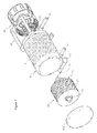
- a vehicle power generation system using exhaust gas which comprises a casing 10 which is installed at a vehicle chassis and is formed of an inlet hole 11 for inputting an exhaust gas and an outlet hole 12 for discharging an exhaust gas; a turbine 20 which is rotatably installed in the interior of the casing 10 and rotates by means of a pressure of the exhaust gas inputted into the inlet hole 11; a power generator 30 which has a rotatary shaft 31 axially engaged to a shaft part 21 of the turbine 20 passing through a front side of the casing 10; and a fixing bracket 40 for fixing the power generator 30 to the casing 10, wherein said inlet hole 11 is obliquely formed at a side portion of a front side of the casing 10, and said turbine 20 includes a shaft part 21 rotatably engaged to a bearing installed in the front and rear sides of the casing 10 and a wing assembly 22 rotated by a pressure of the exhaust gas inputted into the inlet hole 11, and said wing assembly 22 includes a pluralit
- the vehicle electric power generation system using an exhaust system of the present invention it is possible to generate electric power using exhaust gas without using an additional energy input since a turbine is rotated by means of an exhaust gas discharged from an engine, and the electric power is generated as the turbine drives the electric power generator.
- the turbine is formed of a plurality of wing disks equipped with latch wings being opposite to a plurality of inlet holes, so the turbine can be efficiently rotated by means of the exhaust gas, so that the electric power generator can be effectively driven for thereby generating a lot of electric power energy.
- Figure 1 is a perspective view of a vehicle power generation system using exhaust gas according to the present invention
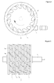
- Figure 2 is a front view of a wing disk belonging to a turbine of Figure 1
- Figure 3 is a front view of a partition disk belonging to a turbine of Figure 1
- Figure 4 is a view for explaining an inlet hole and a wing disk obliquely formed at a side portion of a casing in Figure 1
- Figure 5 is a side view of a turbine of Figure 1 .
- the vehicle power generation system using exhausting gas is installed a chassis of a vehicle, which includes a casing 10 which is installed at a vehicle chassis and is formed of an inlet hole 11 for inputting an exhaust gas and an outlet hole 12 for discharging an exhaust gas; a turbine 20 which is rotatably installed in the interior of the casing 10 and rotates by means of a pressure of the exhaust gas inputted into the inlet hole 11; a power generator 30 which has a rotary shaft 31 axially engaged to a shaft part 21 of the turbine 20 passing through a front side of the casing 10; and a fixing bracket 40 for fixing the power generator 30 to the casing 10.
- the casing 10 is formed in a cylindrical shape which is fixed to a fixing part of a chassis of a vehicle. As shown in Figures 1 and 4 , an inlet hole 11 is obliquely formed in a side portion of a front side of the casing 10 for inputting exhaust gas, and an outlet hole 12 is formed in a rear side of the casing 10 for discharging exhaust gas which has been used for rotating the turbine 20. Since the inlet hole 11 is obliquely formed, so the exhaust gas inputted into the inlet hole 11 can effectively rotate the turbine 20. At this time, the inlet hole 11 is connected with a muffler which finally discharges exhaust gas, and the outlet hole 12 is connected with an additional pipe.
- the inlet hole 11 might be connected with an exhaust manifold which exhausts exhaust from engine, and the outlet hole 12 may be connected with muffler.
- a bracket 13 is formed in the casing 10 and is engaged by means of a bolt and a nut to be fixed to a chassis of a vehicle.
- a plurality of radiation fins 15 are formed in an outer surface of the casing 10 for radiating heat which is generated by means of a high speed rotation of a turbine 20.
- the radiation fins 15 can be integrally formed when forming the casing 10 in a cylindrical shape or can be separately formed and engaged to the casing 10.
- the turbine 20 includes a shaft part 21 rotatably engaged to a bearing(not shown) installed in the front and rear sides of the casing 10, and a wing assembly 22 which is engaged to the shaft part 21 and rotates by means of a pressure of the exhaust gas inputted into the inlet hole 11.
- the wing assembly 22 may be formed in various forms, and in the embodiment of the present invention, the wing assembly 22 includes a plurality of wing disks 23 with a plurality of latch wings 23a being opposite to the direction of the inlet hole 11, and a partition disk 24 which partitions the wing disk 23 and other wing disk 23'.
- the front side of the latch 23a formed in the wing disk 23 is formed in a latch shape toward the inlet hole 11 for an easier rotation by means of an exhaust gas inputted into the inlet hole 11, and the rear side of the same is obliquely formed.
- a plurality of holes are formed in the partition disk 24 for discharging exhaust gas, and two holes 24a and 24b are preferably formed for easier description of the present invention. It is preferred that the holes 24a and 24b are obliquely formed when the thickness of the partition disk 24 is thick, and the inclination direction is toward the rotation direction of the turbine.
- the wing assembly is constituted in a structure that a plurality of wing disks 23 and a plurality of partition disks 24 are stacked in the shaft part 21.
- the wing assembly 22 is partitioned by means of the partition disk 24' of the front side in which four wing disks 23 are stacked in the direction of the inlet hole 11, and two wing disks 23 are stacked in the side of the outlet hole 12 and are partitioned by the partition disk 24" of the rear side, and a plurality of partition disks partition a plurality of wing disks stacked between the partition disk 24' of the front side and the partition disk 24" of the rear side partition.
- the latch wings 23a are arranged in spiral shape, and the holes 24a and 24b formed in the partition disks 24, 24' and 24" partitioning the wing disks are arranged in spiral shapes between the latch wings 23a.
- the exhaust gas inputted into the inlet hole 11 pushes and rotates the latch wings 23a disposed as being opposite and in spiral shapes, and the exhaust gas is discharged through the outlet hole 12 through the holes 24a and 24b and the latch wing 23a formed in the partition disk 24 arranged in spiral shape.
- the exhaust gas pushes the latch wings 23a disposed in a spiral shape and passes through the other latch wings and the spiral holes 24a and 24b of the partition disk and pass through the outlet hole 12 for thereby effectively rotating the turbine 20.
- the rotating turbine 20 rotates the rotor of the power generator 20 for thereby producing a lot of electric power.
- the fixing bracket 40 integrally fixes the power generator 30 to the casing 10.
Landscapes
- Engineering & Computer Science (AREA)
- Chemical & Material Sciences (AREA)
- Mechanical Engineering (AREA)
- General Engineering & Computer Science (AREA)
- Combustion & Propulsion (AREA)
- Chemical Kinetics & Catalysis (AREA)
- General Chemical & Material Sciences (AREA)
- Oil, Petroleum & Natural Gas (AREA)
- Engine Equipment That Uses Special Cycles (AREA)
- Cooling, Air Intake And Gas Exhaust, And Fuel Tank Arrangements In Propulsion Units (AREA)
- Exhaust Silencers (AREA)
- Supercharger (AREA)
Abstract
Description
- The present invention relates to a vehicle power generation system using exhaust gas, and in particular to a vehicle power generation system using exhaust gas which generates electric power used for electrolysis as the system is used in a vehicle which uses a mixed gas of hydrogen and oxygen.
- A hydrogen-oxygen mixed gas generation apparatus is constituted to generate hydrogen and oxygen which are obtained as water is electrolysis-treated. The above apparatus generates a mixed gas of hydrogen and oxygen which is a non-pollution energy source by supplying water mixed with a small amount of electrolyte into an electrolysis tank equipped with a positive (+) electrode and a negative (-) electrode and applying a DC voltage thereto.
- At this time, the hydrogen and oxygen are produced at a molecular ration of 2:1, and hydrogen is produced in a form of bubble from the surface of the electrode (-), and oxygen is produced in a form of bubble from the surface of the electrode (+). The produced hydrogen and oxygen are mixed and become a mixed gas which is combustible. In casing of burning, any pollutants are not produced, so the hydrogen and oxygen gases are considered as an environment friendly energy source.
- The applicant of the present invention has tried to apply such hydrogen and oxygen mixed gas generation apparatus to a vehicle for thereby generating hydrogen and oxygen mixed gas and has researched to use the same as a fuel for driving an engine.
- In order to generate a mixed gas of hydrogen and oxygen, it is needed to supply a couple of tens to hundreds of amperes to the electrodes (-) and (+). However, it seems difficult for the battery or generator installed in the vehicle to receive such currents.
- Accordingly, it is an object of the present invention to provide a vehicle power generation system using exhaust gas which is able to generate an electric energy using exhaust gas of a vehicle for the use of generating a mixed gas of hydrogen and oxygen.
- To achieve the above objects, there is provided a vehicle power generation system using exhaust gas which comprises a
casing 10 which is installed at a vehicle chassis and is formed of aninlet hole 11 for inputting an exhaust gas and anoutlet hole 12 for discharging an exhaust gas; aturbine 20 which is rotatably installed in the interior of thecasing 10 and rotates by means of a pressure of the exhaust gas inputted into theinlet hole 11; apower generator 30 which has arotatary shaft 31 axially engaged to ashaft part 21 of theturbine 20 passing through a front side of thecasing 10; and afixing bracket 40 for fixing thepower generator 30 to thecasing 10, wherein saidinlet hole 11 is obliquely formed at a side portion of a front side of thecasing 10, and saidturbine 20 includes ashaft part 21 rotatably engaged to a bearing installed in the front and rear sides of thecasing 10 and awing assembly 22 rotated by a pressure of the exhaust gas inputted into theinlet hole 11, and saidwing assembly 22 includes a plurality ofwing disks 23 with a plurality oflatch wings 23a being opposite to theinlet hole 11, and saidwing assembly 22 is partitioned by a partition disk 24' of a front side after thewing disks 23 are stacked in the direction of theinlet hole 11, and a plurality ofwing disks 23 are stacked at the side of theinlet hole 12, and it is partitioned at thepartition disk 24" of the rear side, and a plurality of partition disks partition a plurality of wings stacked between the partition disk 24' of the font side and thepartition disk 24" of the rear side, and in thestacked wing disks 23, saidlatch wings 23a are arranged in a spiral shape, andholes partition disks latch wings 23a in spiral shapes. - There are further provided a plurality of radiation fins 15 formed on an outer surface of the
casing 10 for externally radiating the heat generated by means of a high speed rotation of theturbine 20. - According to the vehicle electric power generation system using an exhaust system of the present invention, it is possible to generate electric power using exhaust gas without using an additional energy input since a turbine is rotated by means of an exhaust gas discharged from an engine, and the electric power is generated as the turbine drives the electric power generator.
- In addition, since the turbine is formed of a plurality of wing disks equipped with latch wings being opposite to a plurality of inlet holes, so the turbine can be efficiently rotated by means of the exhaust gas, so that the electric power generator can be effectively driven for thereby generating a lot of electric power energy.
- The present invention will become better understood with reference to the accompanying drawings which are given only by way of illustration and thus are not limitative of the present invention, wherein;
-
Figure 1 is a perspective view of a vehicle power generation system using exhaust gas according to the present invention; -
Figure 2 is a front view of a wing disk belonging to a turbine ofFigure 1 ; -
Figure 3 is a front view of a partition disk belonging to a turbine ofFigure 1 ; -
Figure 4 is a view for explaining an inlet hole and a wing disk obliquely formed at a side portion of a casing inFigure 1 ; -
Figure 5 is a side view of a turbine ofFigure 1 . -
10: casing 11: inlet hole 12: outlet hole 13: bracket 15: radiation fin 20: turbine 21: shaft part 22: wing assembly 23: wing disk 23a: latch wing 24: partition disk 24a, 24b: hole 30: power generator 40: fixing bracket - The vehicle power generation system using exhaust gas according to the present invention will be described with reference to the accompanying drawings.
-
Figure 1 is a perspective view of a vehicle power generation system using exhaust gas according to the present invention;Figure 2 is a front view of a wing disk belonging to a turbine ofFigure 1 ;Figure 3 is a front view of a partition disk belonging to a turbine ofFigure 1 ;Figure 4 is a view for explaining an inlet hole and a wing disk obliquely formed at a side portion of a casing inFigure 1 ; andFigure 5 is a side view of a turbine ofFigure 1 . - As shown therein, the vehicle power generation system using exhausting gas according to the present invention is installed a chassis of a vehicle, which includes a
casing 10 which is installed at a vehicle chassis and is formed of aninlet hole 11 for inputting an exhaust gas and anoutlet hole 12 for discharging an exhaust gas; aturbine 20 which is rotatably installed in the interior of thecasing 10 and rotates by means of a pressure of the exhaust gas inputted into theinlet hole 11; apower generator 30 which has arotary shaft 31 axially engaged to ashaft part 21 of theturbine 20 passing through a front side of thecasing 10; and afixing bracket 40 for fixing thepower generator 30 to thecasing 10. Thecasing 10 is formed in a cylindrical shape which is fixed to a fixing part of a chassis of a vehicle. As shown inFigures 1 and4 , aninlet hole 11 is obliquely formed in a side portion of a front side of thecasing 10 for inputting exhaust gas, and anoutlet hole 12 is formed in a rear side of thecasing 10 for discharging exhaust gas which has been used for rotating theturbine 20. Since theinlet hole 11 is obliquely formed, so the exhaust gas inputted into theinlet hole 11 can effectively rotate theturbine 20. At this time, theinlet hole 11 is connected with a muffler which finally discharges exhaust gas, and theoutlet hole 12 is connected with an additional pipe. Here, theinlet hole 11 might be connected with an exhaust manifold which exhausts exhaust from engine, and theoutlet hole 12 may be connected with muffler. Abracket 13 is formed in thecasing 10 and is engaged by means of a bolt and a nut to be fixed to a chassis of a vehicle. A plurality of radiation fins 15 are formed in an outer surface of thecasing 10 for radiating heat which is generated by means of a high speed rotation of aturbine 20. Here, the radiation fins 15 can be integrally formed when forming thecasing 10 in a cylindrical shape or can be separately formed and engaged to thecasing 10. Theturbine 20 includes ashaft part 21 rotatably engaged to a bearing(not shown) installed in the front and rear sides of thecasing 10, and awing assembly 22 which is engaged to theshaft part 21 and rotates by means of a pressure of the exhaust gas inputted into theinlet hole 11. Thewing assembly 22 may be formed in various forms, and in the embodiment of the present invention, thewing assembly 22 includes a plurality ofwing disks 23 with a plurality oflatch wings 23a being opposite to the direction of theinlet hole 11, and apartition disk 24 which partitions thewing disk 23 and other wing disk 23'. As shown inFigure 4 , the front side of thelatch 23a formed in thewing disk 23 is formed in a latch shape toward theinlet hole 11 for an easier rotation by means of an exhaust gas inputted into theinlet hole 11, and the rear side of the same is obliquely formed. In addition, a plurality of holes are formed in thepartition disk 24 for discharging exhaust gas, and twoholes holes partition disk 24 is thick, and the inclination direction is toward the rotation direction of the turbine. The wing assembly is constituted in a structure that a plurality ofwing disks 23 and a plurality ofpartition disks 24 are stacked in theshaft part 21. In the present embodiment, thewing assembly 22 is partitioned by means of the partition disk 24' of the front side in which fourwing disks 23 are stacked in the direction of theinlet hole 11, and twowing disks 23 are stacked in the side of theoutlet hole 12 and are partitioned by thepartition disk 24" of the rear side, and a plurality of partition disks partition a plurality of wing disks stacked between the partition disk 24' of the front side and thepartition disk 24" of the rear side partition. At this time, in thewing disks 23 stacked, thelatch wings 23a are arranged in spiral shape, and theholes partition disks latch wings 23a. With the structure of theturbine 20, the exhaust gas inputted into theinlet hole 11 pushes and rotates thelatch wings 23a disposed as being opposite and in spiral shapes, and the exhaust gas is discharged through theoutlet hole 12 through theholes latch wing 23a formed in thepartition disk 24 arranged in spiral shape. Namely, the exhaust gas pushes thelatch wings 23a disposed in a spiral shape and passes through the other latch wings and thespiral holes outlet hole 12 for thereby effectively rotating theturbine 20. The rotatingturbine 20 rotates the rotor of thepower generator 20 for thereby producing a lot of electric power. Thefixing bracket 40 integrally fixes thepower generator 30 to thecasing 10. With the above structure, the exhaust gas discharged from the engine is inputted into the interior of thecasing 10 through theinlet holes 11 for thereby rotating theturbine 20, and theturbine 20 generates a lot of power as theturbine 20 drives thepower generator 30. The generated electric power is supplied to the electrodes of the apparatus for generating a mixed gas of hydrogen and oxygen for the use of water electrolysis. - The present invention has been described with reference to the embodiments disclosed in the drawings, which is for the illustrative purpose, and those who skilled in the art can change and modify the disclosed inventions.
Claims (2)
- A vehicle power generation system using exhaust gas, comprising:a casing (10) which is installed at a vehicle chassis and is formed of an inlet hole (11) for inputting an exhaust gas and an outlet hole (12) for discharging an exhaust gas;a turbine (20) which is rotatably installed in the interior of the casing (10) and rotates by means of a pressure of the exhaust gas inputted into the inlet hole (11);a power generator (30) which has a rotary shaft (31) axially engaged to a shaft part (21) of the turbine (20) passing through a front side of the casing (10); anda fixing bracket (40) for fixing the power generator (30) to the casing (10),wherein said inlet hole (11) is obliquely formed at a side portion of a front side of the casing (10), and said turbine (20) includes a shaft part (21) rotatably engaged to a bearing installed in the front and rear sides of the casing (10) and a wing assembly (22) rotated by a pressure of the exhaust gas inputted into the inlet hole (11), and said wing assembly (22) includes a plurality of wing disks (23) with a plurality of latch wings (23a) being opposite to the inlet hole (11), and said wing assembly (22) is partitioned by a partition disk (24') of a front side after the wing disks (23) are stacked in the direction of the inlet hole (11), and a plurality of wing disks (23) are stacked at the side of the inlet hole (12), and it is partitioned at the partition disk (24") of the rear side, and a plurality of partition disks partition a plurality of wings stacked between the partition disk (24') of the font side and the partition disk (24") of the rear side, and in the stacked wing disks (23), said latch wings (23a) are arranged in a spiral shape, and holes (24a and 24b) formed in the partition disks (24, 24' and 24") are disposed between the latch wings (23a) in spiral shapes.
- The system of claim 1, further comprising a plurality of radiation fins (15) formed on an outer surface of the casing (10) for externally radiating the heat generated by means of a high speed rotation of the turbine (20).
Applications Claiming Priority (1)
| Application Number | Priority Date | Filing Date | Title |
|---|---|---|---|
| KR1020090034530A KR100934174B1 (en) | 2009-04-21 | 2009-04-21 | A exhaust gas driving generator |
Publications (2)
| Publication Number | Publication Date |
|---|---|
| EP2246540A1 true EP2246540A1 (en) | 2010-11-03 |
| EP2246540B1 EP2246540B1 (en) | 2011-12-21 |
Family
ID=41684794
Family Applications (1)
| Application Number | Title | Priority Date | Filing Date |
|---|---|---|---|
| EP10275043A Not-in-force EP2246540B1 (en) | 2009-04-21 | 2010-04-16 | Vehicle power generation system using exhaust gas |
Country Status (8)
| Country | Link |
|---|---|
| US (1) | US20110072813A1 (en) |
| EP (1) | EP2246540B1 (en) |
| JP (1) | JP2010255632A (en) |
| KR (1) | KR100934174B1 (en) |
| AT (1) | ATE538291T1 (en) |
| AU (1) | AU2010201555A1 (en) |
| BR (1) | BRPI1001198A2 (en) |
| TW (1) | TW201040390A (en) |
Cited By (1)
| Publication number | Priority date | Publication date | Assignee | Title |
|---|---|---|---|---|
| CN108798847A (en) * | 2018-06-27 | 2018-11-13 | 崔秀萍 | A kind of power generator and method of new-energy automobile |
Families Citing this family (2)
| Publication number | Priority date | Publication date | Assignee | Title |
|---|---|---|---|---|
| CN102900494A (en) * | 2012-09-27 | 2013-01-30 | 张美玲 | Car exhaust purifying and generating device |
| KR101315404B1 (en) * | 2013-08-09 | 2013-10-18 | 임동섭 | Apparatus for power generation using exhaust gas |
Citations (3)
| Publication number | Priority date | Publication date | Assignee | Title |
|---|---|---|---|---|
| GB187492A (en) * | 1921-11-28 | 1922-10-26 | Ivor Jones | Improvements in apparatus for utilizing and silencing the exhaust of internal combustion engines |
| JPS58190511A (en) * | 1982-04-30 | 1983-11-07 | Hino Motors Ltd | Engine muffler |
| US6434936B1 (en) * | 2000-04-25 | 2002-08-20 | Daljit Singh | Super diesel apparatus |
Family Cites Families (13)
| Publication number | Priority date | Publication date | Assignee | Title |
|---|---|---|---|---|
| JPS505745A (en) * | 1973-05-21 | 1975-01-21 | ||
| JPH0772481B2 (en) * | 1986-07-15 | 1995-08-02 | 満博 金尾 | Turbine |
| JPH0481502A (en) * | 1989-12-09 | 1992-03-16 | Yasuro Nakanishi | Turbine and turbocharger using it |
| JP3354976B2 (en) * | 1991-10-17 | 2002-12-09 | 株式会社荏原製作所 | Screw rotor and method of manufacturing the same |
| JPH05195808A (en) * | 1992-01-21 | 1993-08-03 | Mitsui Eng & Shipbuild Co Ltd | Screw engine |
| JPH06101671A (en) * | 1992-09-21 | 1994-04-12 | Kobe Steel Ltd | Screw rotor |
| JPH11187618A (en) * | 1997-12-24 | 1999-07-09 | Aisin Seiki Co Ltd | Turbogenerator |
| GB2355768B (en) * | 1999-11-01 | 2004-03-17 | Kofi Abaka Jackson | Compressor or turbine rotor having spirally curved blades |
| JP3738725B2 (en) * | 2001-11-02 | 2006-01-25 | トヨタ自動車株式会社 | Exhaust energy recovery device for combustion engine |
| US6604360B1 (en) * | 2002-04-18 | 2003-08-12 | Deere & Company | Exhaust driven engine cooling system |
| TWM247694U (en) * | 2002-11-12 | 2004-10-21 | Guo-Lin Huang | Exhaust pipe with illuminating effect |
| KR20040095488A (en) * | 2003-05-09 | 2004-11-15 | 삼성테크윈 주식회사 | Disk for gas turbine engine |
| KR20050096604A (en) * | 2004-03-31 | 2005-10-06 | 삼성테크윈 주식회사 | Turbine shroud assembly |
-
2009
- 2009-04-21 KR KR1020090034530A patent/KR100934174B1/en active IP Right Grant
-
2010
- 2010-04-15 US US12/798,985 patent/US20110072813A1/en not_active Abandoned
- 2010-04-16 BR BRPI1001198-6A2A patent/BRPI1001198A2/en not_active Application Discontinuation
- 2010-04-16 EP EP10275043A patent/EP2246540B1/en not_active Not-in-force
- 2010-04-16 AT AT10275043T patent/ATE538291T1/en active
- 2010-04-16 TW TW099111997A patent/TW201040390A/en unknown
- 2010-04-19 AU AU2010201555A patent/AU2010201555A1/en not_active Abandoned
- 2010-04-20 JP JP2010097179A patent/JP2010255632A/en active Pending
Patent Citations (3)
| Publication number | Priority date | Publication date | Assignee | Title |
|---|---|---|---|---|
| GB187492A (en) * | 1921-11-28 | 1922-10-26 | Ivor Jones | Improvements in apparatus for utilizing and silencing the exhaust of internal combustion engines |
| JPS58190511A (en) * | 1982-04-30 | 1983-11-07 | Hino Motors Ltd | Engine muffler |
| US6434936B1 (en) * | 2000-04-25 | 2002-08-20 | Daljit Singh | Super diesel apparatus |
Cited By (1)
| Publication number | Priority date | Publication date | Assignee | Title |
|---|---|---|---|---|
| CN108798847A (en) * | 2018-06-27 | 2018-11-13 | 崔秀萍 | A kind of power generator and method of new-energy automobile |
Also Published As
| Publication number | Publication date |
|---|---|
| KR100934174B1 (en) | 2009-12-29 |
| JP2010255632A (en) | 2010-11-11 |
| AU2010201555A1 (en) | 2010-11-04 |
| ATE538291T1 (en) | 2012-01-15 |
| TW201040390A (en) | 2010-11-16 |
| EP2246540B1 (en) | 2011-12-21 |
| BRPI1001198A2 (en) | 2014-02-18 |
| US20110072813A1 (en) | 2011-03-31 |
Similar Documents
| Publication | Publication Date | Title |
|---|---|---|
| CN106948969B (en) | Mixed propulsion system | |
| JP5570614B2 (en) | Efficiency improving turbine | |
| JP2011520707A (en) | Aircraft powered by a hybrid power source | |
| EP2246540B1 (en) | Vehicle power generation system using exhaust gas | |
| EP1826366A1 (en) | Electric energy generating system | |
| CN101191436A (en) | Automobile engine exhausting turbine electricity generation device | |
| CN103441291B (en) | The air supply of fuel cell system and energy recycle device | |
| US20080286102A1 (en) | Roof fans generating vehicle | |
| JP2003097411A (en) | Wind power generation device for vehicle | |
| WO2016043810A1 (en) | Water-rotor-internal-combustion engine (wrice) | |
| KR101239277B1 (en) | Wind power generator | |
| JP6614621B2 (en) | Wind power generator and vehicle equipped with the same | |
| KR102464682B1 (en) | Hydrogen generating apparatus with self-generation function using centrifugal force | |
| CN205977401U (en) | Modular generating set | |
| JP2011144793A (en) | Mounted-type wind pressure power generation system | |
| ES2304226B1 (en) | MECHANICAL MOVEMENT GENERATOR SYSTEM FOR THE PRODUCTION OF ELECTRICAL ENERGY THROUGH THE APPLICATION AND COMBUSTION OF HYDROGEN. | |
| JP3207631U (en) | Axial flow exhaust generator | |
| CN102852711B (en) | Laminar rotating-wing wind turbine | |
| JP7199413B2 (en) | Micro combustion device for power generation | |
| CN207658074U (en) | A kind of hybrid power unmanned vehicle using exhaust continuation of the journey | |
| KR101713233B1 (en) | Blower systems for power generation using turbines | |
| Kumar et al. | Aerodynamic simulation, thermal and fuel consumption analysis of hydrogen powered fuel cell vehicle | |
| KR20190080675A (en) | A Propellator that Achieves Momentum by Disassembling and Burning Water with Laser Light and Photocatalyst | |
| KR20100023294A (en) | An independent power plant | |
| JP2014066251A (en) | Wind power generation electric vehicle |
Legal Events
| Date | Code | Title | Description |
|---|---|---|---|
| PUAI | Public reference made under article 153(3) epc to a published international application that has entered the european phase |
Free format text: ORIGINAL CODE: 0009012 |
|
| AK | Designated contracting states |
Kind code of ref document: A1 Designated state(s): AT BE BG CH CY CZ DE DK EE ES FI FR GB GR HR HU IE IS IT LI LT LU LV MC MK MT NL NO PL PT RO SE SI SK SM TR |
|
| AX | Request for extension of the european patent |
Extension state: AL BA ME RS |
|
| 17P | Request for examination filed |
Effective date: 20110503 |
|
| GRAP | Despatch of communication of intention to grant a patent |
Free format text: ORIGINAL CODE: EPIDOSNIGR1 |
|
| RIC1 | Information provided on ipc code assigned before grant |
Ipc: F01D 1/02 20060101ALI20110520BHEP Ipc: F01N 5/04 20060101AFI20110520BHEP |
|
| GRAS | Grant fee paid |
Free format text: ORIGINAL CODE: EPIDOSNIGR3 |
|
| GRAA | (expected) grant |
Free format text: ORIGINAL CODE: 0009210 |
|
| AK | Designated contracting states |
Kind code of ref document: B1 Designated state(s): AT BE BG CH CY CZ DE DK EE ES FI FR GB GR HR HU IE IS IT LI LT LU LV MC MK MT NL NO PL PT RO SE SI SK SM TR |
|
| REG | Reference to a national code |
Ref country code: GB Ref legal event code: FG4D |
|
| REG | Reference to a national code |
Ref country code: CH Ref legal event code: EP |
|
| REG | Reference to a national code |
Ref country code: AT Ref legal event code: REF Ref document number: 538291 Country of ref document: AT Kind code of ref document: T Effective date: 20120115 |
|
| REG | Reference to a national code |
Ref country code: IE Ref legal event code: FG4D |
|
| REG | Reference to a national code |
Ref country code: DE Ref legal event code: R096 Ref document number: 602010000527 Country of ref document: DE Effective date: 20120301 |
|
| REG | Reference to a national code |
Ref country code: NL Ref legal event code: VDEP Effective date: 20111221 |
|
| PG25 | Lapsed in a contracting state [announced via postgrant information from national office to epo] |
Ref country code: NO Free format text: LAPSE BECAUSE OF FAILURE TO SUBMIT A TRANSLATION OF THE DESCRIPTION OR TO PAY THE FEE WITHIN THE PRESCRIBED TIME-LIMIT Effective date: 20120321 Ref country code: LT Free format text: LAPSE BECAUSE OF FAILURE TO SUBMIT A TRANSLATION OF THE DESCRIPTION OR TO PAY THE FEE WITHIN THE PRESCRIBED TIME-LIMIT Effective date: 20111221 |
|
| LTIE | Lt: invalidation of european patent or patent extension |
Effective date: 20111221 |
|
| PG25 | Lapsed in a contracting state [announced via postgrant information from national office to epo] |
Ref country code: SI Free format text: LAPSE BECAUSE OF FAILURE TO SUBMIT A TRANSLATION OF THE DESCRIPTION OR TO PAY THE FEE WITHIN THE PRESCRIBED TIME-LIMIT Effective date: 20111221 Ref country code: SE Free format text: LAPSE BECAUSE OF FAILURE TO SUBMIT A TRANSLATION OF THE DESCRIPTION OR TO PAY THE FEE WITHIN THE PRESCRIBED TIME-LIMIT Effective date: 20111221 Ref country code: LV Free format text: LAPSE BECAUSE OF FAILURE TO SUBMIT A TRANSLATION OF THE DESCRIPTION OR TO PAY THE FEE WITHIN THE PRESCRIBED TIME-LIMIT Effective date: 20111221 Ref country code: GR Free format text: LAPSE BECAUSE OF FAILURE TO SUBMIT A TRANSLATION OF THE DESCRIPTION OR TO PAY THE FEE WITHIN THE PRESCRIBED TIME-LIMIT Effective date: 20120322 Ref country code: NL Free format text: LAPSE BECAUSE OF FAILURE TO SUBMIT A TRANSLATION OF THE DESCRIPTION OR TO PAY THE FEE WITHIN THE PRESCRIBED TIME-LIMIT Effective date: 20111221 Ref country code: HR Free format text: LAPSE BECAUSE OF FAILURE TO SUBMIT A TRANSLATION OF THE DESCRIPTION OR TO PAY THE FEE WITHIN THE PRESCRIBED TIME-LIMIT Effective date: 20111221 |
|
| PG25 | Lapsed in a contracting state [announced via postgrant information from national office to epo] |
Ref country code: CY Free format text: LAPSE BECAUSE OF FAILURE TO SUBMIT A TRANSLATION OF THE DESCRIPTION OR TO PAY THE FEE WITHIN THE PRESCRIBED TIME-LIMIT Effective date: 20111221 Ref country code: BE Free format text: LAPSE BECAUSE OF FAILURE TO SUBMIT A TRANSLATION OF THE DESCRIPTION OR TO PAY THE FEE WITHIN THE PRESCRIBED TIME-LIMIT Effective date: 20111221 |
|
| PG25 | Lapsed in a contracting state [announced via postgrant information from national office to epo] |
Ref country code: BG Free format text: LAPSE BECAUSE OF FAILURE TO SUBMIT A TRANSLATION OF THE DESCRIPTION OR TO PAY THE FEE WITHIN THE PRESCRIBED TIME-LIMIT Effective date: 20120321 Ref country code: SK Free format text: LAPSE BECAUSE OF FAILURE TO SUBMIT A TRANSLATION OF THE DESCRIPTION OR TO PAY THE FEE WITHIN THE PRESCRIBED TIME-LIMIT Effective date: 20111221 Ref country code: EE Free format text: LAPSE BECAUSE OF FAILURE TO SUBMIT A TRANSLATION OF THE DESCRIPTION OR TO PAY THE FEE WITHIN THE PRESCRIBED TIME-LIMIT Effective date: 20111221 Ref country code: CZ Free format text: LAPSE BECAUSE OF FAILURE TO SUBMIT A TRANSLATION OF THE DESCRIPTION OR TO PAY THE FEE WITHIN THE PRESCRIBED TIME-LIMIT Effective date: 20111221 Ref country code: IS Free format text: LAPSE BECAUSE OF FAILURE TO SUBMIT A TRANSLATION OF THE DESCRIPTION OR TO PAY THE FEE WITHIN THE PRESCRIBED TIME-LIMIT Effective date: 20120421 |
|
| PGFP | Annual fee paid to national office [announced via postgrant information from national office to epo] |
Ref country code: DE Payment date: 20120427 Year of fee payment: 3 |
|
| PG25 | Lapsed in a contracting state [announced via postgrant information from national office to epo] |
Ref country code: PT Free format text: LAPSE BECAUSE OF FAILURE TO SUBMIT A TRANSLATION OF THE DESCRIPTION OR TO PAY THE FEE WITHIN THE PRESCRIBED TIME-LIMIT Effective date: 20120423 Ref country code: PL Free format text: LAPSE BECAUSE OF FAILURE TO SUBMIT A TRANSLATION OF THE DESCRIPTION OR TO PAY THE FEE WITHIN THE PRESCRIBED TIME-LIMIT Effective date: 20111221 Ref country code: RO Free format text: LAPSE BECAUSE OF FAILURE TO SUBMIT A TRANSLATION OF THE DESCRIPTION OR TO PAY THE FEE WITHIN THE PRESCRIBED TIME-LIMIT Effective date: 20111221 |
|
| PGFP | Annual fee paid to national office [announced via postgrant information from national office to epo] |
Ref country code: FR Payment date: 20120601 Year of fee payment: 3 |
|
| REG | Reference to a national code |
Ref country code: AT Ref legal event code: MK05 Ref document number: 538291 Country of ref document: AT Kind code of ref document: T Effective date: 20111221 |
|
| PLBE | No opposition filed within time limit |
Free format text: ORIGINAL CODE: 0009261 |
|
| STAA | Information on the status of an ep patent application or granted ep patent |
Free format text: STATUS: NO OPPOSITION FILED WITHIN TIME LIMIT |
|
| PG25 | Lapsed in a contracting state [announced via postgrant information from national office to epo] |
Ref country code: DK Free format text: LAPSE BECAUSE OF FAILURE TO SUBMIT A TRANSLATION OF THE DESCRIPTION OR TO PAY THE FEE WITHIN THE PRESCRIBED TIME-LIMIT Effective date: 20111221 |
|
| 26N | No opposition filed |
Effective date: 20120924 |
|
| PG25 | Lapsed in a contracting state [announced via postgrant information from national office to epo] |
Ref country code: IT Free format text: LAPSE BECAUSE OF FAILURE TO SUBMIT A TRANSLATION OF THE DESCRIPTION OR TO PAY THE FEE WITHIN THE PRESCRIBED TIME-LIMIT Effective date: 20111221 Ref country code: MC Free format text: LAPSE BECAUSE OF NON-PAYMENT OF DUE FEES Effective date: 20120430 |
|
| REG | Reference to a national code |
Ref country code: IE Ref legal event code: MM4A |
|
| REG | Reference to a national code |
Ref country code: DE Ref legal event code: R097 Ref document number: 602010000527 Country of ref document: DE Effective date: 20120924 |
|
| PG25 | Lapsed in a contracting state [announced via postgrant information from national office to epo] |
Ref country code: IE Free format text: LAPSE BECAUSE OF NON-PAYMENT OF DUE FEES Effective date: 20120416 Ref country code: AT Free format text: LAPSE BECAUSE OF FAILURE TO SUBMIT A TRANSLATION OF THE DESCRIPTION OR TO PAY THE FEE WITHIN THE PRESCRIBED TIME-LIMIT Effective date: 20111221 |
|
| PG25 | Lapsed in a contracting state [announced via postgrant information from national office to epo] |
Ref country code: MK Free format text: LAPSE BECAUSE OF FAILURE TO SUBMIT A TRANSLATION OF THE DESCRIPTION OR TO PAY THE FEE WITHIN THE PRESCRIBED TIME-LIMIT Effective date: 20111221 |
|
| PG25 | Lapsed in a contracting state [announced via postgrant information from national office to epo] |
Ref country code: ES Free format text: LAPSE BECAUSE OF FAILURE TO SUBMIT A TRANSLATION OF THE DESCRIPTION OR TO PAY THE FEE WITHIN THE PRESCRIBED TIME-LIMIT Effective date: 20120401 |
|
| PG25 | Lapsed in a contracting state [announced via postgrant information from national office to epo] |
Ref country code: FI Free format text: LAPSE BECAUSE OF FAILURE TO SUBMIT A TRANSLATION OF THE DESCRIPTION OR TO PAY THE FEE WITHIN THE PRESCRIBED TIME-LIMIT Effective date: 20111221 |
|
| PG25 | Lapsed in a contracting state [announced via postgrant information from national office to epo] |
Ref country code: MT Free format text: LAPSE BECAUSE OF FAILURE TO SUBMIT A TRANSLATION OF THE DESCRIPTION OR TO PAY THE FEE WITHIN THE PRESCRIBED TIME-LIMIT Effective date: 20111221 |
|
| PG25 | Lapsed in a contracting state [announced via postgrant information from national office to epo] |
Ref country code: DE Free format text: LAPSE BECAUSE OF NON-PAYMENT OF DUE FEES Effective date: 20131101 |
|
| REG | Reference to a national code |
Ref country code: FR Ref legal event code: ST Effective date: 20131231 |
|
| REG | Reference to a national code |
Ref country code: DE Ref legal event code: R119 Ref document number: 602010000527 Country of ref document: DE Effective date: 20131101 |
|
| PG25 | Lapsed in a contracting state [announced via postgrant information from national office to epo] |
Ref country code: FR Free format text: LAPSE BECAUSE OF NON-PAYMENT OF DUE FEES Effective date: 20130430 |
|
| PG25 | Lapsed in a contracting state [announced via postgrant information from national office to epo] |
Ref country code: TR Free format text: LAPSE BECAUSE OF FAILURE TO SUBMIT A TRANSLATION OF THE DESCRIPTION OR TO PAY THE FEE WITHIN THE PRESCRIBED TIME-LIMIT Effective date: 20111221 |
|
| PG25 | Lapsed in a contracting state [announced via postgrant information from national office to epo] |
Ref country code: LU Free format text: LAPSE BECAUSE OF NON-PAYMENT OF DUE FEES Effective date: 20120416 Ref country code: SM Free format text: LAPSE BECAUSE OF FAILURE TO SUBMIT A TRANSLATION OF THE DESCRIPTION OR TO PAY THE FEE WITHIN THE PRESCRIBED TIME-LIMIT Effective date: 20111221 |
|
| PG25 | Lapsed in a contracting state [announced via postgrant information from national office to epo] |
Ref country code: HU Free format text: LAPSE BECAUSE OF FAILURE TO SUBMIT A TRANSLATION OF THE DESCRIPTION OR TO PAY THE FEE WITHIN THE PRESCRIBED TIME-LIMIT Effective date: 20100416 |
|
| REG | Reference to a national code |
Ref country code: CH Ref legal event code: PL |
|
| GBPC | Gb: european patent ceased through non-payment of renewal fee |
Effective date: 20140416 |
|
| PG25 | Lapsed in a contracting state [announced via postgrant information from national office to epo] |
Ref country code: CH Free format text: LAPSE BECAUSE OF NON-PAYMENT OF DUE FEES Effective date: 20140430 Ref country code: LI Free format text: LAPSE BECAUSE OF NON-PAYMENT OF DUE FEES Effective date: 20140430 Ref country code: GB Free format text: LAPSE BECAUSE OF NON-PAYMENT OF DUE FEES Effective date: 20140416 |