EP2246282A1 - Method for moving a reel of packaging material from a storage station to a supply station of a packaging unit for producing sealed packages of food product, and clamping unit for clamping such reel - Google Patents
Method for moving a reel of packaging material from a storage station to a supply station of a packaging unit for producing sealed packages of food product, and clamping unit for clamping such reel Download PDFInfo
- Publication number
- EP2246282A1 EP2246282A1 EP20090159101 EP09159101A EP2246282A1 EP 2246282 A1 EP2246282 A1 EP 2246282A1 EP 20090159101 EP20090159101 EP 20090159101 EP 09159101 A EP09159101 A EP 09159101A EP 2246282 A1 EP2246282 A1 EP 2246282A1
- Authority
- EP
- European Patent Office
- Prior art keywords
- reel
- clamping
- unit
- supply station
- packaging
- Prior art date
- Legal status (The legal status is an assumption and is not a legal conclusion. Google has not performed a legal analysis and makes no representation as to the accuracy of the status listed.)
- Granted
Links
Images


Classifications
-
- B—PERFORMING OPERATIONS; TRANSPORTING
- B65—CONVEYING; PACKING; STORING; HANDLING THIN OR FILAMENTARY MATERIAL
- B65H—HANDLING THIN OR FILAMENTARY MATERIAL, e.g. SHEETS, WEBS, CABLES
- B65H19/00—Changing the web roll
- B65H19/10—Changing the web roll in unwinding mechanisms or in connection with unwinding operations
- B65H19/12—Lifting, transporting, or inserting the web roll; Removing empty core
-
- B—PERFORMING OPERATIONS; TRANSPORTING
- B60—VEHICLES IN GENERAL
- B60P—VEHICLES ADAPTED FOR LOAD TRANSPORTATION OR TO TRANSPORT, TO CARRY, OR TO COMPRISE SPECIAL LOADS OR OBJECTS
- B60P3/00—Vehicles adapted to transport, to carry or to comprise special loads or objects
- B60P3/035—Vehicles adapted to transport, to carry or to comprise special loads or objects for transporting reel units
-
- B—PERFORMING OPERATIONS; TRANSPORTING
- B65—CONVEYING; PACKING; STORING; HANDLING THIN OR FILAMENTARY MATERIAL
- B65H—HANDLING THIN OR FILAMENTARY MATERIAL, e.g. SHEETS, WEBS, CABLES
- B65H2301/00—Handling processes for sheets or webs
- B65H2301/40—Type of handling process
- B65H2301/41—Winding, unwinding
- B65H2301/417—Handling or changing web rolls
- B65H2301/4171—Handling web roll
- B65H2301/4172—Handling web roll by circumferential portion, e.g. rolling on circumference
- B65H2301/41722—Handling web roll by circumferential portion, e.g. rolling on circumference by acting on outer surface, e.g. gripping or clamping
-
- B—PERFORMING OPERATIONS; TRANSPORTING
- B65—CONVEYING; PACKING; STORING; HANDLING THIN OR FILAMENTARY MATERIAL
- B65H—HANDLING THIN OR FILAMENTARY MATERIAL, e.g. SHEETS, WEBS, CABLES
- B65H2301/00—Handling processes for sheets or webs
- B65H2301/40—Type of handling process
- B65H2301/41—Winding, unwinding
- B65H2301/417—Handling or changing web rolls
- B65H2301/4171—Handling web roll
- B65H2301/4173—Handling web roll by central portion, e.g. gripping central portion
-
- B—PERFORMING OPERATIONS; TRANSPORTING
- B65—CONVEYING; PACKING; STORING; HANDLING THIN OR FILAMENTARY MATERIAL
- B65H—HANDLING THIN OR FILAMENTARY MATERIAL, e.g. SHEETS, WEBS, CABLES
- B65H2301/00—Handling processes for sheets or webs
- B65H2301/40—Type of handling process
- B65H2301/41—Winding, unwinding
- B65H2301/417—Handling or changing web rolls
- B65H2301/4171—Handling web roll
- B65H2301/4174—Handling web roll by side portion, e.g. forwarding roll lying on side portion
Definitions
- the present invention relates to a method for moving a reel of packaging material from a storage station to a supply station of a packaging unit for producing sealed packages of food product.
- the present invention relates to a clamping unit for clamping a reel of packaging material.
- Tetra Brik Aseptic registered trademark
- a typical example of this type of package is the parallelepiped-shaped package for liquid or pourable food products known as Tetra Brik Aseptic (registered trademark), which is made by folding and sealing laminated strip packaging material.
- the packaging material has a multilayer structure substantially comprising a base layer for stiffness and strength, which may be defined by a layer of fibrous material, e.g. paper, or mineral-filled polypropylene material; and a number of layers of heat-seal plastic material, e.g. polyethylene film, covering both sides of the base layer.
- a base layer for stiffness and strength which may be defined by a layer of fibrous material, e.g. paper, or mineral-filled polypropylene material; and a number of layers of heat-seal plastic material, e.g. polyethylene film, covering both sides of the base layer.
- the packaging material also comprises a layer of gas- and light-barrier material, e.g. aluminium foil or ethyl vinyl alcohol (EVOH) film, which is superimposed on a layer of heat-seal plastic material, and is in turn covered with another layer of heat-seal plastic material forming the inner face of the package eventually contacting the food product.
- gas- and light-barrier material e.g. aluminium foil or ethyl vinyl alcohol (EVOH) film
- packages of this sort are produced on fully automatic packaging units having a supply station fed with reels of packaging material.
- a continuous tube is formed from the web-fed packaging material in the packaging unit; the web of packaging material is sterilized in the packaging unit, e.g. by applying a chemical sterilizing agent such as a hydrogen peroxide solution, which is subsequently removed, e.g. by heating and evaporation, from the surfaces of the packaging material.
- a chemical sterilizing agent such as a hydrogen peroxide solution
- the sterilized web is maintained in a closed, sterile environment, and is folded into a cylinder and sealed longitudinally to form a tube.
- the tube is fed in a first vertical direction parallel to its axis, is filled continuously with the sterilized or sterile-processed food product and is heat-sealed at equally spaced cross sections by two pairs of jaws to form pillow packs each having a top and a bottom transverse sealing band, i.e. a band extending along a second direction orthogonal to the first direction.
- Pillow packs are separated by cutting respective sealing bands and are then fed to a folding station, in which they are fold so as to form respective packages.
- Reels of packaging materials are normally stored onto a pallet at the storage station and are subsequently taken from such pallet and loaded into the supply station of the packaging unit.
- a first manipulator takes the reel from the storage station and a second manipulator takes the reel having its axis along a horizontal direction and feeds the supply station with such reel.
- the second manipulator comprises a loading equipment to correctly arrange the reel inside the supply station of the packaging unit.
- a method for moving a reel of packaging material from a storage station to a supply station of a packaging unit for producing sealed packages of food product as claimed in Claim 1.
- the present invention also relates to a clamping unit for clamping a reel of packaging material, as claimed in claim 9.
- Number 1 in Figures 1 to 7 indicates as a whole a clamping unit for moving a reel 2 of packaging material from a storage station 3 (only schematically shown in Figure 2 ) to a supply station 4 ( Figure 6 ) of a packaging unit 5 for producing sealed packages of food product from a tube of sheet packaging material.
- reel 2 comprises an outer circumferential peripheral edge 6, a central through hole 7 radially inner with respect to peripheral edge 6, and a pair of head surfaces 9 opposite one another and extending from hole 7 to peripheral edge 6.
- Hole 7 is also coaxial to reel 2 ( Figure 2 ).
- reels 2 are stacked at storage station 3 preferably on a pallet and have their axes extending along a vertical direction ( Figure 2 ).
- each reel 2 is fed to supply station 4 with the respective axis extending along a horizontal direction ( Figure 6 ).
- supply station 4 substantially comprises a frame 11 defining a compartment 12 into which reel 2 is fitted.
- reel 2 is supported within compartment 12 by a spindle 18 in a rotatable manner about its own axis.
- spindle 18 ( Figures 4 and 5 ) comprises a pair of cylindrical central portions 20 (only one of which is shown in Figure 7 ) coaxially housed within hole 7 of reel 2 and a pair of cylindrical projections 23 extending on respective opposite sides of portions 20.
- Each projection 23 has diameter lower than the diameter of portions 20 and comprises an annular groove 24 and an end 26 arranged on the opposite side of groove 24 with respect to corresponding portion 20.
- Packaging unit 5 preferably produces sealed packages of a pourable food product, such as pasteurized or UHT milk, fruit juice, wine, etc.
- Packaging unit 5 may also produce sealed packages of a food product which is pourable into tube when producing packages, and sets after packages are sealed.
- a food product is a portion of cheese, which is melted when producing packages, and sets after packages are sealed.
- the packaging material has a multilayer structure (not shown) and comprises a layer of fibrous material, normally paper, covered on both sides with respective layers of heat-seal plastic material, e.g. polyethylene.
- the packaging material also comprises a layer of gas- and light-barrier material, e.g. aluminium foil or ethyl vinyl alcohol (EVOH) film, which is superimposed on a layer of heat-seal plastic material, and is in turn covered with another layer of heat-seal plastic material forming the inner face of package eventually contacting the food product.
- gas- and light-barrier material e.g. aluminium foil or ethyl vinyl alcohol (EVOH) film
- Tube is formed in known manner by longitudinally folding and sealing a web (not shown) of heat-seal sheet material, is filled by a fill pipe (not shown) with the sterilized or sterile-processed food product for packaging, and is fed, in known manner not shown, along a vertical path, is heat-sealed and cut at equally spaced cross sections.
- Clamping unit 1 is preferably carried by a lift truck 8 which is shown in Figure 6 .
- Clamping unit 1 advantageously comprises a pair of clamping arms 10 movable relatively to one another along a direction X (horizontal in Figures 1 , 2 , 6 and 7 ; and vertical in Figures 3 to 5 ) to any of: an open position in which they are detached from reel 2, a first clamping position ( Figures 2 to 5 ) in which they are at first distance and cooperate with edge 6 of reel 2, and a second clamping position ( Figure 6 ) in which they are at second distance lower than said first distance and grip a spindle 18 engaging hole 7 of reel 2; clamping arms 10 are rotatable integrally to one another about a direction Y transversal to direction X.
- the first distance equals the diameter of reel 2.
- clamping arms 10 When clamping arms 10 are in the open position, they are at a third distance greater than the first distance.
- Clamping arms 10 are substantially parallel. Furthermore, clamping arms 10 are movable integrally to one another along a direction Z vertical in use and transversal to both directions X, Y.
- Direction Y, Z are fixed with respect to the movement of clamping arms 10 among open position, first clamping position and second clamping position.
- Direction X is integral with clamping arms 10 and is orthogonal to direction Y, Z when the axis of clamped reel 2 is horizontal ( Figures 2 and 6 ); direction X is parallel to direction Z and orthogonal to direction Y when the axis of clamped reel 2 is vertical ( Figures 3 to 5 ).
- clamping unit 1 substantially comprises:
- Each clamping arm 10 comprises a substantially trapezoidal portion 13 adjacent to table 17 and a free portion 14 opposed to trapezoidal portion 13 with respect to table 17.
- Free portion 14 is substantially rectangular with a seat 19 configured to couple with a relative groove 24 of spindle 18.
- seat 19 is through and U-shaped.
- Free portion 14 of each clamping arm 10 also comprises an elastomeric pad 21 adapted to cooperate with edge 6 of reel 2.
- pad 21 is located on the side of free portion 14 of each clamping arm 10 facing the other clamping arm 10.
- Pad 21 of each clamping arm 10 is also arranged between respective trapezoidal portion 13 and respective seat 19 along direction Y.
- Clamping unit 1 also comprises a pair of variable length actuators 22 arranged each between ends adjacent to table 17 of respective trapezoidal portions 11.
- Actuators 22 substantially extend parallel to table 17 and orthogonal to clamping arms 10, and are operated to change the distance of clamping arms 10 along direction X.
- clamping arms 10 move away from one another along direction X when the length of actuators 22 is extended. Differently, clamping arms 10 approach one another along direction X when the length of actuators 22 is reduced.
- clamping unit 1 will be hereinafter described starting from the configuration shown in Figure 2 , in which clamping unit 1 carried by lift truck 8 removes reel 2 from storage station 3.
- reels 2 are stored at storage station 3 with their own axes horizontal.
- clamping arms 10 are moved from open position to the first clamping position and cooperate with edge 6 of reel 2.
- direction X is horizontal and orthogonal to directions Y, Z ( Figure 2 ).
- clamping arms 10 are rotated integrally with one another and with reel 2 about axis Y for an angle of ninety degrees in a first sense.
- the axis of reel 2 is horizontal and direction X is parallel to direction Z and orthogonal to direction Y. In other words, direction X is vertical.
- portions 20 are manually inserted within the hole 7 of reel 2 so that projections 23 extend on opposite sides of hole 7 ( Figure 3 ).
- Clamping arms 10 are then lowered ( Figure 4 ) together with reel 2 along direction Z until reel 2 is supported by a stand 30 ( Figure 5 ).
- stand 30 substantially comprises a horizontal a base 35 and a pair of projections 36 projecting upwards from base 35. Projections 36 define respective grooves 37.
- Clamping arms 10 are then moved to open position and are rotated about axis Y of ninety degrees relative to reel 2 in a second sense opposite to the first sense. At the end of the rotation, direction X is horizontal.
- clamping arms 10 are moved to the second clamping position and seats 19 cooperate with grooves 24 of spindle 18.
- clamping arms 10 are raised along direction Z and raise reel 2 together with spindle 18.
- Lift truck 8 moves reel 2 to supply station 4 of packaging unit 5 and is then inserted within compartment 12 ( Figure 6 ).
- reel 2 is mounted together with spindle 18 on a support within compartment 12, clamping arms 10 are moved to the open position and lift truck 8 moves away from supply station 4.
- clamping unit 1 uses same clamping arms 10 both for taking reel 2 from storage station 3 and for feeding supply station 4 with such reel 2.
- spindle 18 is clamped by clamping arms 10 while edge 6 of reel 2 is not clamped.
- clamping unit 1 does not require the presence of a loading equipment to correctly arrange reel 2 within compartment 12.
Landscapes
- Basic Packing Technique (AREA)
- Replacement Of Web Rolls (AREA)
- Supplying Of Containers To The Packaging Station (AREA)
- Package Closures (AREA)
- Auxiliary Devices For And Details Of Packaging Control (AREA)
Abstract
Description
- The present invention relates to a method for moving a reel of packaging material from a storage station to a supply station of a packaging unit for producing sealed packages of food product.
- Furthermore, the present invention relates to a clamping unit for clamping a reel of packaging material.
- Many food products, such as fruit juice, pasteurized or UHT (ultra-high-temperature treated) milk, wine, tomato sauce, etc., are sold in packages made of sterilized packaging material.
- A typical example of this type of package is the parallelepiped-shaped package for liquid or pourable food products known as Tetra Brik Aseptic (registered trademark), which is made by folding and sealing laminated strip packaging material.
- The packaging material has a multilayer structure substantially comprising a base layer for stiffness and strength, which may be defined by a layer of fibrous material, e.g. paper, or mineral-filled polypropylene material; and a number of layers of heat-seal plastic material, e.g. polyethylene film, covering both sides of the base layer.
- In the case of aseptic packages for long-storage products, such as UHT milk, the packaging material also comprises a layer of gas- and light-barrier material, e.g. aluminium foil or ethyl vinyl alcohol (EVOH) film, which is superimposed on a layer of heat-seal plastic material, and is in turn covered with another layer of heat-seal plastic material forming the inner face of the package eventually contacting the food product.
- As is known, packages of this sort are produced on fully automatic packaging units having a supply station fed with reels of packaging material.
- In particular, a continuous tube is formed from the web-fed packaging material in the packaging unit; the web of packaging material is sterilized in the packaging unit, e.g. by applying a chemical sterilizing agent such as a hydrogen peroxide solution, which is subsequently removed, e.g. by heating and evaporation, from the surfaces of the packaging material.
- The sterilized web is maintained in a closed, sterile environment, and is folded into a cylinder and sealed longitudinally to form a tube.
- The tube is fed in a first vertical direction parallel to its axis, is filled continuously with the sterilized or sterile-processed food product and is heat-sealed at equally spaced cross sections by two pairs of jaws to form pillow packs each having a top and a bottom transverse sealing band, i.e. a band extending along a second direction orthogonal to the first direction. Pillow packs are separated by cutting respective sealing bands and are then fed to a folding station, in which they are fold so as to form respective packages.
- Reels of packaging materials are normally stored onto a pallet at the storage station and are subsequently taken from such pallet and loaded into the supply station of the packaging unit.
- More precisely, a first manipulator takes the reel from the storage station and a second manipulator takes the reel having its axis along a horizontal direction and feeds the supply station with such reel. The second manipulator comprises a loading equipment to correctly arrange the reel inside the supply station of the packaging unit.
- A need is felt within the industry to streamline as much as possible the taking of reels from the pallet and the subsequent loading of reels onto the supply station.
- Furthermore, a need is felt within the industry to reduce as much as possible the risk of damaging the external layer of packaging material as the reel is loaded onto the supply station.
- Finally, due to the restriction of space within the supply station, a need is felt within the industry to facilitate the loading of reels onto the supply station.
- It is an object of the present invention to provide a method for moving a reel of packaging material and a clamping unit for clamping such reel of packaging material, designed to meet at least one of the above requirement in a straightforward, low-cost manner.
- According to the present invention, there is provided a method for moving a reel of packaging material from a storage station to a supply station of a packaging unit for producing sealed packages of food product, as claimed in Claim 1.
- The present invention also relates to a clamping unit for clamping a reel of packaging material, as claimed in
claim 9. - A preferred, non-limiting embodiment of the present invention will be described by way of example with reference to the accompanying drawings, in which:
-
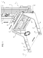
Figure 1 is a perspective view of a clamping unit according to the present invention; -
Figures 2 to 5 are perspective views of the clamping unit ofFigure 1 in respective operative positions; -
Figure 6 is a lateral view in a reduced scale of the clamping unit ofFigures 1 to 5 in a further operative position and of a supply station of a packaging unit; and -
Figure 7 is perspective view of the clamping unit ofFigures 1 to 6 when coupled with a spindle. - Number 1 in
Figures 1 to 7 indicates as a whole a clamping unit for moving areel 2 of packaging material from a storage station 3 (only schematically shown inFigure 2 ) to a supply station 4 (Figure 6 ) of apackaging unit 5 for producing sealed packages of food product from a tube of sheet packaging material. - In particular,
reel 2 comprises an outer circumferentialperipheral edge 6, a central through hole 7 radially inner with respect toperipheral edge 6, and a pair ofhead surfaces 9 opposite one another and extending from hole 7 toperipheral edge 6. Hole 7 is also coaxial to reel 2 (Figure 2 ). - Furthermore,
reels 2 are stacked at storage station 3 preferably on a pallet and have their axes extending along a vertical direction (Figure 2 ). - Differently, each
reel 2 is fed to supplystation 4 with the respective axis extending along a horizontal direction (Figure 6 ). - With reference to
Figure 6 ,supply station 4 substantially comprises aframe 11 defining acompartment 12 into whichreel 2 is fitted. - More precisely,
reel 2 is supported withincompartment 12 by aspindle 18 in a rotatable manner about its own axis. - In particular, spindle 18 (
Figures 4 and5 ) comprises a pair of cylindrical central portions 20 (only one of which is shown inFigure 7 ) coaxially housed within hole 7 ofreel 2 and a pair ofcylindrical projections 23 extending on respective opposite sides ofportions 20. - Each
projection 23 has diameter lower than the diameter ofportions 20 and comprises anannular groove 24 and anend 26 arranged on the opposite side ofgroove 24 with respect tocorresponding portion 20. -
Packaging unit 5 preferably produces sealed packages of a pourable food product, such as pasteurized or UHT milk, fruit juice, wine, etc. -
Packaging unit 5 may also produce sealed packages of a food product which is pourable into tube when producing packages, and sets after packages are sealed. One example of such a food product is a portion of cheese, which is melted when producing packages, and sets after packages are sealed. - The packaging material has a multilayer structure (not shown) and comprises a layer of fibrous material, normally paper, covered on both sides with respective layers of heat-seal plastic material, e.g. polyethylene. In the case of aseptic packages for long-storage products, such as UHT milk, the packaging material also comprises a layer of gas- and light-barrier material, e.g. aluminium foil or ethyl vinyl alcohol (EVOH) film, which is superimposed on a layer of heat-seal plastic material, and is in turn covered with another layer of heat-seal plastic material forming the inner face of package eventually contacting the food product.
- Tube is formed in known manner by longitudinally folding and sealing a web (not shown) of heat-seal sheet material, is filled by a fill pipe (not shown) with the sterilized or sterile-processed food product for packaging, and is fed, in known manner not shown, along a vertical path, is heat-sealed and cut at equally spaced cross sections.
- Clamping unit 1 is preferably carried by a lift truck 8 which is shown in
Figure 6 . - Clamping unit 1 advantageously comprises a pair of clamping
arms 10 movable relatively to one another along a direction X (horizontal inFigures 1 ,2 ,6 and7 ; and vertical inFigures 3 to 5 ) to any of: an open position in which they are detached fromreel 2, a first clamping position (Figures 2 to 5 ) in which they are at first distance and cooperate withedge 6 ofreel 2, and a second clamping position (Figure 6 ) in which they are at second distance lower than said first distance and grip aspindle 18 engaging hole 7 ofreel 2; clampingarms 10 are rotatable integrally to one another about a direction Y transversal to direction X. - In particular, the first distance equals the diameter of
reel 2. - When clamping
arms 10 are in the open position, they are at a third distance greater than the first distance. - Clamping
arms 10 are substantially parallel. Furthermore, clampingarms 10 are movable integrally to one another along a direction Z vertical in use and transversal to both directions X, Y. - Direction Y, Z are fixed with respect to the movement of clamping
arms 10 among open position, first clamping position and second clamping position. - Direction X is integral with clamping
arms 10 and is orthogonal to direction Y, Z when the axis ofclamped reel 2 is horizontal (Figures 2 and6 ); direction X is parallel to direction Z and orthogonal to direction Y when the axis ofclamped reel 2 is vertical (Figures 3 to 5 ). - In greater detail, clamping unit 1 substantially comprises:
- a pair of
vertical guides 15 fitted to lift vehicle 8; - a
slide 16 which may slide along direction Z ontoguides 15; - a supporting table 17 which may rotate about direction Y with respect to slide 16 and protrudingly bears, on the opposite side of
guides 15 andslide 16, clampingarms 10. - Each
clamping arm 10 comprises a substantiallytrapezoidal portion 13 adjacent to table 17 and afree portion 14 opposed totrapezoidal portion 13 with respect to table 17. -
Free portion 14 is substantially rectangular with aseat 19 configured to couple with arelative groove 24 ofspindle 18. Preferably,seat 19 is through and U-shaped. -
Free portion 14 of eachclamping arm 10 also comprises anelastomeric pad 21 adapted to cooperate withedge 6 ofreel 2. - In particular,
pad 21 is located on the side offree portion 14 of eachclamping arm 10 facing theother clamping arm 10. -
Pad 21 of eachclamping arm 10 is also arranged between respectivetrapezoidal portion 13 andrespective seat 19 along direction Y. - Clamping unit 1 also comprises a pair of
variable length actuators 22 arranged each between ends adjacent to table 17 of respectivetrapezoidal portions 11. -
Actuators 22 substantially extend parallel to table 17 and orthogonal to clampingarms 10, and are operated to change the distance of clampingarms 10 along direction X. - More precisely, clamping
arms 10 move away from one another along direction X when the length ofactuators 22 is extended. Differently, clampingarms 10 approach one another along direction X when the length ofactuators 22 is reduced. - The operation of clamping unit 1 will be hereinafter described starting from the configuration shown in
Figure 2 , in which clamping unit 1 carried by lift truck 8 removesreel 2 from storage station 3. - More precisely,
reels 2 are stored at storage station 3 with their own axes horizontal. - As clamping unit 1 removes
reel 2 from storage station 3, clampingarms 10 are moved from open position to the first clamping position and cooperate withedge 6 ofreel 2. - In this position, direction X is horizontal and orthogonal to directions Y, Z (
Figure 2 ). - Afterwards, clamping
arms 10 are rotated integrally with one another and withreel 2 about axis Y for an angle of ninety degrees in a first sense. At the end of the rotation, the axis ofreel 2 is horizontal and direction X is parallel to direction Z and orthogonal to direction Y. In other words, direction X is vertical. - At this stage,
portions 20 are manually inserted within the hole 7 ofreel 2 so thatprojections 23 extend on opposite sides of hole 7 (Figure 3 ). - Clamping
arms 10 are then lowered (Figure 4 ) together withreel 2 along direction Z untilreel 2 is supported by a stand 30 (Figure 5 ). - More precisely, stand 30 substantially comprises a horizontal a
base 35 and a pair ofprojections 36 projecting upwards frombase 35.Projections 36 definerespective grooves 37. - When
reel 2 is supported bystand 30,grooves 37 are engaged byend 26 ofspindle 18. - Clamping
arms 10 are then moved to open position and are rotated about axis Y of ninety degrees relative to reel 2 in a second sense opposite to the first sense. At the end of the rotation, direction X is horizontal. - Furthermore, clamping
arms 10 are moved to the second clamping position and seats 19 cooperate withgrooves 24 ofspindle 18. - Afterwards, clamping
arms 10 are raised along direction Z and raisereel 2 together withspindle 18. Lift truck 8moves reel 2 to supplystation 4 ofpackaging unit 5 and is then inserted within compartment 12 (Figure 6 ). - Finally,
reel 2 is mounted together withspindle 18 on a support withincompartment 12, clampingarms 10 are moved to the open position and lift truck 8 moves away fromsupply station 4. - The advantages of clamping unit 1 and of the method of moving a reel according to the present invention will be clear from the foregoing description.
- In particular, clamping unit 1 uses same clamping
arms 10 both for takingreel 2 from storage station 3 and for feedingsupply station 4 withsuch reel 2. - As a consequence, the movement of
reel 2 from storage station 3 to supplystation 4 is highly streamlined. - Furthermore, as
reel 2 is fed to supplystation 4,spindle 18 is clamped by clampingarms 10 whileedge 6 ofreel 2 is not clamped. - Accordingly, there is substantially no risk of damaging the external layer of packaging
material defining edge 6 during the insertion ofreel 2. - Furthermore, due to the fact that
spindle 18 is inserted within hole 7 ofreel 2, the centering ofreel 2 within thecompartment 12 is favoured. - Finally, clamping unit 1 does not require the presence of a loading equipment to correctly arrange
reel 2 withincompartment 12. - Clearly, changes may be made to clamping unit 1 and of the method of moving a reel as described and illustrated herein without, however, departing from the scope of the present invention as defined in the accompanying claims.
Claims (15)
- A method for moving a reel (2) of packaging material from a storage station (3) to a supply station (4) of a packaging unit (5), characterized by comprising the steps of:- clamping a peripheral edge (6) of said reel (2) by using a pair of clamping elements (10) of a clamping unit (1);- rotating said clamping elements (10) relatively to said reel (2); and- supporting said reel (2) on said pair of clamping elements (10) by interacting with a portion (7) of said reel (2) radially inner with respect to said circumferential edge (6).
- A method as claimed in claim 1, characterized in comprising the step of supporting said reel (2) on a stand (30) after said step of clamping a circumferential edge (6) of said reel (2) and before said step of rotating said clamping elements (10).
- A method as claimed in claim 1 or 2, characterized in comprising the step of taking said reel (2) from said storage station (3) and the step of feeding said supply station (5) with said reel (2);
said step of taking said reel (2) comprising said step of clamping a circumferential edge (6);
said step of feeding being carried out with said reel (2) supported by interacting with said portion (7). - A method as claimed in claims 2 or 3, characterized in comprising the step of inserting a spindle (18) within a hole (7) of said reel (2) radially inner with respect to said peripheral edge (6); said step of inserting being carried out before the step of supporting said reel (2) by interacting with said portion (7); said step of supporting said reel (2) by interacting with said portion (7) comprising the step of gripping said spindle (18) by means of said clamping elements (10).
- A method as claimed in claim 4, characterized in that said step of inserting is carried out before said step of supporting said reel (2) on said stand (30).
- A method as claimed in claim 4 or 5, characterized in that said step of inserting a spindle (18) is carried out manually.
- A method as claimed in anyone of claims 4 to 6, characterized in that said step of feeding said supply station (4) with said reel (2) comprises the step of feeding said supply station (4) with said reel (2) together with said spindle (18).
- A method as claimed in anyone of foregoing claims, characterized by comprising the step of rotating said clamping elements (10) integrally with said reel (2) after said step of clamping said circumferential edge (6) and before said step of rotating said clamping elements (10) relatively to said reel (2).
- A clamping unit (1) for clamping a reel (2) of packaging material, characterized by comprising a pair of clamping elements (10) movable relatively to one another along a first direction (X) in any of:- an open position in which they are detached from said reel (2);- a first clamping position in which they are at a first distance and clamp, in use, a peripheral edge (6) of said reel (2); and- a second clamping position in which they are at a second distance lower than said first distance and support, in use, said reel (2) by interacting with a portion (7) radially inner with respect to said circumferential edge (6);
said clamping elements (10) being rotatable integrally one with respect to another about a second direction (Y) transversal to said first direction (X). - A clamping unit as claimed in claim 9, characterized in that said clamping elements (10) may slide integrally to one another along a third direction (Z) transversal to said second direction (Y).
- A clamping unit as claimed in claim 9 or 10, characterized in that each said clamping element (10) comprises:- a first portion (21) which may cooperate with said peripheral edge (6) of said reel (2) in said first clamping position; and- and a second portion (19) defining a seat (19) so configured to be engageable by a spindle (18) housed within a hole (7) of said reel (2) in said second clamping position.
- A clamping unit as claimed in claim 11, characterized in that said first portion (21) comprises an elastomeric pad (21).
- A clamping unit as claimed in claim 11 or 12, characterized in that said seat (19) is U-shaped.
- A clamping unit as claimed in anyone of claims 10 to 13, characterized by comprising:- at least a guide (15);- at least a slide (16) movable with respect to said guide (15) along said third direction (Z); and- a support table (17) rotatable with respect to said slide (16) about said second direction (Y) and supporting said clamping element (10) in a movable manner with respect to said first direction (X).
- Lift truck (8) for moving a reel (2) of packaging material from a storage station (3) to a supply station (4) of a packaging unit (5), characterized by comprising a clamping unit (1) as claimed in anyone of claims 9 to 14.
Priority Applications (8)
| Application Number | Priority Date | Filing Date | Title |
|---|---|---|---|
| EP09159101.6A EP2246282B1 (en) | 2009-04-29 | 2009-04-29 | Method for moving a reel of packaging material from a storage station to a supply station of a packaging unit for producing sealed packages of food product, and clamping unit for clamping such reel |
| RU2011148425/13A RU2533901C2 (en) | 2009-04-29 | 2010-04-27 | Method of displacement of roll of packing material from storage point to feeding device of packaging machine for manufacturing of tight packing of food products and clamping device for clamping such roll |
| BRPI1013693A BRPI1013693A2 (en) | 2009-04-29 | 2010-04-27 | Method for moving a spool of packing material, clamping unit, and forklift |
| CN201080018929.7A CN102414101B (en) | 2009-04-29 | 2010-04-27 | Method for moving a reel of packaging material and clamping unit for clamping such reel |
| US13/143,822 US9120636B2 (en) | 2009-04-29 | 2010-04-27 | Method for moving a reel of packaging material from a storage station to a supply station of a packaging unit for producing sealed packages of food product, and clamping unit for clamping such reel |
| MX2011009488A MX2011009488A (en) | 2009-04-29 | 2010-04-27 | Method for moving a reel of packaging material from a storage station to a supply station of a packaging unit for producing sealed packages of food product, and clamping unit for clamping such reel. |
| JP2012507712A JP5670432B2 (en) | 2009-04-29 | 2010-04-27 | Method of moving a reel of packaging material from a storage station to a supply station of a packaging unit for producing a sealed package of food and a clamping unit for clamping such a reel |
| PCT/EP2010/055607 WO2010125051A1 (en) | 2009-04-29 | 2010-04-27 | Method for moving a reel of packaging material from a storage station to a supply station of a packaging unit for producing sealed packages of food product, and clamping unit for clamping such reel |
Applications Claiming Priority (1)
| Application Number | Priority Date | Filing Date | Title |
|---|---|---|---|
| EP09159101.6A EP2246282B1 (en) | 2009-04-29 | 2009-04-29 | Method for moving a reel of packaging material from a storage station to a supply station of a packaging unit for producing sealed packages of food product, and clamping unit for clamping such reel |
Publications (3)
| Publication Number | Publication Date |
|---|---|
| EP2246282A1 true EP2246282A1 (en) | 2010-11-03 |
| EP2246282A8 EP2246282A8 (en) | 2011-01-05 |
| EP2246282B1 EP2246282B1 (en) | 2015-11-25 |
Family
ID=41087375
Family Applications (1)
| Application Number | Title | Priority Date | Filing Date |
|---|---|---|---|
| EP09159101.6A Not-in-force EP2246282B1 (en) | 2009-04-29 | 2009-04-29 | Method for moving a reel of packaging material from a storage station to a supply station of a packaging unit for producing sealed packages of food product, and clamping unit for clamping such reel |
Country Status (8)
| Country | Link |
|---|---|
| US (1) | US9120636B2 (en) |
| EP (1) | EP2246282B1 (en) |
| JP (1) | JP5670432B2 (en) |
| CN (1) | CN102414101B (en) |
| BR (1) | BRPI1013693A2 (en) |
| MX (1) | MX2011009488A (en) |
| RU (1) | RU2533901C2 (en) |
| WO (1) | WO2010125051A1 (en) |
Cited By (6)
| Publication number | Priority date | Publication date | Assignee | Title |
|---|---|---|---|---|
| CN103568018A (en) * | 2013-10-15 | 2014-02-12 | 上海星派自动化科技有限公司 | Robot gripper for clamping multi-basket member to overturn |
| CN107696008A (en) * | 2017-09-28 | 2018-02-16 | 浙江大学城市学院 | One kind transport confrontation robot combining structure |
| EP3556694A1 (en) * | 2018-04-16 | 2019-10-23 | Trützschler GmbH & Co. KG | Device for pulling-out winding shafts |
| CN111943023A (en) * | 2020-08-13 | 2020-11-17 | 中国南方电网有限责任公司超高压输电公司大理局 | Converter valve tower hoisting device |
| CN112591539A (en) * | 2020-12-07 | 2021-04-02 | 宣城市安工大工业技术研究院有限公司 | Paper roll feeding and cutting mechanism and using method thereof |
| CN114084788A (en) * | 2021-10-23 | 2022-02-25 | 北京城建集团有限责任公司 | Membrane body hoisting device and method without damaging membrane unit |
Families Citing this family (18)
| Publication number | Priority date | Publication date | Assignee | Title |
|---|---|---|---|---|
| US9637255B2 (en) * | 2012-12-26 | 2017-05-02 | The Raymond Corporation | Palletized load wrapping and transporting vehicle and method |
| US9637366B2 (en) * | 2013-01-08 | 2017-05-02 | Cerro Wire Llc | Reel handling device and method |
| US9132696B2 (en) * | 2015-02-11 | 2015-09-15 | Glg Farms Llc | Tire manipulation system |
| DE102015215815A1 (en) * | 2015-08-19 | 2017-02-23 | Rwe Power Aktiengesellschaft | Device for handling loads |
| CN105128225B (en) * | 2015-10-12 | 2017-08-04 | 核工业理化工程研究院 | Handling turnover device for cylindrical winding mandrel |
| ITUA20163404A1 (en) * | 2016-05-13 | 2017-11-13 | Celli Nonwovens Spa | LINE FOR THE PRODUCTION OF COILS OF RIBBED MATERIAL |
| AU2017288912B2 (en) * | 2016-06-28 | 2020-02-20 | Flexsteel Pipeline Technologies, Inc. | Half-moon lifting device |
| US10981749B2 (en) * | 2016-06-28 | 2021-04-20 | Trinity Bay Equipment Holdings, LLC | Half-moon lifting device |
| US10981765B2 (en) | 2016-06-28 | 2021-04-20 | Trinity Bay Equipment Holdings, LLC | Half-moon lifting device |
| US10118532B2 (en) * | 2016-07-14 | 2018-11-06 | Dejana Truck And Equipment | Reel handler |
| US10589959B2 (en) | 2016-12-05 | 2020-03-17 | Cerro Wire Llc | Driven reel trolley |
| CN108248899B (en) * | 2018-01-04 | 2019-06-04 | 中国科学院沈阳自动化研究所 | A space station laboratory cabinet assembly test operation robot |
| CA3102272C (en) | 2018-06-27 | 2023-05-23 | Kraft Foods Schweiz Holding Gmbh | Apparatus and methods for reel handling |
| US11420338B2 (en) * | 2018-12-27 | 2022-08-23 | Toyota Research Institute, Inc. | Assistive robot systems for container tilting |
| CN113119834B (en) * | 2021-04-19 | 2022-07-01 | 重庆万马汽车制造(集团)有限公司 | Special trailer of coil of strip transportation that security performance is high |
| CN113104545A (en) * | 2021-05-10 | 2021-07-13 | 太原钢运物流股份有限公司 | Conveying device for improving safe conveying performance of steel coil and using method thereof |
| DE102021125133A1 (en) | 2021-09-28 | 2023-03-30 | Krones Aktiengesellschaft | Mobile robot and method for changing label rolls on a labeling unit |
| IT202200019863A1 (en) * | 2022-09-27 | 2024-03-27 | Sacmi Tech S P A | METHOD AND SYSTEM OF FEEDING PACKAGING MATERIAL TO A PACKAGING MACHINE |
Citations (6)
| Publication number | Priority date | Publication date | Assignee | Title |
|---|---|---|---|---|
| DE9017476U1 (en) * | 1990-12-27 | 1992-04-23 | Maschinenfabrik Alfred Schmermund Gmbh & Co, 5820 Gevelsberg | Device for transferring reels of packaging material |
| US5249757A (en) * | 1990-12-24 | 1993-10-05 | G.D. S.P.A. | Method and device for changing rolls in a machine utilizing strip material |
| EP0664268A2 (en) * | 1994-01-20 | 1995-07-26 | G.D Societa' Per Azioni | Device for feeding reels to a user machine |
| US5618377A (en) * | 1992-12-28 | 1997-04-08 | Tetra Laval Holdings & Finance, S.A. | Film splicer |
| EP0994057A1 (en) * | 1998-10-14 | 2000-04-19 | SASIB TOBACCO S.p.A. | Supply unit of bobbins of wrapping material in a cigarette packing machine and process for pick-up and transfer of the same bobbins |
| DE102006014532A1 (en) * | 2006-03-29 | 2007-10-11 | Koenig & Bauer Aktiengesellschaft | Device for conveying one or more rolls of material with a transport system and a roller gripping device for receiving the roll of material |
Family Cites Families (27)
| Publication number | Priority date | Publication date | Assignee | Title |
|---|---|---|---|---|
| US2971662A (en) * | 1957-12-30 | 1961-02-14 | Clark Equipment Co | Box rotator attachment |
| US3409156A (en) * | 1966-10-05 | 1968-11-05 | Mills Sam | Coil lifter |
| US3511263A (en) * | 1967-10-26 | 1970-05-12 | Cascade Corp | Slack reducer for flexible lines |
| US3830388A (en) * | 1971-07-30 | 1974-08-20 | D Mott | Wheel manipulator |
| US3860193A (en) * | 1973-09-24 | 1975-01-14 | Superior Iron Works & Supply C | Self loading reel carrier |
| US3937413A (en) * | 1974-06-13 | 1976-02-10 | Devine Joseph C | Dual frame rocker trailer |
| US3970342A (en) * | 1975-06-06 | 1976-07-20 | Iowa Mold Tooling Co., Inc. | Tire servicing apparatus |
| US4051966A (en) * | 1975-10-23 | 1977-10-04 | Iowa Mold Tooling Co., Inc. | Tire manipulating apparatus |
| US4354793A (en) * | 1981-02-06 | 1982-10-19 | Mid-America Body & Equipment Co. | Reel locking mechanism for a reel loader apparatus |
| US4447012A (en) * | 1981-03-12 | 1984-05-08 | Woodruff Harold F | Portable reel jack stand |
| JPS5957498U (en) * | 1982-10-05 | 1984-04-14 | 日本テトラパツク株式会社 | Paper reel handling device |
| SE448294B (en) * | 1983-11-17 | 1987-02-09 | Mecanum Ab | Transport device |
| JPH0242691Y2 (en) * | 1985-12-13 | 1990-11-14 | ||
| US4951990A (en) * | 1989-10-03 | 1990-08-28 | The United States Of America As Represented By The Secretary Of The Navy | Fifty five gallon drum handling apparatus |
| IT1235976B (en) | 1989-12-18 | 1992-12-15 | Gd Spa | METHOD AND DEVICE FOR FEEDING AND REPLACEMENT OF REELS IN A PACKAGING MACHINE |
| IT1259440B (en) * | 1992-10-28 | 1996-03-18 | Gd Spa | SYSTEM WITH SEPARATE UNIT FOR THE FEEDING OF TAPE WRAPPING MATERIAL. |
| DE19806432A1 (en) * | 1998-02-17 | 1999-08-19 | Focke & Co | Device for handling bobbins |
| JP2000264507A (en) | 1999-03-19 | 2000-09-26 | Ucc Ueshima Coffee Co Ltd | Portable coil stocker |
| DE60227742D1 (en) * | 2001-05-11 | 2008-09-04 | Gd Spa | Method and device for feeding packaging material to a processing unit |
| US6829835B2 (en) * | 2002-11-21 | 2004-12-14 | Martin Pfeil Trawid-Gmbh | Lifting vehicle |
| RU32754U1 (en) | 2003-04-30 | 2003-09-27 | Богатырев Алексей Борисович | A device for removing from the container the packaging material placed therein for bandaging a stack of sheets |
| CA2480376C (en) * | 2003-09-04 | 2013-04-09 | Justoy Pty Ltd | Article handling apparatus |
| CN100595117C (en) * | 2003-12-01 | 2010-03-24 | 赛鲁迪公司 | Reel changing device and method for implementing a quick reel change |
| GB0500564D0 (en) * | 2005-01-12 | 2005-02-16 | Mechandling Ltd | Roll or reel handling apparatus |
| US7673915B1 (en) * | 2005-02-04 | 2010-03-09 | Fischer Bert M | Coil handling assembly |
| US8096745B2 (en) * | 2007-12-27 | 2012-01-17 | Energy Saving Products & Sales Corp. | Paper roll transport cart |
| EP2258643B1 (en) * | 2009-06-01 | 2015-01-14 | Tetra Laval Holdings & Finance S.A. | Method for feeding a supply station of a packaging unit with a new reel of sheet packaging material, sheet packaging material holder and lift truck |
-
2009
- 2009-04-29 EP EP09159101.6A patent/EP2246282B1/en not_active Not-in-force
-
2010
- 2010-04-27 MX MX2011009488A patent/MX2011009488A/en active IP Right Grant
- 2010-04-27 BR BRPI1013693A patent/BRPI1013693A2/en not_active IP Right Cessation
- 2010-04-27 JP JP2012507712A patent/JP5670432B2/en not_active Expired - Fee Related
- 2010-04-27 RU RU2011148425/13A patent/RU2533901C2/en not_active IP Right Cessation
- 2010-04-27 WO PCT/EP2010/055607 patent/WO2010125051A1/en not_active Ceased
- 2010-04-27 CN CN201080018929.7A patent/CN102414101B/en not_active Expired - Fee Related
- 2010-04-27 US US13/143,822 patent/US9120636B2/en not_active Expired - Fee Related
Patent Citations (6)
| Publication number | Priority date | Publication date | Assignee | Title |
|---|---|---|---|---|
| US5249757A (en) * | 1990-12-24 | 1993-10-05 | G.D. S.P.A. | Method and device for changing rolls in a machine utilizing strip material |
| DE9017476U1 (en) * | 1990-12-27 | 1992-04-23 | Maschinenfabrik Alfred Schmermund Gmbh & Co, 5820 Gevelsberg | Device for transferring reels of packaging material |
| US5618377A (en) * | 1992-12-28 | 1997-04-08 | Tetra Laval Holdings & Finance, S.A. | Film splicer |
| EP0664268A2 (en) * | 1994-01-20 | 1995-07-26 | G.D Societa' Per Azioni | Device for feeding reels to a user machine |
| EP0994057A1 (en) * | 1998-10-14 | 2000-04-19 | SASIB TOBACCO S.p.A. | Supply unit of bobbins of wrapping material in a cigarette packing machine and process for pick-up and transfer of the same bobbins |
| DE102006014532A1 (en) * | 2006-03-29 | 2007-10-11 | Koenig & Bauer Aktiengesellschaft | Device for conveying one or more rolls of material with a transport system and a roller gripping device for receiving the roll of material |
Cited By (8)
| Publication number | Priority date | Publication date | Assignee | Title |
|---|---|---|---|---|
| CN103568018A (en) * | 2013-10-15 | 2014-02-12 | 上海星派自动化科技有限公司 | Robot gripper for clamping multi-basket member to overturn |
| CN103568018B (en) * | 2013-10-15 | 2015-09-09 | 上海星派自动化科技有限公司 | For clamping the robot gripper of many baskets of part upsets |
| CN107696008A (en) * | 2017-09-28 | 2018-02-16 | 浙江大学城市学院 | One kind transport confrontation robot combining structure |
| EP3556694A1 (en) * | 2018-04-16 | 2019-10-23 | Trützschler GmbH & Co. KG | Device for pulling-out winding shafts |
| CN111943023A (en) * | 2020-08-13 | 2020-11-17 | 中国南方电网有限责任公司超高压输电公司大理局 | Converter valve tower hoisting device |
| CN112591539A (en) * | 2020-12-07 | 2021-04-02 | 宣城市安工大工业技术研究院有限公司 | Paper roll feeding and cutting mechanism and using method thereof |
| CN114084788A (en) * | 2021-10-23 | 2022-02-25 | 北京城建集团有限责任公司 | Membrane body hoisting device and method without damaging membrane unit |
| CN114084788B (en) * | 2021-10-23 | 2023-06-23 | 北京城建集团有限责任公司 | Membrane body hoisting device and hoisting method without damaging membrane unit |
Also Published As
| Publication number | Publication date |
|---|---|
| RU2011148425A (en) | 2013-06-10 |
| CN102414101B (en) | 2015-02-25 |
| JP5670432B2 (en) | 2015-02-18 |
| EP2246282A8 (en) | 2011-01-05 |
| JP2012525306A (en) | 2012-10-22 |
| RU2533901C2 (en) | 2014-11-27 |
| CN102414101A (en) | 2012-04-11 |
| BRPI1013693A2 (en) | 2016-04-26 |
| EP2246282B1 (en) | 2015-11-25 |
| MX2011009488A (en) | 2011-10-11 |
| US20110274527A1 (en) | 2011-11-10 |
| US9120636B2 (en) | 2015-09-01 |
| WO2010125051A1 (en) | 2010-11-04 |
Similar Documents
| Publication | Publication Date | Title |
|---|---|---|
| EP2246282B1 (en) | Method for moving a reel of packaging material from a storage station to a supply station of a packaging unit for producing sealed packages of food product, and clamping unit for clamping such reel | |
| EP2258643B1 (en) | Method for feeding a supply station of a packaging unit with a new reel of sheet packaging material, sheet packaging material holder and lift truck | |
| JP2012525306A5 (en) | ||
| US8707662B2 (en) | Packaging machine | |
| JP2018529588A (en) | Method and mounting head for mounting a lid on a container | |
| US20200001518A1 (en) | Guiding device | |
| JP2023535414A (en) | PACKAGE FORMING UNIT, PACKAGING APPARATUS HAVING PACKAGE FORMING UNIT AND PACKAGE FORMING METHOD | |
| JP7374110B2 (en) | Web alignment device, packaging machine with web alignment device, and splicing method | |
| US11434097B2 (en) | Magazine unit for a packaging machine, packaging machine having a magazine unit and method for loading a magazine unit | |
| HK1169090A (en) | Method for moving a reel of packaging material from a storage station to a supply station of a packaging unit for producing sealed packages of food product, and clamping unit for clamping such reel | |
| EP4506288A1 (en) | Support device for a reel, packaging machine having a support device for a reel, method for coupling a reel to a support device and method for uncoupling a reel from a support device | |
| EP4656538A1 (en) | Folding apparatus, packaging machine having a folding apparatus and method for forming finalized packages from semi-finalized packs | |
| EP4527769A1 (en) | Magazine unit for a packaging machine, packaging machine having a magazine unit and method for loading a magazine unit | |
| EP4656539A1 (en) | Folding apparatus, packaging machine having a folding apparatus and method for forming finalized packages from semi-finalized packs | |
| HK1170464A (en) | Method for feeding a supply station of a packaging unit with a new reel of sheet packaging material, sheet packaging material holder and lift truck | |
| CN120659752A (en) | Cartridge unit for a packaging machine, packaging machine with a cartridge unit and method for operating a cartridge unit of a packaging machine | |
| CN114728484A (en) | Unit and method for applying opening devices to a web of packaging material | |
| HK1163625A (en) | Unit for the application of opening devices on packages of food products pourable into a tube of packaging material |
Legal Events
| Date | Code | Title | Description |
|---|---|---|---|
| PUAI | Public reference made under article 153(3) epc to a published international application that has entered the european phase |
Free format text: ORIGINAL CODE: 0009012 |
|
| AK | Designated contracting states |
Kind code of ref document: A1 Designated state(s): AT BE BG CH CY CZ DE DK EE ES FI FR GB GR HR HU IE IS IT LI LT LU LV MC MK MT NL NO PL PT RO SE SI SK TR |
|
| 17P | Request for examination filed |
Effective date: 20110503 |
|
| RAP1 | Party data changed (applicant data changed or rights of an application transferred) |
Owner name: TETRA LAVAL HOLDINGS & FINANCE S.A. |
|
| GRAP | Despatch of communication of intention to grant a patent |
Free format text: ORIGINAL CODE: EPIDOSNIGR1 |
|
| INTG | Intention to grant announced |
Effective date: 20150430 |
|
| GRAS | Grant fee paid |
Free format text: ORIGINAL CODE: EPIDOSNIGR3 |
|
| GRAA | (expected) grant |
Free format text: ORIGINAL CODE: 0009210 |
|
| AK | Designated contracting states |
Kind code of ref document: B1 Designated state(s): AT BE BG CH CY CZ DE DK EE ES FI FR GB GR HR HU IE IS IT LI LT LU LV MC MK MT NL NO PL PT RO SE SI SK TR |
|
| REG | Reference to a national code |
Ref country code: GB Ref legal event code: FG4D |
|
| REG | Reference to a national code |
Ref country code: CH Ref legal event code: EP |
|
| REG | Reference to a national code |
Ref country code: AT Ref legal event code: REF Ref document number: 762476 Country of ref document: AT Kind code of ref document: T Effective date: 20151215 |
|
| REG | Reference to a national code |
Ref country code: IE Ref legal event code: FG4D |
|
| REG | Reference to a national code |
Ref country code: DE Ref legal event code: R096 Ref document number: 602009034922 Country of ref document: DE |
|
| REG | Reference to a national code |
Ref country code: FR Ref legal event code: PLFP Year of fee payment: 8 |
|
| REG | Reference to a national code |
Ref country code: LT Ref legal event code: MG4D |
|
| REG | Reference to a national code |
Ref country code: NL Ref legal event code: MP Effective date: 20160225 |
|
| REG | Reference to a national code |
Ref country code: AT Ref legal event code: MK05 Ref document number: 762476 Country of ref document: AT Kind code of ref document: T Effective date: 20151125 |
|
| PG25 | Lapsed in a contracting state [announced via postgrant information from national office to epo] |
Ref country code: ES Free format text: LAPSE BECAUSE OF FAILURE TO SUBMIT A TRANSLATION OF THE DESCRIPTION OR TO PAY THE FEE WITHIN THE PRESCRIBED TIME-LIMIT Effective date: 20151125 Ref country code: NL Free format text: LAPSE BECAUSE OF FAILURE TO SUBMIT A TRANSLATION OF THE DESCRIPTION OR TO PAY THE FEE WITHIN THE PRESCRIBED TIME-LIMIT Effective date: 20151125 Ref country code: IS Free format text: LAPSE BECAUSE OF FAILURE TO SUBMIT A TRANSLATION OF THE DESCRIPTION OR TO PAY THE FEE WITHIN THE PRESCRIBED TIME-LIMIT Effective date: 20160325 Ref country code: HR Free format text: LAPSE BECAUSE OF FAILURE TO SUBMIT A TRANSLATION OF THE DESCRIPTION OR TO PAY THE FEE WITHIN THE PRESCRIBED TIME-LIMIT Effective date: 20151125 Ref country code: LT Free format text: LAPSE BECAUSE OF FAILURE TO SUBMIT A TRANSLATION OF THE DESCRIPTION OR TO PAY THE FEE WITHIN THE PRESCRIBED TIME-LIMIT Effective date: 20151125 Ref country code: NO Free format text: LAPSE BECAUSE OF FAILURE TO SUBMIT A TRANSLATION OF THE DESCRIPTION OR TO PAY THE FEE WITHIN THE PRESCRIBED TIME-LIMIT Effective date: 20160225 |
|
| PG25 | Lapsed in a contracting state [announced via postgrant information from national office to epo] |
Ref country code: SE Free format text: LAPSE BECAUSE OF FAILURE TO SUBMIT A TRANSLATION OF THE DESCRIPTION OR TO PAY THE FEE WITHIN THE PRESCRIBED TIME-LIMIT Effective date: 20151125 Ref country code: LV Free format text: LAPSE BECAUSE OF FAILURE TO SUBMIT A TRANSLATION OF THE DESCRIPTION OR TO PAY THE FEE WITHIN THE PRESCRIBED TIME-LIMIT Effective date: 20151125 Ref country code: PL Free format text: LAPSE BECAUSE OF FAILURE TO SUBMIT A TRANSLATION OF THE DESCRIPTION OR TO PAY THE FEE WITHIN THE PRESCRIBED TIME-LIMIT Effective date: 20151125 Ref country code: AT Free format text: LAPSE BECAUSE OF FAILURE TO SUBMIT A TRANSLATION OF THE DESCRIPTION OR TO PAY THE FEE WITHIN THE PRESCRIBED TIME-LIMIT Effective date: 20151125 Ref country code: GR Free format text: LAPSE BECAUSE OF FAILURE TO SUBMIT A TRANSLATION OF THE DESCRIPTION OR TO PAY THE FEE WITHIN THE PRESCRIBED TIME-LIMIT Effective date: 20160226 Ref country code: FI Free format text: LAPSE BECAUSE OF FAILURE TO SUBMIT A TRANSLATION OF THE DESCRIPTION OR TO PAY THE FEE WITHIN THE PRESCRIBED TIME-LIMIT Effective date: 20151125 Ref country code: PT Free format text: LAPSE BECAUSE OF FAILURE TO SUBMIT A TRANSLATION OF THE DESCRIPTION OR TO PAY THE FEE WITHIN THE PRESCRIBED TIME-LIMIT Effective date: 20160325 |
|
| PG25 | Lapsed in a contracting state [announced via postgrant information from national office to epo] |
Ref country code: CZ Free format text: LAPSE BECAUSE OF FAILURE TO SUBMIT A TRANSLATION OF THE DESCRIPTION OR TO PAY THE FEE WITHIN THE PRESCRIBED TIME-LIMIT Effective date: 20151125 |
|
| REG | Reference to a national code |
Ref country code: DE Ref legal event code: R097 Ref document number: 602009034922 Country of ref document: DE |
|
| PG25 | Lapsed in a contracting state [announced via postgrant information from national office to epo] |
Ref country code: SK Free format text: LAPSE BECAUSE OF FAILURE TO SUBMIT A TRANSLATION OF THE DESCRIPTION OR TO PAY THE FEE WITHIN THE PRESCRIBED TIME-LIMIT Effective date: 20151125 Ref country code: BE Free format text: LAPSE BECAUSE OF NON-PAYMENT OF DUE FEES Effective date: 20160430 Ref country code: DK Free format text: LAPSE BECAUSE OF FAILURE TO SUBMIT A TRANSLATION OF THE DESCRIPTION OR TO PAY THE FEE WITHIN THE PRESCRIBED TIME-LIMIT Effective date: 20151125 Ref country code: EE Free format text: LAPSE BECAUSE OF FAILURE TO SUBMIT A TRANSLATION OF THE DESCRIPTION OR TO PAY THE FEE WITHIN THE PRESCRIBED TIME-LIMIT Effective date: 20151125 Ref country code: RO Free format text: LAPSE BECAUSE OF FAILURE TO SUBMIT A TRANSLATION OF THE DESCRIPTION OR TO PAY THE FEE WITHIN THE PRESCRIBED TIME-LIMIT Effective date: 20151125 |
|
| PLBE | No opposition filed within time limit |
Free format text: ORIGINAL CODE: 0009261 |
|
| STAA | Information on the status of an ep patent application or granted ep patent |
Free format text: STATUS: NO OPPOSITION FILED WITHIN TIME LIMIT |
|
| 26N | No opposition filed |
Effective date: 20160826 |
|
| PG25 | Lapsed in a contracting state [announced via postgrant information from national office to epo] |
Ref country code: SI Free format text: LAPSE BECAUSE OF FAILURE TO SUBMIT A TRANSLATION OF THE DESCRIPTION OR TO PAY THE FEE WITHIN THE PRESCRIBED TIME-LIMIT Effective date: 20151125 |
|
| REG | Reference to a national code |
Ref country code: CH Ref legal event code: PL |
|
| GBPC | Gb: european patent ceased through non-payment of renewal fee |
Effective date: 20160429 |
|
| PG25 | Lapsed in a contracting state [announced via postgrant information from national office to epo] |
Ref country code: LU Free format text: LAPSE BECAUSE OF FAILURE TO SUBMIT A TRANSLATION OF THE DESCRIPTION OR TO PAY THE FEE WITHIN THE PRESCRIBED TIME-LIMIT Effective date: 20160429 Ref country code: BE Free format text: LAPSE BECAUSE OF FAILURE TO SUBMIT A TRANSLATION OF THE DESCRIPTION OR TO PAY THE FEE WITHIN THE PRESCRIBED TIME-LIMIT Effective date: 20151125 |
|
| REG | Reference to a national code |
Ref country code: IE Ref legal event code: MM4A |
|
| PG25 | Lapsed in a contracting state [announced via postgrant information from national office to epo] |
Ref country code: CH Free format text: LAPSE BECAUSE OF NON-PAYMENT OF DUE FEES Effective date: 20160430 Ref country code: GB Free format text: LAPSE BECAUSE OF NON-PAYMENT OF DUE FEES Effective date: 20160429 Ref country code: LI Free format text: LAPSE BECAUSE OF NON-PAYMENT OF DUE FEES Effective date: 20160430 |
|
| REG | Reference to a national code |
Ref country code: FR Ref legal event code: PLFP Year of fee payment: 9 |
|
| PG25 | Lapsed in a contracting state [announced via postgrant information from national office to epo] |
Ref country code: IE Free format text: LAPSE BECAUSE OF NON-PAYMENT OF DUE FEES Effective date: 20160429 |
|
| REG | Reference to a national code |
Ref country code: FR Ref legal event code: PLFP Year of fee payment: 10 |
|
| PG25 | Lapsed in a contracting state [announced via postgrant information from national office to epo] |
Ref country code: HU Free format text: LAPSE BECAUSE OF FAILURE TO SUBMIT A TRANSLATION OF THE DESCRIPTION OR TO PAY THE FEE WITHIN THE PRESCRIBED TIME-LIMIT; INVALID AB INITIO Effective date: 20090429 Ref country code: CY Free format text: LAPSE BECAUSE OF FAILURE TO SUBMIT A TRANSLATION OF THE DESCRIPTION OR TO PAY THE FEE WITHIN THE PRESCRIBED TIME-LIMIT Effective date: 20151125 |
|
| PGFP | Annual fee paid to national office [announced via postgrant information from national office to epo] |
Ref country code: FR Payment date: 20180315 Year of fee payment: 10 |
|
| PG25 | Lapsed in a contracting state [announced via postgrant information from national office to epo] |
Ref country code: MK Free format text: LAPSE BECAUSE OF FAILURE TO SUBMIT A TRANSLATION OF THE DESCRIPTION OR TO PAY THE FEE WITHIN THE PRESCRIBED TIME-LIMIT Effective date: 20151125 Ref country code: TR Free format text: LAPSE BECAUSE OF FAILURE TO SUBMIT A TRANSLATION OF THE DESCRIPTION OR TO PAY THE FEE WITHIN THE PRESCRIBED TIME-LIMIT Effective date: 20151125 Ref country code: MC Free format text: LAPSE BECAUSE OF FAILURE TO SUBMIT A TRANSLATION OF THE DESCRIPTION OR TO PAY THE FEE WITHIN THE PRESCRIBED TIME-LIMIT Effective date: 20151125 Ref country code: MT Free format text: LAPSE BECAUSE OF NON-PAYMENT OF DUE FEES Effective date: 20160430 |
|
| PG25 | Lapsed in a contracting state [announced via postgrant information from national office to epo] |
Ref country code: BG Free format text: LAPSE BECAUSE OF FAILURE TO SUBMIT A TRANSLATION OF THE DESCRIPTION OR TO PAY THE FEE WITHIN THE PRESCRIBED TIME-LIMIT Effective date: 20151125 |
|
| PGFP | Annual fee paid to national office [announced via postgrant information from national office to epo] |
Ref country code: DE Payment date: 20180417 Year of fee payment: 10 |
|
| PGFP | Annual fee paid to national office [announced via postgrant information from national office to epo] |
Ref country code: IT Payment date: 20180420 Year of fee payment: 10 |
|
| REG | Reference to a national code |
Ref country code: DE Ref legal event code: R119 Ref document number: 602009034922 Country of ref document: DE |
|
| PG25 | Lapsed in a contracting state [announced via postgrant information from national office to epo] |
Ref country code: DE Free format text: LAPSE BECAUSE OF NON-PAYMENT OF DUE FEES Effective date: 20191101 |
|
| PG25 | Lapsed in a contracting state [announced via postgrant information from national office to epo] |
Ref country code: IT Free format text: LAPSE BECAUSE OF NON-PAYMENT OF DUE FEES Effective date: 20190429 |
|
| PG25 | Lapsed in a contracting state [announced via postgrant information from national office to epo] |
Ref country code: FR Free format text: LAPSE BECAUSE OF NON-PAYMENT OF DUE FEES Effective date: 20190430 |