EP2245437B1 - Système et méthode de vérification en continu de la santé de structures - Google Patents
Système et méthode de vérification en continu de la santé de structures Download PDFInfo
- Publication number
- EP2245437B1 EP2245437B1 EP09705336.7A EP09705336A EP2245437B1 EP 2245437 B1 EP2245437 B1 EP 2245437B1 EP 09705336 A EP09705336 A EP 09705336A EP 2245437 B1 EP2245437 B1 EP 2245437B1
- Authority
- EP
- European Patent Office
- Prior art keywords
- crack
- pressure
- passage
- conductance
- fluidic
- Prior art date
- Legal status (The legal status is an assumption and is not a legal conclusion. Google has not performed a legal analysis and makes no representation as to the accuracy of the status listed.)
- Active
Links
Images

Classifications
-
- G—PHYSICS
- G01—MEASURING; TESTING
- G01N—INVESTIGATING OR ANALYSING MATERIALS BY DETERMINING THEIR CHEMICAL OR PHYSICAL PROPERTIES
- G01N19/00—Investigating materials by mechanical methods
- G01N19/08—Detecting presence of flaws or irregularities
-
- G—PHYSICS
- G01—MEASURING; TESTING
- G01M—TESTING STATIC OR DYNAMIC BALANCE OF MACHINES OR STRUCTURES; TESTING OF STRUCTURES OR APPARATUS, NOT OTHERWISE PROVIDED FOR
- G01M3/00—Investigating fluid-tightness of structures
- G01M3/02—Investigating fluid-tightness of structures by using fluid or vacuum
- G01M3/26—Investigating fluid-tightness of structures by using fluid or vacuum by measuring rate of loss or gain of fluid, e.g. by pressure-responsive devices, by flow detectors
- G01M3/32—Investigating fluid-tightness of structures by using fluid or vacuum by measuring rate of loss or gain of fluid, e.g. by pressure-responsive devices, by flow detectors for containers, e.g. radiators
- G01M3/3236—Investigating fluid-tightness of structures by using fluid or vacuum by measuring rate of loss or gain of fluid, e.g. by pressure-responsive devices, by flow detectors for containers, e.g. radiators by monitoring the interior space of the containers
- G01M3/3254—Investigating fluid-tightness of structures by using fluid or vacuum by measuring rate of loss or gain of fluid, e.g. by pressure-responsive devices, by flow detectors for containers, e.g. radiators by monitoring the interior space of the containers using a flow detector
-
- G—PHYSICS
- G01—MEASURING; TESTING
- G01M—TESTING STATIC OR DYNAMIC BALANCE OF MACHINES OR STRUCTURES; TESTING OF STRUCTURES OR APPARATUS, NOT OTHERWISE PROVIDED FOR
- G01M5/00—Investigating the elasticity of structures, e.g. deflection of bridges or air-craft wings
- G01M5/0033—Investigating the elasticity of structures, e.g. deflection of bridges or air-craft wings by determining damage, crack or wear
-
- G—PHYSICS
- G01—MEASURING; TESTING
- G01N—INVESTIGATING OR ANALYSING MATERIALS BY DETERMINING THEIR CHEMICAL OR PHYSICAL PROPERTIES
- G01N3/00—Investigating strength properties of solid materials by application of mechanical stress
- G01N3/02—Details
- G01N3/06—Special adaptations of indicating or recording means
- G01N3/064—Special adaptations of indicating or recording means with hydraulic indicating or recording means
-
- G—PHYSICS
- G01—MEASURING; TESTING
- G01N—INVESTIGATING OR ANALYSING MATERIALS BY DETERMINING THEIR CHEMICAL OR PHYSICAL PROPERTIES
- G01N33/00—Investigating or analysing materials by specific methods not covered by groups G01N1/00 - G01N31/00
- G01N33/0078—Testing material properties on manufactured objects
- G01N33/0083—Vehicle parts
-
- G—PHYSICS
- G01—MEASURING; TESTING
- G01N—INVESTIGATING OR ANALYSING MATERIALS BY DETERMINING THEIR CHEMICAL OR PHYSICAL PROPERTIES
- G01N2203/00—Investigating strength properties of solid materials by application of mechanical stress
- G01N2203/0058—Kind of property studied
- G01N2203/006—Crack, flaws, fracture or rupture
- G01N2203/0062—Crack or flaws
-
- G—PHYSICS
- G01—MEASURING; TESTING
- G01N—INVESTIGATING OR ANALYSING MATERIALS BY DETERMINING THEIR CHEMICAL OR PHYSICAL PROPERTIES
- G01N2203/00—Investigating strength properties of solid materials by application of mechanical stress
- G01N2203/02—Details not specific for a particular testing method
- G01N2203/022—Environment of the test
- G01N2203/0244—Tests performed "in situ" or after "in situ" use
-
- G—PHYSICS
- G01—MEASURING; TESTING
- G01N—INVESTIGATING OR ANALYSING MATERIALS BY DETERMINING THEIR CHEMICAL OR PHYSICAL PROPERTIES
- G01N2203/00—Investigating strength properties of solid materials by application of mechanical stress
- G01N2203/02—Details not specific for a particular testing method
- G01N2203/06—Indicating or recording means; Sensing means
- G01N2203/0611—Hydraulic or pneumatic indicating, recording or sensing means
Definitions
- the present invention relates to the field of structural health monitoring of components and structures, and in particular, but not exclusively, to such systems and methods as applicable for in flight structural health monitoring of air craft.
- Applicant has conceived numerous inventions relating to structural integrity monitoring and structural health monitoring. Such inventions may be used to detect the formation, and/or monitor the propagation, of cracks on or in a component or structure. Examples of such inventions are provided in various patents including US 5,770,794 ; US 6,539,776 ; US 6,591,661 ; US 6,715,365 ; and, US 6,708,882 and WO 0 221 096 .
- the present invention arises from further development by Applicant in the above field of technology.
- One aspect of the invention provides a continuous flow structural health monitoring system for a component or structure, the system comprising:
- the monitoring system may monitor for perturbations in the fluid flow by monitoring for a change in conductance of a fluidic load on the first passage.
- the measurement system may be arranged to facilitate the calculation of conductance of a C crack in the first surface portion that provides fluid communication between the first passage and ambient pressure, the measurement system facilitating calculation of the conductance of the crack on the basis of a difference between a known conductance of the fluidic load and a measured conductance of the fluidic load.
- a second aspect of the invention provides a continuous flow structural health monitoring system for a component or structure, the system comprising:
- the fluidic circuit may comprise a fluidic load connected between the first passage and the opposite end of the fluidic circuit.
- the fluidic load may comprises a first flow restrictor of a conductance C 24 in series connection in the fluidic circuit between the first passage and the opposite end of the fluidic circuit.
- the measurement system may measure ambient pressure and a pressure between the first passage and the pressure source and utilises these pressure measurements to calculate conductance of the C crack .
- the fluidic circuit may comprise a second flow restrictor of a known conductance C 26 coupled to the first passage on a side opposite the first flow restrictor.
- the fluidic circuit may comprise a second passage constituted in part by the first surface portion of a component or structure, wherein the second passage is connected between the first passage and the opposite end of the fluidic circuit.
- the second fluid passage may be located relative to the first fluid passage wherein a crack on the first surface portion that extends from the first passage to the second passage provides fluid communication between the first passage and second fluid passage.
- the first passage may comprise a groove or channel formed on a first surface of a sensor, wherein when the first surface is sealed to the first surface portion the first groove or channel together with the first surface portion forms the first passage.
- the second passage may comprise a second groove or channel formed on the first surface of the sensor wherein when the first surface of the sensor is sealed to the first surface portion the second groove or channel forms the second passage.
- the structural health monitoring system may comprise a reference fluidic circuit which is coupled at one end to the pressure source and is open at an opposite end to ambient pressure, wherein the reference circuit has fluidic characteristics matched to fluidic characteristics of the fluidic circuit; and wherein the measurement system utilises pressure measurements in the reference circuit to provide common mode noise cancellation in monitoring for perturbations in the flow of fluid through the first passage and in calculation of conductance of the crack.
- the reference fluidic circuit may comprise a reference passage of matched fluidic characteristics to the first passage wherein the reference passage is located near the first passage and is fluidically isolated from the first surface portion of the component or structure.
- the pressure source may comprise a pump and the measurement system measures pump speed, wherein a variation in the measured pump speed provides an indication of a perturbation in fluid flow through the first passage.
- a third aspect of the invention provides a continuous structural health monitoring system comprising:
- the fluidic circuit may comprise a first flow restrictor of a conductance C 24 in fluid communication between the first passage and ambient pressure.
- a fourth aspect of the invention provides a continuous structural monitoring system comprising:
- the measurement system may be arranged to facilitate the calculation of conductance of a C crack in the first surface portion that provides fluid communication between the first passage and ambient pressure, the measurement system facilitating calculation of the conductance of the crack on the basis of a difference between a known conductance of the first flow restrictor and a measured conductance of the fluidic load.
- a fourth aspect of the invention provides an in-flight continuous structural monitoring system for a structure or component of an aircraft comprising continuous structural monitoring system according to any one of the first - third aspects of the invention and wherein the surface is a surface of a cavity from on or in the structure or component.
- a first aspect of the invention provides a method of continuous structural monitoring comprising:
- Establishing a substantially constant fluid flow may comprise providing fluid at a regulated pressure difference relative to ambient pressure.
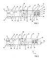
- Figures 1 and 2 depict a first embodiment of a continuous flow structural health monitoring system 10 for monitoring the structural health of a component or structure, such as for example a lap joint (not shown).
- the system 10 comprises a pressure source 2 providing a supply of fluid (typically air) at a regulated pressure difference relative to ambient pressure.
- a fluidic circuit 14 is coupled at one end 16 to the pressure source 12 and is open at an opposite end 18 to ambient pressure via an atmosphere vent 19.
- the pressure source 12 produces a substantially constant and continuous flow of air through the fluidic circuit 14.
- the circuit includes a passage 20 which is constituted at least in part by a first surface portion of the component or structure being monitored.
- a flow measurement system or module 22 continuously monitors for perturbations in the substantially constant flow of fluid through the first passage 20 to provide an indication of structural health of the component or structure.
- a crack 58 develops and propagates from or into the first surface portion which forms part of the first passage 20 and extends to form a fluidic bridge to the ambient atmosphere, there will be an increase in the fluid flow through the circuit 14 and thus through the passage 20.
- This increase of flow will occur irrespective of whether the pressure source 12 is a relative vacuum or a relative positive source, but the direction of flow will be in opposite directions for each.
- changes in the substantially constant air flow through the circuit 14 and/or passage 20 may be indicative of the structural health of the structure or component in question.
- system 10 comprises a first fluidic load in the form of a flow restrictor 24 coupled in the circuit 14 between the passage 20 and the end 18; an additional fluidic load in the form of a flow restrictor 26 connected in the circuit 14 in series between the end 16 of the circuit and the passage 20; and, an additional passage 28 coupled in series between the flow restrictor 24 and the end 18.
- the fluidic circuit 14 also comprises a plurality of tubes or conduits 32 - 42, with tube 32 fluidically connecting the pressure source 12 to the flow restrictor 26, tube 34 fluidically connecting the flow restrictor 26 to the passage 20, tube 36 fluidically connecting the passage 20 to the flow restrictor 24, tube 38 fluidically connecting the flow restrictor 24 to the passage 28, tube 40 connecting the passage 28 to the measurement system/module 22 and a tube 42 fluidically connecting the measurement module 22 to the ambient vent 19.
- a filter 46 is provided between the tube 42 and the vent 19 to prevent the ingress of foreign matter (in the event that the pressure source 12 is a relative negative source, or the source is inactive) which may otherwise block or adversely effect the flow of fluid through the circuit 14.
- the pressure source 12 comprises a pump 13 and a regulator 15 which controls, or provides a stable difference in, fluid pressure of the source 12 referenced to ambient pressure. Thus when there is a change in ambient pressure there will be a corresponding change in the pressure source 12 to maintain the regulated difference.
- Passages 20 and 28 may be formed as part of a sensor 48 that is adhered to the surface of the component or structure being monitored.
- the sensor 48 may be in the form of sensors developed by present applicant and as described in for example US patent nos. US 6,715,365 and US 6,539,776 ; as well as International publication no. WO 2007/115363 .
- the sensor 48 may be in the form of a pad of resilient material in which is formed two separate and spaced apart grooves or channels that, in this embodiment, lie wholly within the footprint or boundary of the sensor 48. The grooves or channels open onto a bottom surface of the sensor 48 which in turn is adhered onto the surface of the component or structure being monitored.
- Connectors 49 allow the conduits 34, 36, 38 and 40 to connect to opposite ends of the respective grooves or channels.
- the grooves or channels when sealed against the surface of the component or structure being monitored form the respective passages 20 and 28.
- fluid flowing through the circuit 14 when it flows through the passages 20 and 28 also flows against respective spaced apart surface portions of the component or structure being monitored.
- the flow restrictors 24 and 26 may be in the form of lengths of small bore tubing having a known resistance to fluid flow. Each of the restrictors 24 and 26 may form part of the measurement module 22 as an integral unit.
- the system 10 also includes a number of pressure sensors 50, 52 and 54,which may also be formed as part of the measurement module 22.
- the sensor 50 taps into a point between the end16 of the pressure source 12 and the restrictor 26 and provides a measure of fluid pressure in the tube 32 which is the same as the pressure of source 12. This pressure is designated as P T .
- the pressure sensor 52 provides a measure of pressure on the side of the flow restrictor 26 opposite the source 12, and is designated as pressure P S .
- the pressure sensor 54 provides a measure of pressure in the portion of the tube 42 vented to the atmosphere, and thus provides atmospheric pressure, is designated as P A .
- the pressure source 12 provides a vacuum that is regulated to be at a stable level referred to ambient pressure. Air flows continuously from the ambient vent 19 through the filter 46, tube 42, tube 40, passage 28, tube 38, flow restrictor 24, tube 36, passage 20, tube 34, flow restrictor 26, relatively negative pressurized tube 32, to the source 12.
- the amount of air flowing is mainly determined by: the flow restrictors 24 and 26 which can have the same value or different values; and, the pressure difference between the tube 32, and the tube 42 (i.e. pressure difference between the pressure source 12 and ambient pressure, i.e.
- C 24 and C 26 are the volumetric conductivity of the flow restrictors 24 and 26 respectively, determined by Poiseuilles' Law. The derivation of this relationship is set out below.
- the pressure P 24 in flow restrictor 24 can be approximated as ( P A + P S )/2
- the pressure P 26 in flow restrictor 26 can be approximated as ( P S + P T )/2
- V ⁇ 24 P A - P S r 24
- V ⁇ 26 P S - P T r 26
- P A + P S ⁇ P A - P S r 24 P S + P T ⁇ P S - P T r 26
- a crack 58 has developed in the surface of the component or structure where the crack 58 provides a fluid flow path to either ambient pressure or the passage 28 which, is vented to ambient pressure via the tubes 40 and 42.
- the crack 58 creates an additional conductivity to air flow between the passage 20 and ambient pressure (either directly or via the passage 28).
- the crack conductance C crack shunts across the flow restrictor 24. This crack changes the fluidic load on the passage 20. Due to the parallel configuration of the crack 58 and the flow restrictor 24, the total resistive load to fluid flow decreases, i.e. the effective conductance to fluid flow increases.
- C 24 and C 26 of the flow restrictors 24, 26 and the measured pressure values of P A , P S and P T the conductivity of C crack can be calculated.
- C crack i.e. the conductance of the crack
- C crack will have a non zero value when no crack is present. This may be considered to be a base noise level.
- the conductance of the crack C crack is determined by the measurement system 22 by measurement of the pressures P T , P S and P A and utilisation of the known conductances of the restrictors 24 and 26.
- An increase in the value C crack from the base noise level indicates the presence of a crack and is manifested by a change in the flow of fluid through the circuit 14 from the constant reference level. The larger the value of the measured crack conductance C crack above the base noise level the larger the crack.
- Sensitivity of the system may be enhanced by several orders of magnitude by provision of a differential system in which two substantially identical fluidic circuits are coupled between the pressure source 12 and the ambient vent 19.
- a differential system in which two substantially identical fluidic circuits are coupled between the pressure source 12 and the ambient vent 19.
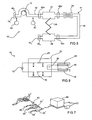
- Such a system is depicted in Figure 3 in which features identical to those depicted and described in relation to Figure 1 utilise the same reference numbers, and features of a second fluidic circuit that perform the same function as those of the first circuit have the same reference number but with the addition of a prime (') symbol.
- the embodiment system 10 depicted in Figure 3 differs from that depicted in Figure 1 by the addition of a duplicate reference fluidic circuit 14'. That is, the system 10 in Figure 3 comprises a fluidic circuit 14 identical to the circuit 14 depicted in Figure 1 but in addition a reference circuit 14' extending from an end 16' in fluidic communication with the pressure source 12 to an opposite end 18' in fluid communication with the ambient vent 19. Starting from the vent 19, the circuit 14' also comprises the following series connected elements: tube 42', measurement module 22', tube 40', passage 28', tube 38', flow restrictor 24', tube 36', passage 20', tube 34', flow restrictors 26', and tube 32' coupled with the pressure source 12.
- a pressure sensor 60 provides a measure of pressure on a side of flow restrictor 26' adjacent to the passage 20', which is designated as P S3 .
- the circuit 14' and in particular its individual components, flow restrictors 24', 26' and passages 20', 28' are formed to have matched fluidic characteristics to the circuit 14 and its corresponding individual components.
- the passage 20' is formed as part of the bulk material of the sensor 48' and does not have a surface that includes a portion of the surface of the component or structure being monitored. Accordingly the passage 20' cannot be penetrated by a crack.
- the absolute pressure P S1 in tube 34 is equal to the pressure P S3 in tube 34'.
- Such a differential measuring configuration provides significantly lower C crack threshold levels than the system depicted in Figures 1 and 2 .
- the system configuration, and in particular the sensor 48' is more complex.
- the system shown in Figure 4 provides a simplified sensor 48'a in which the ambient passages 28 and 28' are cognate into a single ambient passage 28'a.
- C CRACK1 is the mathematical conductance of a crack breaching passage 20 in a theoretically ideal system.
- equation (6) is a mathematical model only of a theoretical crack shunted across the flow restrictor 24'.
- the passage 20' is formed internally of the bulk material of the sensor 48'a it cannot be penetrated by a crack in the surface of the structure being monitored. Nevertheless taking this approach allows a very elegant method of compensating for imperfections in the calculation of C crack1 as well as substantially reducing the effects of transients in fast changing environments because it inherently provides common mode noise rejection.
- c CRACK c 26 ⁇ P S ⁇ 1 2 - P T 2 P A 2 - P S ⁇ 1 2 - P S ⁇ 3 2 - P T 2 P A 2 - P S ⁇ 3 2
- the conductance c CRAcK of crack 58 can be calculated.
- the conductance value of c CRAcK can be expressed in CI, as before.
- FIG. 5 A further embodiment of the system 10 is depicted in Figure 5 where the same reference numbers are used to denote the same or similar features described in previous embodiments.
- both an intake side of pump 13 and passage 28 are vented to ambient pressure via respective vents 19 1 , 19 2 and inline filters 46 1 and 46 2 .
- the fluidic circuit 14 is simplified in this embodiment comprising, in series from the pump 13: tube 32, filter 46a, passage 20, filter 46b, flow restrictor 24, tube 38, filter 46c, and passage 28, which then couples with the filter 46 2 and vent 19 2 .
- Sensors 52 and 54 provide a measure of pressure in tube 32 (i.e. the source pressure) P S and the ambient pressure P A respectively.
- the pump 13 is regulated to maintain a given pressure difference between the pressures P S and P A . This difference is negative for vacuum applications P S ⁇ P A , and positive for over-pressure P S > P A . For the description below, it is assumed that P S is regulated for vacuum (i.e. P S ⁇ P A ).
- the speed of the pump 13 is a measure for the air flow. Setting an appropriate pump speed threshold, the pump speed in a non-crack condition is lower than the threshold. In a crack condition the pump speed is higher than the threshold.
- This pneumatic system uses the regulated speed of pump 13 not only for pumping but also to determine the air flow (and detect a crack 58).
- This pneumatic system is self-contained and requires no external pneumatic source elements.
- measured changes in pump rpm provides an indication of the integrity of the structure.
- the pump speed is regulated to maintain a substantially constant difference between the pressures P T and P A . Any change in speed required to maintain this difference is indicative of the presence of a crack or other fault that is providing a fluid flow path from the passage 20 to ambient pressure.
- the fluidic circuits do not include any valves. This has great benefit when the system is to be used in harsh environment where valve are prone to failure or simply cannot meet environmental requirements, such as at high altitudes where temperatures may easily be in the vicinity of, or, below -55°C. Further benefit arises in that the system is able to also detect a blockage in a fluidic circuit which if not detected would give rise to spurious readings and/or assessments of structural integrity. To the knowledge of Applicant all prior system have required the use of valves to selectively connect and disconnect fluidic circuits to various meters, vents or stops in order to test continuity (ie for the existence of blockages) in the fluidic circuit.
- embodiments of this invention are well suited, but not limited in application, to in flight testing of aircraft and airframes. This then enables detection of cracks well before they may be found in static on ground tests. When in flight aircraft are subject to dynamic loads that may sequentially open and close a crack. But when on the ground, in the absence of dynamic loading a crack may effectively close and thus be more difficult to detect.
- inventions of the system 10 which produce a substantially constant and continuous fluid flow, so that a drop in air flow is indicative of a blockage whereas an increase in air flow is indicative of a crack.
- a blockage of either passage results in a strong negative C crack number.
- a real crack into passage 20 results in strong positive C crack number.
- the purpose of the passage 28/28'a depicted in the embodiments of Figures 1-5 is to provide in effect an ambient pressure source to the first passage 20 should this not be available from outside of the sensor 48.
- the passage 20 When the passage 20 is in fluid communication with ambient pressure via a crack there will then be a change in the mass flow of air though the circuit 14 which will be detected by the system 10.
- the crack will of course be detected by the measured pressures and the calculation of crack conductance as hereinbefore described.
- the path to ambient pressure via the crack can be either to the passage 28/28'a which is part of the sensor 48, or alternatively depending on the direction of propagation of growth of the crack the path maybe to any point outside of the foot print of the sensor 48.
- the sensor 48 can be designed or orientated so that the passage 20 is the first intersected by a crack, which provides a leakage path to ambient pressure. As the crack propagates further it will then intersect the passage 28 which will provide a further leakage path to ambient pressure thereby changing the mass flow though the circuit 14, with the size of the crack being indicated by the calculated conductance.
- the sensor 48 maybe orientated so that the passage 28/28'a is the first passage intersected by a propagating crack. In this orientation the crack must grow a certain length into the ambient passage 28/28'a and then a further distance into the sensing passage 20.
- Figure 6 depicts a further embodiment of the system 10. This embodiment is depicted in simplified form and differs from that shown in Figure 1 by the addition of a further flow restrictor 70 connected in series between the passage 28 and the vent 19. The inclusion of the flow restrictor 70 now allows detection of a crack that intersects the passage 28a and extends to provide a fluid communication path to ambient pressure.
- FIG. 1-6 The measurement systems depicted in Figures 1-6 are shown with a single measurement module 22/22' and single sensor 48/48'a. However multiple measurement modules and sensors maybe used.
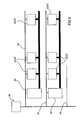
- Figure 7 is a conceptual diagram of one possible airborne structural monitoring system comprising a plurality of measurement modules 22' and sensors 48'a.
- the modules 22' are connected to a common control module 80 by a system bus 82.
- the control module 80 comprises a power supply, data storage and a pressure source for the measurement modules 22' and sensors 48'a.
- An electronic controller inside the control module 80 may conveniently be an aerospace rated off-the shelf single board computer running an appropriately operating system such as Linux, Dos and VxWorks.
- the control module 80 communicates to all the measurement modules 22' and sensors 48'a on a multi-drop bus 82 and is the master control device on the network.
- the protocol may be a standardized protocol such as CAN, PROFIBUS or 1553 inherently supported by the single board computer. Measurement readings are received from the measurement modules 22' processed and then stored. A connector is routed to a convenient location where data maybe downloaded to a storage or other electronic device such a laptop computer or a USB memory stick.
- the pressure source will typically provide a pressure differential of between 10kPa-20kPa above or below ambient pressure and the system maybe able to supply approximately fifty measurement modules 22'.
- Figure 8 illustrates an alternate topology for an airborne structural monitoring system comprising a central module 90, a plurality of separate environmental modules 92, and a plurality of measurement modules 22/22'.
- the central module 90 differs from the control module 80 of Figure 7 in that the central module 90 does not include a pressure source. Rather a pressure source is incorporated in each environmental module 92.
- One or more sensors 48/48'a would be connected to each measurement module, however for the sake of simplicity they are not shown in figure 8 .
- the central module provides a regulated supply voltage and communications for the environmental modules 92 and measurement modules 22/22'visa electrical / communication buses 94; collects, processes and stores data; handles error messages and conditions in the system; and interfaces to the aircraft's structural health monitoring system.
- the environmental modules 92 provide a regulated pressure source for their respective measurement modules 22/22'. Having separate environmental modules allows a subsystem (i.e. a group) of measurement modules 22/22' to be placed in regions or zones which are subjected to different environmental conditions such as in a pressurized cabin, non-pressurize fuselage, non-pressurized wing etc.
- the environmental modules 92 measure ambient temperature, pressure, humidity, acceleration and other environmental parameters/data.
- the measurement modules 22/22' provide pneumatic connectors for single sensors or differential sensors or a chain of sensors, and take measurements of crack data and calculation of the crack conductivity.
Landscapes
- Physics & Mathematics (AREA)
- General Physics & Mathematics (AREA)
- Life Sciences & Earth Sciences (AREA)
- Chemical & Material Sciences (AREA)
- Health & Medical Sciences (AREA)
- Biochemistry (AREA)
- Analytical Chemistry (AREA)
- General Health & Medical Sciences (AREA)
- Immunology (AREA)
- Pathology (AREA)
- Engineering & Computer Science (AREA)
- Aviation & Aerospace Engineering (AREA)
- Food Science & Technology (AREA)
- Medicinal Chemistry (AREA)
- Measuring Volume Flow (AREA)
- Measuring Fluid Pressure (AREA)
Claims (15)
- Système de surveillance de santé structurelle à écoulement continu (10) pour un composant ou une structure, le système comprenant :une source de pression (12) fournissant un fluide d'alimentation avec une différence de pression régulée par rapport à la pression ambiante ;un circuit fluidique (14) qui est couplé à une extrémité à la source de pression (12) et qui est ouvert à une extrémité opposée à la pression ambiante, dans lequel la source de pression (12) produit un écoulement de fluide sensiblement constant et continu à travers le circuit fluidique (14), le circuit fluidique (14) comportant un premier passage (20) constitué en partie par une première partie de surface du composant ou de la structure ; etun système de mesure configuré pour surveiller en continu les perturbations dans l'écoulement de fluide sensiblement constant à travers le premier passage (20) pour fournir une indication de la santé structurelle du composant ou de la structure.
- Système de surveillance de santé structurelle (10) selon la revendication 1, dans lequel le système de surveillance surveille les perturbations dans l'écoulement de fluide en surveillant une variation de conductance d'une charge fluidique sur le premier passage (20).
- Système de surveillance de santé structurelle (10) selon la revendication 2, dans lequel le système de mesure facilite le calcul de la conductance d'une fissure Ccrack dans la première partie de surface qui réalise une communication fluidique entre le premier passage (20) et la pression ambiante, le système de mesure facilitant le calcul de la conductance de la fissure sur la base d'une différence entre une conductance connue de la charge fluidique et une conductance mesurée de la charge fluidique.
- Système de surveillance de santé structurelle (10) selon la revendication 3, dans lequel la charge fluidique comprend un premier réducteur de débit (24) d'une conductance C24 connecté en série dans le circuit fluidique (14) entre le premier passage (20) et l'extrémité opposée du circuit fluidique (14).
- Système de surveillance de santé structurelle (10) selon la revendication 4, dans lequel le système de mesure mesure la pression ambiante et une pression entre le premier passage (20) et la source de pression et utilise ces mesures de pression pour calculer la conductance de la fissure Ccrack.
- Système de surveillance de santé structurelle (10) selon la revendication 5, dans lequel le circuit fluidique (14) comprend un deuxième réducteur de débit (26) d'une conductance C26 connue couplé au premier passage (20) d'un côté opposé au premier réducteur de débit (24).
- Système de surveillance de santé structurelle (10) selon la revendication 6, dans lequel le système de mesure mesure une pression PT entre une source de pression (12) et le deuxième réducteur de débit (26), une pression PS entre la deuxième charge fluidique et le premier passage, et la pression ambiante PA et effectue un calcul de conductance de fissure Ccrack par :

- Système de surveillance de santé structurelle (10) selon l'une quelconque des revendications 1 à 7, comprenant un circuit fluidique de référence qui est couplé à une extrémité à la source de pression (12) et qui est ouvert à une extrémité opposée à la pression ambiante, dans lequel le circuit de référence présente des caractéristiques fluidiques correspondant aux caractéristiques fluidiques du circuit fluidique (14) ; et dans lequel le système de mesure utilise les mesures de pression dans le circuit de référence pour réaliser une annulation de bruit de mode commun pour la surveillance des perturbations dans l'écoulement de fluide à travers le premier passage (20) et pour le calcul de la conductance de la fissure.
- Système de surveillance de santé structurelle (10) selon la revendication 8, dans lequel le circuit fluidique de référence comprend un passage de référence avec des caractéristiques fluidiques correspondant à celles du premier passage, dans lequel le passage de référence est situé à proximité du premier passage et est isolé fluidiquement de la première partie de surface du composant ou de la structure.
- Système de surveillance de santé structurelle (10) selon la revendication 9, dans lequel le système de mesure effectue un calcul de conductance de fissure par :

oùPS1 est une pression mesurée entre le deuxième réducteur de débit (26) et le premier passage (20) ;PT est une pression de source de fluide ;PS3 est une pression fluidique mesurée entre la source de pression (12) et le passage de référence dans le circuit de référence ;PA est la pression ambiante mesurée. - Système de surveillance de santé structurelle (10) selon l'une quelconque des revendications 1 à 3, dans lequel la source de pression (12) comprend une pompe (13) et le système de mesure mesure la vitesse de pompe, dans lequel une variation de la vitesse de pompe mesurée fournit une indication d'une perturbation dans l'écoulement de fluide à travers le premier passage (20).
- Système de surveillance de santé structurelle (10) selon la revendication 11, dans lequel la charge fluidique comprend un premier réducteur de débit (24) d'une conductance C24 connecté en série dans le circuit fluidique entre le premier passage (20) et l'extrémité opposée du circuit fluidique (14) ; et
le système de mesure mesure une pression de source fluidique PT et la pression ambiante PA et calcule la conductance de fissure par :
et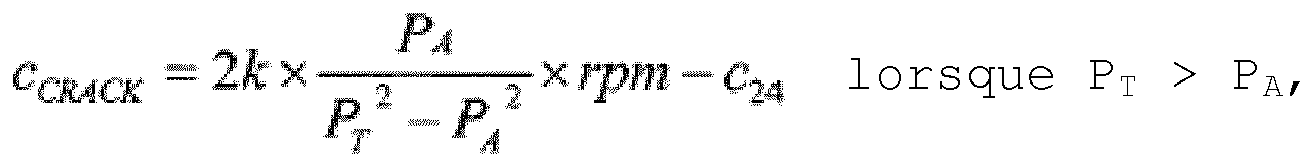
et où rpm est la vitesse mesurée de la pompe (13). - Procédé de surveillance de structure continue comprenant :la prévision d'un circuit fluidique (14) comprenant : un premier passage (20) qui est constitué au moins en partie par une partie d'une surface d'une structure ou d'un composant surveillé ; et un premier réducteur de débit (24) connecté en série d'une conductance C24 connue, le circuit comportant des première et deuxième extrémités, dans lequel la deuxième extrémité du circuit fluidique est mise à la pression ambiante PA ;l'établissement d'un écoulement de fluide sensiblement constant à travers le circuit fluidique (14) ; etle calcul d'une valeur de conductance CCRACK d'une fissure qui réalise un trajet d'écoulement de fluide entre le premier passage (20) et la pression ambiante.
- Procédé selon la revendication 13, dans lequel l'établissement d'un écoulement de fluide sensiblement constant comprend la prévision d'une pompe (13) pour fournir un fluide avec une différence de pression régulée par rapport à la pression ambiante PA, et dans lequel le calcul d'une valeur de conductance de la fissure comprend la mesure de la pression ambiante PA, la mesure de la pression de fluide fournie par la pompe PT, la mesure de la vitesse de pompe rpm et la détermination de la conductance de fissure CCRACK

et
- Procédé selon la revendication 13 ou 14 comprenant :la connexion d'un deuxième réducteur de débit (26) d'une conductance C26 dans le circuit d'un côté opposé du premier passage (20) ; et dans lequel le calcul d'une valeur de conductance d'une fissure comprend la mesure de la pression ambiante PA, la mesure de la pression PS entre le premier réducteur de débit (24) et le premier passage (20), la mesure de la pression PT entre le premier réducteur de débit (24) etla première extrémité du circuit, et le calcul de la conductance de fissure CCRACK par
 où C26 et C24 sont les conductances des premier et deuxième réducteurs de débit respectivement.
Applications Claiming Priority (2)
| Application Number | Priority Date | Filing Date | Title |
|---|---|---|---|
| AU2008900422A AU2008900422A0 (en) | 2008-01-31 | Continuous flow structural health monitoring system and method | |
| PCT/AU2009/000109 WO2009094721A1 (fr) | 2008-01-31 | 2009-01-30 | Système et méthode de vérification en continu de la santé de structures |
Publications (3)
| Publication Number | Publication Date |
|---|---|
| EP2245437A1 EP2245437A1 (fr) | 2010-11-03 |
| EP2245437A4 EP2245437A4 (fr) | 2011-03-23 |
| EP2245437B1 true EP2245437B1 (fr) | 2015-12-23 |
Family
ID=40912176
Family Applications (1)
| Application Number | Title | Priority Date | Filing Date |
|---|---|---|---|
| EP09705336.7A Active EP2245437B1 (fr) | 2008-01-31 | 2009-01-30 | Système et méthode de vérification en continu de la santé de structures |
Country Status (4)
| Country | Link |
|---|---|
| EP (1) | EP2245437B1 (fr) |
| AU (1) | AU2009208394A1 (fr) |
| BR (1) | BRPI0906678B1 (fr) |
| WO (1) | WO2009094721A1 (fr) |
Families Citing this family (2)
| Publication number | Priority date | Publication date | Assignee | Title |
|---|---|---|---|---|
| CA3019429C (fr) * | 2016-04-21 | 2023-12-05 | Henry Abe Kroker | Systeme de detection pour surveiller l'integrite d'une structure |
| CN114660259B (zh) * | 2022-03-17 | 2023-04-14 | 中国民用航空飞行学院 | 一种飞机机翼疲劳裂纹检测设备 |
Family Cites Families (4)
| Publication number | Priority date | Publication date | Assignee | Title |
|---|---|---|---|---|
| US4135386A (en) * | 1977-12-27 | 1979-01-23 | Continental Oil Company | Porous material crack detection |
| AUPR001800A0 (en) * | 2000-09-08 | 2000-10-05 | Structural Monitoring Systems Ltd | Method and apparatus for monitoring the integrity of structures |
| EP2080008A4 (fr) * | 2006-04-04 | 2012-01-04 | Structural Monitoring Sys Ltd | Procédé permettant de détecter les dommages produits par un impact dans une structure |
| PT2100118T (pt) * | 2006-12-05 | 2019-06-17 | Structural Monitoring Systems Ltd | Monitorização da condição de um componente ou estrutura usando fluxo de fluido |
-
2009
- 2009-01-30 WO PCT/AU2009/000109 patent/WO2009094721A1/fr not_active Ceased
- 2009-01-30 BR BRPI0906678-0A patent/BRPI0906678B1/pt active IP Right Grant
- 2009-01-30 AU AU2009208394A patent/AU2009208394A1/en not_active Abandoned
- 2009-01-30 EP EP09705336.7A patent/EP2245437B1/fr active Active
Also Published As
| Publication number | Publication date |
|---|---|
| EP2245437A1 (fr) | 2010-11-03 |
| AU2009208394A1 (en) | 2009-08-06 |
| WO2009094721A1 (fr) | 2009-08-06 |
| EP2245437A4 (fr) | 2011-03-23 |
| BRPI0906678A2 (pt) | 2018-01-23 |
| BRPI0906678B1 (pt) | 2019-05-28 |
Similar Documents
| Publication | Publication Date | Title |
|---|---|---|
| US7251998B2 (en) | Liquid measurement system having a plurality of differential pressure probes | |
| US6609421B2 (en) | Sideslip correction for a multi-function three probe air data system | |
| CN104931007B (zh) | 用于自动估算与航空器的飞行相关的参数的方法和装置 | |
| US6668640B1 (en) | Dual-channel electronic multi-function probes and methods for realizing dissimilar and independent air data outputs | |
| US5511430A (en) | Method and device for detecting that the design loads of an aircraft have been exceeded | |
| US6452542B1 (en) | Integrated flight management system | |
| KR20040097136A (ko) | 유량 측정 방법 및 유량계, 그것에 사용하는 유량 측정부패키지 및 그것을 사용한 유량 측정 유닛, 그리고유량계를 사용한 배관 누출 검사장치 | |
| US10627280B2 (en) | Integrated sensor unit for fuel gauging | |
| EP2245437B1 (fr) | Système et méthode de vérification en continu de la santé de structures | |
| US20170284856A1 (en) | Aircraft weight estimation | |
| US9031796B2 (en) | Continuous flow structural health monitoring system and method | |
| EP3392626B1 (fr) | Procédé de jauge de carburant d'aéronef au moyen de sondes virtuelles | |
| US9244053B2 (en) | Apparatus for monitoring aeration in fluid of hydraulic circuit | |
| US20130311112A1 (en) | Method and apparatus for determining the thrust on a vehicle | |
| US12169138B2 (en) | Measuring system for measuring flow including two coriolis flow meters connected in series in a main conduit | |
| CN112461432A (zh) | 一种实现大气数据测量长期稳定的在线修正方法 | |
| US20060001992A1 (en) | Modular pressure sensor drive connectable to a computer | |
| EP3196619B1 (fr) | Compensation d'erreurs de température passive pour capteurs | |
| EP3446091B1 (fr) | Système de détection pour surveiller l'intégrité d'une structure | |
| EP2100118B1 (fr) | Surveillance de la condition d'un composant ou d'une structure en utilisant un écoulement de fluide | |
| EP4096349A1 (fr) | Surveillance de l'état d'un ensemble de chauffage à résistance à coefficient de température positif | |
| Samy et al. | Unmanned air vehicle air data estimation using a matrix of pressure sensors: a comparison of neural networks and look-up tables | |
| KR102627338B1 (ko) | 동압 및 정압 계통용 비행 계기 점검장치 | |
| Tanielian | MEMS multisensor system for flight testing | |
| US8443654B2 (en) | Device for monitoring the obstruction of at least two filters of a fluid circulation system of an aircraft gas turbine engine |
Legal Events
| Date | Code | Title | Description |
|---|---|---|---|
| PUAI | Public reference made under article 153(3) epc to a published international application that has entered the european phase |
Free format text: ORIGINAL CODE: 0009012 |
|
| 17P | Request for examination filed |
Effective date: 20100830 |
|
| AK | Designated contracting states |
Kind code of ref document: A1 Designated state(s): AT BE BG CH CY CZ DE DK EE ES FI FR GB GR HR HU IE IS IT LI LT LU LV MC MK MT NL NO PL PT RO SE SI SK TR |
|
| AX | Request for extension of the european patent |
Extension state: AL BA RS |
|
| A4 | Supplementary search report drawn up and despatched |
Effective date: 20110221 |
|
| DAX | Request for extension of the european patent (deleted) | ||
| GRAP | Despatch of communication of intention to grant a patent |
Free format text: ORIGINAL CODE: EPIDOSNIGR1 |
|
| INTG | Intention to grant announced |
Effective date: 20150706 |
|
| GRAS | Grant fee paid |
Free format text: ORIGINAL CODE: EPIDOSNIGR3 |
|
| GRAA | (expected) grant |
Free format text: ORIGINAL CODE: 0009210 |
|
| AK | Designated contracting states |
Kind code of ref document: B1 Designated state(s): AT BE BG CH CY CZ DE DK EE ES FI FR GB GR HR HU IE IS IT LI LT LU LV MC MK MT NL NO PL PT RO SE SI SK TR |
|
| REG | Reference to a national code |
Ref country code: GB Ref legal event code: FG4D |
|
| REG | Reference to a national code |
Ref country code: CH Ref legal event code: EP |
|
| REG | Reference to a national code |
Ref country code: IE Ref legal event code: FG4D |
|
| REG | Reference to a national code |
Ref country code: AT Ref legal event code: REF Ref document number: 766756 Country of ref document: AT Kind code of ref document: T Effective date: 20160115 |
|
| REG | Reference to a national code |
Ref country code: DE Ref legal event code: R096 Ref document number: 602009035366 Country of ref document: DE |
|
| REG | Reference to a national code |
Ref country code: FR Ref legal event code: PLFP Year of fee payment: 8 |
|
| REG | Reference to a national code |
Ref country code: NL Ref legal event code: FP |
|
| REG | Reference to a national code |
Ref country code: LT Ref legal event code: MG4D |
|
| PG25 | Lapsed in a contracting state [announced via postgrant information from national office to epo] |
Ref country code: LT Free format text: LAPSE BECAUSE OF FAILURE TO SUBMIT A TRANSLATION OF THE DESCRIPTION OR TO PAY THE FEE WITHIN THE PRESCRIBED TIME-LIMIT Effective date: 20151223 Ref country code: HR Free format text: LAPSE BECAUSE OF FAILURE TO SUBMIT A TRANSLATION OF THE DESCRIPTION OR TO PAY THE FEE WITHIN THE PRESCRIBED TIME-LIMIT Effective date: 20151223 Ref country code: NO Free format text: LAPSE BECAUSE OF FAILURE TO SUBMIT A TRANSLATION OF THE DESCRIPTION OR TO PAY THE FEE WITHIN THE PRESCRIBED TIME-LIMIT Effective date: 20160323 |
|
| REG | Reference to a national code |
Ref country code: AT Ref legal event code: MK05 Ref document number: 766756 Country of ref document: AT Kind code of ref document: T Effective date: 20151223 |
|
| PG25 | Lapsed in a contracting state [announced via postgrant information from national office to epo] |
Ref country code: BE Free format text: LAPSE BECAUSE OF NON-PAYMENT OF DUE FEES Effective date: 20160131 Ref country code: GR Free format text: LAPSE BECAUSE OF FAILURE TO SUBMIT A TRANSLATION OF THE DESCRIPTION OR TO PAY THE FEE WITHIN THE PRESCRIBED TIME-LIMIT Effective date: 20160324 Ref country code: FI Free format text: LAPSE BECAUSE OF FAILURE TO SUBMIT A TRANSLATION OF THE DESCRIPTION OR TO PAY THE FEE WITHIN THE PRESCRIBED TIME-LIMIT Effective date: 20151223 Ref country code: LV Free format text: LAPSE BECAUSE OF FAILURE TO SUBMIT A TRANSLATION OF THE DESCRIPTION OR TO PAY THE FEE WITHIN THE PRESCRIBED TIME-LIMIT Effective date: 20151223 Ref country code: SE Free format text: LAPSE BECAUSE OF FAILURE TO SUBMIT A TRANSLATION OF THE DESCRIPTION OR TO PAY THE FEE WITHIN THE PRESCRIBED TIME-LIMIT Effective date: 20151223 |
|
| PG25 | Lapsed in a contracting state [announced via postgrant information from national office to epo] |
Ref country code: IT Free format text: LAPSE BECAUSE OF FAILURE TO SUBMIT A TRANSLATION OF THE DESCRIPTION OR TO PAY THE FEE WITHIN THE PRESCRIBED TIME-LIMIT Effective date: 20151223 Ref country code: CZ Free format text: LAPSE BECAUSE OF FAILURE TO SUBMIT A TRANSLATION OF THE DESCRIPTION OR TO PAY THE FEE WITHIN THE PRESCRIBED TIME-LIMIT Effective date: 20151223 Ref country code: ES Free format text: LAPSE BECAUSE OF FAILURE TO SUBMIT A TRANSLATION OF THE DESCRIPTION OR TO PAY THE FEE WITHIN THE PRESCRIBED TIME-LIMIT Effective date: 20151223 |
|
| PG25 | Lapsed in a contracting state [announced via postgrant information from national office to epo] |
Ref country code: EE Free format text: LAPSE BECAUSE OF FAILURE TO SUBMIT A TRANSLATION OF THE DESCRIPTION OR TO PAY THE FEE WITHIN THE PRESCRIBED TIME-LIMIT Effective date: 20151223 Ref country code: LU Free format text: LAPSE BECAUSE OF FAILURE TO SUBMIT A TRANSLATION OF THE DESCRIPTION OR TO PAY THE FEE WITHIN THE PRESCRIBED TIME-LIMIT Effective date: 20160130 Ref country code: RO Free format text: LAPSE BECAUSE OF FAILURE TO SUBMIT A TRANSLATION OF THE DESCRIPTION OR TO PAY THE FEE WITHIN THE PRESCRIBED TIME-LIMIT Effective date: 20151223 Ref country code: SK Free format text: LAPSE BECAUSE OF FAILURE TO SUBMIT A TRANSLATION OF THE DESCRIPTION OR TO PAY THE FEE WITHIN THE PRESCRIBED TIME-LIMIT Effective date: 20151223 Ref country code: PL Free format text: LAPSE BECAUSE OF FAILURE TO SUBMIT A TRANSLATION OF THE DESCRIPTION OR TO PAY THE FEE WITHIN THE PRESCRIBED TIME-LIMIT Effective date: 20151223 Ref country code: AT Free format text: LAPSE BECAUSE OF FAILURE TO SUBMIT A TRANSLATION OF THE DESCRIPTION OR TO PAY THE FEE WITHIN THE PRESCRIBED TIME-LIMIT Effective date: 20151223 Ref country code: IS Free format text: LAPSE BECAUSE OF FAILURE TO SUBMIT A TRANSLATION OF THE DESCRIPTION OR TO PAY THE FEE WITHIN THE PRESCRIBED TIME-LIMIT Effective date: 20160423 Ref country code: PT Free format text: LAPSE BECAUSE OF FAILURE TO SUBMIT A TRANSLATION OF THE DESCRIPTION OR TO PAY THE FEE WITHIN THE PRESCRIBED TIME-LIMIT Effective date: 20160426 |
|
| REG | Reference to a national code |
Ref country code: CH Ref legal event code: PL |
|
| REG | Reference to a national code |
Ref country code: DE Ref legal event code: R097 Ref document number: 602009035366 Country of ref document: DE |
|
| PG25 | Lapsed in a contracting state [announced via postgrant information from national office to epo] |
Ref country code: MC Free format text: LAPSE BECAUSE OF FAILURE TO SUBMIT A TRANSLATION OF THE DESCRIPTION OR TO PAY THE FEE WITHIN THE PRESCRIBED TIME-LIMIT Effective date: 20151223 |
|
| PLBE | No opposition filed within time limit |
Free format text: ORIGINAL CODE: 0009261 |
|
| STAA | Information on the status of an ep patent application or granted ep patent |
Free format text: STATUS: NO OPPOSITION FILED WITHIN TIME LIMIT |
|
| PG25 | Lapsed in a contracting state [announced via postgrant information from national office to epo] |
Ref country code: DK Free format text: LAPSE BECAUSE OF FAILURE TO SUBMIT A TRANSLATION OF THE DESCRIPTION OR TO PAY THE FEE WITHIN THE PRESCRIBED TIME-LIMIT Effective date: 20151223 Ref country code: LI Free format text: LAPSE BECAUSE OF NON-PAYMENT OF DUE FEES Effective date: 20160131 Ref country code: CH Free format text: LAPSE BECAUSE OF NON-PAYMENT OF DUE FEES Effective date: 20160131 |
|
| REG | Reference to a national code |
Ref country code: IE Ref legal event code: MM4A |
|
| 26N | No opposition filed |
Effective date: 20160926 |
|
| PG25 | Lapsed in a contracting state [announced via postgrant information from national office to epo] |
Ref country code: BE Free format text: LAPSE BECAUSE OF FAILURE TO SUBMIT A TRANSLATION OF THE DESCRIPTION OR TO PAY THE FEE WITHIN THE PRESCRIBED TIME-LIMIT Effective date: 20151223 |
|
| REG | Reference to a national code |
Ref country code: FR Ref legal event code: PLFP Year of fee payment: 9 |
|
| PG25 | Lapsed in a contracting state [announced via postgrant information from national office to epo] |
Ref country code: IE Free format text: LAPSE BECAUSE OF NON-PAYMENT OF DUE FEES Effective date: 20160130 |
|
| PG25 | Lapsed in a contracting state [announced via postgrant information from national office to epo] |
Ref country code: SI Free format text: LAPSE BECAUSE OF FAILURE TO SUBMIT A TRANSLATION OF THE DESCRIPTION OR TO PAY THE FEE WITHIN THE PRESCRIBED TIME-LIMIT Effective date: 20151223 |
|
| PG25 | Lapsed in a contracting state [announced via postgrant information from national office to epo] |
Ref country code: MT Free format text: LAPSE BECAUSE OF FAILURE TO SUBMIT A TRANSLATION OF THE DESCRIPTION OR TO PAY THE FEE WITHIN THE PRESCRIBED TIME-LIMIT Effective date: 20151223 |
|
| REG | Reference to a national code |
Ref country code: FR Ref legal event code: PLFP Year of fee payment: 10 |
|
| PG25 | Lapsed in a contracting state [announced via postgrant information from national office to epo] |
Ref country code: HU Free format text: LAPSE BECAUSE OF FAILURE TO SUBMIT A TRANSLATION OF THE DESCRIPTION OR TO PAY THE FEE WITHIN THE PRESCRIBED TIME-LIMIT; INVALID AB INITIO Effective date: 20090130 Ref country code: CY Free format text: LAPSE BECAUSE OF FAILURE TO SUBMIT A TRANSLATION OF THE DESCRIPTION OR TO PAY THE FEE WITHIN THE PRESCRIBED TIME-LIMIT Effective date: 20151223 |
|
| PG25 | Lapsed in a contracting state [announced via postgrant information from national office to epo] |
Ref country code: MK Free format text: LAPSE BECAUSE OF FAILURE TO SUBMIT A TRANSLATION OF THE DESCRIPTION OR TO PAY THE FEE WITHIN THE PRESCRIBED TIME-LIMIT Effective date: 20151223 Ref country code: MT Free format text: LAPSE BECAUSE OF FAILURE TO SUBMIT A TRANSLATION OF THE DESCRIPTION OR TO PAY THE FEE WITHIN THE PRESCRIBED TIME-LIMIT Effective date: 20160131 Ref country code: TR Free format text: LAPSE BECAUSE OF FAILURE TO SUBMIT A TRANSLATION OF THE DESCRIPTION OR TO PAY THE FEE WITHIN THE PRESCRIBED TIME-LIMIT Effective date: 20151223 |
|
| PG25 | Lapsed in a contracting state [announced via postgrant information from national office to epo] |
Ref country code: BG Free format text: LAPSE BECAUSE OF FAILURE TO SUBMIT A TRANSLATION OF THE DESCRIPTION OR TO PAY THE FEE WITHIN THE PRESCRIBED TIME-LIMIT Effective date: 20151223 |
|
| PGFP | Annual fee paid to national office [announced via postgrant information from national office to epo] |
Ref country code: NL Payment date: 20250121 Year of fee payment: 17 |
|
| PGFP | Annual fee paid to national office [announced via postgrant information from national office to epo] |
Ref country code: DE Payment date: 20250121 Year of fee payment: 17 |
|
| PGFP | Annual fee paid to national office [announced via postgrant information from national office to epo] |
Ref country code: FR Payment date: 20250127 Year of fee payment: 17 |
|
| PGFP | Annual fee paid to national office [announced via postgrant information from national office to epo] |
Ref country code: GB Payment date: 20250128 Year of fee payment: 17 |