EP2245428B1 - Mesure matérialisée, dispositif de mesure et procédé de mesure pour déterminer une position absolue - Google Patents
Mesure matérialisée, dispositif de mesure et procédé de mesure pour déterminer une position absolue Download PDFInfo
- Publication number
- EP2245428B1 EP2245428B1 EP09713229.4A EP09713229A EP2245428B1 EP 2245428 B1 EP2245428 B1 EP 2245428B1 EP 09713229 A EP09713229 A EP 09713229A EP 2245428 B1 EP2245428 B1 EP 2245428B1
- Authority
- EP
- European Patent Office
- Prior art keywords
- absolute
- markings
- measuring
- track
- sensors
- Prior art date
- Legal status (The legal status is an assumption and is not a legal conclusion. Google has not performed a legal analysis and makes no representation as to the accuracy of the status listed.)
- Not-in-force
Links
Images


Classifications
-
- G—PHYSICS
- G01—MEASURING; TESTING
- G01D—MEASURING NOT SPECIALLY ADAPTED FOR A SPECIFIC VARIABLE; ARRANGEMENTS FOR MEASURING TWO OR MORE VARIABLES NOT COVERED IN A SINGLE OTHER SUBCLASS; TARIFF METERING APPARATUS; MEASURING OR TESTING NOT OTHERWISE PROVIDED FOR
- G01D5/00—Mechanical means for transferring the output of a sensing member; Means for converting the output of a sensing member to another variable where the form or nature of the sensing member does not constrain the means for converting; Transducers not specially adapted for a specific variable
- G01D5/12—Mechanical means for transferring the output of a sensing member; Means for converting the output of a sensing member to another variable where the form or nature of the sensing member does not constrain the means for converting; Transducers not specially adapted for a specific variable using electric or magnetic means
- G01D5/244—Mechanical means for transferring the output of a sensing member; Means for converting the output of a sensing member to another variable where the form or nature of the sensing member does not constrain the means for converting; Transducers not specially adapted for a specific variable using electric or magnetic means influencing characteristics of pulses or pulse trains; generating pulses or pulse trains
- G01D5/245—Mechanical means for transferring the output of a sensing member; Means for converting the output of a sensing member to another variable where the form or nature of the sensing member does not constrain the means for converting; Transducers not specially adapted for a specific variable using electric or magnetic means influencing characteristics of pulses or pulse trains; generating pulses or pulse trains using a variable number of pulses in a train
- G01D5/2451—Incremental encoders
-
- F—MECHANICAL ENGINEERING; LIGHTING; HEATING; WEAPONS; BLASTING
- F16—ENGINEERING ELEMENTS AND UNITS; GENERAL MEASURES FOR PRODUCING AND MAINTAINING EFFECTIVE FUNCTIONING OF MACHINES OR INSTALLATIONS; THERMAL INSULATION IN GENERAL
- F16C—SHAFTS; FLEXIBLE SHAFTS; ELEMENTS OR CRANKSHAFT MECHANISMS; ROTARY BODIES OTHER THAN GEARING ELEMENTS; BEARINGS
- F16C19/00—Bearings with rolling contact, for exclusively rotary movement
- F16C19/22—Bearings with rolling contact, for exclusively rotary movement with bearing rollers essentially of the same size in one or more circular rows, e.g. needle bearings
- F16C19/34—Bearings with rolling contact, for exclusively rotary movement with bearing rollers essentially of the same size in one or more circular rows, e.g. needle bearings for both radial and axial load
- F16C19/38—Bearings with rolling contact, for exclusively rotary movement with bearing rollers essentially of the same size in one or more circular rows, e.g. needle bearings for both radial and axial load with two or more rows of rollers
- F16C19/381—Bearings with rolling contact, for exclusively rotary movement with bearing rollers essentially of the same size in one or more circular rows, e.g. needle bearings for both radial and axial load with two or more rows of rollers with at least one row for radial load in combination with at least one row for axial load
-
- F—MECHANICAL ENGINEERING; LIGHTING; HEATING; WEAPONS; BLASTING
- F16—ENGINEERING ELEMENTS AND UNITS; GENERAL MEASURES FOR PRODUCING AND MAINTAINING EFFECTIVE FUNCTIONING OF MACHINES OR INSTALLATIONS; THERMAL INSULATION IN GENERAL
- F16C—SHAFTS; FLEXIBLE SHAFTS; ELEMENTS OR CRANKSHAFT MECHANISMS; ROTARY BODIES OTHER THAN GEARING ELEMENTS; BEARINGS
- F16C2300/00—Application independent of particular apparatuses
- F16C2300/10—Application independent of particular apparatuses related to size
- F16C2300/14—Large applications, e.g. bearings having an inner diameter exceeding 500 mm
-
- F—MECHANICAL ENGINEERING; LIGHTING; HEATING; WEAPONS; BLASTING
- F16—ENGINEERING ELEMENTS AND UNITS; GENERAL MEASURES FOR PRODUCING AND MAINTAINING EFFECTIVE FUNCTIONING OF MACHINES OR INSTALLATIONS; THERMAL INSULATION IN GENERAL
- F16C—SHAFTS; FLEXIBLE SHAFTS; ELEMENTS OR CRANKSHAFT MECHANISMS; ROTARY BODIES OTHER THAN GEARING ELEMENTS; BEARINGS
- F16C2322/00—Apparatus used in shaping articles
- F16C2322/39—General build up of machine tools, e.g. spindles, slides, actuators
-
- F—MECHANICAL ENGINEERING; LIGHTING; HEATING; WEAPONS; BLASTING
- F16—ENGINEERING ELEMENTS AND UNITS; GENERAL MEASURES FOR PRODUCING AND MAINTAINING EFFECTIVE FUNCTIONING OF MACHINES OR INSTALLATIONS; THERMAL INSULATION IN GENERAL
- F16C—SHAFTS; FLEXIBLE SHAFTS; ELEMENTS OR CRANKSHAFT MECHANISMS; ROTARY BODIES OTHER THAN GEARING ELEMENTS; BEARINGS
- F16C33/00—Parts of bearings; Special methods for making bearings or parts thereof
- F16C33/30—Parts of ball or roller bearings
- F16C33/58—Raceways; Race rings
- F16C33/583—Details of specific parts of races
- F16C33/586—Details of specific parts of races outside the space between the races, e.g. end faces or bore of inner ring
-
- F—MECHANICAL ENGINEERING; LIGHTING; HEATING; WEAPONS; BLASTING
- F16—ENGINEERING ELEMENTS AND UNITS; GENERAL MEASURES FOR PRODUCING AND MAINTAINING EFFECTIVE FUNCTIONING OF MACHINES OR INSTALLATIONS; THERMAL INSULATION IN GENERAL
- F16C—SHAFTS; FLEXIBLE SHAFTS; ELEMENTS OR CRANKSHAFT MECHANISMS; ROTARY BODIES OTHER THAN GEARING ELEMENTS; BEARINGS
- F16C41/00—Other accessories, e.g. devices integrated in the bearing not relating to the bearing function as such
- F16C41/007—Encoders, e.g. parts with a plurality of alternating magnetic poles
Definitions
- the invention relates to a material measure for a position-measuring device, comprising at least one measuring track with incremental markings and at least one measuring track with absolute markings.
- the invention further relates to a position measuring device comprising a material measure according to the invention.
- the invention further relates to a method for determining a measuring position of a first body with respect to a second body by means of a position-measuring device according to the invention and a method for calibrating a position-measuring device according to the invention such mecanicver stresses, position measuring devices or Position measuring methods which permit a determination of the absolute position of a body can be used, for example, in surveying equipment or, with appropriate feedback, also in speed and / or position control loops.
- Incremental measuring systems for this purpose are based either on the incremental or the absolute measuring principle.
- Incremental measuring systems have a material measure with a multiplicity of markings arranged at the same distance or the same angle along a measuring path, similar to a bar code (incremental markings). If a body, comprising a corresponding scanning device, is displaced along the measuring path relative to the measuring standard, the scanning device can count the number of incremental markings traveled over. Due to the known distance between two incremental markings, the distance covered can be determined.
- incremental measuring devices have a simple structure and are therefore widely used. The disadvantage, however, is that they do not allow any absolute position determination of a body in a direct way.
- absolute measuring systems practically enable an absolute position determination directly after switching on.
- a large number of positional information is stored along the measuring path on the material measure (absolute markings).
- the absolute marks represent a binary coding of the position information, with increasing the number of bits, the resolution of the measuring system increases.
- the scanning device has a sufficient number of sensor elements in order to read out all the bits of an absolute marking in one step, so that after switching on no or at most a minimum relative movement is necessary in order to read out the absolute position.
- a measuring device whose measuring standard comprises a plurality of code elements, wherein a plurality of code elements lying one behind the other in the measuring direction represent an absolute position information.
- each code element consists of two successive in the measuring direction sections, which have mutually complementary properties.
- the binary information of a code element is obtained by a comparison of the sampling signals of both partial regions.
- the measuring system of WO 03/060431 A1 is based on an optical principle, ie the binary information of the code elements is encoded, for example, by transparent and non-transparent material properties.
- a position measuring system whose measuring graduation comprises incremental markings in the form of periodically arranged recesses and absolute markings arranged between the recesses, the absolute markings being formed, in particular, by magnetic markings.
- the incremental markings are inductive and the absolute marks are not read inductively.
- a disadvantage of measuring systems based on optical scanning principles is the fact that they are susceptible to soiling. Accordingly expensive precautions for shielding eg against lubricants, are therefore necessary.
- Measuring systems in which the absolute markings are formed by magnetic markings have the disadvantage that the irregularly overlapping magnetic fields make the reading difficult or reduce the measuring accuracy.
- the invention has for its object to provide a material measure for a measuring system that is simple and inexpensive to manufacture, allows an absolute position determination and overcomes the aforementioned disadvantages.
- a further object of the invention is to provide a corresponding measuring system and method.
- the invention is based on the finding that the combination of incremental markings consisting of magnetically active elements, ie elements that generate magnetic fields, and absolute marks consisting of magnetically passive elements, ie elements that do not generate magnetic fields themselves, an optimal ratio of design effort, manufacturing costs and costs on the one hand, and measuring accuracy on the other hand can be achieved. In this case, it can even be accepted that different production methods for the measuring track with incremental markings and for the measuring track with absolute markings are necessary, a fact that, from an economic point of view, would have to be avoided on its own. By the incremental markings are formed by magnetically active elements, a very high measurement accuracy can be achieved. It also makes sense to resort to existing incremental measuring systems.
- the formation of the measuring track with absolute markings is carried out according to the invention in a very simple manner, in that the required information is represented by magnetically passive elements.
- the coding of the measuring track with absolute marks easily be adapted to different requirements, such as a certain required resolution.
- the required accuracy of the measuring system is to be achieved by the incremental track, ie the design of the incremental markings and / or the configuration of the sensors for scanning the incremental markings, while the absolute track should only have the information for absolute position determination.
- the material measure according to the invention can be used both in linear measuring systems and in rotary measuring systems.
- the absolute markings are used, e.g. Values between zero and the length of the material measure shown.
- the absolute marks e.g. Values between zero and 360 degrees are shown.
- the graduation of the measuring track with incremental markings and the graduation of the measuring track with absolute markings are in an integer ratio.
- the magnetically active elements are permanent magnets.
- the incremental graduation is embodied by regularly split pairs of poles and can be materially, positively and / or non-positively connected to the machine element that is to carry the material measure.
- the ring carrying the material measure can be made of a ferromagnetic material, for example iron or cobalt, and the incremental graduation subsequently introduced. It is also possible to use a plastic-bonded magnetic powder.
- the magnetically passive elements are formed by a highly permeable material.
- the magnetically passive elements are formed using magnetically conductive and magnetically non-conductive regions.
- the magnetically conductive and the magnetically non-conductive regions alternate along the measuring track. By suitable measuring methods, these areas can be identified and thus the absolute track can be scanned.
- a scanning device with means for generating a magnetic field and sensors for measuring the magnetic flux, such as magnetoresistive sensors, can be provided. In this case, the magnetic flux through the magnetoresistive sensor, when this is positioned over locations with magnetically conductive regions of the absolute track, high and the electrical resistance of the magnetoresistive sensor is changed accordingly.
- the magnetic flux is poorly conducted by non-magnetic regions of the absolute track, so that a larger stray magnetic field is formed and the measured magnetic flux through the magnetoresistive sensor is lower.
- the decisive factor here is not that the magnetically non-conductive regions completely suppress the magnetic flux, but that these regions in comparison to the magnetically conductive regions have a much larger magnetic resistance (reluctance).
- the absolute track should be made of a highly permeable material, in particular of ferromagnetic material. Steels such as 16MnCr5, spring steel, 100Cr6 bearing steel, martensitic stainless steel, but not austenitic stainless steel are particularly suitable for this purpose.
- the magnetically non-conductive regions can be formed in particular by depressions, gaps or holes. Accordingly, the magnetically conductive regions represent, for example, elevations, webs or protrusions. Thus, an absolute track with a structure similar to a perforated strip as used as a data carrier for computer systems is created.
- the magnetically non-conductive regions can be used, for example. be embossed, stamped, lasered or etched.
- the extent of the pits, gaps or holes along the measurement path can be e.g. in a range of 10 microns to 5000 microns, preferably in a range of 200 microns to 1000 microns, more preferably e.g. 500 or 250 microns.
- the pits, gaps or holes may be of any shape, e.g. rectangular, square, circular or elliptical.
- the at least one measuring track with absolute markings is assigned a reference absolute track that runs parallel to the measuring track with absolute markings and magnetically conductive and magnetically non-conductive areas are arranged along the measuring track with absolute markings and along the reference absolute track and the areas of the reference absolute track are complementary
- the reference absolute track serves to increase the reliability of the measurement by measuring one or a part of an absolute mark of the measuring track scanned by the sensors with absolute markings with the corresponding part of an absolute mark scanned by the sensors the reference absolute track can be compared.
- An evaluation facility can take appropriate measures in the event of a deviation from the expected result.
- an absolute position information is encoded in an absolute marking.
- an absolute marking for each absolute position to be identified is its own position information necessary.
- the coding of this position information typically takes place in the form of the binary code.
- sensors each scan a specific area of the absolute track, the absolute position being coded by the binary values stored in this area, ie zeros or ones.
- a simple method is the representation of the binary values by depressions or projections, for example, by a depression corresponds to a zero and a projection corresponds to a one.
- each absolute marking that is, each depression or projection, represents at least one bit.
- a first absolute marking which is twice as long as a second absolute marking, also represents twice as many bits.
- the information for absolute position determination is generally encoded using the geometric shape, in particular the length, width or depth, and / or the position of the magnetically conductive and magnetically non-conductive regions.
- the coding of the absolute position by the absolute markings can be effected by arrangements with consecutive bits along the measuring path (longitudinal coding) as well as arrangements with bits arranged parallel along the measuring path in at least two absolute tracks (transverse coding) or by combinations of these. Even if the coding by means of the binary code represents a very simple possibility, eg a ternary code could also be used, the absolute markings can be represented by differently pronounced depressions.
- the requirements for the scanning device would be greater, but the resolution to be achieved per measuring track with absolute markings could be increased.
- the absolute position can be represented, for example, in dual code or Gray code.
- the coding is preferably carried out in such a way that a new absolute position already results when the scanning device is moved by one bit.
- an information for relative position determination is encoded in an incremental marking.
- the distance or the length of two successive incremental markings determines a specific relative position.
- the measuring track with absolute markings and the measuring track with incremental markings run parallel to one another or cover each other completely.
- Parallel measuring tracks are conceivable both for linear measuring devices and for rotary measuring devices.
- the two measuring tracks generally run in a circular manner next to one another in such a way that both measuring tracks have the same radius, but are offset along the common axis of rotation.
- measuring tracks with different radii are also possible with rotary measuring devices. Overlapping measuring tracks represent a space-saving design.
- the position measuring device comprises a material measure according to the invention and a relatively movable scanning device with sensors for scanning the incremental markings and / or the absolute markings.
- the sensors of the scanning device can be accommodated on a single measuring head, but it can also be used several measuring heads, which are then arranged either directly next to each other or along the measuring section offset.
- the sensors for scanning the incremental markings are formed by sensors for measuring the magnetic flux. Each incremental marker is inserted through shown magnetically active element that generates a corresponding magnetic field. The transitions between two adjacent magnetic fields can be determined by measuring the magnetic flux. By interpolating between two measuring points, ie two transitions, the finally available resolution of the measuring track can be further increased with incremental markings.
- the sensors for scanning the absolute markings are formed by sensors for measuring the magnetic flux, the magnetic induction and / or electromagnetic radiation. The choice of sensors for measuring the magnetic flux is to be preferred for reasons of economy, since the scanning device may have identical sensors, whereby, for example, their control and the evaluation is simplified.
- the sensor elements are preferably smaller than the depressions, gaps or holes. They reproduce the respective track signals as analog and / or digital signals in the usual form. Electronic processing reproduces the signals using common interfaces such as 1 Vpp, En-Dat2.2, SSI, Hyperface, Drive-Click and so on.
- the sensors for measuring the magnetic flux are formed by Hall sensors or magnetoresistive sensors.
- Magnetoresistive sensors based on the AMR effect (Anisotropic Magneto Resistive), are to be preferred in particular at low field strengths.
- GMR sensors Gaant Magneto Resistive
- At least one sensor is located on a part of a housing of the scanning device, in particular on a circuit carrier.
- the sensor can in particular be connected to the circuit carrier in a form-fitting, cohesive or force-locking manner.
- the position measuring device is used in a linear guide comprising a stationary machine element, wherein the material measure is located in particular on the stationary machine element.
- the position measuring device is used in a bearing point of a movable machine part comprising a bearing, wherein the material measure is in particular on the movable machine element.
- the dimensional standard can be used for this purpose, e.g. are located on the cylinder surface of the rotating machine element.
- the measurement accuracy resulting from the incremental markers and the incremental track sensing sensors is greater than the measurement accuracy resulting from the absolute markers and the absolute track sensing sensors.
- the higher measurement accuracy can be achieved by the type of embodiment of the incremental markers and / or by the choice of the type of sensors for scanning the incremental track.
- the advantage here is that the accuracy of the position measuring device can be increased overall by the higher accuracy of the incremental track by incremental markers are assigned to the absolute marks. Due to the periodic and thus simpler structure of the incremental track, this can be relatively easily and inexpensively realize a higher resolution.
- the measuring device must be able to scan sufficient information to determine the absolute position in one step, i. without further (relative) procedure of the measuring device to be able to determine.
- a bit coding of the position information a correspondingly large number of sensors are present in accordance with the number of coded bits. It is not necessary to scan an absolute mark completely, but rather a coherent area of two adjacent absolute markings can be scanned. For a 15-bit coding, therefore, 15 sensors alone are required for the acquisition of the absolute markings.
- the sensors are arranged in alignment along the measuring path; in a transverse coding, the sensors are arranged transversely to the measuring section; in a combination of longitudinal and transverse coding, the sensors are arranged in a corresponding array. If there is a reference absolute track, additional sensors are required.
- the method according to the invention further comprises the step of scanning at least one relative mark by the sensors for scanning the relative marks, wherein the determination of the absolute position based on the at least one scanned absolute mark and the at least one scanned relative mark he follows.
- the determination of the measurement position can be performed by means of synchronization data representing an association between absolute marks and incremental marks. In the process, the actual absolute position is still obtained from the absolute track by scanning the corresponding absolute marking.
- the accuracy and / or the resolution can now be increased by including the sampled incremental marking and corresponding synchronization data in the determination of the absolute position.
- the measuring track with incremental markings is used as an additional scale next to the measurement track with absolute markings, this additional scale having a higher resolution and / or accuracy.
- the higher resolution can be achieved by interpolating between two adjacent incremental markers; a method made possible by the magnetically active elements.
- the magnetically active elements allow a higher measurement accuracy compared to the magnetically passive elements of the measuring track with absolute marks.
- the synchronization data represent the possible offset between the position of the absolute markings and relative markings, which can result if the respective measuring tracks have, for example, an equal pitch but were aligned inaccurately with one another when mounting or mounting on the corresponding body.
- the known calibration position can be determined by measurement by means of a further measuring device. It is also possible that the known calibration position is based on a unique reference position, e.g. the end of a linear measuring section, optionally with a corresponding relative displacement thereto, is determined. After the at least one absolute marking and the at least one relative marking have been scanned, the synchronization data, in particular the offset between the position of the absolute markings and relative markings, can be determined and stored.
- the method steps for calibrating a position-measuring device are carried out at at least two different calibration positions.
- an offset between the position of the absolute markings and relative markings changing along the measuring path can be taken into account.
- the method steps for calibrating a position-measuring device are performed on each absolute marking as a calibration position.
- the accuracy and / or resolution can be further increased.
- For each absolute marking a corresponding offset is deposited.
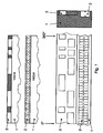
- Fig. 1 shows a schematic representation of an embodiment of a material measure according to the invention. This can be used both for absolute angle coding and for absolute length coding.
- the measuring graduation is applied to a cylinder jacket surface of a disk or of a rotating wave washer of a bearing.
- An incremental division 2 is designed as a regularly split pole pairs, which is incorporated directly on the cylinder surface or in a circumferential groove of the disc cohesively or positively.
- the disc 1 is made, for example, from the bearing steel 100Cr6 or a comparable steel.
- an absolute coding 3 is arranged, which can be wrapped in the form of an endless belt around the disc and is connected in a material-locking, positive or non-positive fit by means of a press or transition fit with the disc.
- the absolute coding 3 has depressions, gaps or holes which can be embossed, stamped, lasered or etched, for example. This results in a random or quasi-random binary division along the measuring path or any other known coding.
- the embodiment according to Fig. 1 shows a longitudinal coding, wherein the single measuring track is associated with absolute marks a Referenzabsolutspur whose areas each have a complementary value.
- the sensors provide analog signals, these mostly by means of a differential amplifier be obtained and measure the voltage potentials of the current-carrying magnetoresistive sensors. By forming the difference between these two analog voltage signals, a zero-point-symmetrical voltage signal is generated, so that temperature drifts, possibly coupled interference signals and offset voltages are compensated, which contributes significantly to an interference-free and highly accurate evaluation and design of the absolute coding.
- a comparator or Schmitt trigger the analog voltage signal is converted in a known manner into digital signals.
- Fig. 2 shows a schematic representation of an embodiment of a position-measuring device according to the invention.
- the material measure corresponds to the material measure according to Fig. 1 , so that reference is made to the corresponding description.
- the scanner 4 includes sensors for non-contact and magnetic detection of both the incremental marks and the absolute marks. The scanning device 4 and the material measure can thereby move along the measuring path relative to each other.
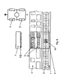
- Fig. 3 shows a schematic representation of a scanning device of a position measuring device according to the invention according to a first embodiment.
- the two magnetoresistive sensors of a sensor pair 5 and 5 are arranged on pole pieces 7 made of ferromagnetic steel by means of insulating plates, such as ceramic, plastic or mica, wherein the pole pieces 7 are designed symmetrically and taken together form the shape of an E.
- the magnetic circuit is magnetically excited by means of permanent magnets 8.
- the two magnets can be opposite directions, as drawn, but also poled in the same direction.
- the pole pieces and the magnets 8 form a magnetic circuit, wherein the height of the magnetic flux density is mutually inversely modulated in both circles by the less-dimensionally-sized recesses or holes in the band inverse to each other.
- the corresponding amplifier and converter electronics, such as Fig. 1 is also housed within a plastic (polyamide fiberglass) or light metal injection molded (aluminum) housing 4 in the form of PCB or hybrid circuits 14.
- the incremental coding 2 formed by magnetically active elements is arranged on the wave disk 1, which is scanned in a known manner by means of a further magnetoresistive sensor 10 or sensor array.
- the associated is also an amplifier and converter electronics 13, which amplifies the signals, processed and fixed in diamagnetic metal (brass, nickel silver, aluminum, etc.), which can also serve as a lid or housing closure.
- diamagnetic metal brass, nickel silver, aluminum, etc.
- PUR and epoxy resin may be that have sufficient elasticity in the cured state and their thermal expansion coefficient can be matched to the mechanical voltage-sensitive electronic components.
- an electrical connection element may be a multi-core, shielded cable line 16, as drawn, but also a connector.
- the magnetoresistive sensors 10 are located on a circuit carrier 11, which also serves as part of the housing of the scanning device.
- Fig. 4 shows a schematic representation of a scanning device of a position measuring device according to the invention according to a second embodiment. This was done without the pole pieces and the magnetic lenses. This results in a component and space-saving design, which can also be manufactured at lower manufacturing costs, as the scanning device according to Fig. 3 ,
- the circuit carrier 11, on which the sensors 5, 5 and 10 are arranged, at the same time represents the outer side of the scanning device facing the material measure.
- Fig. 5 shows a schematic sectional view of the embodiment according to Fig. 2 , Shown is the interaction of the magnetoresistive sensors 5 and 5 and the sensor array, which consists of a plurality of magnetoresistive sensors, with the incremental angle coding 2 and the absolute angle coding 3.
- the pole pitch of the incremental coding 10 may be equal to the absolute coding 5 and 5 , but also an integer multiple thereof, eg factor 2, 3, 4, etc. or an integer fraction of it, eg 1/2, 1/3, 1/4 etc.
- the sensors of a pair 5 and 5 come here alternately congruent with a gap in the absolute angle coding or on metal, from which the differential scanning described above can be realized, which leads to a secure query.
- the sensor pairs can be interconnected in the form of a half-resistor or full-bridge.
- Fig. 6 shows a schematic representation of a measuring track according to the invention with absolute marks. Shown is the mechanical structure of the endless belt 3, on which the magnetically non-conductive regions in the form of recesses or holes is introduced. This design is particularly preferred for angular pitches, wherein the material measure drawn on the cylinder surface of the rotating machine or bearing part is.
- This endless belt is made of a sheet metal, which is then welded at the joint 16 (laser or resistance welding). Before welding, the hole width is determined, measured and monitored.
- Fig. 7 shows a schematic representation of a position measuring device according to the invention integrated in a rotary table.
- the rotary table can be provided, for example, for a machine tool application.
- the scanning device in this case comprises a first scanning head 20 of the measuring system, which includes the sensors for querying the incremental angular pitch and the absolute angle coding, which carries the rotary table bearing with the rotatably mounted wave washer 1, the incremental material measure 2 and the absolute angle coding 3.
- the additional scanning head 19 of the scanning device includes only a sensor for querying the incremental angle division.
- the rotary table 16 is guided in this case by means of an axial / radial cylindrical roller bearing whose component is the wave washer 1.
- the rotary table is driven by means of a torque motor 17 whose rotor (secondary part) is connected to the rotary table 16 directly and mechanically rigid.
- the stator of the torque motor 17 is bolted to the base frame 18. This has the advantage that not only the torque motor is mechanically stiff coupled with the rotating rotary table, but also the measuring system, so that highly dynamic and high-precision positioning tasks can be realized. Other applications than these, such as in swivel bridges or milling heads of machine tools, are feasible in this way. In addition, this application can be transferred to other types of bearings, such as cylindrical rollers, multi-row angular contact ball, tapered roller, cross roller bearings, slewing rings or linear guides.
- Fig. 8 shows a schematic arrangement of two scanning devices according to the embodiment according to Fig. 7 , Shown is the interconnection of the two scanning heads 19 and 20.
- the incremental output signals of the scanning head 19 are transmitted in the scanning head 20, there with the incremental Signals of the scanning head 20 interconnected, such as added or subtracted from each other.
- possible occurring center displacements of the wave washer can be compensated, the incremental angular resolution doubled and the amplitude of the common output signals can also be doubled.
- these are evaluated in combination with the absolute angle coding in the scanning head 20 and output as an absolute value in analog or digital form.
Landscapes
- Physics & Mathematics (AREA)
- General Physics & Mathematics (AREA)
- Transmission And Conversion Of Sensor Element Output (AREA)
Claims (25)
- Ensemble de mesure pour dispositif de mesure de position, comprenant au moins une piste de mesure dotée de repères incrémentiels et au moins une piste de mesure dotée de repères absolus,
caractérisé en ce que
les repères incrémentiels sont formés par des éléments magnétiques actifs et les repères absolus par des éléments magnétiques passifs. - Ensemble de mesure selon la revendication 1, caractérisé en ce que les éléments magnétiques actifs sont des aimants permanents.
- Ensemble de mesure selon les revendications 1 ou 2, caractérisé en ce que les éléments magnétiques passifs sont formés d'un matériau à haute perméabilité.
- Ensemble de mesure selon l'une des revendications 1 à 3, caractérisé en ce que les éléments magnétiques passifs sont formés en recourant à des parties magnétiquement conductrices et à des parties magnétiquement non conductrices.
- Ensemble de mesure selon la revendication 4, caractérisé en ce que les parties magnétiquement conductrices et les parties magnétiquement non conductrices sont alternées le long de la piste de mesure.
- Ensemble de mesure selon l'une des revendications 4 à 5, caractérisé en ce que les parties magnétiquement non conductrices sont formées par des creux, des interstices ou des trous.
- Ensemble de mesure selon l'une des revendications 4 à 6, caractérisé en ce qu'une piste absolue de référence est associée à la ou aux pistes de mesure dotées de repères absolus et s'étend parallèlement à la piste de mesure dotée de repères absolus, des parties magnétiquement conductrices et des parties magnétiquement non conductrices étant disposées le long de la piste de mesure dotée de repères absolus et le long de la piste de référence absolue et les parties de la piste de référence absolue étant configurées de manière complémentaire aux parties de la piste de mesure dotée de repères absolus.
- Ensemble de mesure selon l'une des revendications 1 à 7, caractérisé en ce qu'une information concernant la détermination absolue de position est codée dans un repère absolu.
- Ensemble de mesure selon les revendications 4 et 8, caractérisé en ce que l'information concernant la détermination absolue de position est codée en recourant à la forme géométrique, en particulier à la longueur, la largeur ou la profondeur et/ou à la position des parties magnétiquement conductrices et des parties magnétiquement non conductrices.
- Ensemble de mesure selon l'une des revendications 1 à 9, caractérisé en ce qu'une information concernant la détermination relative de position est codée dans un repère incrémentiel.
- Ensemble de mesure selon l'une des revendications 1 à 10, caractérisé en ce que la piste de mesure dotée de repères absolus et la piste de mesure dotée de repères incrémentiels s'étendent parallèlement l'une à l'autre ou se recouvrent complètement.
- Dispositif de mesure de position comprenant un ensemble de mesure selon l'une des revendications 1 à 11 ainsi qu'un dispositif de palpage mobile par rapport à ce dernier et doté de capteurs qui palpent les repères incrémentiels et/ou les repères absolus.
- Dispositif de mesure de position la revendication 12, caractérisé en ce que les capteurs de palpage des repères incrémentiels sont formés par des capteurs de mesure du flux magnétique.
- Dispositif de mesure de position selon les revendications 12 ou 13, caractérisé en ce que les capteurs de palpage des repères absolus sont formés par des capteurs de mesure du flux magnétique, de l'induction magnétique et/ou d'un rayonnement électromagnétique.
- Dispositif de mesure de position selon les revendications 13 ou 14, caractérisé en ce que les capteurs de mesure de flux magnétique sont formés par des capteurs Hall ou des capteurs magnétorésistifs.
- Dispositif de mesure de position selon l'une des revendications 12 à 15, caractérisé en ce qu'au moins un capteur est situé sur une partie d'un boîtier du dispositif de palpage et en particulier sur un support de circuit.
- Dispositif de mesure de position selon l'une des revendications 12 à 16, caractérisé en ce que le dispositif de mesure de position est utilisé dans un guide linéaire qui comprend un élément de machine immobile et en particulier en ce que l'ensemble de mesure est situé sur l'élément immobile de machine.
- Dispositif de mesure de position selon l'une des revendications 12 à 16, caractérisé en ce que le dispositif de mesure de position est utilisé en un emplacement de montage d'une partie mobile de machine comprenant un palier, et en particulier en ce que l'ensemble de mesure est situé sur l'élément mobile de machine.
- Dispositif de mesure de position selon l'une des revendications 12 à 18, caractérisé en ce que la précision de mesure résultant des repères incrémentiels et les capteurs de palpage de la piste incrémentielle est supérieure à la précision de mesure qui résulte des repères absolus et des capteurs de palpage de la piste absolue.
- Procédé de détermination d'une position de mesure de un premier corps par rapport à un deuxième corps au moyen d'un dispositif de mesure de position selon l'une des revendications 12 à 19, les corps pouvant se déplacer l'un par rapport à l'autre, l'ensemble de mesure étant disposé sur un corps et le dispositif de palpage étant disposé sur un autre corps, le procédé comportant les étapes qui consistent à :placer le premier et/ou le deuxième corps dans la position de mesure à déterminer,palper au moins un repère absolu par les capteurs de palpage des repères absolus etdéterminer la position de mesure à l'aide du ou des repères absolus palpés.
- Procédé de détermination d'une mesure selon la revendication 20, comprenant en outre l'étape qui consiste à palper au moins un repère relatif par les capteurs de palpage des repères relatifs, la détermination de la position absolue s'effectuant à l'aide du ou des repères absolus palpés et du ou des repères relatifs palpés.
- Procédé de détermination d'une mesure selon la revendication 21, caractérisé en ce que la détermination de la position de mesure s'effectue au moyen de données de synchronisation qui constituent une association entre des repères absolus et des repères incrémentiels.
- Procédé d'étalonnage d'un dispositif de mesure de position selon l'une des revendications 12 à 19, comprenant les étapes qui consistent à
placer le dispositif de palpage et/ou l'ensemble de mesure en une position d'étalonnage connue,
palper au moins un repère absolu,
palper au moins un repère relatif et
étalonner le dispositif en conservant en mémoire des données de synchronisation qui constituent une association entre des repères absolus et des repères incrémentiels. - Procédé d'étalonnage d'un dispositif de mesure de position selon la revendication 23, dont les étapes sont exécutées en au moins deux positions d'étalonnage différentes.
- Procédé d'étalonnage d'un dispositif de mesure de position selon la revendication 24, dont les étapes sont exécutées sur chaque repère absolu utilisé comme position d'étalonnage.
Applications Claiming Priority (2)
| Application Number | Priority Date | Filing Date | Title |
|---|---|---|---|
| DE102008010095A DE102008010095A1 (de) | 2008-02-20 | 2008-02-20 | Maßverkörperung, Messeinrichtung und Messverfahren zur Absolutpositionsbestimmung |
| PCT/DE2009/000181 WO2009103263A2 (fr) | 2008-02-20 | 2009-02-10 | Mesure matérialisée, dispositif de mesure et procédé de mesure pour déterminer une position absolue |
Publications (2)
| Publication Number | Publication Date |
|---|---|
| EP2245428A2 EP2245428A2 (fr) | 2010-11-03 |
| EP2245428B1 true EP2245428B1 (fr) | 2015-04-08 |
Family
ID=40896551
Family Applications (1)
| Application Number | Title | Priority Date | Filing Date |
|---|---|---|---|
| EP09713229.4A Not-in-force EP2245428B1 (fr) | 2008-02-20 | 2009-02-10 | Mesure matérialisée, dispositif de mesure et procédé de mesure pour déterminer une position absolue |
Country Status (3)
| Country | Link |
|---|---|
| EP (1) | EP2245428B1 (fr) |
| DE (1) | DE102008010095A1 (fr) |
| WO (1) | WO2009103263A2 (fr) |
Families Citing this family (4)
| Publication number | Priority date | Publication date | Assignee | Title |
|---|---|---|---|---|
| DE102010010501A1 (de) | 2010-03-06 | 2011-09-08 | Ina - Drives & Mechatronics Gmbh & Co. Ohg | Verfahren zur Aufbereitung eines periodischen Messsignals und Messsignalverarbeitungseinheit hierfür |
| DE102012004901A1 (de) * | 2012-03-09 | 2013-09-12 | Carl Zeiss Microscopy Gmbh | Einrichtung zur Positionierung optischer Komponenten an einem Mikroskop |
| DE102017204879A1 (de) * | 2017-03-23 | 2018-09-27 | Robert Bosch Gmbh | Linearwälzlager mit magnetoresistivem Positionsmesssystem |
| CN112810666B (zh) * | 2019-11-15 | 2023-02-10 | 比亚迪股份有限公司 | 列车定位测速方法、设备、系统、计算机设备及存储介质 |
Family Cites Families (5)
| Publication number | Priority date | Publication date | Assignee | Title |
|---|---|---|---|---|
| DE4037545C2 (de) * | 1990-11-26 | 1994-03-17 | Heidenhain Gmbh Dr Johannes | Meßeinrichtung |
| US7013575B2 (en) | 2002-01-17 | 2006-03-21 | Dr. Johannes Heidenhain Gmbh | Position measuring device |
| DE102005031333A1 (de) * | 2005-07-05 | 2007-01-11 | Zf Friedrichshafen Ag | Positionsdetektion an einer Stange |
| DE102005047009A1 (de) | 2005-09-30 | 2007-04-05 | Bosch Rexroth Mechatronics Gmbh | Absolutes Positionsmesssystem |
| GB0523273D0 (en) * | 2005-11-16 | 2005-12-21 | Renishaw Plc | Scale and readhead apparatus and method |
-
2008
- 2008-02-20 DE DE102008010095A patent/DE102008010095A1/de not_active Withdrawn
-
2009
- 2009-02-10 EP EP09713229.4A patent/EP2245428B1/fr not_active Not-in-force
- 2009-02-10 WO PCT/DE2009/000181 patent/WO2009103263A2/fr active Application Filing
Also Published As
| Publication number | Publication date |
|---|---|
| WO2009103263A2 (fr) | 2009-08-27 |
| DE102008010095A1 (de) | 2009-08-27 |
| EP2245428A2 (fr) | 2010-11-03 |
| WO2009103263A3 (fr) | 2009-10-29 |
Similar Documents
| Publication | Publication Date | Title |
|---|---|---|
| EP2182330B1 (fr) | Système de mesure de position/trajectoire doté d'un corps de mesure codé | |
| DE19818799C2 (de) | Verfahren und Vorrichtung zum Messen von Winkeln | |
| DE10158223A1 (de) | Drehwinkel-Messgerät | |
| DE102012223037A1 (de) | Induktive Positionsmesseinrichtung | |
| EP3179216B1 (fr) | Système de mesure de longueur absolu et son procédé de fonctionnement | |
| EP2245428B1 (fr) | Mesure matérialisée, dispositif de mesure et procédé de mesure pour déterminer une position absolue | |
| EP2834601B1 (fr) | Procédé et ensemble pour déterminer la position d'un composant | |
| WO2008019988A1 (fr) | Moteur électrique avec système de mesure pour la position ou le mouvement | |
| DE102008013377A1 (de) | Winkelmesssystem und Verfahren zur Herstellung eines Winkelmesssystems | |
| EP2869029A1 (fr) | Dispositif de mesure de position | |
| DE202008013715U1 (de) | Vorrichtung zur Bestimmung der relativen Position zweier zueinander bewegbarer Objekte | |
| WO2006108855A1 (fr) | Moteur lineaire synchrone a balayage sans contact de la structure dentee de l'element secondaire | |
| WO2010063712A1 (fr) | Encodeur magnétique | |
| EP2159549B1 (fr) | Dispositif de mesure de la position relative entre une mesure matérialisée et une tête de lecture | |
| EP1321743B1 (fr) | Système pour mesurer une longueur absolue comprenant une barre de mesure qui se déplace relativement par rapport à des sondes de longueur mutuellement espacées | |
| DE102004001570B4 (de) | Messverfahren sowie Messvorrichtung zum Durchführen des Messverfahrens | |
| DE102011076284A1 (de) | Lagereinheit mit Winkelmesssystem | |
| DE102005061347A1 (de) | Anordnung zur Messung des absoluten Drehwinkels einer Welle | |
| DE102017204871A1 (de) | Energiesparendes Positionsbestimmungsverfahren | |
| EP2343506A2 (fr) | Dispositif de mesure de longueur | |
| EP2392899A2 (fr) | Encodeur de roue dentée | |
| EP3557188B1 (fr) | Bielle magnétisée destinée à la mesure de course | |
| DE102012000939A1 (de) | Sensoreinheit und Verfahren zur Bestimmung einer Wegstrecke | |
| EP2257768A2 (fr) | Système de mesure angulaire | |
| DE102021106095B4 (de) | Vorrichtung zur Bestimmung der Winkelposition eines Drehelementes |
Legal Events
| Date | Code | Title | Description |
|---|---|---|---|
| PUAI | Public reference made under article 153(3) epc to a published international application that has entered the european phase |
Free format text: ORIGINAL CODE: 0009012 |
|
| 17P | Request for examination filed |
Effective date: 20100817 |
|
| AK | Designated contracting states |
Kind code of ref document: A2 Designated state(s): AT BE BG CH CY CZ DE DK EE ES FI FR GB GR HR HU IE IS IT LI LT LU LV MC MK MT NL NO PL PT RO SE SI SK TR |
|
| AX | Request for extension of the european patent |
Extension state: AL BA RS |
|
| DAX | Request for extension of the european patent (deleted) | ||
| RAP1 | Party data changed (applicant data changed or rights of an application transferred) |
Owner name: SCHAEFFLER TECHNOLOGIES AG & CO. KG Owner name: INA DRIVES & MECHATRONICS GMBH & CO. OHG Owner name: SUESSKIND, ROLAND |
|
| RAP1 | Party data changed (applicant data changed or rights of an application transferred) |
Owner name: INA DRIVES & MECHATRONICS GMBH & CO. OHG Owner name: SCHAEFFLER TECHNOLOGIES AG & CO. KG |
|
| RAP1 | Party data changed (applicant data changed or rights of an application transferred) |
Owner name: SCHAEFFLER TECHNOLOGIES AG & CO. KG |
|
| RAP1 | Party data changed (applicant data changed or rights of an application transferred) |
Owner name: SCHAEFFLER TECHNOLOGIES GMBH & CO. KG |
|
| GRAP | Despatch of communication of intention to grant a patent |
Free format text: ORIGINAL CODE: EPIDOSNIGR1 |
|
| INTG | Intention to grant announced |
Effective date: 20141028 |
|
| GRAS | Grant fee paid |
Free format text: ORIGINAL CODE: EPIDOSNIGR3 |
|
| RAP1 | Party data changed (applicant data changed or rights of an application transferred) |
Owner name: SCHAEFFLER TECHNOLOGIES AG & CO. KG |
|
| GRAA | (expected) grant |
Free format text: ORIGINAL CODE: 0009210 |
|
| AK | Designated contracting states |
Kind code of ref document: B1 Designated state(s): AT BE BG CH CY CZ DE DK EE ES FI FR GB GR HR HU IE IS IT LI LT LU LV MC MK MT NL NO PL PT RO SE SI SK TR |
|
| REG | Reference to a national code |
Ref country code: GB Ref legal event code: FG4D Free format text: NOT ENGLISH |
|
| REG | Reference to a national code |
Ref country code: CH Ref legal event code: EP |
|
| REG | Reference to a national code |
Ref country code: IE Ref legal event code: FG4D Free format text: LANGUAGE OF EP DOCUMENT: GERMAN |
|
| REG | Reference to a national code |
Ref country code: AT Ref legal event code: REF Ref document number: 720935 Country of ref document: AT Kind code of ref document: T Effective date: 20150515 |
|
| REG | Reference to a national code |
Ref country code: DE Ref legal event code: R096 Ref document number: 502009010879 Country of ref document: DE Effective date: 20150521 |
|
| REG | Reference to a national code |
Ref country code: NL Ref legal event code: VDEP Effective date: 20150408 |
|
| REG | Reference to a national code |
Ref country code: LT Ref legal event code: MG4D |
|
| PG25 | Lapsed in a contracting state [announced via postgrant information from national office to epo] |
Ref country code: NL Free format text: LAPSE BECAUSE OF FAILURE TO SUBMIT A TRANSLATION OF THE DESCRIPTION OR TO PAY THE FEE WITHIN THE PRESCRIBED TIME-LIMIT Effective date: 20150408 |
|
| PG25 | Lapsed in a contracting state [announced via postgrant information from national office to epo] |
Ref country code: LT Free format text: LAPSE BECAUSE OF FAILURE TO SUBMIT A TRANSLATION OF THE DESCRIPTION OR TO PAY THE FEE WITHIN THE PRESCRIBED TIME-LIMIT Effective date: 20150408 Ref country code: PT Free format text: LAPSE BECAUSE OF FAILURE TO SUBMIT A TRANSLATION OF THE DESCRIPTION OR TO PAY THE FEE WITHIN THE PRESCRIBED TIME-LIMIT Effective date: 20150810 Ref country code: HR Free format text: LAPSE BECAUSE OF FAILURE TO SUBMIT A TRANSLATION OF THE DESCRIPTION OR TO PAY THE FEE WITHIN THE PRESCRIBED TIME-LIMIT Effective date: 20150408 Ref country code: NO Free format text: LAPSE BECAUSE OF FAILURE TO SUBMIT A TRANSLATION OF THE DESCRIPTION OR TO PAY THE FEE WITHIN THE PRESCRIBED TIME-LIMIT Effective date: 20150708 Ref country code: FI Free format text: LAPSE BECAUSE OF FAILURE TO SUBMIT A TRANSLATION OF THE DESCRIPTION OR TO PAY THE FEE WITHIN THE PRESCRIBED TIME-LIMIT Effective date: 20150408 Ref country code: ES Free format text: LAPSE BECAUSE OF FAILURE TO SUBMIT A TRANSLATION OF THE DESCRIPTION OR TO PAY THE FEE WITHIN THE PRESCRIBED TIME-LIMIT Effective date: 20150408 |
|
| PG25 | Lapsed in a contracting state [announced via postgrant information from national office to epo] |
Ref country code: GR Free format text: LAPSE BECAUSE OF FAILURE TO SUBMIT A TRANSLATION OF THE DESCRIPTION OR TO PAY THE FEE WITHIN THE PRESCRIBED TIME-LIMIT Effective date: 20150709 Ref country code: IS Free format text: LAPSE BECAUSE OF FAILURE TO SUBMIT A TRANSLATION OF THE DESCRIPTION OR TO PAY THE FEE WITHIN THE PRESCRIBED TIME-LIMIT Effective date: 20150808 Ref country code: LV Free format text: LAPSE BECAUSE OF FAILURE TO SUBMIT A TRANSLATION OF THE DESCRIPTION OR TO PAY THE FEE WITHIN THE PRESCRIBED TIME-LIMIT Effective date: 20150408 |
|
| REG | Reference to a national code |
Ref country code: DE Ref legal event code: R097 Ref document number: 502009010879 Country of ref document: DE |
|
| PG25 | Lapsed in a contracting state [announced via postgrant information from national office to epo] |
Ref country code: EE Free format text: LAPSE BECAUSE OF FAILURE TO SUBMIT A TRANSLATION OF THE DESCRIPTION OR TO PAY THE FEE WITHIN THE PRESCRIBED TIME-LIMIT Effective date: 20150408 Ref country code: DK Free format text: LAPSE BECAUSE OF FAILURE TO SUBMIT A TRANSLATION OF THE DESCRIPTION OR TO PAY THE FEE WITHIN THE PRESCRIBED TIME-LIMIT Effective date: 20150408 |
|
| PLBE | No opposition filed within time limit |
Free format text: ORIGINAL CODE: 0009261 |
|
| STAA | Information on the status of an ep patent application or granted ep patent |
Free format text: STATUS: NO OPPOSITION FILED WITHIN TIME LIMIT |
|
| PG25 | Lapsed in a contracting state [announced via postgrant information from national office to epo] |
Ref country code: RO Free format text: LAPSE BECAUSE OF NON-PAYMENT OF DUE FEES Effective date: 20150408 Ref country code: CZ Free format text: LAPSE BECAUSE OF FAILURE TO SUBMIT A TRANSLATION OF THE DESCRIPTION OR TO PAY THE FEE WITHIN THE PRESCRIBED TIME-LIMIT Effective date: 20150408 Ref country code: PL Free format text: LAPSE BECAUSE OF FAILURE TO SUBMIT A TRANSLATION OF THE DESCRIPTION OR TO PAY THE FEE WITHIN THE PRESCRIBED TIME-LIMIT Effective date: 20150408 Ref country code: SK Free format text: LAPSE BECAUSE OF FAILURE TO SUBMIT A TRANSLATION OF THE DESCRIPTION OR TO PAY THE FEE WITHIN THE PRESCRIBED TIME-LIMIT Effective date: 20150408 |
|
| 26N | No opposition filed |
Effective date: 20160111 |
|
| PG25 | Lapsed in a contracting state [announced via postgrant information from national office to epo] |
Ref country code: BE Free format text: LAPSE BECAUSE OF NON-PAYMENT OF DUE FEES Effective date: 20160229 Ref country code: SI Free format text: LAPSE BECAUSE OF FAILURE TO SUBMIT A TRANSLATION OF THE DESCRIPTION OR TO PAY THE FEE WITHIN THE PRESCRIBED TIME-LIMIT Effective date: 20150408 |
|
| PG25 | Lapsed in a contracting state [announced via postgrant information from national office to epo] |
Ref country code: LU Free format text: LAPSE BECAUSE OF FAILURE TO SUBMIT A TRANSLATION OF THE DESCRIPTION OR TO PAY THE FEE WITHIN THE PRESCRIBED TIME-LIMIT Effective date: 20160210 Ref country code: MC Free format text: LAPSE BECAUSE OF FAILURE TO SUBMIT A TRANSLATION OF THE DESCRIPTION OR TO PAY THE FEE WITHIN THE PRESCRIBED TIME-LIMIT Effective date: 20150408 |
|
| GBPC | Gb: european patent ceased through non-payment of renewal fee |
Effective date: 20160210 |
|
| REG | Reference to a national code |
Ref country code: FR Ref legal event code: ST Effective date: 20161028 |
|
| REG | Reference to a national code |
Ref country code: IE Ref legal event code: MM4A |
|
| PG25 | Lapsed in a contracting state [announced via postgrant information from national office to epo] |
Ref country code: GB Free format text: LAPSE BECAUSE OF NON-PAYMENT OF DUE FEES Effective date: 20160210 Ref country code: IE Free format text: LAPSE BECAUSE OF NON-PAYMENT OF DUE FEES Effective date: 20160210 Ref country code: FR Free format text: LAPSE BECAUSE OF NON-PAYMENT OF DUE FEES Effective date: 20160229 |
|
| PGFP | Annual fee paid to national office [announced via postgrant information from national office to epo] |
Ref country code: CH Payment date: 20170224 Year of fee payment: 9 |
|
| PGFP | Annual fee paid to national office [announced via postgrant information from national office to epo] |
Ref country code: AT Payment date: 20170227 Year of fee payment: 9 |
|
| PG25 | Lapsed in a contracting state [announced via postgrant information from national office to epo] |
Ref country code: SE Free format text: LAPSE BECAUSE OF FAILURE TO SUBMIT A TRANSLATION OF THE DESCRIPTION OR TO PAY THE FEE WITHIN THE PRESCRIBED TIME-LIMIT Effective date: 20150408 |
|
| PGFP | Annual fee paid to national office [announced via postgrant information from national office to epo] |
Ref country code: IT Payment date: 20170221 Year of fee payment: 9 |
|
| PG25 | Lapsed in a contracting state [announced via postgrant information from national office to epo] |
Ref country code: MT Free format text: LAPSE BECAUSE OF FAILURE TO SUBMIT A TRANSLATION OF THE DESCRIPTION OR TO PAY THE FEE WITHIN THE PRESCRIBED TIME-LIMIT Effective date: 20150408 |
|
| PG25 | Lapsed in a contracting state [announced via postgrant information from national office to epo] |
Ref country code: HU Free format text: LAPSE BECAUSE OF FAILURE TO SUBMIT A TRANSLATION OF THE DESCRIPTION OR TO PAY THE FEE WITHIN THE PRESCRIBED TIME-LIMIT; INVALID AB INITIO Effective date: 20090210 Ref country code: CY Free format text: LAPSE BECAUSE OF FAILURE TO SUBMIT A TRANSLATION OF THE DESCRIPTION OR TO PAY THE FEE WITHIN THE PRESCRIBED TIME-LIMIT Effective date: 20150408 |
|
| PG25 | Lapsed in a contracting state [announced via postgrant information from national office to epo] |
Ref country code: TR Free format text: LAPSE BECAUSE OF FAILURE TO SUBMIT A TRANSLATION OF THE DESCRIPTION OR TO PAY THE FEE WITHIN THE PRESCRIBED TIME-LIMIT Effective date: 20150408 Ref country code: MK Free format text: LAPSE BECAUSE OF FAILURE TO SUBMIT A TRANSLATION OF THE DESCRIPTION OR TO PAY THE FEE WITHIN THE PRESCRIBED TIME-LIMIT Effective date: 20150408 |
|
| PG25 | Lapsed in a contracting state [announced via postgrant information from national office to epo] |
Ref country code: BG Free format text: LAPSE BECAUSE OF FAILURE TO SUBMIT A TRANSLATION OF THE DESCRIPTION OR TO PAY THE FEE WITHIN THE PRESCRIBED TIME-LIMIT Effective date: 20150408 |
|
| REG | Reference to a national code |
Ref country code: CH Ref legal event code: PL |
|
| REG | Reference to a national code |
Ref country code: AT Ref legal event code: MM01 Ref document number: 720935 Country of ref document: AT Kind code of ref document: T Effective date: 20180210 |
|
| PG25 | Lapsed in a contracting state [announced via postgrant information from national office to epo] |
Ref country code: CH Free format text: LAPSE BECAUSE OF NON-PAYMENT OF DUE FEES Effective date: 20180228 Ref country code: LI Free format text: LAPSE BECAUSE OF NON-PAYMENT OF DUE FEES Effective date: 20180228 Ref country code: AT Free format text: LAPSE BECAUSE OF NON-PAYMENT OF DUE FEES Effective date: 20180210 |
|
| PG25 | Lapsed in a contracting state [announced via postgrant information from national office to epo] |
Ref country code: IT Free format text: LAPSE BECAUSE OF NON-PAYMENT OF DUE FEES Effective date: 20180210 |
|
| PGFP | Annual fee paid to national office [announced via postgrant information from national office to epo] |
Ref country code: DE Payment date: 20210420 Year of fee payment: 13 |
|
| REG | Reference to a national code |
Ref country code: DE Ref legal event code: R119 Ref document number: 502009010879 Country of ref document: DE |
|
| PG25 | Lapsed in a contracting state [announced via postgrant information from national office to epo] |
Ref country code: DE Free format text: LAPSE BECAUSE OF NON-PAYMENT OF DUE FEES Effective date: 20220901 |
|
| P01 | Opt-out of the competence of the unified patent court (upc) registered |
Effective date: 20230523 |