EP2244943B1 - Ensemble moteur pour aeronef comprenant une structure annulaire de transfert d'efforts entourant le carter central d'un turboreacteur - Google Patents
Ensemble moteur pour aeronef comprenant une structure annulaire de transfert d'efforts entourant le carter central d'un turboreacteur Download PDFInfo
- Publication number
- EP2244943B1 EP2244943B1 EP09720496.0A EP09720496A EP2244943B1 EP 2244943 B1 EP2244943 B1 EP 2244943B1 EP 09720496 A EP09720496 A EP 09720496A EP 2244943 B1 EP2244943 B1 EP 2244943B1
- Authority
- EP
- European Patent Office
- Prior art keywords
- engine
- casing
- plane
- aircraft
- turbojet
- Prior art date
- Legal status (The legal status is an assumption and is not a legal conclusion. Google has not performed a legal analysis and makes no representation as to the accuracy of the status listed.)
- Active
Links
- 230000003014 reinforcing effect Effects 0.000 claims description 25
- 238000004873 anchoring Methods 0.000 claims description 12
- 238000011084 recovery Methods 0.000 description 9
- 230000002787 reinforcement Effects 0.000 description 6
- 230000002093 peripheral effect Effects 0.000 description 3
- 239000000470 constituent Substances 0.000 description 2
- 230000000694 effects Effects 0.000 description 2
- 239000012528 membrane Substances 0.000 description 2
- 239000000243 solution Substances 0.000 description 2
- 239000000725 suspension Substances 0.000 description 2
- OKTJSMMVPCPJKN-UHFFFAOYSA-N Carbon Chemical compound [C] OKTJSMMVPCPJKN-UHFFFAOYSA-N 0.000 description 1
- 229910000831 Steel Inorganic materials 0.000 description 1
- RTAQQCXQSZGOHL-UHFFFAOYSA-N Titanium Chemical compound [Ti] RTAQQCXQSZGOHL-UHFFFAOYSA-N 0.000 description 1
- 229910052782 aluminium Inorganic materials 0.000 description 1
- XAGFODPZIPBFFR-UHFFFAOYSA-N aluminium Chemical compound [Al] XAGFODPZIPBFFR-UHFFFAOYSA-N 0.000 description 1
- 230000000712 assembly Effects 0.000 description 1
- 238000000429 assembly Methods 0.000 description 1
- 238000005452 bending Methods 0.000 description 1
- 229910052799 carbon Inorganic materials 0.000 description 1
- 239000011248 coating agent Substances 0.000 description 1
- 238000000576 coating method Methods 0.000 description 1
- 238000002485 combustion reaction Methods 0.000 description 1
- 239000002131 composite material Substances 0.000 description 1
- 238000010790 dilution Methods 0.000 description 1
- 239000012895 dilution Substances 0.000 description 1
- 239000000446 fuel Substances 0.000 description 1
- 238000012423 maintenance Methods 0.000 description 1
- 239000007769 metal material Substances 0.000 description 1
- 238000012986 modification Methods 0.000 description 1
- 230000004048 modification Effects 0.000 description 1
- 230000003071 parasitic effect Effects 0.000 description 1
- 238000005204 segregation Methods 0.000 description 1
- 239000010959 steel Substances 0.000 description 1
- 239000010936 titanium Substances 0.000 description 1
- 229910052719 titanium Inorganic materials 0.000 description 1
Images


Classifications
-
- B—PERFORMING OPERATIONS; TRANSPORTING
- B64—AIRCRAFT; AVIATION; COSMONAUTICS
- B64D—EQUIPMENT FOR FITTING IN OR TO AIRCRAFT; FLIGHT SUITS; PARACHUTES; ARRANGEMENT OR MOUNTING OF POWER PLANTS OR PROPULSION TRANSMISSIONS IN AIRCRAFT
- B64D27/00—Arrangement or mounting of power plants in aircraft; Aircraft characterised by the type or position of power plants
- B64D27/40—Arrangements for mounting power plants in aircraft
- B64D27/404—Suspension arrangements specially adapted for supporting vertical loads
-
- F—MECHANICAL ENGINEERING; LIGHTING; HEATING; WEAPONS; BLASTING
- F02—COMBUSTION ENGINES; HOT-GAS OR COMBUSTION-PRODUCT ENGINE PLANTS
- F02C—GAS-TURBINE PLANTS; AIR INTAKES FOR JET-PROPULSION PLANTS; CONTROLLING FUEL SUPPLY IN AIR-BREATHING JET-PROPULSION PLANTS
- F02C7/00—Features, components parts, details or accessories, not provided for in, or of interest apart form groups F02C1/00 - F02C6/00; Air intakes for jet-propulsion plants
- F02C7/20—Mounting or supporting of plant; Accommodating heat expansion or creep
-
- Y—GENERAL TAGGING OF NEW TECHNOLOGICAL DEVELOPMENTS; GENERAL TAGGING OF CROSS-SECTIONAL TECHNOLOGIES SPANNING OVER SEVERAL SECTIONS OF THE IPC; TECHNICAL SUBJECTS COVERED BY FORMER USPC CROSS-REFERENCE ART COLLECTIONS [XRACs] AND DIGESTS
- Y02—TECHNOLOGIES OR APPLICATIONS FOR MITIGATION OR ADAPTATION AGAINST CLIMATE CHANGE
- Y02T—CLIMATE CHANGE MITIGATION TECHNOLOGIES RELATED TO TRANSPORTATION
- Y02T50/00—Aeronautics or air transport
- Y02T50/60—Efficient propulsion technologies, e.g. for aircraft
Definitions
- the present invention relates generally to an engine assembly for an aircraft, of the type comprising a turbojet engine, a nacelle enveloping the turbojet engine, and a rigging mast provided with a rigid structure and a plurality of engine fasteners. interposed between a rigid structure of the attachment pylon and the turbojet engine.
- a rigid structure of the attachment pylon and the turbojet engine.
- Such a set is for example known from the document US 5,226,288 which further describes all the features of the preamble of claim 1.
- the attachment mast also called “EMS” (of the English “Engine Mounting Structure”), allows to suspend the turbojet below the wing of the aircraft, or to mount the turbojet engine above this same wing, or to bring it back to the rear of the fuselage. It is in fact intended to constitute the link interface between a turbojet engine and a given structural part of the aircraft. It makes it possible to transmit to the structure of this aircraft the forces generated by its associated turbojet, and also authorizes the routing of fuel, electrical, hydraulic and air systems between the engine and the aircraft.
- the nacelle is in turn classically equipped with several hoods enveloping the turbojet engine and allowing access to the latter in the open position, these hoods being known under the names of fan cowls and thrust reverser cowls.
- an attachment mast having a rigid structure comprising a longitudinal box and two lateral boxes integral with the longitudinal box and arranged on either side of the latter, the mast also comprising means for attaching the turbojet engine to the rigid structure, these means comprising a first, second and third engine attachment before taking up the thrust forces reported on the fan casing.
- the three front engine attachments taking up the thrust forces are arranged so that the third forward engine attachment 8 passes through a diametral plane P1 of the turbojet engine, here the plane of vertical symmetry of the turbojet engine, while the first and second engine fasteners 6a, 6b, respectively intended to be attached to the two side boxes of the mast, are arranged on their side and other of this diametral plane P1, and usually traversed by another diametral plane P2 of the turbojet, orthogonal to the above diametral plane and corresponding here to the horizontal plane of symmetry of the turbojet engine.
- a diametral plane P1 of the turbojet engine here the plane of vertical symmetry of the turbojet engine
- the first and second engine fasteners 6a, 6b respectively intended to be attached to the two side boxes of the mast
- the turbojet engine conventionally comprises a fan casing 12, an intermediate casing 21 located radially inwardly relative to the fan casing and connected thereto by a plurality of preferably radially oriented structural arms 17, as well as a central casing 16, also called “core” casing, extending the intermediate casing 21 to the rear.
- the central casing extends to a rear end 19 of larger size, also called ejection casing.
- the motor assembly comprises an annular force transfer structure 60 surrounding the central casing 16 and mechanically connected thereto via mounting means 62, usually comprising a plurality of connecting rods.
- the annular structure 60 is moreover connected to a plurality of structures (not shown) arranged externally with respect thereto, and for example requesting it radially, respectively at a plurality of points. introduction of forces, generally distributed circumferentially on the latter.
- the annular structure makes it possible to transfer forces between the central casing and the external structures, the latter being able for example to be the external radial delineation structure of the annular secondary flow channel (of the English "OFS", Outlet Fan Structure ), and / or the internal radial delineation structure of the canal Annular Secondary Stream (IFS).
- the annular secondary flow channel of the English "OFS", Outlet Fan Structure
- IFS Internal radial delineation structure of the canal Annular Secondary Stream
- the invention therefore aims to provide an engine assembly for aircraft at least partially overcoming the problems mentioned above, relating to the embodiments of the prior art.
- the invention relates to an aircraft engine assembly according to the features of claim 1.
- the invention has the advantage of placing, in front view, each force introduction point and the outer end of the connecting rod in a same radial notional plane, in which the introduced force is also arranged. in the annular structure, by the outer structure of the same plane associated with the force introduction point concerned. Therefore, the aforementioned force, substantially radial or not, is taken together by a compressive or tensile force in the connecting rod, and by a necessarily substantially tangential force in the annular structure, also called membrane force. As a result, at each of the force introduction points of the annular structure, the latter tends to respond to the mechanical stresses of the external structures by a substantially tangential force, strongly limiting its deformations, and preventing it in particular. to "become".
- the invention thus provides overall to provide a better optimized mechanical connection between the annular structure and the central casing, to ensure a satisfactory recovery of the forces passing through the external structures connected to the annular structure.
- said structures are arranged substantially radially and substantially radially urge said annular structure.
- Each fictitious plane is therefore substantially radial, passing through the longitudinal axis of the turbojet engine.
- said connecting rods are disposed substantially in the same transverse plane of the turbojet engine.
- said connecting rods have inner and outer ends rotatably mounted.
- said connecting rods all extend in the same direction circumferential from their outer end.
- the ring in case of differential thermal expansion between the ring and the housing or the connecting rods, the ring can advantageously rotate around the central casing, while remaining coaxial therewith.
- this addition of the reinforcing structures provides a stiffening of the structural arms in and near the two fictitious planes associated with the first and second fasteners, that is to say where the arms are traditionally the most stressed. This advantageously results in a decrease in the deformations of the structural arms. Consequently, the fan casing has less tendency to open in the plane of the structural arms, which greatly limits the ovality effect encountered with diametrically opposed first and second motor fasteners. This results in a better efficiency of the blower, and therefore in a better overall efficiency of the turbojet engine.
- reinforcing structures forming a shear plane play their role perfectly thanks to the non-deformation mentioned above of the annular structure to which they are connected, through the points of introduction of efforts.
- said reinforcing structures are devoid of direct mechanical connection with said mast, which makes it possible to avoid introducing additional forces into the latter.
- the aforementioned attachment means can thus remain isostatic, despite the presence of the reinforcing structures.
- said reinforcing structures are devoid of direct mechanical connection with the nacelle of the motor assembly concerned.
- said first and second front engine attachments are attached to the fan casing respectively at two points located beyond the second diametral plane of the orthogonal turbojet engine in the first diametral plane, with respect to said third forward engine attachment.
- the first and second engine attachment front could be reported on the fan case respectively at two points in the second diametral plane, without departing from the scope of the invention.
- said first and second engine attachments prior to resumption of thrust forces are located symmetrically with respect to said first diametral plane defined by the longitudinal axis of the turbojet engine parallel to a longitudinal direction thereof, and a first direction of said orthogonal turbojet engine in the longitudinal direction.
- first and second front engine attachments are each designed to take up forces exerted in the longitudinal direction and in the said first direction of the turbojet engine, and the said third front engine attachment is designed so as to take up efforts. exerting in the longitudinal direction and in a second direction of the turbojet, orthogonal to said first direction and the longitudinal direction.
- the first and second directions orthogonal to each other and orthogonal to the longitudinal direction are preferentially the vertical and transverse directions of the turbojet, respectively.
- first and second directions are each inclined relative to the vertical directions. and transverse of the turbojet engine.
- said hooking means are solely constituted by the aforementioned front fasteners, attached to the fan housing of the turbojet, and forming an isostatic recovery system. More generally, it is ensured that the only fastening means attached to the fan casing are said first, second and third engine fasteners, even in other cases where an additional engine attachment is provided between the rigid structure of the mast and the central casing, again so as to form an isostatic recovery system.
- said first direction of the turbojet corresponds to a vertical direction thereof
- said second direction of the turbojet corresponds to a transverse direction thereof.
- Another object of the present invention relates to an aircraft comprising at least one engine assembly as described above, assembled on a wing or on a rear fuselage part of this aircraft.
- a motor assembly 1 for an aircraft is shown, this assembly 1 being intended to be fixed under an aircraft wing (not shown).
- the engine assembly 1 also called integrated propulsion system, is composed of a turbojet engine 2, a nacelle 3 (shown in dotted lines for clarity), and a hooking mast 4 provided with a attachment of the turbojet engine on this mast, these means preferably consisting of a plurality of engine attachments 6a, 6b, 8 fixedly attached to a rigid structure 10 of the attachment pylon (the fastener 6b being concealed by the tie 6a on this figure 3 ).
- the assembly 1 comprises another series of fasteners (not shown) to ensure the suspension of this assembly 1 under the wing of the aircraft.
- X is the longitudinal direction of the mast 4, which is also comparable to the longitudinal direction of the turbojet engine 2, this direction X being parallel to a longitudinal axis 5 of this engine. turbojet engine 2.
- Y is called the direction transversely oriented relative to the mast 4 and also comparable to the transverse direction of the turbojet engine 2, and Z the vertical direction or the height, these three directions X, Y and Z being orthogonal to each other.
- front and rear are to be considered in relation to a direction of advancement of the aircraft encountered following the thrust exerted by the turbojet engine 2, this direction being represented schematically by the arrow 7.
- the turbojet engine 2 has a design identical or similar to that shown on the figure 1 , ie comprising at the front a large fan casing 12 delimiting an annular fan duct 14, an intermediate casing 21 and structural arms 17 (not shown in FIG. figure 3 ), also known as bladders output directors, and a central casing 16 having a rear end 19.
- this is preferably a turbojet with a high dilution ratio.
- a first front engine attachment 6a and a second front engine attachment 6b are both intended to be fixed to the fan casing 12, symmetrically with respect to a plane P1 called the first diametral plane defined by the axis 5 and the direction Z, this vertical plane P1 passing through a third front engine attachment 8 also attached to the fan casing 12, the three fasteners preferably being all traversed by a plane orthogonal to the axis 5.
- first clip 6a and the second clip 6b schematically shown are actually arranged symmetrically with respect to the first diametral plane P1 of the turbojet, and preferably both arranged on a peripheral annular portion of the fan casing 12, and more precisely on the back of this same part.
- they are arranged under a P2 plane said second diametral plane of the turbojet, which is orthogonal to the first, and therefore horizontal.
- connection points 6'a and 6'b of these fasteners 6a, 6b on the housing 12 are thus located so that the second plane P2 is disposed between on the one hand these two points 6'a and 6 ' b, and on the other hand a connection point 8 'of the engine attachment 8 on the same housing, in front view along the axis 5, such as that of the figure 5 .
- an angle A1 having as a center this longitudinal axis 5, between the anchoring points 8 'and 6'a of the third and the first motor attachment is strictly greater than 90 ° and preferably between 90 and 110 ° not included.
- an angle A2 having as a center this longitudinal axis 5, between the anchoring points 8 'and 6'b of the third and the second motor attachment is strictly less than 270 °, and preferably between 250 and 270 ° not included.
- This arrangement of the fasteners 6a, 6b makes it possible to further stress the engine attachment 8, and therefore to limit the parasitic effects of ovalization of the fan casing encountered in the embodiments of the prior art, with the first and second engine fasteners arranged in the P2 plan. In addition, it makes it possible to counteract / compensate a torque of axis parallel to the direction Y, acting on the turbojet, resulting from the axial forces passing through the same third fastener 8. However that may be, although this arrangement is preferred, the invention also applies to other provisions of the engine fasteners 6a, 6b, 8.
- the engine fasteners 6a, 6b, 8 are made in a conventional manner, for example of the type integrating fittings and axes, the anchoring points / aforementioned connection 6'a, 6'b, 8 'corresponding to the points of contact between the structure of these fasteners and the structure of the fan casing.
- each of the first and second engine attachments 6a, 6b is designed so as to take up the forces generated by the turbojet engine 2 in the direction X and in the direction Z, but not those in the direction Y.
- the two fasteners 6a, 6b spaced apart from each other jointly ensure the recovery of the moment exerted in the direction X, and that of the moment acting in the direction Z.
- the third front attachment 8 located on the highest part of the fan casing 12, and thus on the highest part of the peripheral annular part is designed so as to be able to take up forces generated by the turbojet engine. 2 in the direction X and in the direction Y, but not those in the direction Z. In this way, this third fastener 8 together with the fasteners 6a, 6b ensures the recovery of the moment acting in the direction Y.
- the advantage of this non-limiting configuration lies in the fact that all the engine fasteners are mounted on the fan casing, so that the secondary flow is not disturbed by these fasteners, thus resulting in a significant gain in terms of overall performance. of the motor. Furthermore, the three fasteners together form an isostatic recovery system.
- this rigid structure 10 of the attachment pylon 4 is preferably designed so as to have a symmetry with respect to to the diametral plane P1 indicated above, that is to say with respect to the vertical plane defined by the longitudinal axis 5 of the turbojet 2, and the direction Z.
- this is generally the case when the engine is suspended or mounted above the wing, but not necessarily encountered when assembled at the rear of the fuselage.
- the rigid structure 10 may have a different plane of symmetry depending on its orientation relative to the rear fuselage, for example a plane of symmetry substantially horizontal or inclined relative to the horizontal, or may have no plane of symmetry. This occurs in particular when the two lateral boxes which will be described below, integral and arranged on either side of a longitudinal box said central box, do not have the same circumferential length.
- the rigid structure 10 comprises a longitudinal box 22, said longitudinal central box, and also called torsion box, which extends from one end to the other of the structure 10 in the X direction, parallel to this same direction .
- this box 22 may be formed by the assembly of two longitudinal members or side panels 30 extending in the X direction in parallel XZ planes, and connected to each other by means of transverse ribs 25 which in turn oriented in parallel YZ planes.
- an upper spar 35 and a lower spar 36 are also provided to close the box 22.
- Two lateral boxes 24a, 24b complete the rigid structure 10 whose central box 22 is located at an upper portion of the same structure 10, each of the two boxes 24a, 24b being integral with the central torsion box 22 and protruding on both sides of it in the Y direction, and down.
- the boxes 22, 24a, 24b could be made to form a single box, without departing from the scope of the invention.
- these two skins 26a, 26b each have at least one part with a curvature adapted to be positioned around and in contact with this imaginary surface 32. It is advantageously provided that the skins 26a, 26b then participate in the outer radial delineation of an annular channel of secondary flow (not shown), knowing that it is still possible to provide an acoustic protection coating on these same skins closure, indifferently on their inner or outer faces. Alternatively, it is possible to ensure that the side boxes are entirely located above the fan case, without departing from the scope of the invention.
- the axis 34 is preferably coincident with the longitudinal axis 5 of the turboprop 2.
- the lateral box 24a here identical and symmetrical to the lateral box 24b, has an outer casing closure skin 44a, while the lateral box 24a also has an outer casing closure skin 44b.
- outer skins of closures 44a, 44b also called upper skins, preferably each constitute a part of the aerodynamic outer surface of the nacelle, advantageously involving at least part of the mast being an integral part of the nacelle.
- the figure 7 represents a sectional view taken along a transverse plane P 'traversing in any way the lateral caissons 24a, 24b.
- the two inner skins of closure of box 26a, 26b delimit with a portion of their outer surface a portion of the substantially cylindrical fictitious surface 32 of circular section.
- the diameter of the cylindrical dummy surface 32 is preferably substantially identical to the diameter of the cylindrical outer surface of the annular portion of the casing This specificity of course goes in the direction of that intended to provide that the skins 26a, 26b participate in the external radial delineation of this annular channel of secondary flow.
- the elements of the central box 22 protrude only a very small distance inside the space 38 delimited by the dummy surface 32, so that they do not significantly disturb the flow of the flow of secondary air.
- the side rails 30 have a height in the direction Z which is extremely small compared to the diameter of the imaginary surfaces 32 and outer 18.
- the skins 26a, 44a are connected to each other by means of a front closure frame 28a and a rear closure frame 46a, these frames 28a, 46a thus being oriented transversely and located respectively at the front and rear of the box 24a.
- a closure plate 48a located below the plane P2 closes a lower part of the caisson 24a, and thus connects the lower end of the frames 28a, 46a and skins 26a, 44a.
- the lateral box 24b comprises elements 26b, 44b, 28b, 46b and 48b, respectively identical to the elements 26a, 44a, 28a, 46a and 48a of the box 24a, these two boxes being for example likely to carry, preferably articulated, hoods of the nacelle.
- the two skins 26a, 26b are preferably made in one piece and interconnected at their upper part by means of a junction plate 50 oriented along an XY plane, and located in contact with the lower spar 36 of the central box 22.
- the two front closure frames 28a, 28b are made in one piece and interconnected at their upper part by means of a closure frame before 31 of the box 22, this frame 31 being oriented along a plane YZ. Therefore, in this configuration, the frames 28a, 28b, 31 made in one piece are therefore arranged in the same plane YZ, and constitute a front end of the rigid structure 10 of the mast 4.
- the rigid structure 10 of the attachment pylon 4 is entirely adapted to support the front engine attachments 6a, 6b, 8, since these can be easily fixed on the cross-piece made in one piece integrating the frames 28a, 28b and 31, as shown on the figure 1 , and having for example a general shape of U, as the entire rigid structure in front view.
- all the constituent elements of the rigid structure 10 which has just been described is made using metal materials, such as steel, aluminum, titanium, or at least one of the following: using composite materials, preferably carbon.
- This rigid structure 10 has a design substantially identical to that described in the embodiment presented above, as evidenced by the reference numerals corresponding to elements identical or similar to those described above.
- the rigid structure 10 is preferably designed so as to have a symmetry with respect to the diametral plane P1 which is no longer vertical, but defined by the longitudinal axis 5 of the turbojet 2 and a first direction Z 'orthogonal to the direction X, this first direction Z 'being inclined with respect to directions Z and Y above, respectively corresponding to the vertical and transverse directions of the turbojet engine.
- this plane P1 may be such that it rises away from the fuselage 80, for example by an angle of between approximately 10 ° and 60 ° relative to the horizontal, that is to say by report to any XY plane.
- the first front engine attachment 6a and the second front engine attachment 6b are both intended to be fixed to the fan casing, symmetrically with respect to the plane P1 defined above, as shown in FIG. figure 8 . It is then expected that the first and second engine attachments before 6a, 6b are disposed beyond the diametral plane P2 orthogonal to P1, vis-à-vis the fastener 8.
- the plane diametrical P2 is between on the one hand the two fasteners 6a, 6b, and on the other hand the engine attachment 8.
- the plane P2 is defined by the longitudinal axis 5 and a second direction Y 'orthogonal to the direction X and the first direction Z', so that it is also inclined with respect to the directions Z and Y.
- each of the first and second engine attachments 6a, 6b is designed so as to take up the forces generated by the turbojet engine 2 in the direction X and in the first direction Z ', but not those in the direction Y'.
- the two fasteners 6a, 6b strongly spaced apart from each other jointly ensure the recovery of the moment exerted in the direction X, and that of the moment being in the direction Z '.
- a third front engine attachment 8 shown schematically and also intended to be fixed on the peripheral annular portion of the fan casing (not shown), also preferably on the rear of this part.
- this third front attachment 8 traversed fictitiously by the plane P1 indicated above, it is designed so as to be able to take up only the forces generated by the turbojet engine 2 in the direction X and in the direction Y ', and therefore not those exercising in directions Z '.
- this third fastener 8 together with the other two fasteners 6a, 6b ensures the recovery of the moment exerted along the second direction Y '.
- nacelle covers mounted on the rigid structure 10, and in particular on the side boxes 24a, 24b.
- the turbojet engine additionally incorporates reinforcing structures connecting the fan casing to the central casing.
- the turbojet 2 is shown in a position as adopted when suspended under the wing. Nevertheless, the described embodiment can be envisaged for any positioning of the turbojet engine, especially when it is attached to the rear fuselage part, as shown in FIGS. figures 8 and 9 .
- annular force transfer structure 60 also called a rim or ring, surrounding the central casing 16 and centered on the axis 5.
- This ring 60 radially spaced from the central casing 16, is mechanically connected to the latter by means of mounting means 62, the connecting rod type, as will be detailed below.
- this ring 60 is located towards the rear of the central casing 16, for example downstream of the combustion chamber, and more preferably at the level of an inter-turbine casing vis-à-vis a fixed element. of structure, ideally at the end of the high pressure turbine casing. For better support, it is preferably located at the right of a shaft bearing of the turbojet engine.
- first and second engine attachments 6a, 6b there is provided a shear plane reinforcement structure associated with each of the first and second engine attachments 6a, 6b.
- a reinforcing structure 64a forming a shear plane is arranged in a radial notional plane 66a passing through the axis 5, and also passing through the anchoring point 6'a of this fastener 6a.
- the structure 64a preferably takes a substantially triangular planar shape, possibly perforated for a gain in mass.
- the triangle is fixedly connected at the level of the ring 60 at a first anchoring point 68a, at the level of the fan casing 12, near the point 6'a situated in the same imaginary plane 66a, at a second point anchoring 70a, and at the junction between a structural arm 17 and the intermediate casing 21, at a third anchor point 72a.
- the triangular structure 64a forming a plane of shear has a parallel base and along the structural arm 17 placed in the fictitious plane 66a, the latter here being inclined with respect to the directions Y and Z, due to the offset of the fastener 6a below the diametral plane P2.
- the fictitious plane 66a in which the triangular reinforcement structure 64a is inscribed, is here radial, namely that it passes through the longitudinal axis 5. Nevertheless, it could be arranged differently, namely to be parallel to the axis longitudinal 5, without integrating it. This is particularly the case when the structural arms are themselves not radial, but inclined in a transverse plane so that their axis does not intercept the longitudinal axis 5. In such a configuration, it continues preferably to ensuring that the triangular structure 64a has a base parallel to and along the structural arm 17, placed in the fictitious plane 66a.
- the triangular structure 64a is in the rear extension of one of the structural arms 17, this arm and the structure 64a are therefore located in the same fictitious plane 66a. It is noted that this specificity is also applicable for each of the other reinforcement structures described below.
- the structures 64a, 64b are symmetrical with respect to the diametral plane P1, also corresponding to another radial imaginary plane 66c, in which there is a third reinforcing structure 64c forming a shear plane, attached to the third motor attachment 8.
- the engine fasteners 6a, 6b would be arranged in the plane P2, and not below it, the two radial notional planes 64a, 64b would then be merged with this plane P2 .
- the three structures 64a, 64b, 64c preferably substantially identical, generally make it possible to stiffen the central casing 16, thus limiting its flexion, even in the event of inertial stresses occurring in the notional planes 66a, 66b, 66c, the last corresponding one. here on the vertical plane.
- they allow a limitation of the deformation of the structural arms 17 in these fictitious planes and in the vicinity, advantageously leading to a limitation of the ovalization effect of the fan casing 12.
- the structures 64a, 64b, 64c may each play the role of bifurcations of the air in the secondary flow of the turbojet engine, these bifurcations whose main function is to integrate the passage of systems and / or presenting an acoustic treatment, while constituting aerodynamic surfaces.
- the reinforcement structures are devoid of direct mechanical connection with said mast, and also with the nacelle.
- one of the features of the present invention resides in the design of the mounting means 62 attached between the annular force transfer structure 60 and the central casing 16.
- the anchoring points 68a, 68b, 68c quoted above each form a point of introduction of forces in the ring 60, these points being distributed circumferentially along the latter.
- the force biasing the ring 60 is also oriented radially, ie passing through a direction crossing the axis 5 , on which this same ring is centered.
- the reinforcement structures could be oriented otherwise than radially, without departing from the scope of the invention.
- each connecting rod 62 is associated at least one connecting rod 62, each connecting rod being, in front view along the axis 5 as on the figure 13 , arranged tangentially relative to the central casing 16. More specifically, the rods 62 are preferably all arranged substantially in the same transverse plane of the turbojet engine.
- a single connecting rod 62 is derived from each of the upper points 68c and lower 68a, 68b.
- each of these rods 62 there is provided an inner end 62a rotatably connected to the central casing 16, and an outer end 62b rotatably connected to the ring 60. More particularly, this outer end 62b is arranged so as to be traversed, in front view, by the notional radial plane 66a, 66b, 66c passing through the longitudinal axis 5 and the force introduction point 68a, 68b, 68c concerned.
- the anchor point of the fastener on the fan casing, the anchor point of the associated reinforcing structure on the casing the reinforcing structure itself, the point of introduction of forces into the ring forming the anchor point of the reinforcing structure on this ring, and the outer end of the associated connecting rod, are all arranged in the same fictitious radial plane, in which is also preferably also one of the structural arms connecting the housings 12 and 16.
- each of the three connecting rods extends in the same circumferential direction from its outer end 62b, for example clockwise as has been shown.
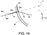
- the force 76 from the associated reinforcing structure 64a is arranged substantially radially, and more particularly in the corresponding radial notional plane 66a.
- the radial force 76 is taken up on the one hand by a compressive or pulling force 78 in the connecting rod 62, and on the other hand by a force 80 necessarily substantially tangential, in the ring 60, this force being also said membrane stress. Therefore, at each of the three stress introduction points of the ring, the latter tends to respond to the mechanical stresses of the reinforcement structures by a substantially tangential force, greatly limiting the risk of ovalization.
- the three connecting rods 62 respectively from the force introduction points 68a, 68b, 68c is associated with a fourth connecting rod 62 connecting the ring 60 to the casing 16, this fourth connecting rod being arranged symmetrically. relative to that attached to the third motor attachment, central symmetry center consisting of the axis 5.
- its outer end 62b is also arranged to be traversed, in front view, by the fictitious radial plane 66c passing by the longitudinal axis 5 and the force introduction point 68c concerned.
- each of the four connecting rods therefore extends in the same circumferential direction from its outer end 62b, for example clockwise as has been shown.
- the ring 60 can rotate around the central casing 16 while remaining coaxial therewith.
- the four rods 62 tangential to the casing 16 are then distributed in central central symmetry constituted by the longitudinal axis 5.
- the rods 62 arranged in the manner described above are always connected to the ring 60, which is not only connected to the force introduction points 68a, 68b, 68c, but also worn by a structure 86 of internal radial delineation of the annular channel of secondary flow 88 (of the English "IFS", Inlet Fan Structure).
- this structure 86 is arranged radially inwardly with respect to a structure 90 of external radial delineation of the annular channel of secondary flow (of the English "OFS", Outlet Fan Structure), itself located in the rear extension of the inner skins of the side boxes of the suspension pylon.
- the reinforcing structures 64a, 64b, 64c, running along the internal structure 80 play an additional role of bifurcating the air in the secondary flow of the turbojet.
- turbojet 2 is shown in a position as adopted when suspended under the wing. Nevertheless, here again, the particular configuration of the mounting means 62, described above, can be envisaged for any positioning of the turbojet engine, especially when it is attached to the rear fuselage, as shown on the figures 8 and 9 .
Landscapes
- Engineering & Computer Science (AREA)
- Chemical & Material Sciences (AREA)
- Combustion & Propulsion (AREA)
- Aviation & Aerospace Engineering (AREA)
- Mechanical Engineering (AREA)
- General Engineering & Computer Science (AREA)
- Structures Of Non-Positive Displacement Pumps (AREA)
Description
- La présente invention se rapporte de façon générale à un ensemble moteur pour aéronef, du type comprenant un turboréacteur, une nacelle enveloppant le turboréacteur, ainsi qu'un mât d'accrochage pourvu d'une structure rigide et d'une pluralité d'attaches moteur interposées entre une structure rigide du mât d'accrochage et le turboréacteur. Un tel ensemble est par exemple connu du document
US 5 226 288 qui décrit de plus toutes les caractéristiques du préambule de la revendication 1. - Le mât d'accrochage, également appelé « EMS » (de l'anglais « Engine Mounting Structure »), permet de suspendre le turboréacteur au-dessous de la voilure de l'aéronef, ou bien de monter ce turboréacteur au-dessus de cette même voilure, ou bien encore de le rapporter en partie arrière du fuselage. Il est en effet prévu pour constituer l'interface de liaison entre un turboréacteur et une partie structurale donnée de l'aéronef. Il permet de transmettre à la structure de cet aéronef les efforts générés par son turboréacteur associé, et autorise également le cheminement du carburant, des systèmes électriques, hydrauliques, et air entre le moteur et l'aéronef.
- La nacelle est quant à elle classiquement équipée de plusieurs capots enveloppant le turboréacteur et permettant un accès à ce dernier en position ouverte, ces capots étant connus sous les dénominations de capots de soufflante et de capots d'inverseur de poussée.
- De façon plus précise, sur certains ensembles moteurs de l'art antérieur, il est prévu un mât d'accrochage disposant d'une structure rigide comportant un caisson longitudinal ainsi que deux caissons latéraux solidaires du caisson longitudinal et agencés de part et d'autre de celui-ci, le mât comprenant également des moyens d'accrochage du turboréacteur sur la structure rigide, ces moyens comportant une première, seconde et troisième attaches moteur avant de reprise des efforts de poussée rapportées sur le carter de soufflante. Comme le montre schématiquement la
figure 1 illustrant une réalisation de l'art antérieur dans laquelle le moteur est destiné à être suspendu sous l'aile de l'aéronef, les trois attaches moteur avant reprenant les efforts de poussée sont agencées de sorte que la troisième attache moteur avant 8 passe par un plan diamétral P1 du turboréacteur, ici le plan de symétrie vertical du turboréacteur, tandis que les première et seconde attaches moteur 6a, 6b, respectivement destinées à être rapportées sur les deux caissons latéraux du mât, sont quant à elles disposées de part et d'autre de ce plan diamétral P1, et habituellement traversées par un autre plan diamétral P2 du turboréacteur, orthogonal au plan diamétral précité et correspondant ici au plan de symétrie horizontal du turboréacteur. - Par ailleurs, le turboréacteur comprend de façon classique un carter de soufflante 12, un carter intermédiaire 21 situé radialement vers l'intérieur par rapport au carter de soufflante et relié à ce dernier par une pluralité de bras structuraux 17 orientés de préférence radialement, ainsi qu'un carter central 16, également dit carter « core », prolongeant le carter intermédiaire 21 vers l'arrière. Enfin, il est noté que le carter central s'étend jusqu'à une extrémité arrière 19 de plus grande dimension, également dénommée carter d'éjection.
- Comme montré sur la
figure 2 , l'ensemble moteur comprend une structure annulaire de transfert d'efforts 60 entourant le carter central 16 et relié mécaniquement à ce dernier par l'intermédiaire de moyens de montage 62, comprenant habituellement une pluralité de bielles de raccordement. Comme cela est schématisé par les flèches 76, la structure annulaire 60 est par ailleurs raccordée à une pluralité de structures (non représentées) agencées extérieurement par rapport à celle-ci, et la sollicitant par exemple radialement, respectivement en une pluralité de points d'introduction d'efforts, généralement répartis circonférentiellement sur cette dernière. - Ainsi, la structure annulaire permet de faire passer des efforts entre le carter central et les structures extérieures, ces dernières pouvant par exemple être la structure de délimitation radiale externe du canal annulaire de flux secondaire (de l'anglais « OFS », Outlet Fan Structure), et/ou la structure de délimitation radiale interne du canal annulaire de flux secondaire (de l'anglais « IFS », Inlet Fan Structure).
- Cependant, dans les solutions de l'art antérieur, la disposition des bielles de raccordement précitées n'étant pas optimisée, le passage des efforts provoque des déformations de la structure annulaire et/ou du carter central, ce qui n'est bien entendu pas souhaitable.
- L'invention a donc pour but de proposer un ensemble moteur pour aéronef remédiant au moins partiellement aux problèmes mentionnés ci-dessus, relatifs aux réalisations de l'art antérieur.
- Pour ce faire, l'invention a pour objet un ensemble moteur pour aéronef selon les caractéristiques de la revendication 1.
- L'invention présente l'avantage de placer, en vue de face, chaque point d'introduction d'efforts et l'extrémité extérieure de la bielle de raccordement dans un même plan fictif radial, dans lequel se trouve également agencé l'effort introduit dans la structure annulaire, par la structure extérieure de même plan associée au point d'introduction d'efforts concerné. Par conséquent, l'effort précité, sensiblement radial ou non, est repris conjointement par un effort de compression ou de traction dans la bielle, ainsi que par un effort nécessairement sensiblement tangentiel dans la structure annulaire, également dit effort de membrane. De ce fait, au niveau de chacun des points d'introduction d'efforts de la structure annulaire, celle-ci tend à répondre aux sollicitations mécaniques des structures extérieures par un effort sensiblement tangentiel, limitant fortement ses déformations, et l'empêchant en particulier de « s'ovaliser ».
- Par ailleurs, les bielles de raccordement étant disposées tangentiellement par rapport au carter central sur lequel elles sont raccordées, les déformations de ce carter sont également fortement limitées.
- L'invention prévoit donc globalement de fournir une jonction mécanique mieux optimisée entre la structure annulaire et le carter central, permettant d'assurer une reprise satisfaisante des efforts transitant par les structures extérieures raccordées à la structure annulaire.
- De préférence, comme évoqué ci-dessus, lesdites structures sont agencées sensiblement radialement et sollicitent sensiblement radialement ladite structure annulaire. Chaque plan fictif est donc sensiblement radial, passant par l'axe longitudinal du turboréacteur.
- De préférence, lesdites bielles de raccordement sont disposées sensiblement dans un même plan transversal du turboréacteur.
- Toujours préférentiellement, afin d'autoriser au mieux la dilatation thermique du carter central par rapport à la structure annulaire qui l'entoure, lesdites bielles de raccordement présentent des extrémités intérieure et extérieure montées de façon rotulée.
- De préférence, lesdites bielles de raccordement s'étendent toutes dans le même sens circonférentiel à partir de leur extrémité extérieure. Avec cette configuration, en cas de dilatation thermique différentielle entre l'anneau et le carter ou les bielles, l'anneau peut avantageusement tourner autour du carter central, tout en restant coaxial à celui-ci.
- De préférence, l'ensemble moteur comprend en outre un mât d'accrochage disposant d'une structure rigide et de moyens d'accrochage dudit turboréacteur sur la structure rigide, lesdits moyens d'accrochage comportant une première, seconde et troisième attaches moteur avant de reprise des efforts de poussée rapportées sur le carter de soufflante, et agencées de sorte que ladite troisième attache moteur avant passe par un premier plan diamétral du turboréacteur, lesdites première et seconde attaches moteur avant étant disposées de part et d'autre de ce premier plan diamétral, et en ce que à chacune desdites première, seconde et troisième attaches moteur avant est associée une structure de renfort formant plan de cisaillement formée par l'une desdites structures précitées, et raccordée fixement :
- au niveau de la structure annulaire en un premier point d'ancrage formant ledit point d'introduction d'effort dans ladite structure annulaire ;
- au niveau du carter de soufflante en un second point d'ancrage ; et
- au niveau d'un bras structural ou du carter intermédiaire en un troisième point d'ancrage,
- La présence de ces structures de renfort sollicitées en cisaillement permet de rigidifier le turboréacteur dans les trois plans fictifs précités, impliquant une limitation de la flexion du carter central et du carter intermédiaire, même en cas de sollicitations inertielles dans ces plans. Les performances globales de l'ensemble moteur s'en trouvent améliorées.
- Par ailleurs, cette adjonction des structures de renfort procure une rigidification des bras structuraux dans et à proximité des deux plans fictifs associés aux première et seconde attaches, c'est-à-dire là où les bras sont traditionnellement les plus sollicités. Il en résulte avantageusement une baisse des déformations des bras structuraux. Par conséquent, le carter de soufflante a moins tendance à s'ouvrir dans le plan des bras structuraux, ce qui limite fortement l'effet d'ovalisation rencontré avec des première et seconde attaches moteur diamétralement opposées. Ceci se traduit par un meilleur rendement de la soufflante, et donc par un meilleur rendement global du turboréacteur.
- De plus, les structures de renfort formant plan de cisaillement jouent parfaitement leur rôle grâce à la non-déformation évoquée ci-dessus de la structure annulaire sur laquelle ils sont raccordés, par l'intermédiaire des points d'introduction d'efforts.
- Toujours de manière préférentielle, lesdites structures de renfort sont dépourvues de raccordement mécanique direct avec ledit mât, ce qui permet d'éviter d'introduire des efforts additionnels dans ce dernier. Les moyens d'accrochage précités peuvent de ce fait rester isostatiques, malgré la présence des structures de renfort. A titre indicatif, pour des raisons identiques, on fait également en sorte que lesdites structures de renfort sont dépourvues de raccordement mécanique direct avec la nacelle de l'ensemble moteur concerné.
- De préférence, lesdites première et seconde attaches moteur avant sont rapportées sur le carter de soufflante respectivement en deux points situés au-delà du second plan diamétral du turboréacteur orthogonal au premier plan diamétral, par rapport à ladite troisième attache moteur avant. Alternativement, les première et seconde attaches moteur avant pourraient être rapportées sur le carter de soufflante respectivement en deux points situés dans ce second plan diamétral, sans sortir du cadre de l'invention.
- De préférence, lesdites première et seconde attaches moteur avant de reprise des efforts de poussée sont situées de façon symétrique par rapport audit premier plan diamétral défini par l'axe longitudinal du turboréacteur parallèle à une direction longitudinale de celui-ci, et une première direction dudit turboréacteur orthogonale à la direction longitudinale.
- Toujours préférentiellement, les première et seconde attaches moteur avant sont chacune conçues de manière à reprendre des efforts s'exerçant selon la direction longitudinale et selon ladite première direction du turboréacteur, et ladite troisième attache moteur avant est conçue de manière à reprendre des efforts s'exerçant selon la direction longitudinale et selon une seconde direction du turboréacteur, orthogonale à ladite première direction et à la direction longitudinale.
- A titre indicatif, il est noté que dans les cas où le turboréacteur est destiné à être monté au-dessus de la voilure de l'aéronef ou suspendu au-dessous de celle-ci, les première et seconde directions orthogonales entre elles et orthogonales à la direction longitudinale sont préférentiellement les directions verticale et transversale du turboréacteur, respectivement. En revanche, bien que cela puisse également être le cas dans le cadre de l'accrochage de l'ensemble moteur en partie arrière du fuselage de l'aéronef, il se peut que les première et seconde directions soient chacune inclinées par rapport aux directions verticale et transversale du turboréacteur.
- Dans cette configuration, lesdits moyens d'accrochage sont uniquement constitués par les attaches avant précitées, fixées au carter de soufflante du turboréacteur, et formant un système de reprise isostatique. D'une façon plus générale, on fait en sorte que les seuls moyens d'accrochage fixés au carter de soufflante soient lesdites première, seconde et troisième attaches moteur, même dans d'autres cas où une attache moteur additionnelle est prévue entre la structure rigide du mât et le carter central, toujours de manière à former un système de reprise isostatique.
- De préférence, comme évoqué ci-dessus, ladite première direction du turboréacteur correspond à une direction verticale de celui-ci, et ladite seconde direction du turboréacteur correspond à une direction transversale de celui-ci.
- Un autre objet de la présente invention concerne un aéronef comprenant au moins un ensemble moteur tel que décrit ci-dessus, assemblé sur une aile ou sur une partie arrière de fuselage de cet aéronef.
- D'autres avantages et caractéristiques de l'invention apparaîtront dans la description détaillée non limitative ci-dessous.
- Cette description sera faite au regard des dessins annexés parmi lesquels ;
- les
figures 1 et 2 , déjà décrites, représentent un ensemble moteur pour aéronef conforme à l'art antérieur ; - la
figure 3 représente une vue de côté d'un ensemble moteur pour aéronef, selon un mode de réalisation préféré de la présente invention ; - la
figure 4 représente une vue en perspective de l'ensemble représenté sur lafigure 3 , la structure rigide du mât, les structures de renfort et la nacelle ayant été retirées pour laisser plus clairement apparaître les attaches moteur ; - la
figure 5 représente une vue schématique de face correspondant à celle de lafigure 4 , illustrant le positionnement particulier des attaches moteur ; - la
figure 6 représente une vue partielle et agrandie en perspective du mât d'accrochage selon le mode de réalisation préféré ; - la
figure 7 représente une vue en coupe prise selon le plan transversal P' de lafigure 6 ; - la
figure 8 représente une vue en perspective d'un mât d'accrochage appartenant à un ensemble moteur pour aéronef selon un autre mode de réalisation préféré de la présente invention ; - la
figure 9 représente une vue en coupe prise selon le plan transversal P' de lafigure 8 , traversant la structure rigide du mât d'accrochage ; - la
figure 10 représente une vue en coupe transversale, illustrant les structures de renfort reliant le carter de soufflante au carter central, cette figure correspondant également à une vue en coupe prise le long de la ligne X-X de lafigure 11 ; - la
figure 11 représente une vue en coupe prise le long de la ligne XI-XI de lafigure 10 ; - la
figure 12 représente une vue en coupe prise le long de la ligne XII-XII de lafigure 10 ; - la
figure 13 représente une vue en coupe transversale schématisant les moyens de montage rapportés entre la structure annulaire de transfert d'efforts, et le carter central du turboréacteur ; - la
figure 13a représente une vue similaire à celle de lafigure 13 , les moyens de montage se trouvant sous une forme alternative de réalisation ; - la
figure 14 représente une vue partielle et agrandie de celle montrée sur lafigure 13 , schématisant la répartition des efforts sur la structure annulaire, au niveau d'un point d'introduction d'efforts ; et - la
figure 15 représente un autre mode de réalisation préféré, correspondant à une vue en coupe prise le long de la ligne XV-XV de lafigure 13 . - En référence à la
figure 3 , on voit un ensemble moteur 1 pour aéronef selon un mode de réalisation préféré de la présente invention, cet ensemble 1 étant destiné à être fixé sous une aile d'aéronef (non représentée). - Globalement, l'ensemble moteur 1, également appelé système propulsif intégré, est composé d'un turboréacteur 2, d'une nacelle 3 (montrée en pointillés pour des raisons clarté), et d'un mât d'accrochage 4 pourvu de moyens d'accrochage du turboréacteur sur ce mât, ces moyens étant de préférence constitués d'une pluralité d'attaches moteur 6a, 6b, 8, rapportées fixement sur une structure rigide 10 du mât d'accrochage (l'attache 6b étant masquée par l'attache 6a sur cette
figure 3 ). A titre indicatif, il est noté que l'ensemble 1 comporte une autre série d'attaches (non représentées) permettant d'assurer la suspension de cet ensemble 1 sous la voilure de l'aéronef. - Dans toute la description qui va suivre, par convention, on appelle X la direction longitudinale du mât 4 qui est également assimilable à la direction longitudinale du turboréacteur 2, cette direction X étant parallèle à un axe longitudinal 5 de ce turboréacteur 2. D'autre part, on appelle Y la direction orientée transversalement par rapport au mât 4 et également assimilable à la direction transversale du turboréacteur 2, et Z la direction verticale ou de la hauteur, ces trois directions X, Y et Z étant orthogonales entre-elles.
- D'autre part, les termes « avant » et « arrière » sont à considérer par rapport à une direction d'avancement de l'aéronef rencontrée suite à la poussée exercée par le turboréacteur 2, cette direction étant représentée schématiquement par la flèche 7.
- Sur la
figure 3 , on peut voir que seules les attaches moteur 6a, 6b, 8 et la structure rigide 10 du mât d'accrochage 4 ont été représentées. Les autres éléments constitutifs non représentés de ce mât 4, tels que les moyens d'accrochage de la structure rigide 10 sous la voilure de l'aéronef, ou encore la structure secondaire assurant la ségrégation et le maintien des systèmes tout en supportant des carénages aérodynamiques, sont des éléments classiques identiques ou similaires à ceux rencontrés dans l'art antérieur, et connus de l'homme du métier. Par conséquent, il n'en sera fait aucune description détaillée. - D'autre part, le turboréacteur 2 dispose d'une conception identique ou similaire à celle montrée sur la
figure 1 , à savoir comprenant à l'avant un carter de soufflante 12 de grande dimension délimitant un canal annulaire de soufflante 14, un carter intermédiaire 21 et des bras structuraux 17 (non représentés sur lafigure 3 ), également dits aubages directeurs de sortie, ainsi qu'un carter central 16 disposant d'une extrémité arrière 19. - Comme cela ressort de ce qui précède, il s'agit ici préférentiellement d'un turboréacteur disposant d'un fort taux de dilution.
- Comme on peut l'apercevoir sur la
figure 3 , une première attache moteur avant 6a ainsi qu'une seconde attache moteur avant 6b sont toutes deux destinées à être fixées sur le carter de soufflante 12, de façon symétrique par rapport à un plan P1 dit premier plan diamétral défini par l'axe 5 et la direction Z, ce plan vertical P1 traversant une troisième attache moteur avant 8 également fixée sur le carter de soufflante 12, les trois attaches étant de préférence toutes traversées par un plan orthogonal à l'axe 5. - En référence à présent à la
figure 4 , on peut voir que la première attache 6a et la seconde attache 6b représentées schématiquement sont effectivement disposées de façon symétrique par rapport au premier plan diamétral P1 du turboréacteur, et de préférence agencées toutes les deux sur une partie annulaire périphérique du carter de soufflante 12, et plus précisément sur l'arrière de cette même partie. Dans ce mode de réalisation préféré, elles sont disposées sous un plan P2 dit second plan diamétral du turboréacteur, qui est orthogonal au premier, et donc horizontal. Les deux points de raccordement 6'a et 6'b de ces attaches 6a, 6b sur le carter 12 sont donc situés de manière à ce que le second plan P2 soit disposé entre d'une part ces deux points 6'a et 6'b, et d'autre part un point de raccordement 8' de l'attache moteur 8 sur ce même carter, en vue de face selon l'axe 5, comme celle de lafigure 5 . - Sur cette figure en vue selon l'axe 5, on peut voir qu'un angle A1 ayant comme centre cet axe longitudinal 5, entre les points d'ancrage 8' et 6'a de la troisième et de la première attache moteur, est strictement supérieur à 90° et de préférence compris entre 90 et 110° non-inclus. De manière analogue, un angle A2 ayant comme centre cet axe longitudinal 5, entre les points d'ancrage 8' et 6'b de la troisième et de la seconde attache moteur, est strictement inférieur à 270°, et de préférence compris entre 250 et 270° non-inclus.
- Cette disposition des attaches 6a, 6b permet de solliciter davantage l'attache moteur 8, et donc de limiter les effets parasites d'ovalisation du carter de soufflante rencontrés dans les réalisations de l'art antérieur, avec les première et seconde attaches moteur disposées dans le plan P2. De plus, elle permet de contrer/compenser un couple d'axe parallèle à la direction Y, s'exerçant sur le turboréacteur, résultant des efforts axiaux transitant par cette même troisième attache 8. Quoi qu'il en soit, bien que cette disposition soit préférée, l'invention s'applique également à d'autres dispositions des attaches moteur 6a, 6b, 8.
- A titre indicatif, il est noté que les attaches moteur 6a, 6b, 8 sont réalisées de manière conventionnelle, par exemple du type intégrant des ferrures et des axes, les points d'ancrage / de raccordement précités 6'a, 6'b, 8' correspondant aux points de contact entre la structure de ces attaches et la structure du carter de soufflante.
- Comme cela est montré schématiquement par les flèches de la
figure 4 , chacune des première et seconde attaches moteur avant 6a, 6b est conçue de manière à pouvoir reprendre des efforts générés par le turboréacteur 2 selon la direction X et selon la direction Z, mais pas ceux s'exerçant selon la direction Y. - De cette manière, les deux attaches 6a, 6b éloignées l'une de l'autre assurent conjointement la reprise du moment s'exerçant selon la direction X, et celle du moment s'exerçant selon la direction Z. Toujours en référence à la
figure 4 , on peut voir que la troisième attache avant 8, située sur la partie la plus haute du carter de soufflante 12, donc sur la partie la plus haute de la partie annulaire périphérique, est conçue de manière à pouvoir reprendre des efforts générés par le turboréacteur 2 selon la direction X et selon la direction Y, mais pas ceux s'exerçant selon la direction Z. De cette manière, cette troisième attache 8 assure conjointement avec les attaches 6a, 6b la reprise du moment s'exerçant selon la direction Y. - L'avantage de cette configuration non limitative réside dans le fait que toutes les attaches moteur sont montées sur le carter de soufflante, de sorte que le flux secondaire n'est aucunement perturbé par ces attaches, entraînant ainsi un gain significatif en termes de performances globales du moteur. De plus, les trois attaches forment ensemble un système de reprise isostatique.
- En référence à présent à la
figure 6 , on voit un exemple de réalisation de la structure rigide 10 du mât d'accrochage 4. Tout d'abord, il est indiqué que cette structure rigide 10, également appelée structure primaire, est de préférence conçue de manière à présenter une symétrie par rapport au plan diamétral P1 indiqué ci-dessus, c'est-à-dire par rapport au plan vertical défini par l'axe longitudinal 5 du turboréacteur 2, et la direction Z. A titre indicatif, cela est généralement le cas lorsque le moteur est suspendu ou monté au-dessus de la voilure, mais pas nécessairement rencontré lorsqu'il est assemblé à l'arrière du fuselage. En effet, dans ce dernier cas qui sera détaillé en référence auxfigures 8 et9 , la structure rigide 10 peut présenter un plan de symétrie autre en fonction de son orientation par rapport au fuselage arrière, par exemple un plan de symétrie sensiblement horizontal ou incliné par rapport à l'horizontale, ou bien encore ne présenter aucun plan de symétrie. Cela se produit notamment lorsque les deux caissons latéraux qui seront décrits ci-après, solidaires et disposés de part et d'autre d'un caisson longitudinal dit caisson central, ne présentent pas une même longueur circonférentielle. - Ainsi, la structure rigide 10 comporte un caisson longitudinal 22, dit caisson central longitudinal, et également appelé caisson de torsion, qui s'étend d'un bout à l'autre de la structure 10 dans la direction X, parallèlement à cette même direction. A titre indicatif, ce caisson 22 peut être formé par l'assemblage de deux longerons ou panneaux latéraux 30 s'étendant selon la direction X dans des plans XZ parallèles, et raccordés entre eux par l'intermédiaire de nervures transversales 25 qui sont quant à elles orientées dans des plans YZ parallèles. En outre, un longeron supérieur 35 et un longeron inférieur 36 sont également prévus pour fermer le caisson 22.
- Deux caissons latéraux 24a, 24b viennent compléter la structure rigide 10 dont le caisson central 22 se situe au niveau d'une portion supérieure de cette même structure 10, chacun des deux caissons 24a, 24b étant solidaire du caisson central de torsion 22 et faisant saillie de part et d'autre de celui-ci selon la direction Y, et vers le bas. A titre indicatif, il est noté que les caissons 22, 24a, 24b pourraient être réalisés de manière à ne former qu'un seul et unique caisson, sans sortir du cadre de l'invention.
- De préférence, ces caissons latéraux rapportés solidairement de part et d'autre à l'avant du caisson central 22, présentent chacun une peau intérieure de fermeture de caisson 26a, 26b, également dite peau inférieure, orientée vers le turboréacteur et délimitant conjointement une partie d'une surface fictive 32 sensiblement cylindrique de section circulaire, et d'axe longitudinal 34 parallèle au caisson central 22 et à la direction X, comme cela est visible sur la
figure 6 . - En d'autres termes, ces deux peaux 26a, 26b disposent chacune d'au moins une partie avec une courbure adaptée pour pouvoir se positionner autour et au contact de cette surface fictive 32. On prévoit avantageusement que les peaux 26a, 26b participent alors à la délimitation radiale externe d'un canal annulaire de flux secondaire (non représenté), sachant qu'il est tout de même envisageable de prévoir un revêtement de protection acoustique sur ces mêmes peaux de fermeture, indifféremment sur leurs faces intérieures ou extérieures. Alternativement, il est possible de faire en sorte que les caissons latéraux soient entièrement situés au-dessus du carter de soufflante, sans sortir du cadre de l'invention.
- A titre indicatif, il est précisé que l'axe 34 est de préférence confondu avec l'axe longitudinal 5 du turbopropulseur 2.
- Par ailleurs, le caisson latéral 24a, ici identique et symétrique au caisson latéral 24b, comporte une peau extérieure de fermeture de caisson 44a, tandis que le caisson latéral 24a comporte lui aussi une peau extérieure de fermeture de caisson 44b.
- Ces peaux extérieures de fermetures 44a, 44b, également appelées peaux supérieures, constituent de préférence chacune une partie de la surface aérodynamique extérieure de la nacelle, impliquant avantageusement qu'au moins une partie du mât fait partie intégrante de la nacelle.
- La
figure 7 représente une vue en coupe prise selon un plan P' transversal traversant de façon quelconque les caissons latéraux 24a, 24b. - Sur cette figure, on peut effectivement voir que les deux peaux intérieures de fermeture de caisson 26a, 26b délimitent avec une partie de leur surface externe une partie de la surface fictive 32 sensiblement cylindrique de section circulaire. Il est noté que pour créer le moins de perturbation possible du flux secondaire s'échappant du canal annulaire de soufflante 14, le diamètre de la surface fictive cylindrique 32 est de préférence sensiblement identique au diamètre de la surface externe cylindrique de la partie annulaire du carter de soufflante 12. Cette spécificité va bien entendu dans le sens de celle visant à prévoir que les peaux 26a, 26b participent à la délimitation radiale externe de ce canal annulaire de flux secondaire.
- D'autre part, comme on peut le voir sur la
figure 7 , les éléments du caisson central 22 ne font saillie que sur une très petite distance à l'intérieur de l'espace 38 délimité par la surface fictive 32, de sorte qu'ils ne perturbent pas non plus significativement l'écoulement du flux d'air secondaire. Cela s'explique notamment par le fait que les longerons latéraux 30 disposent d'une hauteur selon la direction Z qui est extrêmement petite par rapport au diamètre des surfaces fictive 32 et externe 18. - En référence conjointement aux
figures 6 et7 , les peaux 26a, 44a sont raccordées l'une à l'autre par l'intermédiaire d'un cadre de fermeture avant 28a et d'un cadre de fermeture arrière 46a, ces cadres 28a, 46a étant donc orientés transversalement et situés respectivement à l'avant et à l'arrière du caisson 24a. En outre, une plaque de fermeture 48a située en dessous du plan P2 vient fermer une partie inférieure du caisson 24a, et relie donc l'extrémité inférieure des cadres 28a, 46a et des peaux 26a, 44a. - Naturellement, le caisson latéral 24b comporte des éléments 26b, 44b, 28b, 46b et 48b, respectivement identiques aux éléments 26a, 44a, 28a, 46a et 48a du caisson 24a, ces deux caissons étant par exemple susceptibles de porter, de préférence de manière articulée, des capots de la nacelle.
- Les deux peaux 26a, 26b sont de préférence réalisées d'un seul tenant et reliées entre elles au niveau de leur partie supérieure par l'intermédiaire d'une plaque de jonction 50 orientée selon un plan XY, et située au contact du longeron inférieur 36 du caisson central 22. De façon analogue, on peut aussi prévoir que les deux cadres de fermeture avant 28a, 28b sont réalisés d'un seul tenant et reliés entre eux au niveau de leur partie supérieure par l'intermédiaire d'un cadre de fermeture avant 31 du caisson 22, ce cadre 31 étant orienté selon un plan YZ. Par conséquent, dans cette configuration, les cadres 28a, 28b, 31 réalisés d'un seul tenant sont donc agencés dans un même plan YZ, et constituent une extrémité avant de la structure rigide 10 du mât 4.
- Ainsi, la structure rigide 10 du mât d'accrochage 4 est tout à fait adaptée pour supporter les attaches moteur avant 6a, 6b, 8, puisque celles-ci peuvent être facilement fixées sur la pièce transversale réalisée d'un seul tenant intégrant les cadres 28a, 28b et 31, comme montré sur la
figure 1 , et présentant par exemple une forme générale de U, tout comme l'ensemble de la structure rigide en vue de face. - Une solution alternative pourrait être envisagée, dans laquelle les caissons latéraux formeraient une barrique semi-cylindrique et non plus en U, des éléments structuraux additionnels étant alors prévus sous ces caissons, afin de déporter les première et seconde attaches moteur sous le second plan diamétral P2. Cette configuration est particulièrement intéressante dans le cadre d'une mise en place du turboréacteur sur le mât par un mouvement vertical, par le dessous.
- A titre d'exemple indicatif, la totalité des éléments constitutifs de la structure rigide 10 qui vient d'être décrite est réalisée à l'aide de matériaux métalliques, tels que l'acier, l'aluminium, le titane, ou encore à l'aide de matériaux composites, de préférence en carbone.
- Il est rappelé qui si les caissons latéraux 24a, 24b peuvent effectivement présenter une longueur circonférentielle différente, principalement dans le cas de l'accrochage de l'ensemble en partie arrière du fuselage, il est également précisé que dans ce dernier cas, ces caissons pourraient être rapportés sur le caisson central 22 à une autre position qu'en partie avant de celui-ci, sans sortir du cadre de l'invention.
- A cet égard, en référence à présent aux
figures 8 et9 , on voit la structure rigide 10 d'un mât d'accrochage appartenant à un ensemble moteur selon un autre mode de réalisation préféré de la présente invention, dont la particularité est d'être destinée à se rapporter en partie arrière d'un fuselage 80 de l'aéronef. - Cette structure rigide 10 dispose d'une conception sensiblement identique à celle décrite dans le mode de réalisation présenté ci-dessus, comme en témoignent les références numériques correspondant à des éléments identiques ou similaires à ceux décrits précédemment.
- On peut apercevoir que la principale différence, résultant de l'accrochage en partie arrière du fuselage 80, réside dans l'inclinaison de cette structure rigide 10, dans la mesure où les deux caissons latéraux 24a, 24b forment à présent ensemble une portion d'une enveloppe/cage sensiblement cylindrique qui n'est plus située autour d'un demi-diamètre supérieur, mais agencée autour d'un demi-diamètre sensiblement latéral de ce même turboréacteur (non représenté).
- Plus précisément, la structure rigide 10 est de préférence conçue de manière à présenter une symétrie par rapport au plan diamétral P1 qui n'est plus vertical, mais défini par l'axe longitudinal 5 du turboréacteur 2 et une première direction Z' orthogonale à la direction X, cette première direction Z' étant inclinée par rapport aux directions Z et Y précitées, correspondant respectivement aux directions verticale et transversale du turboréacteur. De préférence, ce plan P1 peut être tel qu'il monte en s'écartant du fuselage 80, d'un angle par exemple compris entre environ 10° et 60° par rapport à l'horizontale, c'est-à-dire par rapport à un plan XY quelconque.
- La première attache moteur avant 6a ainsi que la seconde attache moteur avant 6b sont toutes deux destinées à être fixées sur le carter de soufflante, de façon symétrique par rapport au plan P1 défini ci-dessus, comme le montre la
figure 8 . On prévoit alors que les première et seconde attaches moteur avant 6a, 6b sont disposées au-delà du plan diamétral P2 orthogonal à P1, vis-à-vis de l'attache 8. Ici encore, cela se résume par le fait que le plan diamétral P2 se situe entre d'une part les deux attaches 6a, 6b, et d'autre part l'attache moteur 8. - Ici, le plan P2 est défini par l'axe longitudinal 5 et une seconde direction Y' orthogonale à la direction X et à la première direction Z' , de sorte qu'il est donc également incliné par rapport aux directions Z et Y.
- Comme cela est montré schématiquement par les flèches de la
figure 8 , chacune des première et seconde attaches moteur avant 6a, 6b est conçue de manière à pouvoir reprendre des efforts générés par le turboréacteur 2 selon la direction X et selon la première direction Z', mais pas ceux s'exerçant selon la direction Y'. - De cette manière, les deux attaches 6a, 6b fortement éloignées l'une de l'autre assurent conjointement la reprise du moment s'exerçant selon la direction X, et celle du moment s'exerçant selon la direction Z'.
- Toujours en référence à la
figure 8 , on peut voir une troisième attache moteur avant 8 représentée schématiquement et aussi destinée à être fixée sur la partie annulaire périphérique du carter de soufflante (non représenté), également de préférence sur l'arrière de cette partie. En ce qui concerne cette troisième attache avant 8, traversée fictivement par le plan P1 indiqué ci-dessus, elle est conçue de manière à pouvoir reprendre uniquement des efforts générés par le turboréacteur 2 selon la direction X et selon la direction Y', et donc pas ceux s'exerçant selon la directions Z'. - De cette manière, cette troisième attache 8, assure conjointement avec les deux autres attaches 6a, 6b la reprise du moment s'exerçant selon la seconde direction Y'.
- Enfin, même si cela n'a pas été représenté, il est noté qu'il est de préférence prévu un ou plusieurs capots de nacelle montés sur la structure rigide 10, et en particulier sur les caissons latéraux 24a, 24b.
- Sur les
figures 10 à 12 , le turboréacteur intègre de plus des structures de renfort reliant le carter de soufflante au carter central. Sur les figures, le turboréacteur 2 est représenté dans une position telle qu'adoptée lorsqu'il est suspendu sous la voilure. Néanmoins, le mode de réalisation décrit peut s'envisager pour tout positionnement du turboréacteur, notamment lorsqu'il est rapporté en partie arrière de fuselage, tel que cela est montré sur lesfigures 8 et9 . - Tout d'abord, il est prévu une structure annulaire de transfert d'efforts 60, également appelée jante ou anneau, entourant le carter central 16 et centré sur l'axe 5. Cet anneau 60, espacé radialement du carter central 16, est relié mécaniquement à ce dernier par l'intermédiaire de moyens de montage 62, du type bielles, tel que cela sera détaillé ci-après. De préférence, cet anneau 60 se situe vers l'arrière du carter central 16, par exemple en aval de la chambre de combustion, et plus préférentiellement au niveau d'un carter inter-turbine en vis-à-vis d'un élément fixe de structure, idéalement à la fin du carter de turbine haute pression. Pour un meilleur support, il se situe préférentiellement au droit d'un palier d'arbre du turboréacteur.
- Tout d'abord, il est prévu une structure de renfort formant plan de cisaillement, associée à chacune des première et seconde attaches moteur 6a, 6b.
- Ainsi, en ce qui concerne la première attache moteur 6a, une structure de renfort 64a formant plan de cisaillement est agencée dans un plan fictif radial 66a passant par l'axe 5, et passant également par le point d'ancrage 6'a de cette attache 6a.
- Comme cela est le mieux visible sur la
figure 11 , la structure 64a prend de préférence une forme plane sensiblement triangulaire, éventuellement trouée pour un gain de masse. Le triangle est raccordé fixement au niveau de l'anneau 60 en un premier point d'ancrage 68a, au niveau du carter de soufflante 12, à proximité du point 6'a situé dans le même plan fictif 66a, en un second point d'ancrage 70a, et au niveau de la jonction entre un bras structural 17 et le carter intermédiaire 21, en un troisième point d'ancrage 72a. Ainsi, la structure triangulaire 64a formant plan de cisaillement présente une base parallèle et longeant le bras structural 17 placé dans le plan fictif 66a, ce dernier étant ici incliné par rapport aux directions Y et Z, en raison du déport de l'attache 6a en dessous du plan diamétral P2. - Le plan fictif 66a, dans lequel s'inscrit la structure de renfort triangulaire 64a, est ici radial, à savoir qu'il passe par l'axe longitudinal 5. Néanmoins, il pourrait être disposé autrement, à savoir être parallèle à l'axe longitudinal 5, sans l'intégrer. Cela est notamment le cas lorsque les bras structuraux ne sont eux-mêmes pas radiaux, mais inclinés dans un plan transversal de manière à ce que leur axe n'intercepte pas l'axe longitudinal 5. Dans une telle configuration, on continue de préférence à faire en sorte que la structure triangulaire 64a présente une base parallèle et longeant le bras structural 17, placé dans le plan fictif 66a. En d'autres termes, on prévoit de préférence que la structure triangulaire 64a se trouve dans le prolongement arrière de l'un des bras structuraux 17, ce bras et la structure 64a étant donc situés dans le même plan fictif 66a. Il est noté que cette spécificité est également applicable pour chacune des autres structures de renfort décrites ci-dessous.
- De la même manière, une conception identique ou similaire est adoptée pour la seconde attache 6b. Par conséquent, sur les figures, les références numériques attachées aux éléments en relation avec la structure de renfort 64b formant plan de cisaillement agencée dans un plan fictif radial 66b, portent donc la lettre « b », à la place de la lettre « a » utilisée pour des éléments identiques en lien avec la structure de renfort 64a.
- Ainsi, les structures 64a, 64b se retrouvent symétriques par rapport au plan diamétral P1, correspondant également à un autre plan fictif radial 66c, dans lequel se trouve une troisième structure de renfort 64c formant plan de cisaillement, attachée à la troisième attache moteur 8. A cet égard, il est noté que dans le cas envisageable où les attaches moteur 6a, 6b seraient disposées dans le plan P2, et non en dessous de celui-ci, les deux plans fictifs radiaux 64a, 64b seraient alors confondus avec ce plan P2.
- Ici aussi, sur les figures, les références numériques attachées aux éléments en relation avec la structure de renfort 64c formant plan de cisaillement agencée dans un plan fictif radial 66c, portent donc la lettre « c », à la place de la lettre « a » utilisée pour des éléments identiques en lien avec la structure de renfort 64a.
- Les trois structures 64a, 64b, 64c, de préférence sensiblement identiques, permettent globalement de rigidifier le carter central 16, limitant ainsi sa flexion, même en cas de sollicitations inertielles s'exerçant dans les plans fictifs 66a, 66b, 66c, le dernier correspondant ici au plan vertical. De plus, elles permettent une limitation de la déformation des bras structuraux 17 dans ces plans fictifs et à proximité, entraînant avantageusement une limitation de l'effet d'ovalisation du carter de soufflante 12.
- De préférence, les structures 64a, 64b, 64c peuvent chacune jouer le rôle bifurcations de l'air dans le flux secondaire du turboréacteur, ces bifurcations ayant pour principale fonction d'intégrer le passage de systèmes et/ou présentant un traitement acoustique, tout en constituant des surfaces aérodynamiques.
- Enfin, pour la conservation d'une reprise d'efforts isostatique, les structures de renfort sont dépourvues de raccordement mécanique direct avec ledit mât, et également avec la nacelle.
- En référence à présent aux
figures 13 et14 , on peut voir l'une des particularités de la présente invention, résidant dans la conception des moyens de montage 62 rapportés entre la structure annulaire de transfert d'efforts 60, et le carter central 16. - Tout d'abord, il est noté que les points d'ancrage 68a, 68b, 68c cités ci-dessus forment chacun un point d'introduction d'efforts dans l'anneau 60, ces points étant répartis circonférentiellement le long de ce dernier. De plus, en raison de l'orientation préférentielle radiale des structures de renfort précitées associées à ces points 68a, 68b, 68c, l'effort sollicitant l'anneau 60 est également orienté radialement, à savoir passant par une direction traversant l'axe 5, sur lequel est centré ce même anneau. Néanmoins, il est rappelé que les structures de renfort pourraient être orientées autrement que radialement, sans sortir du cadre de l'invention.
- A chacun de ces trois points 68a, 68b, 68c est associée au moins une bielle de raccordement 62, chaque bielle étant, en vue de face selon l'axe 5 comme sur la
figure 13 , disposée tangentiellement par rapport au carter central 16. Plus précisément, les bielles 62 sont de préférence toutes disposées sensiblement dans un même plan transversal du turboréacteur. - On prévoit de préférence qu'une bielle unique 62 est issue de chacun des points supérieur 68c et inférieurs 68a, 68b.
- Pour chacune de ces bielles 62, il est prévu une extrémité intérieure 62a raccordée de façon rotulée sur le carter central 16, ainsi qu'une extrémité extérieure 62b raccordée de façon rotulée sur l'anneau 60. Plus particulièrement, cette extrémité extérieure 62b est agencée de manière à être traversée, en vue de face, par le plan fictif radial 66a, 66b, 66c passant par l'axe longitudinal 5 et le point d'introduction d'efforts 68a, 68b, 68c concerné. A titre indicatif, il en résulte, d'une manière générale, que pour une attache moteur donnée, le point d'ancrage de l'attache sur le carter de soufflante, le point d'ancrage de la structure de renfort associée sur le carter de soufflante, la structure de renfort elle-même, le point d'introduction d'efforts dans l'anneau formant point d'ancrage de la structure de renfort sur cet anneau, ainsi que l'extrémité extérieure de la bielle associée, sont tous agencés dans un même plan fictif radial, dans lequel se situe donc également préférentiellement l'un des bras structuraux reliant les carters 12 et 16.
- La nature rotulée de la fixation des extrémités des bielles 62 permet de gérer au mieux la dilatation thermique du carter central par rapport à la structure annulaire 60 qui l'entoure, et ce à la fois dans la direction radiale et dans la direction longitudinale. En effet, les bielles rotulées positionnées comme décrit ci-dessus sont facilement capables d'accompagner les déformations du carter central dans ces deux directions, lorsque ce dernier se dilate, sans provoquer de contraintes néfastes.
- De plus, comme visible sur la
figure 13 , chacune des trois bielles s'étend dans le même sens circonférentiel à partir de son extrémité extérieure 62b, par exemple le sens horaire comme cela a été représenté. Avec cette configuration, en cas de dilatation thermique différentielle entre l'anneau 60 et le carter 16 ou les bielles 62, l'anneau 60 peut tourner autour du carter central 16 tout en restant coaxial à celui-ci. - En référence plus spécifiquement à la
figure 14 , il est détaillé la répartition des efforts s'appliquant au niveau du point d'introduction d'efforts 68a, le principe restant analogue pour les deux autres points 68b, 68c. - Au niveau du point d'introduction d'efforts 68a, l'effort 76 provenant de la structure de renfort associée 64a se trouve agencé sensiblement radialement, et plus particulièrement dans le plan fictif radial correspondant 66a. L'effort radial 76 est repris d'une part par un effort de compression ou de traction 78 dans la bielle 62, et d'autre part par un effort 80 nécessairement sensiblement tangentiel, dans l'anneau 60, cet effort étant également dit effort de membrane. De ce fait, au niveau de chacun des trois points d'introduction d'efforts de l'anneau, celui-ci tend à répondre aux sollicitations mécaniques des structures de renfort par un effort sensiblement tangentiel, limitant fortement les risques d'ovalisation.
- Sur la
figure 13a montrant une alternative de réalisation, il est prévu, en plus des trois bielles 62 décrites ci-dessus en référence à lafigure 13 , une quatrième bielle 62 judicieusement positionnée. - En effet, pour homogénéiser la répartition des efforts, aux trois bielles 62 issues respectivement des points d'introduction d'efforts 68a, 68b, 68c est associée une quatrième bielle 62 reliant l'anneau 60 au carter 16, cette quatrième bielle étant disposée symétriquement par rapport à celle attachée à la troisième attache moteur, par symétrie centrale de centre constitué par l'axe 5. Ainsi, son extrémité extérieure 62b est également agencée de manière à être traversée, en vue de face, par le plan fictif radial 66c passant par l'axe longitudinal 5 et le point d'introduction d'efforts 68c concerné.
- De plus, comme visible sur la
figure 13a , chacune des quatre bielles s'étend donc dans le même sens circonférentiel à partir de son extrémité extérieure 62b, par exemple le sens horaire comme cela a été représenté. Ici encore, en cas de dilatation thermique différentielle entre l'anneau 60 et le carter 16 ou les bielles 62, l'anneau 60 peut tourner autour du carter central 16 tout en restant coaxial à celui-ci. D'ailleurs, dans le cas particulier où les première et seconde attaches moteur sont agencées dans le plan P2, les quatre bielles 62 tangentielles au carter 16 sont alors réparties selon une symétrie centrale de centre constitué par l'axe longitudinal 5. - Sur la
figure 15 montrant un autre mode de réalisation, les bielles 62 disposées de la manière exposée ci-dessus sont toujours raccordées à l'anneau 60, qui est lui non seulement raccordé aux points d'introduction d'efforts 68a, 68b, 68c, mais également porté par une structure 86 de délimitation radiale interne du canal annulaire de flux secondaire 88 (de l'anglais « IFS », Inlet Fan Structure). A titre indicatif, cette structure 86 est disposée radialement vers l'intérieur par rapport à une structure 90 de délimitation radiale externe du canal annulaire de flux secondaire (de l'anglais « OFS », Outlet Fan Structure), elle-même située dans le prolongement arrière des peaux intérieures des caissons latéraux du mât d'accrochage. - Dans un tel cas, comme évoqué ci-dessus, on peut effectivement prévoir que les structures de renfort 64a, 64b, 64c, cheminant le long de la structure interne 80, jouent un rôle additionnel de bifurcation de l'air dans le flux secondaire du turboréacteur.
- Sur les
figures 13 à 15 , le turboréacteur 2 est représenté dans une position telle qu'adoptée lorsqu'il est suspendu sous la voilure. Néanmoins, ici encore, la configuration particulière des moyens de montage 62, décrite ci-dessus, peut s'envisager pour tout positionnement du turboréacteur, notamment lorsqu'il est rapporté en partie arrière de fuselage, tel que cela est montré sur lesfigures 8 et9 . - Bien entendu, diverses modifications peuvent être apportées par l'homme du métier à l'ensemble moteur 1 pour aéronef qui vient d'être décrit, uniquement à titre d'exemple non limitatif. A cet égard, il est noté que les deux spécificités facultatives représentées respectivement aux
figures 3 à 9 et auxfigures 10 à 12 ont été décrites en combinaison, mais qu'elles pourraient être prévues l'une sans l'autre, sans sortir du cadre de l'invention.
Claims (7)
- Ensemble moteur (1) pour aéronef comprenant :- un turboréacteur (2) comprenant un carter de soufflante (12), un carter intermédiaire (21) situé radialement vers l'intérieur par rapport au carter de soufflante et relié à ce dernier par une pluralité de bras structuraux (17), ainsi qu'un carter central (16) prolongeant ledit carter intermédiaire vers l'arrière ;- une structure annulaire (60) de transfert d'efforts entourant le carter central (16) et relié mécaniquement à ce dernier par l'intermédiaire de moyens de montage (62) comprenant une pluralité de bielles de raccordement, ladite structure annulaire étant par ailleurs raccordée à une pluralité de structures (64a, 64b, 64c) sensiblement planes agencées extérieurement par rapport à celle-ci, et la sollicitant respectivement en une pluralité de points d'introduction d'efforts (68a, 68b, 68c) répartis circonférentiellement sur cette dernière,dans lequel au moins une bielle de raccordement (62) est associée à chacun des points d'introduction d'efforts (68a, 68b, 68c), ladite bielle étant, en vue de face selon un axe longitudinal (5) du turboréacteur, disposée tangentiellement par rapport au carter central (16), et caractérisé en ce que ladite bielle présente une extrémité intérieure (62a) raccordée sur ce carter central, ainsi qu'une extrémité extérieure (62b) raccordée sur ladite structure annulaire (60) de manière à être traversée par un plan fictif radial (66a, 66b, 66c) dans lequel se trouve ladite structure (64a, 64b, 64c), et passant par l'axe longitudinal (5) du turboréacteur (2) et ledit point d'introduction d'efforts (68a, 68b, 68c).
- Ensemble (1) pour aéronef selon la revendication 1, caractérisé en ce que lesdites structures (64a, 64b, 64c) sont agencées sensiblement radialement et sollicitent sensiblement radialement ladite structure annulaire (60).
- Ensemble (1) pour aéronef selon la revendication 1 ou la revendication 2, caractérisé en ce que lesdites bielles de raccordement (62) sont disposées sensiblement dans un même plan transversal du turboréacteur.
- Ensemble (1) pour aéronef selon l'une quelconque des revendications précédentes, caractérisé en ce que lesdites bielles de raccordement (62) présentent des extrémités intérieure et extérieure (62a, 62b) montées de façon rotulée.
- Ensemble (1) pour aéronef selon l'une quelconque des revendications précédentes, caractérisé en ce que lesdites bielles de raccordement (62) s'étendent toutes dans le même sens circonférentiel à partir de leur extrémité extérieure (62b).
- Ensemble (1) pour aéronef selon l'une quelconque des revendications précédentes, caractérisé en ce qu'il comprend en outre un mât d'accrochage (4) disposant d'une structure rigide (10) et de moyens d'accrochage dudit turboréacteur (2) sur la structure rigide (10), lesdits moyens d'accrochage comportant une première, seconde et troisième attaches moteur avant (6a, 6b, 8) de reprise des efforts de poussée rapportées sur le carter de soufflante, et agencées de sorte que ladite troisième attache moteur avant (8) passe par un premier plan diamétral (P1) du turboréacteur, lesdites première et seconde attaches moteur avant (6a, 6b) étant disposées de part et d'autre de ce premier plan diamétral (P1), et en ce que à chacune desdites première, seconde et troisième attaches moteur avant (6a, 6b, 8) est associée une structure de renfort formant plan de cisaillement formée par l'une desdites structures (64a, 64b, 64c), et raccordée fixement :- au niveau de la structure annulaire (60) en un premier point d'ancrage formant ledit point d'introduction d'effort (64a, 64b, 64c) dans ladite structure annulaire ;- au niveau du carter de soufflante en un second point d'ancrage ; et- au niveau d'un bras structural (17) ou du carter intermédiaire (21) en un troisième point d'ancrage,ladite structure de renfort (64a, 64b, 64c) s'étendant selon ledit plan fictif passant par ledit point d'introduction d'effort, et également par un point d'ancrage (6'a, 6'b, 8') de ladite attache moteur avant (6a, 6b, 8) sur le carter de soufflante (12).
- Aéronef caractérisé en ce qu'il comprend au moins un ensemble moteur (1) selon l'une quelconque des revendications précédentes, assemblé sur une aile ou sur une partie arrière de fuselage de cet aéronef.
Applications Claiming Priority (2)
| Application Number | Priority Date | Filing Date | Title |
|---|---|---|---|
| FR0851282A FR2928180B1 (fr) | 2008-02-28 | 2008-02-28 | Ensemble moteur pour aeronef comprenant une structure annulaire de transfert d'efforts entourant le carter central d'un turboreacteur. |
| PCT/FR2009/050324 WO2009112781A2 (fr) | 2008-02-28 | 2009-02-27 | Ensemble moteur pour aeronef comprenant une structure annulaire de transfert d'efforts entourant le carter central d'un turboreacteur |
Publications (2)
| Publication Number | Publication Date |
|---|---|
| EP2244943A2 EP2244943A2 (fr) | 2010-11-03 |
| EP2244943B1 true EP2244943B1 (fr) | 2019-07-03 |
Family
ID=39829016
Family Applications (1)
| Application Number | Title | Priority Date | Filing Date |
|---|---|---|---|
| EP09720496.0A Active EP2244943B1 (fr) | 2008-02-28 | 2009-02-27 | Ensemble moteur pour aeronef comprenant une structure annulaire de transfert d'efforts entourant le carter central d'un turboreacteur |
Country Status (9)
| Country | Link |
|---|---|
| US (1) | US8733693B2 (fr) |
| EP (1) | EP2244943B1 (fr) |
| JP (1) | JP5666317B2 (fr) |
| CN (1) | CN101959758B (fr) |
| BR (1) | BRPI0907771A2 (fr) |
| CA (1) | CA2715734C (fr) |
| FR (1) | FR2928180B1 (fr) |
| RU (1) | RU2487058C2 (fr) |
| WO (1) | WO2009112781A2 (fr) |
Families Citing this family (17)
| Publication number | Priority date | Publication date | Assignee | Title |
|---|---|---|---|---|
| FR2948635B1 (fr) * | 2009-07-31 | 2011-08-26 | Airbus Operations Sas | Assemblage pour aeronef comprenant un mat d'accrochage de turbomachine dont les moyens d'attache sur la voilure sont agences en t |
| FR2950323B1 (fr) * | 2009-09-22 | 2011-11-04 | Airbus Operations Sas | Mat d'accrochage de moteur d'aeronef, ensemble comprenant ce mat et aeronef associe |
| FR2950322B1 (fr) * | 2009-09-22 | 2012-05-25 | Airbus Operations Sas | Element d'accrochage d'un moteur d'aeronef, ensemble d'aeronef comprenant cet element et aeronef associe |
| FR2963390B1 (fr) | 2010-07-30 | 2012-08-31 | Snecma | Turboreacteur lateral perfectionne pour limiter ses deformations |
| FR2994941B1 (fr) * | 2012-09-06 | 2015-08-07 | Airbus Operations Sas | Ensemble propulsif pour aeronef comprenant un carenage structural. |
| FR2994942B1 (fr) * | 2012-09-06 | 2015-08-07 | Airbus Operations Sas | Ensemble propulsif lateral pour aeronef comprenant un arceau de support d'un turbomoteur. |
| FR3000493A1 (fr) | 2012-12-28 | 2014-07-04 | Oribase Pharma | Nouveaux inhibiteurs de proteines kinases |
| US20150121896A1 (en) * | 2013-03-07 | 2015-05-07 | United Technologies Corporation | Reverse core flow engine mounting arrangement |
| FR3010147B1 (fr) * | 2013-08-28 | 2015-08-21 | Snecma | Suspension isostatique d'un turboreacteur par double support arriere |
| FR3010047B1 (fr) * | 2013-09-04 | 2017-03-31 | Snecma | Structure de liaison moteur-nacelle a platine a vis |
| FR3041935B1 (fr) * | 2015-10-05 | 2017-12-15 | Airbus Operations Sas | Ensemble moteur pour aeronef comprenant au moins deux attaches moteur arriere decalees axialement l'une de l'autre |
| FR3047973B1 (fr) * | 2016-02-23 | 2018-03-09 | Airbus Operations | Ensemble moteur pour aeronef, comprenant un dispositif d'accrochage du moteur equipe de capots mobiles structuraux relies au caisson central |
| US10544793B2 (en) | 2017-01-25 | 2020-01-28 | General Electric Company | Thermal isolation structure for rotating turbine frame |
| US10364705B2 (en) | 2017-05-04 | 2019-07-30 | United Technologies Corporation | Strut assembly for bearing compartment |
| FR3106126B1 (fr) * | 2020-01-10 | 2022-01-07 | Safran Aircraft Engines | Assemblage entre un pylône d’aéronef et une turbomachine |
| US11613372B2 (en) * | 2020-11-09 | 2023-03-28 | Rohr, Inc. | Ducted fan case attachment structure |
| US11428160B2 (en) | 2020-12-31 | 2022-08-30 | General Electric Company | Gas turbine engine with interdigitated turbine and gear assembly |
Citations (1)
| Publication number | Priority date | Publication date | Assignee | Title |
|---|---|---|---|---|
| US5226288A (en) * | 1991-06-21 | 1993-07-13 | Rohr, Inc. | Torque link fan jet engine support for reducing engine bending |
Family Cites Families (33)
| Publication number | Priority date | Publication date | Assignee | Title |
|---|---|---|---|---|
| US2965338A (en) * | 1956-04-09 | 1960-12-20 | Rolls Royce | Engine mounting |
| US3540682A (en) * | 1964-12-02 | 1970-11-17 | Gen Electric | Turbofan type engine frame and support system |
| GB1318748A (en) * | 1970-08-11 | 1973-05-31 | Secr Defence | Gas turgine ducted fan engines for aircraft |
| US4266741A (en) * | 1978-05-22 | 1981-05-12 | The Boeing Company | Mounting apparatus for fan jet engine having mixed flow nozzle installation |
| FR2469566A1 (fr) | 1979-11-12 | 1981-05-22 | Snecma | Perfectionnements aux dispositifs de fixation de turboreacteurs multiflux |
| FR2677953B1 (fr) | 1991-06-19 | 1993-09-10 | Snecma | Structure de suspension arriere d'un turboreacteur. |
| FR2677954B1 (fr) * | 1991-06-19 | 1993-09-10 | Snecma | Structure de suspension arriere du carter d'echappement d'un turboreacteur. |
| RU2104228C1 (ru) * | 1993-07-01 | 1998-02-10 | Самарское государственное научно-производственное предприятие "Труд" | Устройство для крепления авиационного двигателя к самолету |
| GB9602130D0 (en) * | 1996-02-02 | 1996-04-03 | Rolls Royce Plc | Improved method of combining ducted fan gas turbine engine modules and aircraft structure |
| GB2394991B (en) * | 2002-11-06 | 2006-02-15 | Rolls Royce Plc | Mounting arrangement |
| GB0328671D0 (en) * | 2003-12-11 | 2004-01-14 | Rolls Royce Plc | Aircraft engine mounting |
| FR2868041B1 (fr) | 2004-03-25 | 2006-05-26 | Snecma Moteurs Sa | Suspension d'un moteur d'avion |
| FR2869874B1 (fr) * | 2004-05-04 | 2006-06-23 | Snecma Moteurs Sa | Moteur d'avion avec des moyens de suspension a la structure d'un avion |
| FR2873986B1 (fr) * | 2004-08-04 | 2007-12-21 | Airbus France Sas | Ensemble moteur pour aeronef |
| FR2873987B1 (fr) * | 2004-08-05 | 2006-11-24 | Airbus France Sas | Ensemble moteur pour aeronef |
| GB0418454D0 (en) * | 2004-08-19 | 2004-09-22 | Rolls Royce Plc | An engine mounting assembly |
| CN100575690C (zh) * | 2005-09-12 | 2009-12-30 | 波音公司 | 包括锁定机构的反推力装置及其制造方法 |
| FR2891244B1 (fr) | 2005-09-26 | 2009-04-03 | Airbus France Sas | Mat d'accrochage de moteur pour aeronef |
| FR2891243B1 (fr) | 2005-09-26 | 2009-04-03 | Airbus France Sas | Mat d'accrochage de moteur pour aeronef |
| FR2891245B1 (fr) | 2005-09-26 | 2007-10-26 | Airbus France Sas | Procede de montage d'un moteur d'aeronef sur une structure rigide d'un mat d'accrochage du moteur |
| FR2891248B1 (fr) | 2005-09-28 | 2009-05-01 | Airbus France Sas | Ensemble moteur pour aeronef comprenant un moteur ainsi qu'un mat d'accrochage d'un tel moteur |
| FR2891251B1 (fr) | 2005-09-28 | 2009-04-03 | Airbus France Sas | Mat d'accrochage de moteur pour aeronef |
| FR2891250B1 (fr) | 2005-09-28 | 2007-10-26 | Airbus France Sas | Ensemble moteur pour aeronef comprenant un moteur ainsi qu'un mat d'accrochage d'un tel moteur |
| GB0520850D0 (en) * | 2005-10-14 | 2005-11-23 | Rolls Royce Plc | Fan static structure |
| GB0607991D0 (en) * | 2006-04-22 | 2006-05-31 | Rolls Royce Plc | Aeroengine mounting |
| WO2008150202A1 (fr) * | 2007-06-08 | 2008-12-11 | Volvo Aero Corporation | Structure de transfert de charges au niveau d'une turbine à gaz, et turbine et aéronef comportant une telle structure |
| FR2928136B1 (fr) * | 2008-02-28 | 2010-04-02 | Airbus France | Ensemble moteur pour aeronef comprenant des attaches moteur deportees vers le bas sur le carter de soufflante. |
| FR2928181B1 (fr) * | 2008-02-28 | 2010-04-02 | Airbus France | Ensemble moteur pour aeronef comprenant un turboreacteur avec des structures de renfort reliant le carter de soufflante au carter central. |
| FR2933070B1 (fr) * | 2008-06-25 | 2010-08-20 | Snecma | Systeme propulsif d'aeronef |
| US8567202B2 (en) * | 2009-05-15 | 2013-10-29 | Pratt & Whitney Canada Corp. | Support links with lockable adjustment feature |
| US8313293B2 (en) * | 2009-05-15 | 2012-11-20 | Pratt & Whitney Canada Corp. | Turbofan mounting system |
| FR2948636B1 (fr) * | 2009-07-31 | 2012-01-13 | Airbus Operations Sas | Ensemble moteur pour aeronef dont le mat d'accrochage comprend une enveloppe structurale formant delimitation radiale interne du flux secondaire |
| US8621874B2 (en) * | 2009-08-25 | 2014-01-07 | Honeywell International Inc. | Turbomachine core coupling assembly |
-
2008
- 2008-02-28 FR FR0851282A patent/FR2928180B1/fr not_active Expired - Fee Related
-
2009
- 2009-02-27 BR BRPI0907771-5A patent/BRPI0907771A2/pt not_active IP Right Cessation
- 2009-02-27 RU RU2010139650/11A patent/RU2487058C2/ru not_active IP Right Cessation
- 2009-02-27 JP JP2010548160A patent/JP5666317B2/ja not_active Expired - Fee Related
- 2009-02-27 CA CA2715734A patent/CA2715734C/fr not_active Expired - Fee Related
- 2009-02-27 CN CN2009801063503A patent/CN101959758B/zh not_active Expired - Fee Related
- 2009-02-27 WO PCT/FR2009/050324 patent/WO2009112781A2/fr active Application Filing
- 2009-02-27 US US12/918,334 patent/US8733693B2/en active Active
- 2009-02-27 EP EP09720496.0A patent/EP2244943B1/fr active Active
Patent Citations (1)
| Publication number | Priority date | Publication date | Assignee | Title |
|---|---|---|---|---|
| US5226288A (en) * | 1991-06-21 | 1993-07-13 | Rohr, Inc. | Torque link fan jet engine support for reducing engine bending |
Also Published As
| Publication number | Publication date |
|---|---|
| WO2009112781A3 (fr) | 2009-11-05 |
| US8733693B2 (en) | 2014-05-27 |
| CA2715734A1 (fr) | 2009-09-17 |
| FR2928180B1 (fr) | 2010-04-02 |
| JP2011513630A (ja) | 2011-04-28 |
| CN101959758A (zh) | 2011-01-26 |
| BRPI0907771A2 (pt) | 2015-07-14 |
| EP2244943A2 (fr) | 2010-11-03 |
| CA2715734C (fr) | 2015-11-24 |
| US20110290934A1 (en) | 2011-12-01 |
| RU2487058C2 (ru) | 2013-07-10 |
| RU2010139650A (ru) | 2012-04-10 |
| FR2928180A1 (fr) | 2009-09-04 |
| WO2009112781A2 (fr) | 2009-09-17 |
| JP5666317B2 (ja) | 2015-02-12 |
| CN101959758B (zh) | 2013-07-17 |
Similar Documents
| Publication | Publication Date | Title |
|---|---|---|
| EP2244943B1 (fr) | Ensemble moteur pour aeronef comprenant une structure annulaire de transfert d'efforts entourant le carter central d'un turboreacteur | |
| EP2244944B1 (fr) | Ensemble moteur pour aeronef comprenant des attaches moteur deportees vers le bas sur le carter de soufflante | |
| EP2244942B1 (fr) | Ensemble moteur pour aeronef comprenant un turboreacteur avec des structures de renfort reliant le carter de soufflante au carter central | |
| EP1883578B1 (fr) | Ensemble moteur pour aéronef | |
| CA2576095C (fr) | Ensemble moteur pour aeronef | |
| CA2576100C (fr) | Mat d'accrochage de turboreacteur pour aeronef | |
| EP2152582B1 (fr) | Ensemble moteur pour aeronef a nacelle coulissante | |
| EP1931567B1 (fr) | Mat d'accrochage de turboreacteur pour aeronef | |
| FR3040076A1 (fr) | Ensemble moteur pour aeronef comprenant une structure primaire de mat d'accrochage equipee d'une extension de caisson comprenant deux parties en forme globale d'arceau | |
| EP1940682B1 (fr) | Ensemble moteur pour aeronef | |
| EP2190739A1 (fr) | Carenage aerodynamique arriere inferieur pour dispositif d'accrochage d'un moteur d'aeronef | |
| CA2608944C (fr) | Ensemble moteur pour aeronef | |
| EP2459444B1 (fr) | Assemblage pour aeronef comprenant un mat d'accrochage de turbomachine dont les moyens d'attache sur la voilure sont agences en t | |
| FR2909973A1 (fr) | Mat d'accrochage de turboreacteur pour aeronef a structure arriere de largeur transversale reduite | |
| CA2812373A1 (fr) | Ensemble d'accrochage d'une suspension d'un ensemble propulsif d'aeronef | |
| FR2931134A1 (fr) | Mat d'accrochage de moteur d'aeronef comprenant un caisson de section en forme de cercle ou d'ellipse | |
| FR2900907A1 (fr) | Ensemble moteur pour aeronef a nacelle et mat integres | |
| FR3054527B1 (fr) | Ensemble pour aeronef comprenant un bouclier de protection contre un eclatement moteur, monte sur le carter d'un module de turbomachine |
Legal Events
| Date | Code | Title | Description |
|---|---|---|---|
| PUAI | Public reference made under article 153(3) epc to a published international application that has entered the european phase |
Free format text: ORIGINAL CODE: 0009012 |
|
| 17P | Request for examination filed |
Effective date: 20100823 |
|
| AK | Designated contracting states |
Kind code of ref document: A2 Designated state(s): AT BE BG CH CY CZ DE DK EE ES FI FR GB GR HR HU IE IS IT LI LT LU LV MC MK MT NL NO PL PT RO SE SI SK TR |
|
| AX | Request for extension of the european patent |
Extension state: AL BA RS |
|
| DAX | Request for extension of the european patent (deleted) | ||
| STAA | Information on the status of an ep patent application or granted ep patent |
Free format text: STATUS: EXAMINATION IS IN PROGRESS |
|
| 17Q | First examination report despatched |
Effective date: 20180619 |
|
| GRAP | Despatch of communication of intention to grant a patent |
Free format text: ORIGINAL CODE: EPIDOSNIGR1 |
|
| STAA | Information on the status of an ep patent application or granted ep patent |
Free format text: STATUS: GRANT OF PATENT IS INTENDED |
|
| INTG | Intention to grant announced |
Effective date: 20190130 |
|
| GRAS | Grant fee paid |
Free format text: ORIGINAL CODE: EPIDOSNIGR3 |
|
| GRAA | (expected) grant |
Free format text: ORIGINAL CODE: 0009210 |
|
| STAA | Information on the status of an ep patent application or granted ep patent |
Free format text: STATUS: THE PATENT HAS BEEN GRANTED |
|
| AK | Designated contracting states |
Kind code of ref document: B1 Designated state(s): AT BE BG CH CY CZ DE DK EE ES FI FR GB GR HR HU IE IS IT LI LT LU LV MC MK MT NL NO PL PT RO SE SI SK TR |
|
| REG | Reference to a national code |
Ref country code: GB Ref legal event code: FG4D Free format text: NOT ENGLISH |
|
| REG | Reference to a national code |
Ref country code: CH Ref legal event code: EP Ref country code: AT Ref legal event code: REF Ref document number: 1150696 Country of ref document: AT Kind code of ref document: T Effective date: 20190715 |
|
| REG | Reference to a national code |
Ref country code: IE Ref legal event code: FG4D Free format text: LANGUAGE OF EP DOCUMENT: FRENCH |
|
| REG | Reference to a national code |
Ref country code: DE Ref legal event code: R096 Ref document number: 602009058981 Country of ref document: DE |
|
| REG | Reference to a national code |
Ref country code: NL Ref legal event code: MP Effective date: 20190703 |
|
| REG | Reference to a national code |
Ref country code: LT Ref legal event code: MG4D |
|
| REG | Reference to a national code |
Ref country code: AT Ref legal event code: MK05 Ref document number: 1150696 Country of ref document: AT Kind code of ref document: T Effective date: 20190703 |
|
| PG25 | Lapsed in a contracting state [announced via postgrant information from national office to epo] |
Ref country code: BG Free format text: LAPSE BECAUSE OF FAILURE TO SUBMIT A TRANSLATION OF THE DESCRIPTION OR TO PAY THE FEE WITHIN THE PRESCRIBED TIME-LIMIT Effective date: 20191003 Ref country code: SE Free format text: LAPSE BECAUSE OF FAILURE TO SUBMIT A TRANSLATION OF THE DESCRIPTION OR TO PAY THE FEE WITHIN THE PRESCRIBED TIME-LIMIT Effective date: 20190703 Ref country code: AT Free format text: LAPSE BECAUSE OF FAILURE TO SUBMIT A TRANSLATION OF THE DESCRIPTION OR TO PAY THE FEE WITHIN THE PRESCRIBED TIME-LIMIT Effective date: 20190703 Ref country code: NO Free format text: LAPSE BECAUSE OF FAILURE TO SUBMIT A TRANSLATION OF THE DESCRIPTION OR TO PAY THE FEE WITHIN THE PRESCRIBED TIME-LIMIT Effective date: 20191003 Ref country code: FI Free format text: LAPSE BECAUSE OF FAILURE TO SUBMIT A TRANSLATION OF THE DESCRIPTION OR TO PAY THE FEE WITHIN THE PRESCRIBED TIME-LIMIT Effective date: 20190703 Ref country code: CZ Free format text: LAPSE BECAUSE OF FAILURE TO SUBMIT A TRANSLATION OF THE DESCRIPTION OR TO PAY THE FEE WITHIN THE PRESCRIBED TIME-LIMIT Effective date: 20190703 Ref country code: PT Free format text: LAPSE BECAUSE OF FAILURE TO SUBMIT A TRANSLATION OF THE DESCRIPTION OR TO PAY THE FEE WITHIN THE PRESCRIBED TIME-LIMIT Effective date: 20191104 Ref country code: NL Free format text: LAPSE BECAUSE OF FAILURE TO SUBMIT A TRANSLATION OF THE DESCRIPTION OR TO PAY THE FEE WITHIN THE PRESCRIBED TIME-LIMIT Effective date: 20190703 Ref country code: LT Free format text: LAPSE BECAUSE OF FAILURE TO SUBMIT A TRANSLATION OF THE DESCRIPTION OR TO PAY THE FEE WITHIN THE PRESCRIBED TIME-LIMIT Effective date: 20190703 Ref country code: HR Free format text: LAPSE BECAUSE OF FAILURE TO SUBMIT A TRANSLATION OF THE DESCRIPTION OR TO PAY THE FEE WITHIN THE PRESCRIBED TIME-LIMIT Effective date: 20190703 |
|
| PG25 | Lapsed in a contracting state [announced via postgrant information from national office to epo] |
Ref country code: ES Free format text: LAPSE BECAUSE OF FAILURE TO SUBMIT A TRANSLATION OF THE DESCRIPTION OR TO PAY THE FEE WITHIN THE PRESCRIBED TIME-LIMIT Effective date: 20190703 Ref country code: LV Free format text: LAPSE BECAUSE OF FAILURE TO SUBMIT A TRANSLATION OF THE DESCRIPTION OR TO PAY THE FEE WITHIN THE PRESCRIBED TIME-LIMIT Effective date: 20190703 Ref country code: IS Free format text: LAPSE BECAUSE OF FAILURE TO SUBMIT A TRANSLATION OF THE DESCRIPTION OR TO PAY THE FEE WITHIN THE PRESCRIBED TIME-LIMIT Effective date: 20191103 |
|
| PG25 | Lapsed in a contracting state [announced via postgrant information from national office to epo] |
Ref country code: TR Free format text: LAPSE BECAUSE OF FAILURE TO SUBMIT A TRANSLATION OF THE DESCRIPTION OR TO PAY THE FEE WITHIN THE PRESCRIBED TIME-LIMIT Effective date: 20190703 |
|
| PG25 | Lapsed in a contracting state [announced via postgrant information from national office to epo] |
Ref country code: EE Free format text: LAPSE BECAUSE OF FAILURE TO SUBMIT A TRANSLATION OF THE DESCRIPTION OR TO PAY THE FEE WITHIN THE PRESCRIBED TIME-LIMIT Effective date: 20190703 Ref country code: PL Free format text: LAPSE BECAUSE OF FAILURE TO SUBMIT A TRANSLATION OF THE DESCRIPTION OR TO PAY THE FEE WITHIN THE PRESCRIBED TIME-LIMIT Effective date: 20190703 Ref country code: DK Free format text: LAPSE BECAUSE OF FAILURE TO SUBMIT A TRANSLATION OF THE DESCRIPTION OR TO PAY THE FEE WITHIN THE PRESCRIBED TIME-LIMIT Effective date: 20190703 Ref country code: IT Free format text: LAPSE BECAUSE OF FAILURE TO SUBMIT A TRANSLATION OF THE DESCRIPTION OR TO PAY THE FEE WITHIN THE PRESCRIBED TIME-LIMIT Effective date: 20190703 Ref country code: RO Free format text: LAPSE BECAUSE OF FAILURE TO SUBMIT A TRANSLATION OF THE DESCRIPTION OR TO PAY THE FEE WITHIN THE PRESCRIBED TIME-LIMIT Effective date: 20190703 |
|
| PGFP | Annual fee paid to national office [announced via postgrant information from national office to epo] |
Ref country code: DE Payment date: 20200219 Year of fee payment: 12 |
|
| PG25 | Lapsed in a contracting state [announced via postgrant information from national office to epo] |
Ref country code: IS Free format text: LAPSE BECAUSE OF FAILURE TO SUBMIT A TRANSLATION OF THE DESCRIPTION OR TO PAY THE FEE WITHIN THE PRESCRIBED TIME-LIMIT Effective date: 20200224 Ref country code: SK Free format text: LAPSE BECAUSE OF FAILURE TO SUBMIT A TRANSLATION OF THE DESCRIPTION OR TO PAY THE FEE WITHIN THE PRESCRIBED TIME-LIMIT Effective date: 20190703 |
|
| REG | Reference to a national code |
Ref country code: DE Ref legal event code: R097 Ref document number: 602009058981 Country of ref document: DE |
|
| PLBE | No opposition filed within time limit |
Free format text: ORIGINAL CODE: 0009261 |
|
| STAA | Information on the status of an ep patent application or granted ep patent |
Free format text: STATUS: NO OPPOSITION FILED WITHIN TIME LIMIT |
|
| PG2D | Information on lapse in contracting state deleted |
Ref country code: IS |
|
| 26N | No opposition filed |
Effective date: 20200603 |
|
| PG25 | Lapsed in a contracting state [announced via postgrant information from national office to epo] |
Ref country code: SI Free format text: LAPSE BECAUSE OF FAILURE TO SUBMIT A TRANSLATION OF THE DESCRIPTION OR TO PAY THE FEE WITHIN THE PRESCRIBED TIME-LIMIT Effective date: 20190703 |
|
| REG | Reference to a national code |
Ref country code: CH Ref legal event code: PL |
|
| REG | Reference to a national code |
Ref country code: BE Ref legal event code: MM Effective date: 20200229 |
|
| PG25 | Lapsed in a contracting state [announced via postgrant information from national office to epo] |
Ref country code: MC Free format text: LAPSE BECAUSE OF FAILURE TO SUBMIT A TRANSLATION OF THE DESCRIPTION OR TO PAY THE FEE WITHIN THE PRESCRIBED TIME-LIMIT Effective date: 20190703 Ref country code: LU Free format text: LAPSE BECAUSE OF NON-PAYMENT OF DUE FEES Effective date: 20200227 |
|
| PG25 | Lapsed in a contracting state [announced via postgrant information from national office to epo] |
Ref country code: LI Free format text: LAPSE BECAUSE OF NON-PAYMENT OF DUE FEES Effective date: 20200229 Ref country code: CH Free format text: LAPSE BECAUSE OF NON-PAYMENT OF DUE FEES Effective date: 20200229 |
|
| PG25 | Lapsed in a contracting state [announced via postgrant information from national office to epo] |
Ref country code: IE Free format text: LAPSE BECAUSE OF NON-PAYMENT OF DUE FEES Effective date: 20200227 |
|
| PG25 | Lapsed in a contracting state [announced via postgrant information from national office to epo] |
Ref country code: BE Free format text: LAPSE BECAUSE OF NON-PAYMENT OF DUE FEES Effective date: 20200229 |
|
| PGFP | Annual fee paid to national office [announced via postgrant information from national office to epo] |
Ref country code: GB Payment date: 20210219 Year of fee payment: 13 |
|
| REG | Reference to a national code |
Ref country code: DE Ref legal event code: R119 Ref document number: 602009058981 Country of ref document: DE |
|
| PG25 | Lapsed in a contracting state [announced via postgrant information from national office to epo] |
Ref country code: DE Free format text: LAPSE BECAUSE OF NON-PAYMENT OF DUE FEES Effective date: 20210901 |
|
| PG25 | Lapsed in a contracting state [announced via postgrant information from national office to epo] |
Ref country code: MT Free format text: LAPSE BECAUSE OF FAILURE TO SUBMIT A TRANSLATION OF THE DESCRIPTION OR TO PAY THE FEE WITHIN THE PRESCRIBED TIME-LIMIT Effective date: 20190703 Ref country code: CY Free format text: LAPSE BECAUSE OF FAILURE TO SUBMIT A TRANSLATION OF THE DESCRIPTION OR TO PAY THE FEE WITHIN THE PRESCRIBED TIME-LIMIT Effective date: 20190703 |
|
| PGFP | Annual fee paid to national office [announced via postgrant information from national office to epo] |
Ref country code: FR Payment date: 20220216 Year of fee payment: 14 |
|
| PG25 | Lapsed in a contracting state [announced via postgrant information from national office to epo] |
Ref country code: MK Free format text: LAPSE BECAUSE OF FAILURE TO SUBMIT A TRANSLATION OF THE DESCRIPTION OR TO PAY THE FEE WITHIN THE PRESCRIBED TIME-LIMIT Effective date: 20190703 |
|
| PG25 | Lapsed in a contracting state [announced via postgrant information from national office to epo] |
Ref country code: GR Free format text: LAPSE BECAUSE OF FAILURE TO SUBMIT A TRANSLATION OF THE DESCRIPTION OR TO PAY THE FEE WITHIN THE PRESCRIBED TIME-LIMIT Effective date: 20190703 |
|
| GBPC | Gb: european patent ceased through non-payment of renewal fee |
Effective date: 20220227 |
|
| PG25 | Lapsed in a contracting state [announced via postgrant information from national office to epo] |
Ref country code: GB Free format text: LAPSE BECAUSE OF NON-PAYMENT OF DUE FEES Effective date: 20220227 |
|
| PG25 | Lapsed in a contracting state [announced via postgrant information from national office to epo] |
Ref country code: FR Free format text: LAPSE BECAUSE OF NON-PAYMENT OF DUE FEES Effective date: 20230228 |