EP2244935B1 - Buoy - Google Patents
Buoy Download PDFInfo
- Publication number
- EP2244935B1 EP2244935B1 EP09713814A EP09713814A EP2244935B1 EP 2244935 B1 EP2244935 B1 EP 2244935B1 EP 09713814 A EP09713814 A EP 09713814A EP 09713814 A EP09713814 A EP 09713814A EP 2244935 B1 EP2244935 B1 EP 2244935B1
- Authority
- EP
- European Patent Office
- Prior art keywords
- buoy
- communications
- mass
- water
- centre
- Prior art date
- Legal status (The legal status is an assumption and is not a legal conclusion. Google has not performed a legal analysis and makes no representation as to the accuracy of the status listed.)
- Active
Links
Images

Classifications
-
- B—PERFORMING OPERATIONS; TRANSPORTING
- B63—SHIPS OR OTHER WATERBORNE VESSELS; RELATED EQUIPMENT
- B63B—SHIPS OR OTHER WATERBORNE VESSELS; EQUIPMENT FOR SHIPPING
- B63B22/00—Buoys
- B63B22/18—Buoys having means to control attitude or position, e.g. reaction surfaces or tether
- B63B22/20—Ballast means
Definitions
- the present invention concerns a buoy. More particularly, but not exclusively, this invention concerns a tethered communications buoy for use with a submarine vessel. The invention also concerns a method of recovering a tethered buoy.
- Proposals for communication systems for a submarine include the use of a tethered communications buoy system. Some of those systems operate by deploying and recovering a communications buoy from a submerged submarine via a tether line, which may for example include a fibre optic cable. Towed buoy systems can generate surface wake potentially risking detection of the location of the submarine.
- a solution to this problem is to have different modes of operation including a surface mode in which the buoy floats in the water and communicates (in which mode the buoy is not towed by the submarine) and a second travelling mode in which the buoy is recovered by the submarine.
- the buoy may be released from the submarine so that it rises to the surface under its own buoyancy, surfacing with low surface disturbance (wake or plume) to reduce the probability of detection.
- the buoy may be engaged in communication during a "communications window".
- the buoy is allowed to float on the surface whilst a tether line is continually deployed at very low tension from a winch on the submarine.
- the buoy system is recovered to the submarine by reversing the winch and reeling the buoy back in so that it travels beneath the water surface. Buoys suitable for this purpose are disclosed in WO 2005/120942 , WO 2005/120943 which constitutes the closest prior art, and WO 2007/045864 .
- a communications buoy may include an antenna for receiving/transmitting data, the antenna being positioned at the upper end of the buoy so that the antenna is exposed and is above the water line when the buoy is floating at the water surface.
- the antenna may be interrupted as a result of water washing over the antenna.
- a buoy which is designed so that it floats in a stable and generally upright manner at the surface of the water generally has a shape and/or mass distribution such that it is not very well suited to travelling in a streamlined fashion through water. Also, it may be desirable for the buoy to travel at speed through the water without generating forces which cause the buoy to deviate from a desired path. For example, if the buoy has a tendency to rise in the water when being towed in a generally horizontal direction, the buoy might surface causing highly visible wake and plume on the water surface.
- WO 2005/120942 describes a buoy having a stabilising tail and a yoke connected at one end to a tether line and pivotally connected at the other to the centre of buoyancy of the buoy.
- WO 2005/120943 discloses a buoy having a tail moveable between a closed position which minimises drag when the buoy travels through water and an open position in which the centre of mass is moved relative to the centre of buoyancy thus facilitating a stable floating configuration.
- the buoy of WO 2005/120943 also includes a,pivotally moveable arm for lifting an antenna clear of the water.
- Both WO 2005/120942 and WO 2005/120943 have the disadvantage of having externally mounted moving parts of a complicated design and which might result in an undesirably large wake/plume at certain speeds/orientations of travel.
- WO 2007/045864 discloses a buoy having fixed hydrodynamic surfaces for increasing the stability of the buoy when towed at certain speeds.
- the buoy must however travel at certain speeds to be stable in the water.
- the buoy has a tendency to rise (or sink) to varying degrees in the water, depending on the speed at which it is being towed in the horizontal direction.
- the present invention seeks to mitigate the above-mentioned problems. Alternatively or additionally, the present invention seeks to provide an improved buoy.
- a buoy having a main body, and a moveable mass positioned inside the main body, the mass being moveable between a first position in which the centre of mass of the buoy is offset from the centre of buoyancy of the buoy and a second position in which the centre of mass is closer to the centre of buoyancy.
- the buoy may thus be used as a communications buoy having two distinct modes of operation: a first mode when the buoy is configured for floating in a generally upright orientation at the water surface in a position ready for communication, when the mass is in the first position to improve stability in the water; and a second mode when the buoy is configured for being towed underwater at speed, when the mass is in the second position to improve towing stability in the water.
- first mode when the buoy is configured for floating in a generally upright orientation at the water surface in a position ready for communication, when the mass is in the first position to improve stability in the water
- a second mode when the buoy is configured for being towed underwater at speed, when the mass is in the second position to improve towing stability in the water.
- the centre of mass may be positioned significantly lower than the centre of buoyancy thereby urging the buoy into an upright orientation in the water
- the centre of mass may be positioned in substantially the same position as the centre of buoyancy.
- the buoy may also be configured such that it can be towed in the water at varying speeds without causing any significant change in the tendency of the buoy to rise or sink in the water. This can assist in towing the buoy back to a submarine vessel accurately along a desired path.
- the centre of buoyancy of the buoy may not be fixed and may depend on the mass of the buoy and the orientation and position of the buoy in a body of water.
- the buoy is preferably configured so that the centre of mass of the buoy may be controllably shifted by a distance greater than the distance by which the centre of buoyancy might change as between the free-floating and submerged states of the buoy.
- the buoy may be so arranged that the centre of mass of the buoy is controllably moveable by a distance greater than 10% of the length of the buoy, and preferably by a distance greater than 20% of the length of the buoy.
- the centre of buoyancy of the buoy may be in the region of the centre of the buoy.
- the moveable mass may at least partly be defined by redundant mass.
- the redundant mass may for example perform no function other than being moveable ballast for the buoy.
- the moveable mass may comprise apparatus arranged to perform a function different from and in addition to providing part of the mass of the moveable mass.
- the moveable mass may comprise a battery.
- the moveable mass may be at least partly defined by telecommunications equipment.
- the majority by mass of the moveable mass is preferably solid.
- the moveable mass preferably has a mass of greater than 1 Kg.
- the moveable mass may have a mass of greater than 5 Kg.
- the moveable mass preferably has a mass greater than 10% of the total mass of the buoy when configured for floating at the water surface.
- the dry weight of the buoy may be greater than 20 Kg.
- the moveable mass may be arranged for rotational movement between the first and second positions, but in view of the likely shape of the buoy and the desired extreme positions of the moveable mass inside the buoy it may be preferred for the moveable mass to be arranged for linear movement only between the first and second positions. Such linear movement is preferably in a direction along the length of the buoy.
- the distance between the first and second positions is preferably greater than 20% of the length of the buoy.
- the distance between the first and second positions is preferably greater than 100mm and may be greater than 250mm.
- the buoy is preferably elongate in shape.
- the buoy may have a generally round cross-section.
- the buoy may have a length measured along a longitudinal axis, with the buoy being arranged such that the longitudinal axis is generally vertical when the buoy floats at the water surface.
- the length of the buoy may be greater than 1m.
- the length of the buoy may be less than 2m.
- the ratio of the maximum diameter of the main body of the buoy (i.e. excluding external fins, wings, or the like) to the length of the main body of the buoy is preferably less than 25% and more preferably less than 20%.
- the diameter of the main body of the buoy at its widest point is preferably less than 20% of the length of the main body of the buoy.
- the buoy may for example include a communications antenna.
- the antenna may be mounted at an upper end of the buoy. It will be appreciated that the upper end of the buoy includes more than just the extreme end of the buoy.
- the antenna may be mounted for linear movement.
- the antenna may be mounted for movement between a retracted position and an extended position, in which the antenna is raised (or projects) above the main body of the buoy.
- the buoy may be configured such that when the antenna is in the extended position, there is defined a waisted region between the lower end of the antenna and the upper end of the main body of the buoy. Such a waisted region may assist in reducing water washing over the antenna as is explained in further detail below.
- the buoy of the present invention may have applications other than as a communications buoy.
- the buoy could be used as a surveillance buoy.
- the buoy may include sensing equipment mounted at its upper end (when the buoy is floating at the water surface). Such sensing equipment may include a camera.
- the equipment mounted at the upper end of the buoy may be removably mounted to allow different equipment to be installed for use in different applications for the buoy. For example, a different antenna may need to be used for different purposes.
- the buoy including a first items of electronics equipment removably mounted at the upper end of the buoy may form part of a kit of parts including at least one further item of removably mountable electronics equipment for performing a function different from the first item.
- the first items of electronics equipment may comprise an antenna.
- the further items of electronics equipment may comprise an antenna.
- the moveable mass may be mounted such that it moves in response to the orientation of, or forces acting on, the buoy.
- the buoy includes means for moving the moveable mass, such as a prime mover.
- the means for moving the moveable mass may, for example, comprise an electric motor.
- the means for moving the moveable mass may, for example, comprise a lead screw.
- the means for moving the moveable mass may, for example, comprise a ram.
- the means for moving the moveable mass may, for example, comprise a solenoid.
- the means for moving the moveable mass may, for example, comprise a hydraulic component.
- the means for moving the moveable mass may comprise a control unit mounted in the buoy.
- the buoy may include electronic equipment, such as a communications antenna, mounted at an upper end of the buoy which is moveable by the same means as provided for moving the moveable mass.
- An upper end of the buoy may have a waisted region.
- the buoy and the waisted region are preferably so arranged that that the waisted region acts, in use when the buoy is floating at the water surface and electronic equipment is operating at the upper end of the buoy, to increase the protection of such electronic equipment from water washing over the upper surface of the upper end of the buoy.
- the waisted region may be shaped so as to divert or deflect water that might otherwise simply wash over the top of the buoy.
- the waisted region may be positioned such that, when the buoy is floating in water, the upper end of the waisted region is above the water line of the buoy.
- the waisted region preferably has a shape that, with increasing distance along the length of the buoy (from bottom to top when in the floating position), decreases from a first diameter to a second diameter and then increases to a third diameter.
- the second diameter may be the minimum diameter of the waisted region.
- the third diameter may be the maximum diameter of the portion of the buoy that extends from the second diameter to the uppermost end of the buoy.
- the first diameter is preferably more than 10% wider than the second diameter and preferably more than 20% wider than the second diameter.
- the third diameter is preferably more than 10% wider than the second diameter and preferably more than 20% wider than the second diameter.
- the first diameter may by larger than the third diameter.
- the first diameter may be equal to the third diameter.
- the diameter of the buoy preferably varies smoothly with distance along the length of the buoy between the first diameter and the third diameter.
- the part of the buoy having the smallest radius of curvature (at the external surface of the buoy) when viewed in cross-section along its length may be positioned closer to the third diameter than to the first diameter.
- the buoy may be configured so that the waisted region may be formed or revealed in one mode of operation and otherwise removed, changed or hidden.
- the buoy may include ballast means that is able to displace water so as to change the location of the centre of buoyancy of the buoy.
- the ballast means may comprise an expandable gas-filled bladder.
- the ballast means may be positioned at the upper end of the buoy.
- the ballast means is preferably positioned inside the buoy and is able to cause ingress of water from outside the buoy, as well as egress of water. For example, contraction of a bladder may cause ingress of water, whereas expansion of the bladder causes egress of water.
- the volume of gas, and/or the pressure of the gas, in the bladder may be passively or may be actively controlled.
- a means for actively expanding or contracting the bladder may for example be provided in the form of one or more of a heater, a pump, and a valve.
- the ballast means may be removably mounted.
- the buoy may form part of a kit of parts including at least one further ballast means of a differing capacity (thereby possibly offering a differing amount of possible change in buoyancy when installed in the buoy).
- a first ballast means having a first maximum buoyancy may be required for a first application, in which the buoy has a first mass
- a second ballast means having a second higher maximum buoyancy may be required for a second application, in which the buoy has a second mass which is higher than the first, for example as a result of carrying different (and heavier) payload.
- the buoy may comprise a connector port for facilitating optical and mechanical connection to a tether line comprising a fibre optic cable.
- the connector port may be fixedly positioned at the lower end of the buoy.
- the buoy may be a tethered buoy.
- the buoy may for example be connected to a tether line at a lower end of the buoy.
- the tether line may comprise fibre optic cable.
- the tether line may comprise an electric power line, but preferably does not in view of the extra weight and mass that such a power line would contribute to the tether.
- the present invention may have application in relation to buoys that are not always tethered or towed.
- the buoy may be arranged after concluding operations at the water surface to sink without being towed or tethered.
- the advantages of the waisted region of the buoy of the first aspect of the present invention may have application on a buoy in respect of which there is no moveable mass inside the buoy.
- a communications buoy having a lower end and an upper end, the upper end having a waisted region positioned such that, when the buoy is floating in water in a condition ready to facilitate telecommunication, the upper end of the waisted region is above the water line of the buoy.
- the buoy of the second aspect of the invention may have any of the features of the buoy of the first aspect of the invention.
- the waisted region may have any of the features of the waisted region of the first aspect of the invention.
- the present invention also provides a method of using a buoy.
- the buoy may be tethered by means of a tether line connected at one end to the buoy and at the other end to a submarine vessel.
- the buoy may additionally, or alternatively, be a buoy according to either the first or second aspects of the invention.
- the method may include towing the buoy.
- the method may include causing the buoy to float in a body of water.
- the method may include changing the position of the centre of mass of the buoy without changing the external shape of the buoy. For example, the centre of mass of the buoy may be moved closer to the centre of buoyancy.
- a moveably mounted mass may be moved inside the buoy.
- the method may include withdrawing the buoy from the surface by means of retrieving, for example reeling-in, a tether line attached to the buoy thereby causing the buoy to travel underwater.
- the buoyancy of the buoy need not be changed.
- the method may include a step of changing the buoyancy of the buoy.
- water may enter a region in the buoy previously occupied by a fluid having a lower density, thereby changing the buoyancy, the centre of buoyancy and/or the centre of mass.
- the buoy may be operated in different modes of operation. For example, there may be a first mode of operation, in which the buoy floats in a generally upright orientation and during which the electronic equipment installed in the upper end of the buoy is operated. For example, the buoy may send and receives data via an antenna at the upper end of the buoy which is held substantially clear of the water.
- the centre of mass of the buoy may be closer to the centre of buoyancy of the buoy during the second mode of operation as compared with the first mode of operation.
- the second mode of operation may be performed before the first mode.
- the method may comprise a step of raising an antenna immediately before or during the first mode of operation and may comprise a step of retracting the antenna before commencing the second mode of operation.
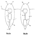
- FIGS 1a and 1b show as cross-sectional views a buoy 1 according to a first embodiment of the present invention.
- the buoy 1 has a main body 5 which accommodates various components including communications equipment, batteries and the like.
- the buoy 1 is shown in Figures 1a and 1b in a floating position, such that the buoy is in a generally upright orientation with an upper end 1a containing an antenna (not shown) being supported about the water line 7.
- the mass 2 comprises heavy payload components such as batteries and optical conversion equipment.
- the mass (dry weight) of the buoy 1 is about 24 Kg and the mass of the moveable mass 2 is about 8 Kg. In a modification of this embodiment, the mass of the buoy is 35 Kg, the moveable mass being about 12 Kg.
- the mass 2 is moveable between (i) a first position (shown in Figure 1b ), in which the centre of mass of the buoy is off-set from its centre of buoyancy, corresponding to a configuration in which the mass 2 is at the lower end 1b of the buoy 1 and (b) a second position in which the centre of mass of the buoy 1 is closer to the centre of buoyancy, corresponding to the case where the mass 2 is moved closer to the centre of the buoy 1.
- the distance of movement of the mass 2 between the first and second positions is about 700mm, which is about 40% of the length of the buoy 1, which acts to shift the.centre of mass of the buoy by over 200mm.
- the centre of buoyancy is positioned just below the centre of the buoy, whilst the centre of mass of the buoy is positioned lower still, thus providing stability in the floating configuration.
- the configuration shown in Figure 1a has the centre of mass of the buoy much closer to the centre of buoyancy (which when the buoy is wholly submerged is roughly at the centre of the buoy), which enables the buoy to be towed underwater in a controlled manner along a desired towing path with a reduced wake/plume, as a result of increased stability.
- the mass 2 may be moved to positions other than the first and second positions. In this embodiment, the mass may be moved to any of an infinite number of positions between the first and second position.
- the buoy 1 has a tether line 3 fixed at its lower end 1b.
- the tether line 3 comprises fibre optic cable and attaches to a submarine vessel (not illustrated) allowing the buoy to be towed and also to facilitate communication between the submarine and the communications buoy 1.
- the buoy is configured in the configuration shown in Figure 1b .
- the moveable mass 2 may be moved up towards the upper end 1a of the buoy 1 in a position ready for the buoy to be retrieved and towed back to the submarine by means rapidly reeling in the tether line 3.
- FIGS 2a and 2b show in cross-section a communications buoy 11 in cross-section according to a second embodiment.
- the buoy 11 includes a moveable mass system and antenna in the same manner as described with reference to the first embodiment, but these are not shown in Figures 2a and 2b .
- the buoy 1 additionally includes an inflatable bladder 18 (shown schematically in Figures 2a and 2b ) accommodated in a chamber 18a at the upper end of the buoy.
- the inflatable bladder 18 has a general shape of a torus, the centre of the torus facilitating connection of an antenna at the upper end 11a of the buoy 11.
- the buoy 11 has a length of about 1.5 metres and a width of about 200 mm.
- the volume of the chamber 18a is about 7 litres.
- the buoy 11 is shown in a configuration suitable for towing, where the moveable mass (not shown) has been moved closer to the centre of buoyancy and the bladder 18 is in a compressed state.
- the chamber 18a surrounding the bladder 18 is filled with water that passes into the chamber 18a by means of a ring of holes (not separately shown) in the main body 15 of the buoy 11 near the interface between the chamber 18a and the lower half of the buoy 11.
- the bladder 18 is sealed but filled with a compressible gas, such as carbon dioxide.
- the centre of mass of the buoy 11 and the centre of buoyancy of the buoy 11 are both positioned at, or very close to, the centre of the buoy 11.
- the chamber 18a is at atmospheric pressure thereby allowing the bladder 18 to expand, water flowing out of the chamber 18a via the holes (not shown) in the main body of the buoy 11.
- the inflated bladder 18 further shifts the centre of mass of the buoy lower down the buoy (i.e. lower in the floating configuration, shown in Figure 2b , than in the towing configuration, shown in Figure 2a , in which the mass of water in the chamber 18a is significantly increased).
- the mass of the buoy 11 is reduced as compared with the towing configuration and the centre of buoyancy of the buoy 11 moves from the centre of the buoy to a position slightly below the centre of the buoy as a result of the upper end of the buoy 11 protruding out of the water.
- the centre of mass on the other hand is displaced by a significant distance, and is positioned significantly lower than the centre of buoyancy as a result of both the moveable mass (not shown) being moved downwards and the upper chamber 18a emptying of water and filling with air.
- the main body 15 of the buoy 11 has a waisted region 19 positioned at the upper end 11a of the buoy.
- the upper end 19a of the waisted region 19 is positioned above the waterline 17 of the buoy 11.
- the waisted region 19 has a shape such that waves and splashing water tend to wash around the buoy 11 beneath the upper end 19a of the waisted region 19, rather than wash over the top surface 11c of the buoy, which might affect the quality of communications facilitated by the antenna at the upper end 11a of the buoy.
- the movable mass is fixed and the motor is removed such that the centre of mass of the buoy may be changed only by means of allowing the bladder to expand and contract as previously described.
- a further additional or alternative modification to the second embodiment would be to control actively the contraction and expansion of the bladder.
- a heater could be provided to heat fluid within a reservoir which would expand to fill and expand the bladder as and when required.
- Pumps or the like could additionally, or alternatively, be used to inflate and/or deflate.
- the shape of the buoy 11 of the second embodiment including the waisted region 19 could by itself provide advantages over conventional shapes of communications buoys, irrespective of whether or not the moveable mass, expandable bladder or other ballasting systems are provided.
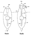
- FIGs 3a and 3b show in cross-section a buoy 31 according to a third embodiment.
- the third embodiment of the invention is similar to the first embodiment, in that a moveable mass (not shown) is provided, which is moveable along a linear screw 34 by means of a motor unit 36.
- the motor unit 36 is also able to extend and retract an antenna 42.
- the antenna 42 has been raised reducing the chance of waves or water splashing over the upper surface 42a of the antenna. Whilst raising the antenna 42 shifts the centre of mass of the buoy closer to the centre of buoyancy, this can be off-set by lowering the moveable mass (not shown) to the lower end of the buoy 31.
- the region between the lower end 42b of the active part of the antenna 42 and the upper end 35a of the rest of the main body 35 of the buoy may be considered as a waisted region 49, such that waves and splashing water have a tendency to wash around the waisted region 49 but_not above it.
- the shape of the main body 35 of the buoy 31 and of the antenna 42 may be adapted to increase the effectiveness of the waisted region 49.
- the waisted region 49 could be shaped such that in the floating communicating configuration shown in Figure 3b the waisted region 49 has an appearance in shape similar to that of the waisted region 19 of the buoy 11 of the second embodiment.
- the motor unit 36 controlling movement of the antenna 42 and the moveable mass may be arranged such that a single motor controls both movements simultaneously. Alternatively, the motor unit 36 may be configured to be able to move independently the antenna 42 and the moveable mass.
Landscapes
- Chemical & Material Sciences (AREA)
- Chemical Kinetics & Catalysis (AREA)
- Engineering & Computer Science (AREA)
- Combustion & Propulsion (AREA)
- Mechanical Engineering (AREA)
- Ocean & Marine Engineering (AREA)
- Details Of Aerials (AREA)
- Other Liquid Machine Or Engine Such As Wave Power Use (AREA)
Abstract
Description
- The present invention concerns a buoy. More particularly, but not exclusively, this invention concerns a tethered communications buoy for use with a submarine vessel. The invention also concerns a method of recovering a tethered buoy.
- The integration of submarine vessels into naval surface operations has been limited by the lack of reliable high-bandwidth data communications systems. Such communications systems should preferably not affect the submarine's primary attribute of stealth, and should preferably be available at speed and depth and without limiting the manoeuvrability or performance of the submarine vessel.
- Proposals for communication systems for a submarine include the use of a tethered communications buoy system. Some of those systems operate by deploying and recovering a communications buoy from a submerged submarine via a tether line, which may for example include a fibre optic cable. Towed buoy systems can generate surface wake potentially risking detection of the location of the submarine. A solution to this problem is to have different modes of operation including a surface mode in which the buoy floats in the water and communicates (in which mode the buoy is not towed by the submarine) and a second travelling mode in which the buoy is recovered by the submarine.
- In a communications buoy system such as that described above, the buoy may be released from the submarine so that it rises to the surface under its own buoyancy, surfacing with low surface disturbance (wake or plume) to reduce the probability of detection. At the surface, the buoy may be engaged in communication during a "communications window". During surface operations, the buoy is allowed to float on the surface whilst a tether line is continually deployed at very low tension from a winch on the submarine. When the communications window is concluded, the buoy system is recovered to the submarine by reversing the winch and reeling the buoy back in so that it travels beneath the water surface. Buoys suitable for this purpose are disclosed in
WO 2005/120942 ,WO 2005/120943 which constitutes the closest prior art, andWO 2007/045864 . - Communications buoys tend to suffer from various problems, some of which will now be described.
- Buoys designed to operate directly below the surface suffer from low data rates. Thus, a communications buoy may include an antenna for receiving/transmitting data, the antenna being positioned at the upper end of the buoy so that the antenna is exposed and is above the water line when the buoy is floating at the water surface. However, in rough waters there may be interruptions to the communications window caused as a result of water washing over the antenna.
- A buoy which is designed so that it floats in a stable and generally upright manner at the surface of the water generally has a shape and/or mass distribution such that it is not very well suited to travelling in a streamlined fashion through water. Also, it may be desirable for the buoy to travel at speed through the water without generating forces which cause the buoy to deviate from a desired path. For example, if the buoy has a tendency to rise in the water when being towed in a generally horizontal direction, the buoy might surface causing highly visible wake and plume on the water surface. On the other hand, if the buoy flies too low in the water (has a tendency to sink when towed at speed), the tether line used to tow the buoy may get too close to the propulsion unit at the rear of the submarine vessel. Various solutions have been proposed to these problems.
-
WO 2005/120942 describes a buoy having a stabilising tail and a yoke connected at one end to a tether line and pivotally connected at the other to the centre of buoyancy of the buoy.WO 2005/120943 discloses a buoy having a tail moveable between a closed position which minimises drag when the buoy travels through water and an open position in which the centre of mass is moved relative to the centre of buoyancy thus facilitating a stable floating configuration. The buoy ofWO 2005/120943 also includes a,pivotally moveable arm for lifting an antenna clear of the water. BothWO 2005/120942 andWO 2005/120943 have the disadvantage of having externally mounted moving parts of a complicated design and which might result in an undesirably large wake/plume at certain speeds/orientations of travel. -
WO 2007/045864 discloses a buoy having fixed hydrodynamic surfaces for increasing the stability of the buoy when towed at certain speeds. The buoy must however travel at certain speeds to be stable in the water. The buoy has a tendency to rise (or sink) to varying degrees in the water, depending on the speed at which it is being towed in the horizontal direction. - The present invention seeks to mitigate the above-mentioned problems. Alternatively or additionally, the present invention seeks to provide an improved buoy.
- According to a first aspect of the present invention, there is provided a buoy having a main body, and a moveable mass positioned inside the main body, the mass being moveable between a first position in which the centre of mass of the buoy is offset from the centre of buoyancy of the buoy and a second position in which the centre of mass is closer to the centre of buoyancy.
- The buoy may thus be used as a communications buoy having two distinct modes of operation: a first mode when the buoy is configured for floating in a generally upright orientation at the water surface in a position ready for communication, when the mass is in the first position to improve stability in the water; and a second mode when the buoy is configured for being towed underwater at speed, when the mass is in the second position to improve towing stability in the water. For example, in the first mode of operation the centre of mass may be positioned significantly lower than the centre of buoyancy thereby urging the buoy into an upright orientation in the water, whereas in the second mode of operation, the centre of mass may be positioned in substantially the same position as the centre of buoyancy. This may thereby allow an elongate buoy to be towed in the water with its long axis substantially aligned with the direction of motion, thereby reducing wake/plume in the water. The buoy may also be configured such that it can be towed in the water at varying speeds without causing any significant change in the tendency of the buoy to rise or sink in the water. This can assist in towing the buoy back to a submarine vessel accurately along a desired path.
- It will be appreciated that the centre of buoyancy of the buoy may not be fixed and may depend on the mass of the buoy and the orientation and position of the buoy in a body of water. Thus, the buoy is preferably configured so that the centre of mass of the buoy may be controllably shifted by a distance greater than the distance by which the centre of buoyancy might change as between the free-floating and submerged states of the buoy. The buoy may be so arranged that the centre of mass of the buoy is controllably moveable by a distance greater than 10% of the length of the buoy, and preferably by a distance greater than 20% of the length of the buoy. The centre of buoyancy of the buoy may be in the region of the centre of the buoy.
- The moveable mass may at least partly be defined by redundant mass. The redundant mass may for example perform no function other than being moveable ballast for the buoy. Alternatively, or additionally, the moveable mass may comprise apparatus arranged to perform a function different from and in addition to providing part of the mass of the moveable mass. For example, the moveable mass may comprise a battery. The moveable mass may be at least partly defined by telecommunications equipment. The majority by mass of the moveable mass is preferably solid. The moveable mass preferably has a mass of greater than 1 Kg. The moveable mass may have a mass of greater than 5 Kg. The moveable mass preferably has a mass greater than 10% of the total mass of the buoy when configured for floating at the water surface. The dry weight of the buoy may be greater than 20 Kg.
- The moveable mass may be arranged for rotational movement between the first and second positions, but in view of the likely shape of the buoy and the desired extreme positions of the moveable mass inside the buoy it may be preferred for the moveable mass to be arranged for linear movement only between the first and second positions. Such linear movement is preferably in a direction along the length of the buoy. The distance between the first and second positions is preferably greater than 20% of the length of the buoy. The distance between the first and second positions is preferably greater than 100mm and may be greater than 250mm.
- The buoy is preferably elongate in shape. The buoy may have a generally round cross-section. The buoy may have a length measured along a longitudinal axis, with the buoy being arranged such that the longitudinal axis is generally vertical when the buoy floats at the water surface. The length of the buoy may be greater than 1m. The length of the buoy may be less than 2m. The ratio of the maximum diameter of the main body of the buoy (i.e. excluding external fins, wings, or the like) to the length of the main body of the buoy is preferably less than 25% and more preferably less than 20%. Thus, the diameter of the main body of the buoy at its widest point is preferably less than 20% of the length of the main body of the buoy. When determining the length or diameter of the main body of the buoy, the dimensions should be measured when the buoy is configured for moving underwater.
- The present invention has particular application in relation to a communications buoy. Thus, the buoy may for example include a communications antenna. The antenna may be mounted at an upper end of the buoy. It will be appreciated that the upper end of the buoy includes more than just the extreme end of the buoy. The antenna may be mounted for linear movement. The antenna may be mounted for movement between a retracted position and an extended position, in which the antenna is raised (or projects) above the main body of the buoy. The buoy may be configured such that when the antenna is in the extended position, there is defined a waisted region between the lower end of the antenna and the upper end of the main body of the buoy. Such a waisted region may assist in reducing water washing over the antenna as is explained in further detail below.
- It will of course be appreciated that the buoy of the present invention may have applications other than as a communications buoy. For example, the buoy could be used as a surveillance buoy. The buoy may include sensing equipment mounted at its upper end (when the buoy is floating at the water surface). Such sensing equipment may include a camera. The equipment mounted at the upper end of the buoy may be removably mounted to allow different equipment to be installed for use in different applications for the buoy. For example, a different antenna may need to be used for different purposes. The buoy including a first items of electronics equipment removably mounted at the upper end of the buoy may form part of a kit of parts including at least one further item of removably mountable electronics equipment for performing a function different from the first item. The first items of electronics equipment may comprise an antenna. The further items of electronics equipment may comprise an antenna.
- The moveable mass may be mounted such that it moves in response to the orientation of, or forces acting on, the buoy. Preferably, however, the buoy includes means for moving the moveable mass, such as a prime mover. The means for moving the moveable mass may, for example, comprise an electric motor. The means for moving the moveable mass may, for example, comprise a lead screw. The means for moving the moveable mass may, for example, comprise a ram. The means for moving the moveable mass may, for example, comprise a solenoid. The means for moving the moveable mass may, for example, comprise a hydraulic component. The means for moving the moveable mass may comprise a control unit mounted in the buoy. The buoy may include electronic equipment, such as a communications antenna, mounted at an upper end of the buoy which is moveable by the same means as provided for moving the moveable mass.
- An upper end of the buoy may have a waisted region. The buoy and the waisted region are preferably so arranged that that the waisted region acts, in use when the buoy is floating at the water surface and electronic equipment is operating at the upper end of the buoy, to increase the protection of such electronic equipment from water washing over the upper surface of the upper end of the buoy. For example, the waisted region may be shaped so as to divert or deflect water that might otherwise simply wash over the top of the buoy. The waisted region may be positioned such that, when the buoy is floating in water, the upper end of the waisted region is above the water line of the buoy.
- The waisted region preferably has a shape that, with increasing distance along the length of the buoy (from bottom to top when in the floating position), decreases from a first diameter to a second diameter and then increases to a third diameter. The second diameter may be the minimum diameter of the waisted region. The third diameter may be the maximum diameter of the portion of the buoy that extends from the second diameter to the uppermost end of the buoy. The first diameter is preferably more than 10% wider than the second diameter and preferably more than 20% wider than the second diameter. The third diameter is preferably more than 10% wider than the second diameter and preferably more than 20% wider than the second diameter. The first diameter may by larger than the third diameter. The first diameter may be equal to the third diameter. The diameter of the buoy preferably varies smoothly with distance along the length of the buoy between the first diameter and the third diameter. The part of the buoy having the smallest radius of curvature (at the external surface of the buoy) when viewed in cross-section along its length may be positioned closer to the third diameter than to the first diameter. There may be a lip in the region of the third diameter which acts to reduce the amount of water than splashes or washes over the uppermost end of the buoy. The buoy may be configured so that the waisted region may be formed or revealed in one mode of operation and otherwise removed, changed or hidden.
- The buoy may include ballast means that is able to displace water so as to change the location of the centre of buoyancy of the buoy. The ballast means may comprise an expandable gas-filled bladder. The ballast means may be positioned at the upper end of the buoy. The ballast means is preferably positioned inside the buoy and is able to cause ingress of water from outside the buoy, as well as egress of water. For example, contraction of a bladder may cause ingress of water, whereas expansion of the bladder causes egress of water. The volume of gas, and/or the pressure of the gas, in the bladder may be passively or may be actively controlled. A means for actively expanding or contracting the bladder may for example be provided in the form of one or more of a heater, a pump, and a valve. The ballast means may be removably mounted. The buoy may form part of a kit of parts including at least one further ballast means of a differing capacity (thereby possibly offering a differing amount of possible change in buoyancy when installed in the buoy). For example, a first ballast means having a first maximum buoyancy may be required for a first application, in which the buoy has a first mass, whereas a second ballast means having a second higher maximum buoyancy may be required for a second application, in which the buoy has a second mass which is higher than the first, for example as a result of carrying different (and heavier) payload.
- The buoy may comprise a connector port for facilitating optical and mechanical connection to a tether line comprising a fibre optic cable. The connector port may be fixedly positioned at the lower end of the buoy.
- The buoy may be a tethered buoy. The buoy may for example be connected to a tether line at a lower end of the buoy. The tether line may comprise fibre optic cable. The tether line may comprise an electric power line, but preferably does not in view of the extra weight and mass that such a power line would contribute to the tether.
- It will be appreciated that the present invention may have application in relation to buoys that are not always tethered or towed. For example, the buoy may be arranged after concluding operations at the water surface to sink without being towed or tethered.
- The advantages of the waisted region of the buoy of the first aspect of the present invention may have application on a buoy in respect of which there is no moveable mass inside the buoy.
- According to a second aspect of the invention, there is provided a communications buoy having a lower end and an upper end, the upper end having a waisted region positioned such that, when the buoy is floating in water in a condition ready to facilitate telecommunication, the upper end of the waisted region is above the water line of the buoy.
- The buoy of the second aspect of the invention may have any of the features of the buoy of the first aspect of the invention. In particular, the waisted region may have any of the features of the waisted region of the first aspect of the invention.
- The present invention also provides a method of using a buoy. The buoy may be tethered by means of a tether line connected at one end to the buoy and at the other end to a submarine vessel. The buoy may additionally, or alternatively, be a buoy according to either the first or second aspects of the invention. The method may include towing the buoy. The method may include causing the buoy to float in a body of water. The method may include changing the position of the centre of mass of the buoy without changing the external shape of the buoy. For example, the centre of mass of the buoy may be moved closer to the centre of buoyancy. A moveably mounted mass may be moved inside the buoy. The method may include withdrawing the buoy from the surface by means of retrieving, for example reeling-in, a tether line attached to the buoy thereby causing the buoy to travel underwater. During performance of the method, the buoyancy of the buoy need not be changed. Alternatively, the method may include a step of changing the buoyancy of the buoy. During the method, water may enter a region in the buoy previously occupied by a fluid having a lower density, thereby changing the buoyancy, the centre of buoyancy and/or the centre of mass.
- During the performance of the method, the buoy may be operated in different modes of operation. For example, there may be a first mode of operation, in which the buoy floats in a generally upright orientation and during which the electronic equipment installed in the upper end of the buoy is operated. For example, the buoy may send and receives data via an antenna at the upper end of the buoy which is held substantially clear of the water. There may be a second mode of operation, during which the buoy is towed underwater via a tether line. The centre of mass of the buoy may be closer to the centre of buoyancy of the buoy during the second mode of operation as compared with the first mode of operation. The second mode of operation may be performed before the first mode. The method may comprise a step of raising an antenna immediately before or during the first mode of operation and may comprise a step of retracting the antenna before commencing the second mode of operation.
- It will of course be appreciated that features described in relation to one aspect of the present invention may be incorporated into other aspects of the present invention. For example, the method of the invention may incorporate any of the features described with reference to the apparatus of the invention and vice versa.
- Embodiments of the present invention will now be described by way of example only with reference to the accompanying schematic drawings of which:
- Figure 1a
- shows a cross-sectional view of a buoy according to a first embodiment of the invention, the buoy being arranged in a towing configuration;
- Figure 1b
- shows a view of the buoy of the first embodiment, but in a floating configuration;
- Figure 2a
- shows a buoy according to a second embodiment, the buoy being arranged in a towing configuration;
- Figure 2b
- shows the buoy of the second embodiment, but in a floating configuration;
- Figure 3a
- shows a buoy according to a third embodiment with an antenna in a retracted position; and
- Figure 3b
- shows the buoy of the third embodiment with the antenna in an extended position.
-
Figures 1a and 1b show as cross-sectional views a buoy 1 according to a first embodiment of the present invention. The buoy 1 has amain body 5 which accommodates various components including communications equipment, batteries and the like. The buoy 1 is shown inFigures 1a and 1b in a floating position, such that the buoy is in a generally upright orientation with anupper end 1a containing an antenna (not shown) being supported about thewater line 7. Inside the buoy 1 there is located amoveable mass 2 which is movable along alongitudinal screw 4 by means of amotor 6. Themass 2 comprises heavy payload components such as batteries and optical conversion equipment. The mass (dry weight) of the buoy 1 is about 24 Kg and the mass of themoveable mass 2 is about 8 Kg. In a modification of this embodiment, the mass of the buoy is 35 Kg, the moveable mass being about 12 Kg. - The
mass 2 is moveable between (i) a first position (shown inFigure 1b ), in which the centre of mass of the buoy is off-set from its centre of buoyancy, corresponding to a configuration in which themass 2 is at thelower end 1b of the buoy 1 and (b) a second position in which the centre of mass of the buoy 1 is closer to the centre of buoyancy, corresponding to the case where themass 2 is moved closer to the centre of the buoy 1. The distance of movement of themass 2 between the first and second positions is about 700mm, which is about 40% of the length of the buoy 1, which acts to shift the.centre of mass of the buoy by over 200mm. In a floating configuration (shown inFigure 1b ), the centre of buoyancy is positioned just below the centre of the buoy, whilst the centre of mass of the buoy is positioned lower still, thus providing stability in the floating configuration. On the other hand, the configuration shown inFigure 1a has the centre of mass of the buoy much closer to the centre of buoyancy (which when the buoy is wholly submerged is roughly at the centre of the buoy), which enables the buoy to be towed underwater in a controlled manner along a desired towing path with a reduced wake/plume, as a result of increased stability. It will of course be appreciated that themass 2 may be moved to positions other than the first and second positions. In this embodiment, the mass may be moved to any of an infinite number of positions between the first and second position. - The buoy 1 has a
tether line 3 fixed at itslower end 1b. Thetether line 3 comprises fibre optic cable and attaches to a submarine vessel (not illustrated) allowing the buoy to be towed and also to facilitate communication between the submarine and the communications buoy 1. During a communications window, during which the communications buoy 1 is engaged with communication, the buoy is configured in the configuration shown inFigure 1b . Once the communications are terminated, themoveable mass 2 may be moved up towards theupper end 1a of the buoy 1 in a position ready for the buoy to be retrieved and towed back to the submarine by means rapidly reeling in thetether line 3. -
Figures 2a and 2b show in cross-section acommunications buoy 11 in cross-section according to a second embodiment. Thebuoy 11 includes a moveable mass system and antenna in the same manner as described with reference to the first embodiment, but these are not shown inFigures 2a and 2b . In the second embodiment, the buoy 1 additionally includes an inflatable bladder 18 (shown schematically inFigures 2a and 2b ) accommodated in achamber 18a at the upper end of the buoy. Theinflatable bladder 18 has a general shape of a torus, the centre of the torus facilitating connection of an antenna at theupper end 11a of thebuoy 11. Thebuoy 11 has a length of about 1.5 metres and a width of about 200 mm. The volume of thechamber 18a is about 7 litres. - In
Figure 2a , thebuoy 11 is shown in a configuration suitable for towing, where the moveable mass (not shown) has been moved closer to the centre of buoyancy and thebladder 18 is in a compressed state. Thechamber 18a surrounding thebladder 18 is filled with water that passes into thechamber 18a by means of a ring of holes (not separately shown) in themain body 15 of thebuoy 11 near the interface between thechamber 18a and the lower half of thebuoy 11. Thebladder 18 is sealed but filled with a compressible gas, such as carbon dioxide. When thebuoy 11 is underwater water pressure acts to compress the gas in thebladder 18 and facilitates ingress of water into thechamber 18a. In the towing configuration the centre of mass of thebuoy 11 and the centre of buoyancy of thebuoy 11 are both positioned at, or very close to, the centre of thebuoy 11. When the buoy is configured in a position ready for floating (as shown inFigure 2b ), in which the movable mass has been lowered towards thelower end 11b of the buoy, thechamber 18a is at atmospheric pressure thereby allowing thebladder 18 to expand, water flowing out of thechamber 18a via the holes (not shown) in the main body of thebuoy 11. Thus, the inflatedbladder 18 further shifts the centre of mass of the buoy lower down the buoy (i.e. lower in the floating configuration, shown inFigure 2b , than in the towing configuration, shown inFigure 2a , in which the mass of water in thechamber 18a is significantly increased). In the floating configuration, the mass of thebuoy 11 is reduced as compared with the towing configuration and the centre of buoyancy of thebuoy 11 moves from the centre of the buoy to a position slightly below the centre of the buoy as a result of the upper end of thebuoy 11 protruding out of the water. The centre of mass on the other hand is displaced by a significant distance, and is positioned significantly lower than the centre of buoyancy as a result of both the moveable mass (not shown) being moved downwards and theupper chamber 18a emptying of water and filling with air. - The
main body 15 of thebuoy 11 has awaisted region 19 positioned at theupper end 11a of the buoy. When thebuoy 11 is floating in the water in a condition ready to facilitate telecommunication (seeFigure 2b ), theupper end 19a of thewaisted region 19 is positioned above thewaterline 17 of thebuoy 11. Thewaisted region 19 has a shape such that waves and splashing water tend to wash around thebuoy 11 beneath theupper end 19a of thewaisted region 19, rather than wash over thetop surface 11c of the buoy, which might affect the quality of communications facilitated by the antenna at theupper end 11a of the buoy. - In a modification of the second embodiment, the movable mass is fixed and the motor is removed such that the centre of mass of the buoy may be changed only by means of allowing the bladder to expand and contract as previously described.
- A further additional or alternative modification to the second embodiment would be to control actively the contraction and expansion of the bladder. For example, a heater could be provided to heat fluid within a reservoir which would expand to fill and expand the bladder as and when required. Pumps or the like could additionally, or alternatively, be used to inflate and/or deflate.
- It will be appreciated, that the shape of the
buoy 11 of the second embodiment including thewaisted region 19 could by itself provide advantages over conventional shapes of communications buoys, irrespective of whether or not the moveable mass, expandable bladder or other ballasting systems are provided. -
Figures 3a and 3b show in cross-section abuoy 31 according to a third embodiment. The third embodiment of the invention is similar to the first embodiment, in that a moveable mass (not shown) is provided, which is moveable along alinear screw 34 by means of amotor unit 36. Themotor unit 36 is also able to extend and retract anantenna 42. Thus, in the position shown inFigure 3b , theantenna 42 has been raised reducing the chance of waves or water splashing over theupper surface 42a of the antenna. Whilst raising theantenna 42 shifts the centre of mass of the buoy closer to the centre of buoyancy, this can be off-set by lowering the moveable mass (not shown) to the lower end of thebuoy 31. Thus, in the configuration shown inFigure 3b the centre of mass of thebuoy 31 is significantly lower than the centre of buoyancy and yet theantenna 42 is raised sufficiently above the waterline for reliable communication, whereas inFigure 3a theantenna 42 is retracted but the moveable mass is moved such that the centre of mass is closer to the centre of buoyancy so that thebuoy 31 may be towed at speed in a stable manner with reduced wake. - In the floating configuration (shown in
Figure 3b ) of thebuoy 31 of the third embodiment, the region between thelower end 42b of the active part of theantenna 42 and theupper end 35a of the rest of themain body 35 of the buoy may be considered as awaisted region 49, such that waves and splashing water have a tendency to wash around thewaisted region 49 but_not above it. It will be appreciated that in this regard, the shape of themain body 35 of thebuoy 31 and of theantenna 42 may be adapted to increase the effectiveness of thewaisted region 49. For example, thewaisted region 49 could be shaped such that in the floating communicating configuration shown inFigure 3b thewaisted region 49 has an appearance in shape similar to that of thewaisted region 19 of thebuoy 11 of the second embodiment. Themotor unit 36 controlling movement of theantenna 42 and the moveable mass may be arranged such that a single motor controls both movements simultaneously. Alternatively, themotor unit 36 may be configured to be able to move independently theantenna 42 and the moveable mass. - Instead of moving the moveable mass and/or antenna by means of a motor and lead screw, other mechanical mechanisms could be employed. For example, hydraulic mechanisms could be employed or a solenoid mechanism could be employed.
- Whilst the present invention has been described and illustrated with reference to particular embodiments, it will be appreciated by those of ordinary skill in the art that the invention lends itself to many different variations not specifically illustrated herein. It will be appreciated that the modifications and variations described above are given by way of example only.
- Where in the foregoing description, integers or elements are mentioned which have known, obvious or foreseeable equivalents, then such equivalents are herein incorporated as if individually set forth. Reference should be made to the claims for determining the true scope of the present invention, which should be construed so as to encompass any such equivalents. It will also be appreciated by the reader that integers or features of the invention that are described as preferable, advantageous, convenient or the like are optional and do not limit the scope of the independent claims. Moreover, it is to be understood that such optional integers or features, whilst of possible benefit in some embodiments of the invention, may not be desirable, and may therefore be absent, in other embodiments.
Claims (15)
- A communications buoy for use in a tethered communications buoy system providing communications function to a submerged submarine vessel, wherein
the buoy has a main body and a communications antenna,
the buoy is operable in a first mode of operation in which the moveable mass is in the first position and in which the buoy floats in a generally upright orientation with an upper end of the buoy being held substantially clear of the water thus enabling the buoy to send and receive data via the communications antenna, and
the buoy is operable in a second mode of operation in which the moveable mass is in the second position and in which the buoy is able to be towed underwater, characterized in that the buoy has a moveable mass positioned inside the main body, the mass being moveable between a first position in which the centre of mass is offset from the centre of buoyancy and a second position in which the centre of mass is closer to the centre of buoyancy. - A communications buoy according to claim 1, wherein the moveable mass is at least partly defined by a battery.
- A communications buoy according to claim 1 or claim 2, wherein the moveable mass is at least partly defined by telecommunications equipment.
- A communications buoy according to any preceding claim, wherein the moveable mass is arranged for linear movement along the length of the buoy.
- A communications buoy according to any preceding claim, wherein the communications antenna is mounted at the upper end of the buoy.
- A communications buoy according to any preceding claim, wherein the communications antenna is linearly moveable from a retracted position to an extended position, in which the antenna is raised above the main body of the buoy.
- A communications buoy according to claim 6, wherein when the antenna is in the extended position, there is defined a waisted region between the lower end of the antenna and the upper end of the main body of the buoy.
- A communications buoy according to any preceding claim, wherein an upper end of the buoy has a waisted region positioned such that, when the buoy is floating in water, the upper end of the waisted region is above the water line of the buoy.
- A communications buoy according to any preceding claim, wherein the buoy includes at an upper end of the buoy an expandable gas-filled bladder that is able to displace water so as to change the location of the centre of mass of the buoy.
- A communications buoy according to claim 9, wherein the bladder is positioned inside the buoy and contraction of the bladder allows ingress of water from outside the buoy, whereas expansion of the bladder allows egress of water.
- A communications buoy according to any preceding claim, wherein the buoy is connected to a tether line at a lower end of the buoy.
- A submarine vessel and a communications buoy, wherein
the communications buoy is a communications buoy according to claim 11,
the tether line is connected at one end to the buoy and at the other end to the submarine vessel,
and the communications buoy provides communications function to the submarine vessel. - A method of recovering a buoy which is floating in a body of water and which is tethered by means of a tether line connected at one end to the buoy and at the other end to a submarine vessel, wherein
the buoy is a communications buoy according to any of claims 1 to 11, and the method comprises the steps of:moving the moveable mass from the first position to the second position, andwithdrawing the buoy from the surface by means of retrieving the tether line to the submarine vessel thereby causing the buoy to travel underwater. - A method according to claim 13, comprising the steps of
operating the buoy in the first mode of operation, thus causing the buoy to float in a generally upright orientation, and causing the buoy to send and receive data via the communications antenna at the upper end of the buoy which is held substantially clear of the water, and
operating the buoy in the second mode of operation during which the buoy is towed underwater via the tether line. - A method according to claim 14, comprising the step of raising the antenna immediately before or during the first mode of operation.
Applications Claiming Priority (2)
| Application Number | Priority Date | Filing Date | Title |
|---|---|---|---|
| GBGB0803834.1A GB0803834D0 (en) | 2008-02-29 | 2008-02-29 | Buoy |
| PCT/GB2009/000567 WO2009106853A2 (en) | 2008-02-29 | 2009-02-27 | Buoy |
Publications (2)
| Publication Number | Publication Date |
|---|---|
| EP2244935A2 EP2244935A2 (en) | 2010-11-03 |
| EP2244935B1 true EP2244935B1 (en) | 2012-06-20 |
Family
ID=39315776
Family Applications (1)
| Application Number | Title | Priority Date | Filing Date |
|---|---|---|---|
| EP09713814A Active EP2244935B1 (en) | 2008-02-29 | 2009-02-27 | Buoy |
Country Status (9)
| Country | Link |
|---|---|
| US (1) | US8512088B2 (en) |
| EP (1) | EP2244935B1 (en) |
| KR (1) | KR101591538B1 (en) |
| AU (1) | AU2009219931B2 (en) |
| CA (1) | CA2713420C (en) |
| ES (1) | ES2388647T3 (en) |
| GB (1) | GB0803834D0 (en) |
| IL (1) | IL207742A (en) |
| WO (1) | WO2009106853A2 (en) |
Cited By (2)
| Publication number | Priority date | Publication date | Assignee | Title |
|---|---|---|---|---|
| CN105438407A (en) * | 2015-12-01 | 2016-03-30 | 中国船舶重工集团公司第七一〇研究所 | Positioning and communication buoy with recoverable bearing force and assembling method |
| RU2735301C1 (en) * | 2019-12-03 | 2020-10-29 | Федеральное государственное казенное военное образовательное учреждение высшего образования "Военный учебно-научный центр Военно-Морского Флота "Военно-морская академия им. Адмирала Флота Советского Союза Н.Г. Кузнецова" | Two-channel emergency beacon for underwater manned apparatus |
Families Citing this family (16)
| Publication number | Priority date | Publication date | Assignee | Title |
|---|---|---|---|---|
| KR101386032B1 (en) * | 2010-03-12 | 2014-04-16 | 한국전자통신연구원 | Emergency position indicating radio beacon terminal, apparatus and method for observing state of operation thereof |
| WO2013181365A1 (en) | 2012-05-31 | 2013-12-05 | Exactech, Inc. | Reverse shoulder humeral adapter trays |
| KR101422714B1 (en) * | 2012-08-08 | 2014-07-24 | 삼성중공업 주식회사 | Solid type ballast device |
| KR101489805B1 (en) * | 2013-07-05 | 2015-02-04 | 한국해양과학기술원 | Apparatus and method for submarine positioning measurements |
| US9061739B1 (en) * | 2014-01-31 | 2015-06-23 | The United States Of America, As Represented By The Secretary Of The Navy | Self-stabilizing buoy and deployment methods |
| US9809281B2 (en) * | 2015-05-18 | 2017-11-07 | Glenn S. Welch | Submersible buoy, inflation control system and kit |
| US10654544B2 (en) | 2017-02-24 | 2020-05-19 | Blue Ocean Gear LLC | Detection of derelict fishing gear |
| USD845809S1 (en) * | 2017-07-05 | 2019-04-16 | Timothy Knapp | Buoy |
| CN108482669B (en) * | 2018-02-23 | 2020-12-29 | 哈尔滨工业大学(威海) | Air and sea amphibious vehicle |
| CN108376824B (en) * | 2018-02-23 | 2019-07-02 | 哈尔滨工业大学(威海) | Floating Antenna Module for Submersible Equipment |
| RU2749618C1 (en) * | 2020-06-08 | 2021-06-16 | Федеральное государственное казенное военное образовательное учреждение высшего образования "Военный учебно-научный центр Военно-Морского Флота "Военно-морская академия имени Адмирала флота Советского Союза Н.Г. Кузнецова" | Drive of the antenna device of the rescue buoy |
| CN113460235B (en) * | 2021-08-12 | 2022-07-05 | 海南师范大学 | Ocean communication buoy |
| ZA202207107B (en) | 2021-08-12 | 2023-02-22 | Univ Hainan Normal | Ocean communication buoy |
| WO2023086526A1 (en) * | 2021-11-10 | 2023-05-19 | Displacement Dynamics, LLC | Systems, devices, and methods for underwater vehicles |
| KR102816963B1 (en) * | 2022-11-28 | 2025-06-16 | 주식회사 비아이씨티 | Search and rescue system for drowning persons based on distress signal relay |
| KR102894723B1 (en) * | 2022-12-21 | 2025-12-02 | 한국로봇융합연구원 | Submersible robot with a single thruster |
Family Cites Families (24)
| Publication number | Priority date | Publication date | Assignee | Title |
|---|---|---|---|---|
| GB114481A (en) | 1917-04-05 | 1918-04-05 | August Gussie Trautman | Improvements in and relating to Submarine Safety Devices. |
| US1556057A (en) * | 1923-06-11 | 1925-10-06 | Harry S Wheller | Textile drier |
| US2224650A (en) * | 1940-04-08 | 1940-12-10 | Holloway Dennis Edgar Joseph | Toy submarine |
| US2586828A (en) * | 1950-01-19 | 1952-02-26 | Royal V Keeran | Radio buoy |
| US3374494A (en) * | 1966-11-16 | 1968-03-26 | William H. Hunley | Variable buoyancy messenger buoy |
| US3972047A (en) * | 1975-08-25 | 1976-07-27 | International Telephone And Telegraph Corporation | Floating cable antenna system |
| US3972046A (en) * | 1975-08-25 | 1976-07-27 | International Telephone And Telegraph Corporation | Antenna arrangement for a submerged submarine |
| JPH0263993A (en) * | 1988-08-30 | 1990-03-05 | Mitsui Eng & Shipbuild Co Ltd | Unmanned diving machine |
| US4964356A (en) * | 1989-06-22 | 1990-10-23 | The United States Of America As Represented By The Secretary Of The Navy | Underwater towed body stabilizing device |
| US5018472A (en) * | 1989-06-22 | 1991-05-28 | The United States Of America As Represented By The Secretary Of The Navy | Horizontally moveable weight stabilizing device |
| US5319376A (en) * | 1992-12-01 | 1994-06-07 | Trw Inc. | Arctic submarine buoy and application methods |
| US5460556A (en) * | 1993-12-30 | 1995-10-24 | Loral Corporation | Variable buoyancy buoy |
| US5748102A (en) * | 1995-09-19 | 1998-05-05 | The United States Of America As Represented By The Secretary Of The Navy | Apparatus for interconnecting an underwater vehicle and a free floating communications pod |
| GB9806340D0 (en) | 1998-03-26 | 1998-05-20 | Weatherburn Robert | Versatile autonomous underwater vehicle |
| US6058874A (en) * | 1998-06-26 | 2000-05-09 | The United States Of America As Represented By The Secretary Of The Navy | Radio frequency communications for underwater vehicle |
| US6183326B1 (en) * | 1999-09-27 | 2001-02-06 | Scientific Solutions, Inc. | Communication buoy with ice penetrating capabilities |
| DE10129696A1 (en) * | 2001-06-22 | 2003-01-02 | Gabler Gmbh Maschbau | Mast device for a submarine |
| US6544088B1 (en) * | 2001-10-10 | 2003-04-08 | The United States Of America As Represented By The Secretary Of The Navy | Self adjusting neutral buoyancy countermeasure and system |
| US6807856B1 (en) * | 2003-05-28 | 2004-10-26 | Douglas C. Webb | Variable buoyancy profiling device |
| KR100531078B1 (en) * | 2003-07-09 | 2005-11-24 | 차봉열 | Marking buoy device using wave-force generation |
| GB2414968B (en) | 2004-06-07 | 2008-10-22 | Thales Uk Plc | Buoyant device |
| GB2414976B (en) | 2004-06-07 | 2008-03-05 | Thales Uk Plc | Towing device adapted to stabilise a towed body |
| GB2431380A (en) * | 2005-10-18 | 2007-04-25 | Ultra Electronics Ltd | A buoy having fixed hydrodynamic surfaces |
| US7559288B2 (en) * | 2007-07-30 | 2009-07-14 | The United States Of America As Represented By The Secretary Of The Navy | Recoverable optical fiber tethered buoy assembly |
-
2008
- 2008-02-29 GB GBGB0803834.1A patent/GB0803834D0/en not_active Ceased
-
2009
- 2009-02-27 AU AU2009219931A patent/AU2009219931B2/en not_active Ceased
- 2009-02-27 US US12/920,259 patent/US8512088B2/en not_active Expired - Fee Related
- 2009-02-27 WO PCT/GB2009/000567 patent/WO2009106853A2/en not_active Ceased
- 2009-02-27 ES ES09713814T patent/ES2388647T3/en active Active
- 2009-02-27 EP EP09713814A patent/EP2244935B1/en active Active
- 2009-02-27 CA CA2713420A patent/CA2713420C/en active Active
- 2009-02-27 KR KR1020107019449A patent/KR101591538B1/en not_active Expired - Fee Related
-
2010
- 2010-08-22 IL IL207742A patent/IL207742A/en active IP Right Grant
Cited By (3)
| Publication number | Priority date | Publication date | Assignee | Title |
|---|---|---|---|---|
| CN105438407A (en) * | 2015-12-01 | 2016-03-30 | 中国船舶重工集团公司第七一〇研究所 | Positioning and communication buoy with recoverable bearing force and assembling method |
| CN105438407B (en) * | 2015-12-01 | 2017-08-25 | 中国船舶重工集团公司第七一〇研究所 | A kind of recyclable positioning of load and communication buoy and assemble method |
| RU2735301C1 (en) * | 2019-12-03 | 2020-10-29 | Федеральное государственное казенное военное образовательное учреждение высшего образования "Военный учебно-научный центр Военно-Морского Флота "Военно-морская академия им. Адмирала Флота Советского Союза Н.Г. Кузнецова" | Two-channel emergency beacon for underwater manned apparatus |
Also Published As
| Publication number | Publication date |
|---|---|
| GB0803834D0 (en) | 2008-04-09 |
| KR101591538B1 (en) | 2016-02-18 |
| EP2244935A2 (en) | 2010-11-03 |
| IL207742A0 (en) | 2010-12-30 |
| US8512088B2 (en) | 2013-08-20 |
| CA2713420A1 (en) | 2009-09-03 |
| WO2009106853A3 (en) | 2010-06-24 |
| AU2009219931A1 (en) | 2009-09-03 |
| CA2713420C (en) | 2016-02-02 |
| IL207742A (en) | 2014-06-30 |
| ES2388647T3 (en) | 2012-10-17 |
| AU2009219931B2 (en) | 2013-09-12 |
| WO2009106853A2 (en) | 2009-09-03 |
| US20110000417A1 (en) | 2011-01-06 |
| KR20100120675A (en) | 2010-11-16 |
Similar Documents
| Publication | Publication Date | Title |
|---|---|---|
| US8512088B2 (en) | Buoy | |
| EP2657125B1 (en) | Underwater mobile apparatus and moving method thereof | |
| US20050279272A1 (en) | Mast device for a submarine | |
| AU2006303131B2 (en) | Buoy | |
| JP7259153B2 (en) | mooring buoy | |
| EP1765665B1 (en) | Buoyant device | |
| CN113581431B (en) | Floating and diving regulator for regulating gravity center and specific gravity and underwater smart roaming craft | |
| CN115515817A (en) | Device and method for inductively transmitting electrical energy to a watercraft, and charging system | |
| CN208774968U (en) | A kind of communication buoy and underwater winch detection device | |
| US20120186507A1 (en) | Towable buoy | |
| CN114104199B (en) | A low-power self-heave submersible based on glider and its working method | |
| CN117429591A (en) | An underwater expandable active sonar vehicle | |
| CN121573117A (en) | A mother ship for launching and recovering unmanned equipment at sea | |
| US20150204466A1 (en) | Underwater utility line | |
| CA2292268A1 (en) | Boat ballast system | |
| WO2023208936A1 (en) | Stabilisation system | |
| JPH0672381A (en) | Lifting device for underwater objects |
Legal Events
| Date | Code | Title | Description |
|---|---|---|---|
| PUAI | Public reference made under article 153(3) epc to a published international application that has entered the european phase |
Free format text: ORIGINAL CODE: 0009012 |
|
| 17P | Request for examination filed |
Effective date: 20100809 |
|
| AK | Designated contracting states |
Kind code of ref document: A2 Designated state(s): AT BE BG CH CY CZ DE DK EE ES FI FR GB GR HR HU IE IS IT LI LT LU LV MC MK MT NL NO PL PT RO SE SI SK TR |
|
| AX | Request for extension of the european patent |
Extension state: AL BA RS |
|
| DAX | Request for extension of the european patent (deleted) | ||
| GRAP | Despatch of communication of intention to grant a patent |
Free format text: ORIGINAL CODE: EPIDOSNIGR1 |
|
| GRAS | Grant fee paid |
Free format text: ORIGINAL CODE: EPIDOSNIGR3 |
|
| GRAA | (expected) grant |
Free format text: ORIGINAL CODE: 0009210 |
|
| AK | Designated contracting states |
Kind code of ref document: B1 Designated state(s): AT BE BG CH CY CZ DE DK EE ES FI FR GB GR HR HU IE IS IT LI LT LU LV MC MK MT NL NO PL PT RO SE SI SK TR |
|
| REG | Reference to a national code |
Ref country code: GB Ref legal event code: FG4D |
|
| REG | Reference to a national code |
Ref country code: CH Ref legal event code: EP |
|
| REG | Reference to a national code |
Ref country code: AT Ref legal event code: REF Ref document number: 562912 Country of ref document: AT Kind code of ref document: T Effective date: 20120715 |
|
| REG | Reference to a national code |
Ref country code: IE Ref legal event code: FG4D |
|
| REG | Reference to a national code |
Ref country code: DE Ref legal event code: R096 Ref document number: 602009007724 Country of ref document: DE Effective date: 20120816 |
|
| REG | Reference to a national code |
Ref country code: SE Ref legal event code: TRGR |
|
| REG | Reference to a national code |
Ref country code: ES Ref legal event code: FG2A Ref document number: 2388647 Country of ref document: ES Kind code of ref document: T3 Effective date: 20121017 |
|
| PG25 | Lapsed in a contracting state [announced via postgrant information from national office to epo] |
Ref country code: FI Free format text: LAPSE BECAUSE OF FAILURE TO SUBMIT A TRANSLATION OF THE DESCRIPTION OR TO PAY THE FEE WITHIN THE PRESCRIBED TIME-LIMIT Effective date: 20120620 Ref country code: NO Free format text: LAPSE BECAUSE OF FAILURE TO SUBMIT A TRANSLATION OF THE DESCRIPTION OR TO PAY THE FEE WITHIN THE PRESCRIBED TIME-LIMIT Effective date: 20120920 Ref country code: LT Free format text: LAPSE BECAUSE OF FAILURE TO SUBMIT A TRANSLATION OF THE DESCRIPTION OR TO PAY THE FEE WITHIN THE PRESCRIBED TIME-LIMIT Effective date: 20120620 |
|
| REG | Reference to a national code |
Ref country code: NL Ref legal event code: VDEP Effective date: 20120620 |
|
| REG | Reference to a national code |
Ref country code: AT Ref legal event code: MK05 Ref document number: 562912 Country of ref document: AT Kind code of ref document: T Effective date: 20120620 |
|
| REG | Reference to a national code |
Ref country code: LT Ref legal event code: MG4D Effective date: 20120620 |
|
| PG25 | Lapsed in a contracting state [announced via postgrant information from national office to epo] |
Ref country code: GR Free format text: LAPSE BECAUSE OF FAILURE TO SUBMIT A TRANSLATION OF THE DESCRIPTION OR TO PAY THE FEE WITHIN THE PRESCRIBED TIME-LIMIT Effective date: 20120921 Ref country code: LV Free format text: LAPSE BECAUSE OF FAILURE TO SUBMIT A TRANSLATION OF THE DESCRIPTION OR TO PAY THE FEE WITHIN THE PRESCRIBED TIME-LIMIT Effective date: 20120620 Ref country code: SI Free format text: LAPSE BECAUSE OF FAILURE TO SUBMIT A TRANSLATION OF THE DESCRIPTION OR TO PAY THE FEE WITHIN THE PRESCRIBED TIME-LIMIT Effective date: 20120620 Ref country code: HR Free format text: LAPSE BECAUSE OF FAILURE TO SUBMIT A TRANSLATION OF THE DESCRIPTION OR TO PAY THE FEE WITHIN THE PRESCRIBED TIME-LIMIT Effective date: 20120620 |
|
| PG25 | Lapsed in a contracting state [announced via postgrant information from national office to epo] |
Ref country code: SK Free format text: LAPSE BECAUSE OF FAILURE TO SUBMIT A TRANSLATION OF THE DESCRIPTION OR TO PAY THE FEE WITHIN THE PRESCRIBED TIME-LIMIT Effective date: 20120620 Ref country code: EE Free format text: LAPSE BECAUSE OF FAILURE TO SUBMIT A TRANSLATION OF THE DESCRIPTION OR TO PAY THE FEE WITHIN THE PRESCRIBED TIME-LIMIT Effective date: 20120620 Ref country code: CY Free format text: LAPSE BECAUSE OF FAILURE TO SUBMIT A TRANSLATION OF THE DESCRIPTION OR TO PAY THE FEE WITHIN THE PRESCRIBED TIME-LIMIT Effective date: 20120620 Ref country code: IS Free format text: LAPSE BECAUSE OF FAILURE TO SUBMIT A TRANSLATION OF THE DESCRIPTION OR TO PAY THE FEE WITHIN THE PRESCRIBED TIME-LIMIT Effective date: 20121020 Ref country code: BE Free format text: LAPSE BECAUSE OF FAILURE TO SUBMIT A TRANSLATION OF THE DESCRIPTION OR TO PAY THE FEE WITHIN THE PRESCRIBED TIME-LIMIT Effective date: 20120620 Ref country code: RO Free format text: LAPSE BECAUSE OF FAILURE TO SUBMIT A TRANSLATION OF THE DESCRIPTION OR TO PAY THE FEE WITHIN THE PRESCRIBED TIME-LIMIT Effective date: 20120620 Ref country code: CZ Free format text: LAPSE BECAUSE OF FAILURE TO SUBMIT A TRANSLATION OF THE DESCRIPTION OR TO PAY THE FEE WITHIN THE PRESCRIBED TIME-LIMIT Effective date: 20120620 Ref country code: AT Free format text: LAPSE BECAUSE OF FAILURE TO SUBMIT A TRANSLATION OF THE DESCRIPTION OR TO PAY THE FEE WITHIN THE PRESCRIBED TIME-LIMIT Effective date: 20120620 |
|
| PG25 | Lapsed in a contracting state [announced via postgrant information from national office to epo] |
Ref country code: IT Free format text: LAPSE BECAUSE OF FAILURE TO SUBMIT A TRANSLATION OF THE DESCRIPTION OR TO PAY THE FEE WITHIN THE PRESCRIBED TIME-LIMIT Effective date: 20120620 Ref country code: PT Free format text: LAPSE BECAUSE OF FAILURE TO SUBMIT A TRANSLATION OF THE DESCRIPTION OR TO PAY THE FEE WITHIN THE PRESCRIBED TIME-LIMIT Effective date: 20121022 Ref country code: PL Free format text: LAPSE BECAUSE OF FAILURE TO SUBMIT A TRANSLATION OF THE DESCRIPTION OR TO PAY THE FEE WITHIN THE PRESCRIBED TIME-LIMIT Effective date: 20120620 |
|
| PG25 | Lapsed in a contracting state [announced via postgrant information from national office to epo] |
Ref country code: NL Free format text: LAPSE BECAUSE OF FAILURE TO SUBMIT A TRANSLATION OF THE DESCRIPTION OR TO PAY THE FEE WITHIN THE PRESCRIBED TIME-LIMIT Effective date: 20120620 |
|
| PLBE | No opposition filed within time limit |
Free format text: ORIGINAL CODE: 0009261 |
|
| STAA | Information on the status of an ep patent application or granted ep patent |
Free format text: STATUS: NO OPPOSITION FILED WITHIN TIME LIMIT |
|
| PG25 | Lapsed in a contracting state [announced via postgrant information from national office to epo] |
Ref country code: DK Free format text: LAPSE BECAUSE OF FAILURE TO SUBMIT A TRANSLATION OF THE DESCRIPTION OR TO PAY THE FEE WITHIN THE PRESCRIBED TIME-LIMIT Effective date: 20120620 |
|
| 26N | No opposition filed |
Effective date: 20130321 |
|
| REG | Reference to a national code |
Ref country code: DE Ref legal event code: R097 Ref document number: 602009007724 Country of ref document: DE Effective date: 20130321 |
|
| PG25 | Lapsed in a contracting state [announced via postgrant information from national office to epo] |
Ref country code: BG Free format text: LAPSE BECAUSE OF FAILURE TO SUBMIT A TRANSLATION OF THE DESCRIPTION OR TO PAY THE FEE WITHIN THE PRESCRIBED TIME-LIMIT Effective date: 20120920 |
|
| PG25 | Lapsed in a contracting state [announced via postgrant information from national office to epo] |
Ref country code: MC Free format text: LAPSE BECAUSE OF NON-PAYMENT OF DUE FEES Effective date: 20130228 |
|
| REG | Reference to a national code |
Ref country code: CH Ref legal event code: PL |
|
| PG25 | Lapsed in a contracting state [announced via postgrant information from national office to epo] |
Ref country code: CH Free format text: LAPSE BECAUSE OF NON-PAYMENT OF DUE FEES Effective date: 20130228 Ref country code: LI Free format text: LAPSE BECAUSE OF NON-PAYMENT OF DUE FEES Effective date: 20130228 |
|
| REG | Reference to a national code |
Ref country code: IE Ref legal event code: MM4A |
|
| PG25 | Lapsed in a contracting state [announced via postgrant information from national office to epo] |
Ref country code: IE Free format text: LAPSE BECAUSE OF NON-PAYMENT OF DUE FEES Effective date: 20130227 |
|
| PG25 | Lapsed in a contracting state [announced via postgrant information from national office to epo] |
Ref country code: MT Free format text: LAPSE BECAUSE OF FAILURE TO SUBMIT A TRANSLATION OF THE DESCRIPTION OR TO PAY THE FEE WITHIN THE PRESCRIBED TIME-LIMIT Effective date: 20120620 |
|
| PG25 | Lapsed in a contracting state [announced via postgrant information from national office to epo] |
Ref country code: TR Free format text: LAPSE BECAUSE OF FAILURE TO SUBMIT A TRANSLATION OF THE DESCRIPTION OR TO PAY THE FEE WITHIN THE PRESCRIBED TIME-LIMIT Effective date: 20120620 |
|
| PG25 | Lapsed in a contracting state [announced via postgrant information from national office to epo] |
Ref country code: MK Free format text: LAPSE BECAUSE OF FAILURE TO SUBMIT A TRANSLATION OF THE DESCRIPTION OR TO PAY THE FEE WITHIN THE PRESCRIBED TIME-LIMIT Effective date: 20120620 Ref country code: LU Free format text: LAPSE BECAUSE OF NON-PAYMENT OF DUE FEES Effective date: 20130227 Ref country code: HU Free format text: LAPSE BECAUSE OF FAILURE TO SUBMIT A TRANSLATION OF THE DESCRIPTION OR TO PAY THE FEE WITHIN THE PRESCRIBED TIME-LIMIT; INVALID AB INITIO Effective date: 20090227 |
|
| REG | Reference to a national code |
Ref country code: FR Ref legal event code: PLFP Year of fee payment: 8 |
|
| REG | Reference to a national code |
Ref country code: GB Ref legal event code: 732E Free format text: REGISTERED BETWEEN 20160901 AND 20160907 |
|
| REG | Reference to a national code |
Ref country code: DE Ref legal event code: R081 Ref document number: 602009007724 Country of ref document: DE Owner name: BABCOCK IP MANAGEMENT (NUMBER ONE) LTD., GB Free format text: FORMER OWNER: BABCOCK INTEGRATED TECHNOLOGY LIMITED, LONDON, GB Ref country code: DE Ref legal event code: R082 Ref document number: 602009007724 Country of ref document: DE Representative=s name: SCHMITT-NILSON SCHRAUD WAIBEL WOHLFROM PATENTA, DE Ref country code: DE Ref legal event code: R082 Ref document number: 602009007724 Country of ref document: DE Representative=s name: KLUNKER, SCHMITT-NILSON, HIRSCH, DE |
|
| REG | Reference to a national code |
Ref country code: FR Ref legal event code: PLFP Year of fee payment: 9 |
|
| REG | Reference to a national code |
Ref country code: DE Ref legal event code: R082 Ref document number: 602009007724 Country of ref document: DE Representative=s name: SCHMITT-NILSON SCHRAUD WAIBEL WOHLFROM PATENTA, DE |
|
| REG | Reference to a national code |
Ref country code: FR Ref legal event code: TP Owner name: BABCOCK IP MANAGEMENT (NUMBER ONE) LIMITED, GB Effective date: 20170822 |
|
| REG | Reference to a national code |
Ref country code: FR Ref legal event code: PLFP Year of fee payment: 10 |
|
| PGFP | Annual fee paid to national office [announced via postgrant information from national office to epo] |
Ref country code: ES Payment date: 20240305 Year of fee payment: 16 |
|
| PGFP | Annual fee paid to national office [announced via postgrant information from national office to epo] |
Ref country code: DE Payment date: 20240130 Year of fee payment: 16 |
|
| PGFP | Annual fee paid to national office [announced via postgrant information from national office to epo] |
Ref country code: SE Payment date: 20240130 Year of fee payment: 16 Ref country code: FR Payment date: 20240213 Year of fee payment: 16 |
|
| REG | Reference to a national code |
Ref country code: DE Ref legal event code: R119 Ref document number: 602009007724 Country of ref document: DE |
|
| REG | Reference to a national code |
Ref country code: SE Ref legal event code: EUG |
|
| PG25 | Lapsed in a contracting state [announced via postgrant information from national office to epo] |
Ref country code: DE Free format text: LAPSE BECAUSE OF NON-PAYMENT OF DUE FEES Effective date: 20250902 |
|
| PG25 | Lapsed in a contracting state [announced via postgrant information from national office to epo] |
Ref country code: FR Free format text: LAPSE BECAUSE OF NON-PAYMENT OF DUE FEES Effective date: 20250228 |
|
| REG | Reference to a national code |
Ref country code: ES Ref legal event code: FD2A Effective date: 20260407 |
|
| PGFP | Annual fee paid to national office [announced via postgrant information from national office to epo] |
Ref country code: GB Payment date: 20260216 Year of fee payment: 18 |
|
| PG25 | Lapsed in a contracting state [announced via postgrant information from national office to epo] |
Ref country code: ES Free format text: LAPSE BECAUSE OF NON-PAYMENT OF DUE FEES Effective date: 20250228 |