EP2244251A1 - Transmitted sound control apparatus - Google Patents
Transmitted sound control apparatus Download PDFInfo
- Publication number
- EP2244251A1 EP2244251A1 EP10004182A EP10004182A EP2244251A1 EP 2244251 A1 EP2244251 A1 EP 2244251A1 EP 10004182 A EP10004182 A EP 10004182A EP 10004182 A EP10004182 A EP 10004182A EP 2244251 A1 EP2244251 A1 EP 2244251A1
- Authority
- EP
- European Patent Office
- Prior art keywords
- sound
- control apparatus
- insulating plate
- transmitted
- sound insulating
- Prior art date
- Legal status (The legal status is an assumption and is not a legal conclusion. Google has not performed a legal analysis and makes no representation as to the accuracy of the status listed.)
- Ceased
Links
- 238000000638 solvent extraction Methods 0.000 claims abstract description 7
- 230000007246 mechanism Effects 0.000 claims description 22
- 230000008859 change Effects 0.000 claims description 10
- 230000002093 peripheral effect Effects 0.000 claims description 7
- 238000013519 translation Methods 0.000 claims description 6
- 238000010276 construction Methods 0.000 abstract description 17
- 230000000644 propagated effect Effects 0.000 abstract description 9
- 238000003475 lamination Methods 0.000 abstract description 6
- 230000004044 response Effects 0.000 description 9
- 230000007423 decrease Effects 0.000 description 8
- 238000012986 modification Methods 0.000 description 5
- 230000004048 modification Effects 0.000 description 5
- 230000003247 decreasing effect Effects 0.000 description 4
- 238000010586 diagram Methods 0.000 description 4
- 238000000034 method Methods 0.000 description 4
- 238000012856 packing Methods 0.000 description 4
- 239000000463 material Substances 0.000 description 3
- 229920006267 polyester film Polymers 0.000 description 3
- 230000005236 sound signal Effects 0.000 description 3
- 238000012360 testing method Methods 0.000 description 3
- 238000012546 transfer Methods 0.000 description 3
- CURLTUGMZLYLDI-UHFFFAOYSA-N Carbon dioxide Chemical compound O=C=O CURLTUGMZLYLDI-UHFFFAOYSA-N 0.000 description 2
- -1 acryl Chemical group 0.000 description 2
- 238000001514 detection method Methods 0.000 description 2
- 239000011491 glass wool Substances 0.000 description 2
- 239000011148 porous material Substances 0.000 description 2
- 239000011347 resin Substances 0.000 description 2
- 229920005989 resin Polymers 0.000 description 2
- 239000011358 absorbing material Substances 0.000 description 1
- 239000003570 air Substances 0.000 description 1
- 230000002238 attenuated effect Effects 0.000 description 1
- 230000005540 biological transmission Effects 0.000 description 1
- 229910002092 carbon dioxide Inorganic materials 0.000 description 1
- 239000001569 carbon dioxide Substances 0.000 description 1
- 230000008602 contraction Effects 0.000 description 1
- 239000000446 fuel Substances 0.000 description 1
- 238000012545 processing Methods 0.000 description 1
- 239000004576 sand Substances 0.000 description 1
- 229910001285 shape-memory alloy Inorganic materials 0.000 description 1
- XLYOFNOQVPJJNP-UHFFFAOYSA-N water Substances O XLYOFNOQVPJJNP-UHFFFAOYSA-N 0.000 description 1
Images


Classifications
-
- G—PHYSICS
- G10—MUSICAL INSTRUMENTS; ACOUSTICS
- G10K—SOUND-PRODUCING DEVICES; METHODS OR DEVICES FOR PROTECTING AGAINST, OR FOR DAMPING, NOISE OR OTHER ACOUSTIC WAVES IN GENERAL; ACOUSTICS NOT OTHERWISE PROVIDED FOR
- G10K11/00—Methods or devices for transmitting, conducting or directing sound in general; Methods or devices for protecting against, or for damping, noise or other acoustic waves in general
- G10K11/18—Methods or devices for transmitting, conducting or directing sound
- G10K11/22—Methods or devices for transmitting, conducting or directing sound for conducting sound through hollow pipes, e.g. speaking tubes
-
- B—PERFORMING OPERATIONS; TRANSPORTING
- B60—VEHICLES IN GENERAL
- B60R—VEHICLES, VEHICLE FITTINGS, OR VEHICLE PARTS, NOT OTHERWISE PROVIDED FOR
- B60R13/00—Elements for body-finishing, identifying, or decorating; Arrangements or adaptations for advertising purposes
- B60R13/08—Insulating elements, e.g. for sound insulation
Definitions
- the present invention relates a technique for controlling an acoustic quality of sound coming from outside a room (or outside a vehicle) into the room (or vehicle).
- Japanese Patent No. 2755094 discloses a technique for alleviating a cooped-up feeling which may be felt by a person present in a sound-insulated, soundproof chamber.
- the soundproof chamber is provided within a room, and one or both of an outdoor microphone provided outside the room and an indoor microphone provided outside the soundproof chamber within the room are selected, through operation on an operation section, so that sound signals picked up by the selected microphone or microphones are audibly reproduced or sounded via a speaker provided within the soundproof chamber.
- the person in the room may feel a cooped-up feeling if sound propagated from outside the room (i.e., outdoor sound) is completely blocked by walls etc.
- the person may feel noisy if sound from outside the room is heard with an original (i.e., unchanged) acoustic quality.
- a sound signal processing system including a microphone and a speaker
- an outdoor sound can be made to be heard as sound of an acoustic quality suiting a preference of the person; in this case, however, a power supply is required, so that a necessary apparatus construction would increase in size.
- the present invention provides an improved transmitted sound control apparatus which includes a sound insulating plate supported at an interval from a boundary surface having an opening portion and in opposed relation to the opening.
- sound produced outside the boundary surface transmits through the opening portion to propagate to inside of the boundary surface.
- the sound i.e., transmitted sound
- the thus-reflected sound is diffracted via side edge portions of the interval, defined between the sound insulating plate and the boundary surface, rearwardly (i.e., rearwardly assuming that the sound reflected direction is referred to as forwardly) to behind the sound insulating plate and propagate to the human listener.
- components of various frequency bands of the sound having transmitted through the opening portion to propagate to inside of the boundary surface, are changed when it is reflected from the sound insulating plate and when it is diffracted rearwardly to behind the sound insulating plate, so that the sound can be made to be heard as sound having frequency characteristics desired by the human listener.
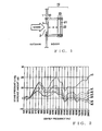
- Fig. 1 is a diagram showing an example general setup of a first embodiment of a transmitted sound control apparatus 10 of the present invention.
- the transmitted sound control apparatus 10 of Fig. 1 includes an opening portion 2 formed in a wall 1 that functions as a boundary surface partitioning between an outside and an inside of the room, and it is arranged to allow sound, propagated from the outside of the room into the room, to be heard by a human listener as sound having adjusted frequency characteristics.
- the transmitted sound control apparatus 10 also includes a film 3, a sound insulating plate 20, and an appropriate number of rod-shaped support members 30.
- the sound insulating plate 20, which is disposed in the inside of the room, comprises a lamination of a resin-made sound reflecting plate 21 and a sound absorbing member 22.
- the sound reflecting plate 21 is made by forming a material (e.g., acryl resin), having a sound insulting performance or capability (or area density) equal to or less than that of the wall 1, into a plate shape.
- the sound absorbing member 22 is made of a porous material, such as glass wool.
- the support members 30 together constitute a support mechanism 30 that supports the sound insulating plate 20 in such a manner that a surface of the sound absorbing member 22 is opposed to the opening portion 2 with an interval d defined between the sound insulating plate 20 and the wall 1.
- the sound insulating plate 20 is of a rectangular shape, it may be fixed by respective one ends of four support members 30 being passed through portions of the sound insulating plate 20 near the four corners of the plate 20 and the respective other ends of the four support members 30 being passed through or embedded in the wall 1.
- four bolts may be used as the four support members 30 each sandwiching the sound insulating plate 20 with two nuts threaded on the bolt. Such an arrangement allows the distance d between the sound insulating plate 20 and the wall 1 to be adjusted in response to manipulation of the nuts.
- the transmitted sound control apparatus 10 A sound produced outside the room propagates or transmits through the film 3, closing the opening portion 2, into the room. Then, the sound transmitted through the film 3 is reflected from the sound reflecting plate 21 of the sound insulating plate 20, and the thus-reflected sound is difracted via side edge portions of the interval d, defined between the sound reflecting plate 21 and the wall 1, rearward to behind the reflecting plate 21 to propagate to or reach the human listener.
- components of various frequency bands of the sound produced outside the room are changed when the sound transmits through the film 3, when it is reflected from the sound reflecting plate 21 and when it is diffracted to behind the reflecting plate 21, so that the sound can be made to be heard by a human listener as sound having desired frequency characteristics.
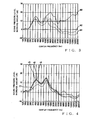
- the inventor of the present invention conducted the following test.
- the inventor set different Conditions 1 - 13 that differ in presence/absence (i.e., provided/not-provided) of the opening 2 in the wall 1, presence/absence of closure, by the film 3, of the opening portion 2, presence/absence (i.e., provided/not-provided) of the sound insulating plate 20, thickness of the film 3, distance between the opening portion 2 and the sound insulating plate 20 and size of the sound insulating plate 20, as shown in a table below.
- the inventor caused a pink noise sound signal to be generated as sound outside the wall 1; picked up the sound via a microphone placed within the room at a distance of 50 cm from the wall 1; and determined a sound pressure level of every one-third octave of the sound picked up by the microphone under each of Conditions 1 - 13.
- the opening portion 2 formed in the wall 1 comprises three opening portions each having a diameter of 40 mm and disposed in a row at a 60-mm pitch.
- sound pressure level increase amounts (dB)
- a graph curve a0 indicates a sound pressure level increase amount vs. frequency characteristic in the case where the opening portion 2 in the wall 1 is not closed with the film 3.
- the graph curves a1, a2, a3, a4, a5 and a6 indicate sound pressure level increase amount vs. frequency characteristics in the case where the opening portion 2 in the wall 1 is closed with films 3 of different thicknesses. From the graph curves a0, a1, a2, a3, a4, a5 and a6, it can been seen that sound pressure level attenuation amounts in frequency bands higher than about 315 Hz in the case where the opening portion 2 is closed with the film 3 are greater than those in the case where the opening portion 2 is not closed with the film 3.
- a graph curve b0 indicates a sound pressure level increase amount vs. frequency characteristic in the case where the opening portion 2 in the wall 1 is not closed with the film 3.
- graph curves b1 and b2 indicate sound pressure level increase amount vs. frequency characteristics in the case where the size of the sound insulating plate 20 opposed to the opening portion 2 was differentiated with the thickness of the film 3 closing the opening portion 2 in the wall 1 kept the same.
- sound pressure level increase amounts in frequency bands higher than 1,000 Hz of a graph curve b1 are much lower than those in frequency bands higher than 1,000 Hz of the graph curve b0.
- Graph curves c1, c2, c3 and c4 of Fig. 4 indicate sound pressure level increase amount vs. frequency characteristics in the case where the distance between the wall 1 and the sound insulating plate 20 was changed in steps of 15 mm from 0 mm to 45 with the thickness of the film 3, closing the opening portion 2 in the wall 1, kept the same. Focusing on frequency bands higher than 250 Hz but lower than 1,000 Hz in Fig.
- the sound pressure level increase amounts in the predetermined frequency bands higher than 250 Hz but lower than 1,000 Hz can be decreased by decreasing the distance d between the wall 1 and the sound insulating plate 20 to 0 mm from a predetermined value greater than 0 mm (value in the range of 15 mm - 45 mm in the instant embodiment). Further, the sound pressure level increase amounts in the predetermined frequency bands higher than 250 Hz but lower than 1,000 Hz can be increased by increasing the distance d between the wall 1 and the sound insulating plate 20 from 0 mm to a desired value (15 mm in the instant embodiment).
- a transmitted sound control apparatus 10A as a specific applied example of the transmitted sound control apparatus 10 of Fig. 1 , which includes a support mechanism for supporting the sound insulating plate 20 in such a manner as to permit a change in a positional relationship of the sound insulating plate 20 relative to the opening portion 2.
- Fig. 5 is a block diagram showing a general setup of the transmitted sound control apparatus 10A constructed as a specific applied example of the apparatus 10 of Fig. 1
- Fig. 6 is a sectional view of the transmitted sound control apparatus 10A taken along the A - A' line of Fig. 5 , i.e. as viewed in a direction from the interior of the room toward the wall 1.
- the transmitted sound control apparatus 10A as shown in Fig.
- the wall 1 has three opening portions 2L, 2C and 2R formed therein in a horizontal (i.e., left-right) row, and it also has three films 3L, 3C and 3R attached to or provided on the wall 1 in such a manner as to close or cover respective ones of the three opening portions 2L, 2C and 2R.
- the transmitted sound control apparatus 10A also includes the support mechanism 35 having an actuator 41 that translates a box-shaped casing member 31 along a translation shaft extending normally to the surface of the wall 1.
- Another actuator 40 is fixed within the casing member 31.
- This actuator 40 has a rotation shaft 23 projecting from the casing member 31 toward the wall 1 at right angles thereto, and this rotation shaft 23 is rotatable by the actuator 40.
- the sound insulating plate 20 is fixed to the distal end of the rotation shaft 23 of the actuator 40 to lie parallel to the surface of the wall 1.
- the rotation shaft 23 extends normally to the surface of the sound insulating plate 20. As shown in Fig.
- the sound insulating plate 20 has an elliptical shape, which therefore has uneven dimensions from the rotation center of the rotation shaft 23 to the outer peripheral edge thereof.
- the sound insulating plate 20 may be of any other shape than an elliptical shape as long as it has uneven dimensions from the rotation center of the rotation shaft 23 to the outer peripheral edge thereof.
- the rotation shaft 23 may be fixed at its distal end to a position of the sound insulating plate 20, having a circular shape, which is displaced from the center of the plate 20.
- the middle opening portion 2C of the three opening portions 2L, 2C and 2R formed in the wall 1 overlaps the rotation shaft 23 when viewed in the direction from the interior of the room toward the wall 1. If an angle ⁇ (0 ⁇ ⁇ ⁇ 90) defined by the long (or main) axis of the sound insulating plate 20 and a line interconnecting the respective centers of the films 3L, 3C and 3R is zero degree as shown in Fig. 6 , a surface of the sound insulating plate 20 opposed to the opening portions 2L, 2C and 2R has the greatest area.
- the surface of the sound insulating plate 20 opposed to the opening portions 2L, 2C and 2R has the smallest area.
- the actuator 41 moves or translates the sound insulating plate 20 toward or away from the wall 1 to thereby decrease or increase the distance d between the wall 1 and the sound insulating plate 20.
- the actuators 40 and 41 control the area of the surface of the sound insulating plate 20 opposed to the opening portions 2L, 2C and 2R and the distance d between the wall 1 and the sound insulating plate 20.
- the transmitted sound control apparatus 10A can change a way of controlling frequency characteristics of sound, transmitted from outside the room into the room through the films 3L, 3C and 3R closing the opening portions 2L, 2C and 2R, in accordance with a desire or convenience of a human listener present in the room.
- Fig. 8 is a view showing a construction of a second embodiment of the transmitted sound control apparatus 10B of the present invention, where similar elements to those in Fig. 1 are indicated by the same reference numerals as in Fig. 1 .
- the second embodiment of the transmitted sound control apparatus 10B is provided outside the wall 1 partitioning between the outside and the inside of the room. Namely, whereas the transmitted sound control apparatus 10, 10A is located between the wall 1 and the human listener (sound receiving point) according to the first embodiment, the wall 1 is located between the transmitted sound control apparatus 10B and the human listener (sound receiving point).
- the film 3 is attached to or provided on a side of the opening portion 2 of the wall 1 facing outside of the room in such a manner as to close or cover the opening portion 2.
- the sound insulating plate 20 is supported by the support members 30 in such a manner that a surface of the sound absorbing member 22 of the sound absorbing member 22 is opposed to the opening portion 2 (facing toward the interior of the room) with an interval d defined between the sound insulating plate 20 and the wall 1.
- Sound produced outside the room first arrives at the sound insulating plate 20, so that part of the sound is reflected from the sound reflecting plate 21 of the sound insulating plate 20. Then, the thus-reflected sound and another part of the sound, having propagated past sides of the sound reflecting plate 21, are diffracted rearward to behind the reflecting plate 21 (i.e., behind the sound absorbing member 22), propagate to the film 3 via spaces adjacent to the lateral sides of the interval d between the sound reflecting plate 21 and the wall 1, and then reach the human listener.
- the propagation path PATH1 can be deemed to be a linear system because respective transfer functions in these three section are each linear.
- a transfer function of the propagation path PATH2 where the order of the film 3 and sound reflecting plate 21 is reversed from that in the propagation path PATH1 is the same as the transfer function of the propagation path PATH1. Therefore, with the second embodiment, sound produced outside the room can be made to be heard by the human listener as sound having the same transmission characteristics (same frequency characteristics) as with the first embodiment of the transmitted sound control apparatus 10.
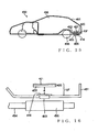
- Fig. 9 is a view showing constructions of a third embodiment of the transmitted sound control apparatus 10C of the present invention and an automotive vehicle 150 provided with the third embodiment of the transmitted sound control apparatus 10C.
- Fig. 10A is an enlarged view of the transmitted sound control apparatus 10C shown in Fig. 9, and
- Fig. 10B is a view showing the transmitted sound control apparatus 10C as viewed in a direction of arrow A of Fig. 10A .
- three opening portions 154L, 154C and 154R are provided, in a horizontal row in a width direction of the vehicle 150, in a dashboard 153 that is a boundary surface partitioning between an engine room 151 and an interior space 152 of a passenger compartment.
- the opening portions 154L, 154C and 154R are each in the shape of a true circle of a same diameter. Between an engine 155 in the engine room 151 and the opening portions 154L, 154C and 154R is provided a duct 157 for directing air intake sound, emitted from the engine 155, to the opening portions 154L, 154C and 154R.
- the transmitted sound control apparatus 10C is constructed to allow air intake sound, propagated from the engine 155 into the passenger compartment interior space 152 via the duct 157 and opening portions 154L, 154C and 154R, to be heard by the human listener as sound having adjusted frequency characteristics.
- the transmitted sound control apparatus 10C includes a film 119, a pair of left and right sound insulating plates 120L and 120R, a pair of upper and lower support members 130U and 130D, and a control section 149.
- the film 119 is a polyester film, and it is attached to the opening portions 154L, 154C and 154R of the dashboard 153 in such a manner as to close or cover the opening portions 154L, 154C and 154R and thereby close the passenger compartment interior space 152.
- the sound insulating plate 120L comprises a lamination of a sound reflecting plate 121L and a sound absorbing member 122L
- the sound insulating plate 120R comprises a lamination of a sound reflecting plate 121R and a sound absorbing member 122R
- the sound reflecting plate 121L is made by forming a material (e.g., acryl resin), having a sound insulting performance or capability (or area density) equal to or less than that of the dashboard 153, into a plate shape having a length and wide greater than the diameter of the opening portions 154L, 154C and 154R.
- the sound reflecting plate 121R is made by forming the same material as the sound reflecting plate 121L into a plate shape having the same size as the sound reflecting plate 121L.
- the sound absorbing members 122L and 122R are each made of a porous material, such as glass wool.
- the upper and lower support members 130U and 130D perform a first function of supporting the sound insulating plates 120L and 120R in such a manner that respective one surfaces of the sound absorbing members 122L and 122R of the plates 120L and 120R are opposed to the opening portions 154L, 154C and 154R with an interval d defined between the sound insulating plates 120L and 120R and the dashboard 153, and a second function of moving the two sound insulating plates 120L and 120R toward or away from each other along a plane parallel to the row of the opening portions 154L, 154C and 154R.
- the support member130U projects from a position of the dashboard 153, located slightly above the opening portions 154L, 154C and 154R, into the passenger compartment interior space 152.
- the lower support member130D projects from a position of the dashboard 153, located slightly below the opening portions 154L, 154C and 154R, into the passenger compartment interior space 152.
- a rail 131U extending in the vehicle width direction i.e., direction parallel to the horizontal row of the opening portions 154L, 154C and 154R
- a rail 131D extending in the vehicle width direction is provided on the upper surface of the lower support member130D opposed to the upper support member130U.
- the control section 149 receives, from a number-of-rotation sensor (crank angle sensor) provided in the engine 155, a detection signal indicative of the number of rotations of the engine 155. Then, once the number of rotations of the engine 155 increases, the control section 149 supplies each of the above-mentioned drive sections 132UL, 132UR, 132DL and 132DR with a control signal for moving the sound insulating plates 120L and 120R outwardly (i.e., in a direction where the plates120L and 120R get away from each other).
- a number-of-rotation sensor crank angle sensor
- the control section 149 supplies each of the drive sections 132UL, 132UR, 132DL and 132DR with a control signal for moving the sound insulating plates 120L and 120R inwardly (i.e., in a direction where the plates120L and 120R get closer to each other).
- the drive sections 132UL, 132UR, 132DL and 132DR move the sound insulating plates 120L and 120R outwardly (away from each other) or inwardly (toward each other).
- the transmitted sound control apparatus 10C components of various frequency bands of air intake sound emitted from the engine 155 during travel of the automotive vehicle 150 are changed when the sound transmits through the film 119, when it is reflected from the sound reflecting plates 121L and 121R and when it is diffracted, via spaces adjacent to the lateral sides of the interval d between the reflecting plates 121L and 121R and the dashboard 153, to behind the reflecting plates121L and 121R, so that the sound can be made to be heard by the human listener, present in the passenger compartment interior space 152, as sound having desired frequency characteristics.
- the transmitted sound control apparatus 10C When the number of rotations of the engine 155 has increased and frequencies of harmonics (i.e., frequencies of a fundamental and second-order harmonic, third-order harmonic, ...) included in air intake sound have increased, the transmitted sound control apparatus 10C operates to decrease the area of the surfaces of the plates 120L and 120R opposed to the opening portions 154L, 154C and 154R. Conversely, when the number of rotations of the engine 155 has decreased and frequencies of harmonics included in air intake sound have decreased, the transmitted sound control apparatus 10C operates to increase the area of the surfaces of the plates 120L and 120R opposed to the opening portions 154L, 154C and 154R.
- the frequency band where the sound pressure level increase amounts start greatly lowering shifts to a higher frequency side as the area of the surfaces of the plates 120L and 120R opposed to the opening portions 154L, 154C and 154R decreases, but shifts to a lower frequency side as the area of the surfaces of the plates 120L and 120R opposed to the opening portions 154L, 154C and 154R increases.
- the transmitted sound control apparatus 10C behaves in such a manner that, when the number of rotations of the engine 155 has increased and frequencies of harmonics included in air intake sound have increased, frequency bands of sound transmitted through the apparatus 10C too shift to a higher frequency side in response to the change of the frequencies of the harmonics.
- the transmitted sound control apparatus 10C can cause the air intake sound to be heard by the human listener after positively selecting desired harmonics of the air intake sound changing in response to the number of rotations of the engine 155.
- Fig. 11 is a view showing constructions of a fourth embodiment of the transmitted sound control apparatus 10D of the present invention and an automotive vehicle 150 provided with the fourth embodiment of the transmitted sound control apparatus 10D.
- Fig. 12A is an enlarged view of the transmitted sound control apparatus 10D shown in Fig. 11, and
- Fig. 12B is a view showing the transmitted sound control apparatus 10D as viewed in a direction of arrow B of Fig. 12A .
- a film 219 is attached to the opening portions 154L, 154C and 154R of the dashboard 153.
- a support member 230 of a circular columnar shape projects from a position of the dashboard 153, located slightly below the opening portions 154L, 154C and 154R, into the passenger compartment interior space 152.
- the support member 230 performs a first function of supporting sound insulating plates 220L and 220R in such a manner that respective one surfaces of sound absorbing members 222L and 222R are opposed to the opening portions 154L, 154C and 154R with an interval d defined between the sound insulating plates 220L and 220R and the dashboard 153, and a second function of rotating the two plates 220L and 220R in opposite directions along a plane parallel to the opening portions 154L, 154C and 154R.
- a right lower corner portion of the sound insulating plate 220L and a left lower corner portion of the sound insulating plate 220R are connected to a distal end portion of the support member 230.
- a drive section 232 is provided in the distal end portion of the support member 230 to which are connected the sound insulating plates 220L and 220R. Under control of a control section 249, the drive section 232 rotates the sound insulating plates 220L and 220R with a connection portion between the sound insulating plates 220L and 220 and the drive section 232 functioning as a rotation axis.
- the control section 249 supplies the drive section 232 with a control signal for rotating the sound insulating plate 220L in a counterclockwise direction and the sound insulating plate 220R in a clockwise direction. Conversely, once the number of rotations of the engine 155 decreases, the control section 249 supplies the drive section 232 with a control signal for rotating the sound insulating plate 220L in the clockwise direction and the sound insulating plate 220R in the counterclockwise direction. Thus, the drive section 232 rotates the sound insulating plates 220L and 220R in accordance with the control signal supplied from the control section 249.
- the transmitted sound control apparatus 10D behaves in such a manner that, when the number of rotations of the engine 155 has increased and frequencies of harmonics included in air intake sound have increased, frequency bands of sound transmitted through the apparatus 10D too shift to a higher frequency side in response to the change of the frequencies of the harmonics.
- the transmitted sound control apparatus 10D allows the air intake sound to be heard by the human listener after positively selecting desired harmonics of the air intake sound changing in response to the number of rotations of the engine 155.
- Fig. 13 is a view showing constructions of a fifth embodiment of the transmitted sound control apparatus 10E of the present invention and an automotive vehicle 350 provided with the fifth embodiment of the transmitted sound control apparatus 10E.
- Fig. 14 is an enlarged view of the transmitted sound control apparatus 10E shown in Fig. 13 .
- an opening portion 353 is provided in a portion of a bottom plate 353 of a body 351 of the automotive vehicle 350 immediately above an exhaust pipe 354.
- the transmitted sound control apparatus 10E is constructed to allow exhaust sound, emitted from the exhaust pipe 354 during travel of the automotive vehicle 350, to be heard by a human listener, present in a passenger compartment inner space 358, as sound having adjusted frequency characteristics.
- the transmitted sound control apparatus 10E includes a film 319 and a sound insulating plate 320.
- the film 319 is a polyester film, and it is attached to the opening portion 353 in such a manner as to close or cover a side of the opening portion 353 facing toward the passenger compartment inner space 358 and thereby prevent foreign matters, such as water and sand, and air (hot and cold air) from entering from outside the passenger compartment into the passenger compartment.
- the sound insulating plate 320 comprises a lamination of a sound reflecting plate 321 and a sound absorbing member 322.
- the sound insulating plate 320 is supported in such a manner that one surface of the sound absorbing member 322 of the plate 320 is opposed to the opening portion 353 with an interval d defined between the sound insulating plate 320 and the bottom plate 352 of the body 351.
- the sound insulating plate 320 may be supported by any of various means.
- the sound insulating plate 320 may be attached to a portion of a seat (not shown), fixed to the bottom plate 352, immediate above the opening portion 353.
- the transmitted sound control apparatus 10E In the transmitted sound control apparatus 10E, components of various frequency bands of exhaust sound emitted from the exhaust pipe 354 during travel of the automotive vehicle 350 are changed when the sound transmits through the film 319, when it is reflected from the sound reflecting plate 321 and when it is diffracted, via lateral sides of the interval d between the reflecting plate 321 and the film 319, to behind the reflecting plate 321.
- the transmitted sound control apparatus 10E behaves in such a manner that, when the number of rotations of the engine 155 has increased and frequencies of harmonics included in exhaust sound of the engine 155 have increased, frequency bands of sound transmitted through the apparatus 10E too shift to a higher frequency side in response to the change of the frequencies of the harmonics.
- the transmitted sound control apparatus 10E allow the exhaust sound to be heard by the human listener after positively selecting desired harmonics of the exhaust sound changing in response to the number of rotations of the engine 155.
- Fig. 15 is a view showing constructions of a sixth embodiment of the transmitted sound control apparatus 10F of the present invention and an automotive vehicle 450 provided with the sixth embodiment of the transmitted sound control apparatus 10F.
- Fig. 16 is an enlarged view of the transmitted sound control apparatus 10F shown in Fig. 15 .
- an opening portion 453 is provided in a portion of a body 451 of the automotive vehicle 450 immediately above a muffler 455.
- the transmitted sound control apparatus 10F is constructed to allow muffled exhaust sound, emitted from the muffler 455 to propagate into a passenger compartment interior space 458 during travel of the automotive vehicle 450, to be heard by a human listener, present in a passenger compartment inner space 458, as sound having adjusted frequency characteristics.
- the film 419 is attached to the opening portion 453 in such a manner as to close or cover a side of the opening portion 453 facing toward the passenger compartment inner space 458.
- a sound insulating plate 420 is supported in such a manner that one surface of a sound absorbing member 422 of the plate 420 is opposed to the opening portion 453 with an interval d defined between the sound insulating plate 420 and the body 451.
- the sound insulating plate 420 may be supported by any of various means.
- the sound insulating plate 420 may be supported by being fixed to the distal ends of a plurality of supporting struts projecting upwardly from a peripheral region of the opening portion 453 of the body 451.
- the transmitted sound control apparatus 10F components of various frequency bands of muffled exhaust sound emitted from the muffler 455 during travel of the automotive vehicle 450 are changed when the sound transmits through the film 419, when it is reflected from a sound reflecting plate 421 of the sound insulating plate 420 and when it is diffracted, via lateral sides of the interval d between the reflecting plate 421 and the film 419, to behind the reflecting plate 421.
- the transmitted sound control apparatus 10F behaves in such a manner that, when the number of rotations of the engine 155 has increased and frequencies of harmonics included in exhaust sound of the engine 155 have increased, frequency bands of sound transmitted through the apparatus 10F too shift to a higher frequency side in response to the change of the frequencies of the harmonics.
- the transmitted sound control apparatus 10F allow the exhaust sound to be heard by the human listener after positively selecting desired harmonics of the exhaust sound changing in response to the number of rotations of the engine 155.
- a tension impartment mechanism 60 may be provided for imparting tension to the film 3 closing the opening portion 2, as shown in Fig. 17 .
- the inner periphery of the opening portion 2 of the wall 1 projects inwardly of the room to define a hollow cylindrical section 62, and the hollow cylindrical section 62 is closed at its open end with the film 3.
- the film 3 is attached at its outer peripheral portion to a ring-shaped frame 63, and this frame 63 is supported by the tension impartment mechanism 60 with the hollow cylindrical section 62 surrounded by the ring-shaped frame 63.
- the tension impartment mechanism 60 includes a mechanism for moving the ring-shaped frame 63 toward the outside of the room. As the tension impartment mechanism 60 moves the ring-shaped frame 63 toward the outside of the room, the frame 63 pulls the outer peripheral portion of the film 3 toward the outside of the room to thereby increase tension imparted to the film 3 that is supported at the open end of the hollow cylindrical section 62.
- this transmitted sound control apparatus low-frequency components of sound, propagated from outside the room into the room through the hollow cylindrical section 62, can be greatly attenuated by the tension impartment mechanism 60 imparting an increased tension to the film 3.
- a plurality of types of films 3 having different thicknesses may be prepared in advance so that any desired one of the plurality of types of films 3 can be selectively (i.e., replaceably) used to close the opening portion 2.
- a plurality of types of sound insulating plates 20 having different characteristics may be prepared in advance so that any desired one of the plurality of types of sound insulating plates 20 can be selectively (i.e., replaceably) used and supported in opposed relation to the opening portion 2.
- the opening portion 2 need not necessarily be of a generally circular shape and may be of a rectangular or any other desired shape. Further, the number of the opening portion 2 may be two or four or more. In such a case, the opening portions may be differentiated from each other in shape and/or size. Further, the plurality of opening portions 2 may be disposed in any other desired arrangement or layout than in a left-right row as illustratively shown in Fig. 6 . Alternatively, the plurality of opening portions 2 may be disposed in a layout such that a particular pattern is presented by these opening portions 2.
- the support mechanism supporting the sound insulating plate 20 has the rotation shaft 23 projecting toward the wall 1 at right angles thereto, and a posture of the sound insulating plate 20 relative to the opening portions 2L, 2C and 2R of the wall 1 can be changed as need by being rotated about the rotation shaft 23.
- any other suitable means than the above-described may be employed for changing the posture of the sound insulating plate 20 relative to the opening portions 2L, 2C and 2R of the wall 1.
- the support mechanism supporting the sound insulating plate 20 may have a rotation shaft extending in parallel to the wall 1 and stretchable and contractable in an up-down or left-right direction so that the posture of the sound insulating plate 20 relative to the opening portions 2L, 2C and 2R of the wall 1 can be changed as need by being rotated about the rotation shaft extending in parallel to the wall 1.
- the support mechanism supporting the sound insulating plate 20 has the translation shaft extending normally to the surface of the wall 1, and the sound insulating plate 20 is moved along the translation shaft toward or away from the wall 1 to thereby change (decrease or increase) the distance d between the openings 2L, 2C and 2R of the wall 1 and the sound insulating plate 20.
- the support mechanism for supporting the sound insulating plate 20 may have a translation shaft extending in the up-down or left-right direction in parallel relation to the surface of the wall 1 so that the area of the surface of the sound insulating plate 20 opposed to the openings 2L, 2C and 2R can be changed by the sound insulating plate 20 being translated along the translation shaft extending in the up-down or left-right direction.
- the sound insulating plate 20 it is only necessary that the sound insulating plate 20 be supported by a means or mechanism for translating the plate 20. Further, as shown in Fig.
- link members 530U and 530D each stretchable and contractable via a pantagraph mechanism, may be provided between positions of the wall 1 located slightly above and below the row of the opening portions 2L, 2C and 2R and one surface of the sound absorbing member 22 of the sound insulating plate 20 opposed to the wall 1, so as to change the distance between the sound insulating plate 20 and the opening portions 2L, 2C and 2R through stretch or contraction of the link members 530U and 530D.
- a packing member 531 may be provided on and along a peripheral region of the one surface of the sound absorbing member 22 of the sound insulating plate 20, and another packing member 532 may be provided on the wall 1 in opposed relation to the packing member 531.
- a slight gap defined between the sound insulating plate 20 and the wall 1 when the link members 530U and 530D are in a completely contracted or collapsed position can be closed with the packing members 531 and 532, so that sound propagation from outside the room into the room can be completed blocked.
- the sound insulating plate 20 may be supported by a support member(s) made of a shape-memory alloy or the like so that the position and posture of the sound insulating plate 20 relative to the opening portion 2 can be changed with a finger(s) of the human listener.
- the sound insulating plate may be constructed of only the reflecting plate, and the sound absorbing member may be attached to or provided on the film. In short, it is only necessary that the sound absorbing member be provided between the opening portion and the reflecting plate.
- the opening portion may have no film attached thereto so that an outdoor sound having been transmitted through the opening portion(s) is propagated directly to the sound insulating plate.
- the area of the surface of the sound insulating plate 20 opposed to the openings 2L, 2C and 2R is controlled in accordance with the number of rotations of the engine 155.
- the area of the surface of the sound insulating plate 20 opposed to the openings 2L, 2C and 2R may be controlled in accordance with detection information indicative of a traveling state, such as a traveling velocity, accelerator depression amount, number of passengers on a front passenger's seat and rear seat, fuel consumption amount per time, exhaust gas discharge amount per time or carbon dioxide discharge amount per time, of the automotive vehicle 150.
- sound produced from a source other than the engine, exhaust gas pipe and muffler may be taken into the passenger compartment so as to be heard by the human listener as sound having adjusted frequency components.
- an opening portion may be provided in a portion of the automotive vehicle body immediately above a rear road wheel and a film may be attached to the opening portion to close or cover the opening portion, so that sound of a tire transmitted through the film into the passenger compartment can be made to be heard by the human listener as sound having adjusted frequency components.
- an opening portion may be provided in a portion of a ceiling of the automotive vehicle body and a film may be attached to the opening portion to close or cover the opening portion, so that wind roar transmitted through the film into the passenger compartment can be made to be heard by the human listener as sound having adjusted frequency components.
- the sound to be subjected to frequency component adjustment by the transmitted sound control apparatus may be any sound as long as the sound is produced outside the room or passenger compartment of the automotive vehicle which the human listener is in, rather than being limited to the sound described above in relation to the first to sixth embodiments.
- the area of the surface of the sound insulating plate opposed to the opening portion is changed by the control section 149 or 249 moving or rotating the sound insulating plate.
- the area of the surface of the sound insulating plate opposed to the opening portion may be changed by changing the shape of the opening portion itself.
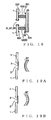
- the sound insulating plate 20 comprises a lamination of the flat sound reflecting plate and sound absorbing material.
- the sound insulating plate 20 may be replaced with a sound insulating plate 20' having a shape convexly curved toward the opening portion 2, as illustratively shown in Fig. 19A .
- the sound insulating plate 20 may be replaced with a sound insulating plate 20" having a shape convexly curved away from the opening portion 2, as illustratively shown in Fig. 19B .
- an opening portion may be provided in a sound insulating wall in a musical instrument practicing room, which is sound insulated from the outside by the sound insulating wall, with a film attached to or provided on the opening portion to close or cover the opening portion, and a sound insulating plate may be provided inside the opening (i.e., in the interior of the practicing room).
- frequency components of noise (sound) produced outside the practicing room is adjusted by the film and sound insulating plate so that the noise can be made to be heard by a human listener (human player) in the room as sound of acoustic quality that would not disturb the musical instrument practice.
- an opening portion may be provided in a wall of a housing having a noise source, such as a boiler, accommodated therein and sound-insulated from the outside by the wall, with a film attached to the opening portion to close or cover the opening portion and with a sound insulating plate provided outside the opening portion.
- a modified embodiment can adjust frequency components of noise by means of the film and sound insulating plate and make the noise to be heard by a person present outside the housing (e.g., pedestrian) as sound with an alleviated offensive or uncomfortable feeling.
- the sound insulating plate may be replaced with a structure already provided inside the dashboard 153 of the automotive vehicle 150 (i.e., in the passenger compartment interior space 152) or outside the dashboard 153 (i.e., in the engine room 151).
- an interval d may be secured between a surface, opposite from an air outlet, of an airconditioner unit fixed substantially centrally on the dashboard 153 and the dashboard 153, and an opening portion 154' communicating with the engine room 151 may be provided in a position of the dashboard 153 facing the airconditioner unit with a film 119' attached to the opening portion 154'.
- the modified embodiment can achieve the same advantageous benefits as the third and fourth embodiments without using any sound insulating plate.
- the upper and lower support members 130U and 130D and the rails 131U and 131D extend in the vehicle width direction (i.e., direction parallel to the row of the opening portions 154L, 154C and 154R), and the sound insulating plates 120L and 120R are moved along the rails 131U and 131D.
- the sound insulating plates 120L and 120R may be moved in a direction slightly inclined relative to the direction parallel to the row of the opening portions 154L, 154C and 154R.
- both the area of the surfaces of the sound insulating plates 120L and 120R opposed to the opening portion and the interval d between the sound insulating plates 120L and 120R and the opening portions 154L, 154C and 154R can be changed by moving the sound insulating plates 120L and 120R.
- the two sound insulating plates 220L and 220R are supported by one support member 230.
- the two sound insulating plates 220L and 220R may be supported by separate support members.
- the transmitted sound control apparatus of the present invention has been described above as applied to control sound transmitted from outside of a room into the room, it may be applied to control sound transmitted from outside of a vehicle into the vehicle.
Landscapes
- Physics & Mathematics (AREA)
- Acoustics & Sound (AREA)
- Engineering & Computer Science (AREA)
- Mechanical Engineering (AREA)
- Multimedia (AREA)
- Soundproofing, Sound Blocking, And Sound Damping (AREA)
- Building Environments (AREA)
Abstract
Wall (1) partitioning between outside and inside of a room has an opening portion (2) closed with a film (3). Sound insulating plate (20), comprising a lamination of a sound reflecting plate (21) and a sound absorbing member (22), is supported in opposed relation to the opening portion and at an interval from the opening portion. Sound transmitted from outside of the room into the room through the film (3) is reflected from the sound reflecting plate (21) and then diffracted via sides of the interval, defined between the sound reflecting plate (21) and the wall (1), to behind the reflecting plate to reach a human listener. Thus, with a mechanical construction, sound, propagated from outside the room into the room, can be made to be heard as sound of frequency characteristics desired by a human listener present in the room.
Description
- The present invention relates a technique for controlling an acoustic quality of sound coming from outside a room (or outside a vehicle) into the room (or vehicle).
- Japanese Patent No.
2755094 2755094 - However, while the person in the room may feel a cooped-up feeling if sound propagated from outside the room (i.e., outdoor sound) is completely blocked by walls etc., the person may feel noisy if sound from outside the room is heard with an original (i.e., unchanged) acoustic quality. With a sound signal processing system including a microphone and a speaker, an outdoor sound can be made to be heard as sound of an acoustic quality suiting a preference of the person; in this case, however, a power supply is required, so that a necessary apparatus construction would increase in size.
- In view of the foregoing, it is an object of the present invention to provide a technique for allowing sound, propagated from outside a room into the room, to be heard as sound having frequency characteristics desired by a person (or human listener) present in the room.
- The present invention provides an improved transmitted sound control apparatus which includes a sound insulating plate supported at an interval from a boundary surface having an opening portion and in opposed relation to the opening. In the present invention, sound produced outside the boundary surface transmits through the opening portion to propagate to inside of the boundary surface. Then, the sound (i.e., transmitted sound) is reflected from the sound insulating plate, and the thus-reflected sound is diffracted via side edge portions of the interval, defined between the sound insulating plate and the boundary surface, rearwardly (i.e., rearwardly assuming that the sound reflected direction is referred to as forwardly) to behind the sound insulating plate and propagate to the human listener. In the present invention, components of various frequency bands of the sound, having transmitted through the opening portion to propagate to inside of the boundary surface, are changed when it is reflected from the sound insulating plate and when it is diffracted rearwardly to behind the sound insulating plate, so that the sound can be made to be heard as sound having frequency characteristics desired by the human listener.
- The following will describe embodiments of the present invention, but it should be appreciated that the present invention is not limited to the described embodiments and various modifications of the invention are possible without departing from the basic principles. The scope of the present invention is therefore to be determined solely by the appended claims.
- For better understanding of the object and other features of the present invention, its preferred embodiments will be described hereinbelow in greater detail with reference to the accompanying drawings, in which:
-
Fig. 1 is a diagram showing an example general setup of a first embodiment of a transmitted sound control apparatus of the present invention; -
Fig. 2 is a graph showing sound pressure level increase amount vs. frequency characteristics in a room provided with the transmitted sound control apparatus ofFig. 1 ; -
Fig. 3 is a graph showing sound pressure level increase amount vs. frequency characteristics in the room provided with the transmitted sound control apparatus ofFig. 1 ; -
Fig. 4 is a graph showing sound pressure level increase amount vs. frequency characteristics in the room provided with the transmitted sound control apparatus ofFig. 1 ; -
Fig. 5 is a block diagram showing a general setup of a transmitted sound control apparatus constructed as a specific applied example of the embodiment ofFig. 1 ; -
Fig. 6 is a sectional view of the transmitted sound control apparatus ofFig. 5 taken along the A - A' line ofFig. 5 ; -
Fig. 7 is a sectional view of the transmitted sound control apparatus ofFig. 5 taken along the A - A' line ofFig. 5 ; -
Fig. 8 is a view showing a construction of a second embodiment of the transmitted sound control apparatus of the present invention; -
Fig. 9 is a view showing constructions of a third embodiment of the transmitted sound control apparatus of the present invention and an automotive vehicle provided with the third embodiment of the transmitted sound control apparatus; -
Figs. 10A and 10B are enlarged views of the transmitted sound control apparatus shown inFig. 9 ; -
Fig. 11 is a view showing constructions of a fourth embodiment of the transmitted sound control apparatus of the present invention and an automotive vehicle provided with the fourth embodiment of the transmitted sound control apparatus; -
Fig. 12 is an enlarged view of the transmitted sound control apparatus shown inFig. 11 ; -
Fig. 13 is a view showing constructions of a fifth embodiment of the transmitted sound control apparatus of the present invention and an automotive vehicle provided with the fifth embodiment of the transmitted sound control apparatus; -
Fig. 14 is an enlarged view of the transmitted sound control apparatus shown inFig. 13 ; -
Fig. 15 is a view showing constructions of a sixth embodiment of the transmitted sound control apparatus of the present invention and an automotive vehicle provided with the sixth embodiment of the transmitted sound control apparatus; -
Fig. 16 is an enlarged view of the transmitted sound control apparatus shown inFig. 15 ; -
Fig. 17 is a view showing a construction of a tension impartment mechanism employed in another embodiment of the transmitted sound control apparatus of the present invention; -
Fig. 18 is a view showing another embodiment of the transmitted sound control apparatus of the present invention; and -
Figs. 19A and 19B view showing other embodiments of the transmitted sound control apparatus of the present invention. -
Fig. 1 is a diagram showing an example general setup of a first embodiment of a transmittedsound control apparatus 10 of the present invention. The transmittedsound control apparatus 10 ofFig. 1 includes anopening portion 2 formed in awall 1 that functions as a boundary surface partitioning between an outside and an inside of the room, and it is arranged to allow sound, propagated from the outside of the room into the room, to be heard by a human listener as sound having adjusted frequency characteristics. - As shown in
Fig. 1 , the transmittedsound control apparatus 10 also includes afilm 3, a soundinsulating plate 20, and an appropriate number of rod-shaped support members 30. - The
film 3, which is a polyester film, is attached to or provided on thewall 1 in such a manner as to close or cover theopening portion 2. The soundinsulating plate 20, which is disposed in the inside of the room, comprises a lamination of a resin-madesound reflecting plate 21 and asound absorbing member 22. Thesound reflecting plate 21 is made by forming a material (e.g., acryl resin), having a sound insulting performance or capability (or area density) equal to or less than that of thewall 1, into a plate shape. Thesound absorbing member 22 is made of a porous material, such as glass wool. - As seen in
Fig. 1 , thesupport members 30 together constitute asupport mechanism 30 that supports the soundinsulating plate 20 in such a manner that a surface of thesound absorbing member 22 is opposed to theopening portion 2 with an interval d defined between the soundinsulating plate 20 and thewall 1. In a case where the soundinsulating plate 20 is of a rectangular shape, it may be fixed by respective one ends of foursupport members 30 being passed through portions of the soundinsulating plate 20 near the four corners of theplate 20 and the respective other ends of the foursupport members 30 being passed through or embedded in thewall 1. In such a case, four bolts may be used as the foursupport members 30 each sandwiching the soundinsulating plate 20 with two nuts threaded on the bolt. Such an arrangement allows the distance d between thesound insulating plate 20 and thewall 1 to be adjusted in response to manipulation of the nuts. - The forgoing have briefed the construction of the transmitted
sound control apparatus 10. A sound produced outside the room propagates or transmits through thefilm 3, closing theopening portion 2, into the room. Then, the sound transmitted through thefilm 3 is reflected from thesound reflecting plate 21 of the soundinsulating plate 20, and the thus-reflected sound is difracted via side edge portions of the interval d, defined between thesound reflecting plate 21 and thewall 1, rearward to behind thereflecting plate 21 to propagate to or reach the human listener. In the instant embodiment, components of various frequency bands of the sound produced outside the room are changed when the sound transmits through thefilm 3, when it is reflected from thesound reflecting plate 21 and when it is diffracted to behind thereflecting plate 21, so that the sound can be made to be heard by a human listener as sound having desired frequency characteristics. In order to verify advantageous benefits of the instant embodiment, the inventor of the present invention conducted the following test. - First, the inventor set different Conditions 1 - 13 that differ in presence/absence (i.e., provided/not-provided) of the
opening 2 in thewall 1, presence/absence of closure, by thefilm 3, of theopening portion 2, presence/absence (i.e., provided/not-provided) of the soundinsulating plate 20, thickness of thefilm 3, distance between theopening portion 2 and the soundinsulating plate 20 and size of the soundinsulating plate 20, as shown in a table below. Then, the inventor caused a pink noise sound signal to be generated as sound outside thewall 1; picked up the sound via a microphone placed within the room at a distance of 50 cm from thewall 1; and determined a sound pressure level of every one-third octave of the sound picked up by the microphone under each of Conditions 1 - 13. In the test, theopening portion 2 formed in thewall 1 comprises three opening portions each having a diameter of 40 mm and disposed in a row at a 60-mm pitch. Further, the sound pressure levels of the individual frequency bands obtained underCondition 1 were set as reference sound pressure levels, and frequency characteristics of differences, from the reference sound pressure levels, of sound pressure levels of the individual frequency bands obtained under Conditions 2 - 13 (hereinafter referred to as "sound pressure level increase amounts" (dB)) are plotted inFigs. 2 ,3 and 4 . -
TABLE 1 Condition Opening Portion Film Sound Insulating Plate Film Thickness (µm) Size (mm) Distance (mm) Curve In Graphs of Figs. 2 - 4 Line Type 1 Not-Provided Not-Provided Not-Provided - - - - 2 Provided Not-Provided Not-Provided - - - a0(b0) ------------ 3 Provided Provided Not-Provided 38 - - a1 --- --- --- 4 Provided Provided Not-Provided 50 - - a2 --- . --- . 5 Provided Provided Not-Provided 75 - - a3 --- .. --- 6 Provided Provided Not-Provided 100 - - a4 --- --- . -- 7 Provided Provided Not-Provided 125 - - a5 - - - - - - - 8 Provided Provided Not-Provided 188 - - a6 -- . -- . -- .. 9 Provided Provided Provided 50 260 × 180 15 b1 -- .. -- .. -- 10 Provided Provided Provided 50 180 × 60 15 b2(c2) -- .. -- .. -- 11 Provided Provided Provided 50 180 × 60 0 c1 --- . --- . 12 Provided Provided Provided 50 180 × 60 30 c3 --- .. --- 13 Provided Not-Provided Provided 50 180 × 60 45 c4 ....................... - According to the graphs, the following relationships exist between the
film 3 closing theopening portion 2 of thewall 1, the size of the soundinsulating plate 20 and the distance between theopening portion 2 and the soundinsulating plate 20 and the sound pressure level increase amounts of the individual frequency bands. - (1) In
Fig. 2 , a graph curve a0 indicates a sound pressure level increase amount vs. frequency characteristic in the case where theopening portion 2 in thewall 1 is not closed with thefilm 3. The graph curves a1, a2, a3, a4, a5 and a6 indicate sound pressure level increase amount vs. frequency characteristics in the case where theopening portion 2 in thewall 1 is closed withfilms 3 of different thicknesses. From the graph curves a0, a1, a2, a3, a4, a5 and a6, it can been seen that sound pressure level attenuation amounts in frequency bands higher than about 315 Hz in the case where theopening portion 2 is closed with thefilm 3 are greater than those in the case where theopening portion 2 is not closed with thefilm 3. Further, in the case where theopening portion 2 is closed with thefilm 3, sound pressure level increase amounts in the frequency bands higher than about 315 Hz decrease as the thickness of thefilm 3 increases; namely, the sound pressure level attenuation amounts in frequency bands higher than about 315 Hz increase as the thickness of thefilm 3 increases. Thus, by changing the thickness of thefilm 3 closing theopening portion 2, it is possible to control the sound pressure level increase amounts in predetermined frequency bands higher than a predetermined frequency (in the instant embodiment, 315 Hz). - (2) In
Fig. 3 , a graph curve b0 indicates a sound pressure level increase amount vs. frequency characteristic in the case where theopening portion 2 in thewall 1 is not closed with thefilm 3. Further, graph curves b1 and b2 indicate sound pressure level increase amount vs. frequency characteristics in the case where the size of thesound insulating plate 20 opposed to theopening portion 2 was differentiated with the thickness of thefilm 3 closing theopening portion 2 in thewall 1 kept the same. InFig. 3 , sound pressure level increase amounts in frequency bands higher than 1,000 Hz of a graph curve b1 are much lower than those in frequency bands higher than 1,000 Hz of the graph curve b0. Further, sound pressure level increase amounts in frequency bands higher than 1,600 Hz of a graph curve b2 are much lower than those in frequency bands higher than 1,600 Hz of the graph curve b0. From these graph curves b1 and b2 ofFig. 3 , it can be seen that the frequency band where the sound pressure level increase amounts start greatly lowering shifts to a higher frequency side (or lower frequency side) as the size of thesound insulting plate 20 is reduced (or increased). Thus, the frequency band where the sound pressure level increase amounts start greatly lowering can be controlled by changing the size of thesound insulting plate 20. - (3) Graph curves c1, c2, c3 and c4 of
Fig. 4 indicate sound pressure level increase amount vs. frequency characteristics in the case where the distance between thewall 1 and thesound insulating plate 20 was changed in steps of 15 mm from 0 mm to 45 with the thickness of thefilm 3, closing theopening portion 2 in thewall 1, kept the same. Focusing on frequency bands higher than 250 Hz but lower than 1,000 Hz inFig. 4 , there is little difference in sound pressure level increase amount among the graph curves c2, c3 and c4 (with the distance between thewall 1 and thesound insulating plate 20 set in the range of 15 mm - 45 mm), but sound pressure level increase amounts of the graph curve c1 (with the distance between thewall 1 and thesound insulating plate 20 set at 0 mm) are markedly lower than those of the graph curves c2, c3 and c4. Thus, the sound pressure level increase amounts in the predetermined frequency bands higher than 250 Hz but lower than 1,000 Hz can be decreased by decreasing the distance d between thewall 1 and thesound insulating plate 20 to 0 mm from a predetermined value greater than 0 mm (value in the range of 15 mm - 45 mm in the instant embodiment). Further, the sound pressure level increase amounts in the predetermined frequency bands higher than 250 Hz but lower than 1,000 Hz can be increased by increasing the distance d between thewall 1 and thesound insulating plate 20 from 0 mm to a desired value (15 mm in the instant embodiment). - On the basis of the aforementioned test results, the inventor has invented a transmitted
sound control apparatus 10A, as a specific applied example of the transmittedsound control apparatus 10 ofFig. 1 , which includes a support mechanism for supporting thesound insulating plate 20 in such a manner as to permit a change in a positional relationship of thesound insulating plate 20 relative to theopening portion 2. -
Fig. 5 is a block diagram showing a general setup of the transmittedsound control apparatus 10A constructed as a specific applied example of theapparatus 10 ofFig. 1 , andFig. 6 is a sectional view of the transmittedsound control apparatus 10A taken along the A - A' line ofFig. 5 , i.e. as viewed in a direction from the interior of the room toward thewall 1. In the transmittedsound control apparatus 10A, as shown inFig. 6 , thewall 1 has three openingportions films wall 1 in such a manner as to close or cover respective ones of the three openingportions - The transmitted
sound control apparatus 10A also includes thesupport mechanism 35 having an actuator 41 that translates a box-shapedcasing member 31 along a translation shaft extending normally to the surface of thewall 1. Anotheractuator 40 is fixed within the casingmember 31. Thisactuator 40 has arotation shaft 23 projecting from the casingmember 31 toward thewall 1 at right angles thereto, and thisrotation shaft 23 is rotatable by theactuator 40. Thesound insulating plate 20 is fixed to the distal end of therotation shaft 23 of theactuator 40 to lie parallel to the surface of thewall 1. Therotation shaft 23 extends normally to the surface of thesound insulating plate 20. As shown inFig. 6 , thesound insulating plate 20 has an elliptical shape, which therefore has uneven dimensions from the rotation center of therotation shaft 23 to the outer peripheral edge thereof. Note that thesound insulating plate 20 may be of any other shape than an elliptical shape as long as it has uneven dimensions from the rotation center of therotation shaft 23 to the outer peripheral edge thereof. For example, therotation shaft 23 may be fixed at its distal end to a position of thesound insulating plate 20, having a circular shape, which is displaced from the center of theplate 20. - As also seen in
Fig. 6 , themiddle opening portion 2C of the three openingportions wall 1 overlaps therotation shaft 23 when viewed in the direction from the interior of the room toward thewall 1. If an angle θ (0 ≦ θ ≦ 90) defined by the long (or main) axis of thesound insulating plate 20 and a line interconnecting the respective centers of thefilms Fig. 6 , a surface of thesound insulating plate 20 opposed to the openingportions sound insulating plate 20 and the line interconnecting the respective centers of thefilms Fig. 7 , the surface of thesound insulating plate 20 opposed to the openingportions - The
actuator 41 moves or translates thesound insulating plate 20 toward or away from thewall 1 to thereby decrease or increase the distance d between thewall 1 and thesound insulating plate 20. - In the transmitted
sound control apparatus 10A ofFig. 5 , theactuators sound insulating plate 20 opposed to the openingportions wall 1 and thesound insulating plate 20. Thus, the transmittedsound control apparatus 10A can change a way of controlling frequency characteristics of sound, transmitted from outside the room into the room through thefilms portions -
Fig. 8 is a view showing a construction of a second embodiment of the transmittedsound control apparatus 10B of the present invention, where similar elements to those inFig. 1 are indicated by the same reference numerals as inFig. 1 . The second embodiment of the transmittedsound control apparatus 10B is provided outside thewall 1 partitioning between the outside and the inside of the room. Namely, whereas the transmittedsound control apparatus wall 1 and the human listener (sound receiving point) according to the first embodiment, thewall 1 is located between the transmittedsound control apparatus 10B and the human listener (sound receiving point). More specifically, in the transmittedsound control apparatus 10B, thefilm 3 is attached to or provided on a side of theopening portion 2 of thewall 1 facing outside of the room in such a manner as to close or cover theopening portion 2. Thesound insulating plate 20 is supported by thesupport members 30 in such a manner that a surface of thesound absorbing member 22 of thesound absorbing member 22 is opposed to the opening portion 2 (facing toward the interior of the room) with an interval d defined between the sound insulatingplate 20 and thewall 1. - Sound produced outside the room first arrives at the
sound insulating plate 20, so that part of the sound is reflected from thesound reflecting plate 21 of thesound insulating plate 20. Then, the thus-reflected sound and another part of the sound, having propagated past sides of thesound reflecting plate 21, are diffracted rearward to behind the reflecting plate 21 (i.e., behind the sound absorbing member 22), propagate to thefilm 3 via spaces adjacent to the lateral sides of the interval d between thesound reflecting plate 21 and thewall 1, and then reach the human listener. - Whereas sound follows a propagation path of "sound source outside the room →
film 3 →sound reflecting plate 21 → human listener in the room" (hereinafter referred to "propagation path PATH1") in the first embodiment, sound follows a propagation path of "sound source outside the room →sound reflecting plate 21 →film 3 → human listener in the room" (hereinafter referred to "propagation path PATH2") in the second embodiment. If the propagation path PATH1 is divided into three sections: a section between the sound source and thefilm 3; a section between thefilm 3 and thesound reflecting plate 21; and a section between thesound reflecting plate 21 and the human listener in the room, the propagation path PATH1 can be deemed to be a linear system because respective transfer functions in these three section are each linear. Thus, a transfer function of the propagation path PATH2, where the order of thefilm 3 andsound reflecting plate 21 is reversed from that in the propagation path PATH1, is the same as the transfer function of the propagation path PATH1. Therefore, with the second embodiment, sound produced outside the room can be made to be heard by the human listener as sound having the same transmission characteristics (same frequency characteristics) as with the first embodiment of the transmittedsound control apparatus 10. -
Fig. 9 is a view showing constructions of a third embodiment of the transmittedsound control apparatus 10C of the present invention and anautomotive vehicle 150 provided with the third embodiment of the transmittedsound control apparatus 10C.Fig. 10A is an enlarged view of the transmittedsound control apparatus 10C shown inFig. 9, and Fig. 10B is a view showing the transmittedsound control apparatus 10C as viewed in a direction of arrow A ofFig. 10A . In the third embodiment, three openingportions vehicle 150, in adashboard 153 that is a boundary surface partitioning between anengine room 151 and aninterior space 152 of a passenger compartment. The openingportions engine 155 in theengine room 151 and the openingportions duct 157 for directing air intake sound, emitted from theengine 155, to the openingportions - The transmitted
sound control apparatus 10C is constructed to allow air intake sound, propagated from theengine 155 into the passenger compartmentinterior space 152 via theduct 157 and openingportions - As shown in
Fig. 9 , the transmittedsound control apparatus 10C includes afilm 119, a pair of left and rightsound insulating plates lower support members control section 149. Thefilm 119 is a polyester film, and it is attached to the openingportions dashboard 153 in such a manner as to close or cover the openingportions interior space 152. - The
sound insulating plate 120L comprises a lamination of asound reflecting plate 121L and asound absorbing member 122L, while thesound insulating plate 120R comprises a lamination of asound reflecting plate 121R and asound absorbing member 122R. Thesound reflecting plate 121L is made by forming a material (e.g., acryl resin), having a sound insulting performance or capability (or area density) equal to or less than that of thedashboard 153, into a plate shape having a length and wide greater than the diameter of the openingportions sound reflecting plate 121R is made by forming the same material as thesound reflecting plate 121L into a plate shape having the same size as thesound reflecting plate 121L. Thesound absorbing members - The upper and
lower support members sound insulating plates sound absorbing members plates portions plates dashboard 153, and a second function of moving the twosound insulating plates portions - More specifically, the support member130U projects from a position of the
dashboard 153, located slightly above the openingportions interior space 152. The lower support member130D projects from a position of thedashboard 153, located slightly below the openingportions interior space 152. Arail 131U extending in the vehicle width direction (i.e., direction parallel to the horizontal row of the openingportions rail 131D extending in the vehicle width direction is provided on the upper surface of the lower support member130D opposed to the upper support member130U. - Upper and lower end surfaces of the sound insulating
plates rail 131U of theupper support member 130U andrail 131D of thelower support member 130D. Drive sections 132UL and 132UR are provided in longitudinally opposite end portions of therail 131U of theupper support member 130U, while drive sections 132DL and 132DR are provided in longitudinally opposite end portions of therail 131D of thelower support member 130D. Under control of thecontrol section 149, the drive sections 132UL, 132UR, 132DL and 132DR move thesound insulating plates 120L and 120 along therails - The
control section 149 receives, from a number-of-rotation sensor (crank angle sensor) provided in theengine 155, a detection signal indicative of the number of rotations of theengine 155. Then, once the number of rotations of theengine 155 increases, thecontrol section 149 supplies each of the above-mentioned drive sections 132UL, 132UR, 132DL and 132DR with a control signal for moving thesound insulating plates engine 155 decreases, thecontrol section 149 supplies each of the drive sections 132UL, 132UR, 132DL and 132DR with a control signal for moving thesound insulating plates control section 149, the drive sections 132UL, 132UR, 132DL and 132DR move thesound insulating plates - As the
control section 149 moves thesound insulating plates plates plates plates portions control section 149 moves thesound insulating plates plates plates portions - The foregoing have described the construction of the third embodiment of the transmitted
sound control apparatus 10C. In the transmittedsound control apparatus 10C, components of various frequency bands of air intake sound emitted from theengine 155 during travel of theautomotive vehicle 150 are changed when the sound transmits through thefilm 119, when it is reflected from thesound reflecting plates plates dashboard 153, to behind the reflecting plates121L and 121R, so that the sound can be made to be heard by the human listener, present in the passenger compartmentinterior space 152, as sound having desired frequency characteristics. - When the number of rotations of the
engine 155 has increased and frequencies of harmonics (i.e., frequencies of a fundamental and second-order harmonic, third-order harmonic, ...) included in air intake sound have increased, the transmittedsound control apparatus 10C operates to decrease the area of the surfaces of theplates portions engine 155 has decreased and frequencies of harmonics included in air intake sound have decreased, the transmittedsound control apparatus 10C operates to increase the area of the surfaces of theplates portions - As can be seen from the results shown in
Fig. 3 , the frequency band where the sound pressure level increase amounts start greatly lowering shifts to a higher frequency side as the area of the surfaces of theplates portions plates portions sound control apparatus 10C behaves in such a manner that, when the number of rotations of theengine 155 has increased and frequencies of harmonics included in air intake sound have increased, frequency bands of sound transmitted through theapparatus 10C too shift to a higher frequency side in response to the change of the frequencies of the harmonics. As a result, the transmittedsound control apparatus 10C can cause the air intake sound to be heard by the human listener after positively selecting desired harmonics of the air intake sound changing in response to the number of rotations of theengine 155. -
Fig. 11 is a view showing constructions of a fourth embodiment of the transmittedsound control apparatus 10D of the present invention and anautomotive vehicle 150 provided with the fourth embodiment of the transmittedsound control apparatus 10D.Fig. 12A is an enlarged view of the transmittedsound control apparatus 10D shown inFig. 11, and Fig. 12B is a view showing the transmittedsound control apparatus 10D as viewed in a direction of arrow B ofFig. 12A . - In the transmitted
sound control apparatus 10D, as shown inFig. 11 , afilm 219 is attached to the openingportions dashboard 153. Asupport member 230 of a circular columnar shape projects from a position of thedashboard 153, located slightly below the openingportions interior space 152. Thesupport member 230 performs a first function of supportingsound insulating plates sound absorbing members portions plates dashboard 153, and a second function of rotating the twoplates portions - More specifically, a right lower corner portion of the
sound insulating plate 220L and a left lower corner portion of thesound insulating plate 220R are connected to a distal end portion of thesupport member 230. Adrive section 232 is provided in the distal end portion of thesupport member 230 to which are connected thesound insulating plates control section 249, thedrive section 232 rotates the sound insulatingplates plates 220L and 220 and thedrive section 232 functioning as a rotation axis. - Once the number of rotations of the
engine 155 increases, thecontrol section 249 supplies thedrive section 232 with a control signal for rotating thesound insulating plate 220L in a counterclockwise direction and thesound insulating plate 220R in a clockwise direction. Conversely, once the number of rotations of theengine 155 decreases, thecontrol section 249 supplies thedrive section 232 with a control signal for rotating thesound insulating plate 220L in the clockwise direction and thesound insulating plate 220R in the counterclockwise direction. Thus, thedrive section 232 rotates the sound insulatingplates control section 249. The transmittedsound control apparatus 10D behaves in such a manner that, when the number of rotations of theengine 155 has increased and frequencies of harmonics included in air intake sound have increased, frequency bands of sound transmitted through theapparatus 10D too shift to a higher frequency side in response to the change of the frequencies of the harmonics. As a result, the transmittedsound control apparatus 10D allows the air intake sound to be heard by the human listener after positively selecting desired harmonics of the air intake sound changing in response to the number of rotations of theengine 155. -
Fig. 13 is a view showing constructions of a fifth embodiment of the transmittedsound control apparatus 10E of the present invention and anautomotive vehicle 350 provided with the fifth embodiment of the transmittedsound control apparatus 10E.Fig. 14 is an enlarged view of the transmittedsound control apparatus 10E shown inFig. 13 . In the fifth embodiment, anopening portion 353 is provided in a portion of abottom plate 353 of abody 351 of theautomotive vehicle 350 immediately above anexhaust pipe 354. The transmittedsound control apparatus 10E is constructed to allow exhaust sound, emitted from theexhaust pipe 354 during travel of theautomotive vehicle 350, to be heard by a human listener, present in a passenger compartmentinner space 358, as sound having adjusted frequency characteristics. - As shown in
Fig. 13 , the transmittedsound control apparatus 10E includes afilm 319 and asound insulating plate 320. Thefilm 319 is a polyester film, and it is attached to theopening portion 353 in such a manner as to close or cover a side of theopening portion 353 facing toward the passenger compartmentinner space 358 and thereby prevent foreign matters, such as water and sand, and air (hot and cold air) from entering from outside the passenger compartment into the passenger compartment. Thesound insulating plate 320 comprises a lamination of asound reflecting plate 321 and asound absorbing member 322. Thesound insulating plate 320 is supported in such a manner that one surface of thesound absorbing member 322 of theplate 320 is opposed to theopening portion 353 with an interval d defined between the sound insulatingplate 320 and thebottom plate 352 of thebody 351. Thesound insulating plate 320 may be supported by any of various means. For example, thesound insulating plate 320 may be attached to a portion of a seat (not shown), fixed to thebottom plate 352, immediate above theopening portion 353. - The foregoing have described the construction of the fifth embodiment of the transmitted
sound control apparatus 10E. In the transmittedsound control apparatus 10E, components of various frequency bands of exhaust sound emitted from theexhaust pipe 354 during travel of theautomotive vehicle 350 are changed when the sound transmits through thefilm 319, when it is reflected from thesound reflecting plate 321 and when it is diffracted, via lateral sides of the interval d between the reflectingplate 321 and thefilm 319, to behind the reflectingplate 321. The transmittedsound control apparatus 10E behaves in such a manner that, when the number of rotations of theengine 155 has increased and frequencies of harmonics included in exhaust sound of theengine 155 have increased, frequency bands of sound transmitted through theapparatus 10E too shift to a higher frequency side in response to the change of the frequencies of the harmonics. As a result, the transmittedsound control apparatus 10E allow the exhaust sound to be heard by the human listener after positively selecting desired harmonics of the exhaust sound changing in response to the number of rotations of theengine 155. -
Fig. 15 is a view showing constructions of a sixth embodiment of the transmittedsound control apparatus 10F of the present invention and anautomotive vehicle 450 provided with the sixth embodiment of the transmittedsound control apparatus 10F.Fig. 16 is an enlarged view of the transmittedsound control apparatus 10F shown inFig. 15 . In the sixth embodiment, anopening portion 453 is provided in a portion of abody 451 of theautomotive vehicle 450 immediately above amuffler 455. - The transmitted
sound control apparatus 10F is constructed to allow muffled exhaust sound, emitted from themuffler 455 to propagate into a passenger compartmentinterior space 458 during travel of theautomotive vehicle 450, to be heard by a human listener, present in a passenger compartmentinner space 458, as sound having adjusted frequency characteristics. Thefilm 419 is attached to theopening portion 453 in such a manner as to close or cover a side of theopening portion 453 facing toward the passenger compartmentinner space 458. Asound insulating plate 420 is supported in such a manner that one surface of asound absorbing member 422 of theplate 420 is opposed to theopening portion 453 with an interval d defined between the sound insulatingplate 420 and thebody 451. Thesound insulating plate 420 may be supported by any of various means. For example, thesound insulating plate 420 may be supported by being fixed to the distal ends of a plurality of supporting struts projecting upwardly from a peripheral region of theopening portion 453 of thebody 451. - The foregoing have described the construction of the sixth embodiment of the transmitted
sound control apparatus 10F. In the transmittedsound control apparatus 10F, components of various frequency bands of muffled exhaust sound emitted from themuffler 455 during travel of theautomotive vehicle 450 are changed when the sound transmits through thefilm 419, when it is reflected from asound reflecting plate 421 of thesound insulating plate 420 and when it is diffracted, via lateral sides of the interval d between the reflectingplate 421 and thefilm 419, to behind the reflectingplate 421. The transmittedsound control apparatus 10F behaves in such a manner that, when the number of rotations of theengine 155 has increased and frequencies of harmonics included in exhaust sound of theengine 155 have increased, frequency bands of sound transmitted through theapparatus 10F too shift to a higher frequency side in response to the change of the frequencies of the harmonics. As a result, the transmittedsound control apparatus 10F allow the exhaust sound to be heard by the human listener after positively selecting desired harmonics of the exhaust sound changing in response to the number of rotations of theengine 155. - So far, the first to sixth embodiments of the present invention have been described; however, it should be appreciated that the present invention may be modified variously as exemplified hereinbelow.
- (1) As a modification of the above-described first embodiment of the transmitted
sound control apparatus tension impartment mechanism 60 may be provided for imparting tension to thefilm 3 closing theopening portion 2, as shown inFig. 17 . In such a modified transmitted sound control apparatus, the inner periphery of theopening portion 2 of thewall 1 projects inwardly of the room to define a hollowcylindrical section 62, and the hollowcylindrical section 62 is closed at its open end with thefilm 3. More specifically, thefilm 3 is attached at its outer peripheral portion to a ring-shapedframe 63, and thisframe 63 is supported by thetension impartment mechanism 60 with the hollowcylindrical section 62 surrounded by the ring-shapedframe 63. Thetension impartment mechanism 60 includes a mechanism for moving the ring-shapedframe 63 toward the outside of the room. As thetension impartment mechanism 60 moves the ring-shapedframe 63 toward the outside of the room, theframe 63 pulls the outer peripheral portion of thefilm 3 toward the outside of the room to thereby increase tension imparted to thefilm 3 that is supported at the open end of the hollowcylindrical section 62. In this transmitted sound control apparatus, low-frequency components of sound, propagated from outside the room into the room through the hollowcylindrical section 62, can be greatly attenuated by thetension impartment mechanism 60 imparting an increased tension to thefilm 3. - (2) As another modification of the above-described first to sixth embodiments of the transmitted
sound control apparatus films 3 having different thicknesses may be prepared in advance so that any desired one of the plurality of types offilms 3 can be selectively (i.e., replaceably) used to close theopening portion 2. Further, a plurality of types ofsound insulating plates 20 having different characteristics may be prepared in advance so that any desired one of the plurality of types ofsound insulating plates 20 can be selectively (i.e., replaceably) used and supported in opposed relation to theopening portion 2. - (3) In the above-described first to sixth embodiments of the transmitted
sound control apparatus opening portion 2 need not necessarily be of a generally circular shape and may be of a rectangular or any other desired shape. Further, the number of theopening portion 2 may be two or four or more. In such a case, the opening portions may be differentiated from each other in shape and/or size. Further, the plurality of openingportions 2 may be disposed in any other desired arrangement or layout than in a left-right row as illustratively shown inFig. 6 . Alternatively, the plurality of openingportions 2 may be disposed in a layout such that a particular pattern is presented by these openingportions 2. - (4) In the above-described first embodiment of the transmitted
sound control apparatus 10A, the support mechanism supporting thesound insulating plate 20 has therotation shaft 23 projecting toward thewall 1 at right angles thereto, and a posture of thesound insulating plate 20 relative to the openingportions wall 1 can be changed as need by being rotated about therotation shaft 23. However, any other suitable means than the above-described may be employed for changing the posture of thesound insulating plate 20 relative to the openingportions wall 1. For example, the support mechanism supporting thesound insulating plate 20 may have a rotation shaft extending in parallel to thewall 1 and stretchable and contractable in an up-down or left-right direction so that the posture of thesound insulating plate 20 relative to the openingportions wall 1 can be changed as need by being rotated about the rotation shaft extending in parallel to thewall 1. - (5) In the above-described first embodiment of the transmitted
sound control apparatus 10A, the support mechanism supporting thesound insulating plate 20 has the translation shaft extending normally to the surface of thewall 1, and thesound insulating plate 20 is moved along the translation shaft toward or away from thewall 1 to thereby change (decrease or increase) the distance d between theopenings wall 1 and thesound insulating plate 20. Alternatively, the support mechanism for supporting thesound insulating plate 20 may have a translation shaft extending in the up-down or left-right direction in parallel relation to the surface of thewall 1 so that the area of the surface of thesound insulating plate 20 opposed to theopenings sound insulating plate 20 being translated along the translation shaft extending in the up-down or left-right direction. In short, it is only necessary that thesound insulating plate 20 be supported by a means or mechanism for translating theplate 20. Further, as shown inFig. 18 ,link members wall 1 located slightly above and below the row of the openingportions sound absorbing member 22 of thesound insulating plate 20 opposed to thewall 1, so as to change the distance between the sound insulatingplate 20 and the openingportions link members member 531 may be provided on and along a peripheral region of the one surface of thesound absorbing member 22 of thesound insulating plate 20, and another packingmember 532 may be provided on thewall 1 in opposed relation to the packingmember 531. In this modified embodiment, a slight gap defined between the sound insulatingplate 20 and thewall 1 when thelink members members - (6) In the above-described first embodiment of the transmitted
sound control apparatus 10, thesound insulating plate 20 may be supported by a support member(s) made of a shape-memory alloy or the like so that the position and posture of thesound insulating plate 20 relative to theopening portion 2 can be changed with a finger(s) of the human listener. - (7) In the above-described first to sixth embodiments of the transmitted
sound control apparatus - (8) In the above-described first to sixth embodiments of the transmitted
sound control apparatus - (9) In the above-described third and fourth embodiments of the transmitted
sound control apparatus sound insulating plate 20 opposed to theopenings engine 155. Alternatively, the area of the surface of thesound insulating plate 20 opposed to theopenings automotive vehicle 150. - (10) In the above-described third to sixth embodiments of the transmitted
sound control apparatus - (11) In the above-described third and fourth embodiments of the transmitted sound control apparatus, the area of the surface of the sound insulating plate opposed to the opening portion is changed by the
control section - (12) In the above-described first to sixth embodiments of the transmitted sound control apparatus, the
sound insulating plate 20 comprises a lamination of the flat sound reflecting plate and sound absorbing material. Thesound insulating plate 20 may be replaced with a sound insulating plate 20' having a shape convexly curved toward theopening portion 2, as illustratively shown inFig. 19A . Alternatively, thesound insulating plate 20 may be replaced with asound insulating plate 20" having a shape convexly curved away from theopening portion 2, as illustratively shown inFig. 19B . - (13) The first to sixth embodiments of the transmitted sound control apparatus have been described above as used to change frequency components of sound propagated from outside the room into the room or from outside the passenger compartment into the passenger compartment. However, the present invention may be applied to other purposes than the aforementioned. For example, an opening portion may be provided in a sound insulating wall in a musical instrument practicing room, which is sound insulated from the outside by the sound insulating wall, with a film attached to or provided on the opening portion to close or cover the opening portion, and a sound insulating plate may be provided inside the opening (i.e., in the interior of the practicing room). With this modified embodiment, frequency components of noise (sound) produced outside the practicing room is adjusted by the film and sound insulating plate so that the noise can be made to be heard by a human listener (human player) in the room as sound of acoustic quality that would not disturb the musical instrument practice. Alternatively, an opening portion may be provided in a wall of a housing having a noise source, such as a boiler, accommodated therein and sound-insulated from the outside by the wall, with a film attached to the opening portion to close or cover the opening portion and with a sound insulating plate provided outside the opening portion. Such a modified embodiment can adjust frequency components of noise by means of the film and sound insulating plate and make the noise to be heard by a person present outside the housing (e.g., pedestrian) as sound with an alleviated offensive or uncomfortable feeling.
- (14) As a modification of the above-described third and fourth embodiments of the transmitted sound control apparatus, the sound insulating plate may be replaced with a structure already provided inside the
dashboard 153 of the automotive vehicle 150 (i.e., in the passenger compartment interior space 152) or outside the dashboard 153 (i.e., in the engine room 151). For example, an interval d may be secured between a surface, opposite from an air outlet, of an airconditioner unit fixed substantially centrally on thedashboard 153 and thedashboard 153, and an opening portion 154' communicating with theengine room 151 may be provided in a position of thedashboard 153 facing the airconditioner unit with a film 119' attached to the opening portion 154'. In this modified embodiment, components of various frequency bands of air intake sound emitted from theengine 155 during travel of theautomotive vehicle 150 are changed when the sound transmits through thefilm 119, when it is reflected from the surface, opposite from the air outlet, of the air conditioner unit and when it is diffracted, via spaces adjacent to lateral sides of the interval d defined between the surface opposite from the air outlet and thedashboard 153, into the passenger compartmentinterior space 152. Thus, the modified embodiment can achieve the same advantageous benefits as the third and fourth embodiments without using any sound insulating plate. - (16) In the above-described second embodiment of the transmitted sound control apparatus, the upper and
lower support members rails portions sound insulating plates rails sound insulating plates portions plates plates portions sound insulating plates - (17) In the above-described third embodiment of the transmitted sound control apparatus, the two
sound insulating plates support member 230. Alternatively, the twosound insulating plates - (18) In the above-described second embodiment of the transmitted sound control apparatus, three or more sound insulating plates 120 may be provided. Similarly, in the above-described third embodiment of the transmitted sound control apparatus, three or more sound insulating plates 220 may be provided.
- Whereas the transmitted sound control apparatus of the present invention has been described above as applied to control sound transmitted from outside of a room into the room, it may be applied to control sound transmitted from outside of a vehicle into the vehicle.
Claims (15)
- A transmitted sound control apparatus comprising:a boundary surface (1) partitioning a space and having an opening portion (2);a sound insulating plate (20) supported at an interval from the boundary surface (1) and in opposed relation to the opening portion (2).
- The transmitted sound control apparatus as claimed in claim 1, which further comprises a film (3) provided on the opening portion (2).
- The transmitted sound control apparatus as claimed in claim 1 or 2, which further comprises a support mechanism (30; 35) that supports said sound insulating plate (20) in such a manner as to permit a change in a relative positional relationship of said sound insulating plate (20) to the opening portion (2).
- The transmitted sound control apparatus as claimed in claim 3, wherein said support mechanism (30; 35) has a translation shaft for translating therealong said sound insulating plate (20).
- The transmitted sound control apparatus as claimed in claim 3, wherein said support mechanism (30; 35) changes a distance between said sound insulating plate (20) and the opening portion (2).
- The transmitted sound control apparatus as claimed in any of claims 3 - 5, wherein said support mechanism (35) has a rotation shaft (23) for rotating thereabout said sound insulating plate (20).
- The transmitted sound control apparatus as claimed in claim 6, wherein said rotation shaft (23) extends normally to said sound insulating plate (20).
- The transmitted sound control apparatus as claimed in claim 7, wherein a dimension from a rotation center of the rotation shaft (23) to an outer peripheral edge of said sound insulating plate (20) is uneven.
- The transmitted sound control apparatus as claimed in any of claims 1 - 8, which includes a sound absorbing member (22) provided on a surface of said sound insulating plate (20) opposed to the opening portion (2).
- The transmitted sound control apparatus as claimed in any of claims 1 - 8, which includes a sound absorbing member (22) provided between the opening portion (2) and said sound insulating plate (20).
- The transmitted sound control apparatus as claimed in any of claims 1 - 8, wherein said sound insulating plate (20) includes a sound reflecting plate (21).
- The transmitted sound control apparatus as claimed in claim 1, wherein the boundary surface (1) is a wall partitioning between an outside and an inside of a room, and said sound insulating plate (20) is disposed in the inside of the room.
- The transmitted sound control apparatus as claimed in claim 1, wherein the boundary surface (1) is a wall partitioning between an outside and an inside of a vehicle, and said sound insulating plate (20) is disposed in the inside of the vehicle.
- The transmitted sound control apparatus as claimed in claim 3, wherein said sound insulating plate (20) comprises a plurality of plates, and said support mechanism moves the plurality of plates toward or away from each other.
- The transmitted sound control apparatus as claimed in claim 3, wherein said sound insulating plate (20) comprises a plurality of plates, and said support mechanism rotates the plurality of plate in opposite directions with a portion thereof, supporting the plurality of plates, functioning as a rotation axis.
Applications Claiming Priority (2)
| Application Number | Priority Date | Filing Date | Title |
|---|---|---|---|
| JP2009102522 | 2009-04-21 | ||
| JP2010080917A JP5707721B2 (en) | 2009-04-21 | 2010-03-31 | Transmission sound control device |
Publications (1)
| Publication Number | Publication Date |
|---|---|
| EP2244251A1 true EP2244251A1 (en) | 2010-10-27 |
Family
ID=42688358
Family Applications (1)
| Application Number | Title | Priority Date | Filing Date |
|---|---|---|---|
| EP10004182A Ceased EP2244251A1 (en) | 2009-04-21 | 2010-04-20 | Transmitted sound control apparatus |
Country Status (4)
| Country | Link |
|---|---|
| US (1) | US8177022B2 (en) |
| EP (1) | EP2244251A1 (en) |
| JP (1) | JP5707721B2 (en) |
| CN (1) | CN101871239A (en) |
Cited By (1)
| Publication number | Priority date | Publication date | Assignee | Title |
|---|---|---|---|---|
| EP2722186A1 (en) | 2012-10-22 | 2014-04-23 | Machines Dubuit | Inkjet printing machine with calibration device |
Families Citing this family (12)
| Publication number | Priority date | Publication date | Assignee | Title |
|---|---|---|---|---|
| US9170616B2 (en) * | 2009-12-31 | 2015-10-27 | Intel Corporation | Quiet system cooling using coupled optimization between integrated micro porous absorbers and rotors |
| US8127888B1 (en) * | 2011-02-02 | 2012-03-06 | Mann + Hummel, GmbH | Engine sound distribution apparatus for a motor vehicle |
| DE102013114502B4 (en) * | 2013-12-19 | 2024-05-16 | Dr. Ing. H.C. F. Porsche Aktiengesellschaft | Sound transmission device |
| US9168814B2 (en) * | 2014-02-20 | 2015-10-27 | Toyota Motor Engineering & Manufacturing North America, Inc. | Tunable sound dampening system |
| JP6579156B2 (en) * | 2017-05-11 | 2019-09-25 | マツダ株式会社 | Vehicle sound system |
| JP6614199B2 (en) * | 2017-05-11 | 2019-12-04 | マツダ株式会社 | Vehicle sound system |
| JP6504204B2 (en) * | 2017-06-22 | 2019-04-24 | マツダ株式会社 | Vehicle sound system |
| US20190037363A1 (en) * | 2017-07-31 | 2019-01-31 | GM Global Technology Operations LLC | Vehicle based acoustic zoning system for smartphones |
| KR102378054B1 (en) * | 2017-08-25 | 2022-03-25 | 현대자동차주식회사 | Exhaust sound generating device of a vehicle |
| WO2019069908A1 (en) | 2017-10-03 | 2019-04-11 | 富士フイルム株式会社 | Muffled tubular structure |
| KR102554930B1 (en) * | 2018-10-10 | 2023-07-12 | 현대자동차주식회사 | Exhaust sound control device for vehicle |
| KR102726791B1 (en) * | 2019-04-16 | 2024-11-05 | 현대자동차주식회사 | Device for controlling exhaust sound of vehicle |
Citations (7)
| Publication number | Priority date | Publication date | Assignee | Title |
|---|---|---|---|---|
| JPS6217548A (en) * | 1985-07-12 | 1987-01-26 | Matsushita Electric Works Ltd | Sound insulation type air circulating device |
| GB2184323A (en) * | 1985-12-12 | 1987-06-17 | Midlen Trading Corp | Loudspeaker system |
| US4701951A (en) * | 1986-03-17 | 1987-10-20 | Albert Kash | Acoustic imager |
| JPS6336699A (en) * | 1986-07-31 | 1988-02-17 | Sony Corp | Speaker device |
| US5250763A (en) * | 1991-10-07 | 1993-10-05 | Brown William G | Acoustical equalization device system |
| JP2000122670A (en) * | 1998-10-16 | 2000-04-28 | Biiba Kk | Silencing speaker |
| US20080075312A1 (en) * | 2006-09-04 | 2008-03-27 | Fortemedia, Inc. | Electronic device and process for mounting microphone therein |
Family Cites Families (20)
| Publication number | Priority date | Publication date | Assignee | Title |
|---|---|---|---|---|
| JPS5293302A (en) * | 1976-02-02 | 1977-08-05 | Kowa Kasei | Sound absorbing wall |
| JPS61219095A (en) * | 1985-03-25 | 1986-09-29 | 松下電工株式会社 | Variable sound absorbing material |
| US4682670A (en) * | 1986-07-28 | 1987-07-28 | Mega/Erg, Incorporated | Portable adjustable acoustic absorber |
| JP2755094B2 (en) | 1993-02-16 | 1998-05-20 | ヤマハ株式会社 | Soundproof room |
| JP3093569B2 (en) * | 1994-05-11 | 2000-10-03 | 株式会社河合楽器製作所 | Acoustic panel equipment |
| US5764783A (en) * | 1996-01-16 | 1998-06-09 | Technology Licensing Company | Variable beamwidth transducer |
| US6122386A (en) * | 1999-04-26 | 2000-09-19 | Music Industries Corp. | Adjustable speaker system with reflector |
| JP3645864B2 (en) * | 2001-03-21 | 2005-05-11 | ダイムラークライスラー アーゲー | Equipment for noise configuration in motor vehicles |
| DE10114397A1 (en) * | 2001-03-23 | 2002-09-26 | Mahle Filtersysteme Gmbh | Sound transmission device for motor vehicle has several resonator chambers working in parallel, of which at least two are different from each other in terms of their frequency tuning |
| US6932189B2 (en) * | 2001-09-24 | 2005-08-23 | Daimlerchrysler Ag | Device for noise structuring in a motor vehicle |
| DE10223873A1 (en) * | 2002-05-29 | 2003-12-11 | Daimler Chrysler Ag | Device for noise shaping in a motor vehicle |
| JP2004218458A (en) | 2003-01-10 | 2004-08-05 | Nissan Motor Co Ltd | Engine intake sound introduction structure |
| US20040195040A1 (en) * | 2003-04-04 | 2004-10-07 | Manish Vaishya | Powerful sound for powerful engines |
| JP2006030795A (en) * | 2004-07-20 | 2006-02-02 | Pioneer Electronic Corp | Audio adjusting device and reproducing device |
| JP4701714B2 (en) | 2004-12-28 | 2011-06-15 | ヤマハ株式会社 | Bass filter |
| JP4689363B2 (en) * | 2005-06-20 | 2011-05-25 | 日産自動車株式会社 | Sound increaser |
| CN101086178A (en) * | 2006-06-07 | 2007-12-12 | 刘涛 | Adjustable sound-adsorption device |
| JP2008002318A (en) | 2006-06-21 | 2008-01-10 | Nissan Motor Co Ltd | Intake sound introduction device for vehicle |
| JP5181568B2 (en) | 2007-08-07 | 2013-04-10 | ヤマハ株式会社 | In-vehicle acoustic device |
| JP5115080B2 (en) | 2007-08-07 | 2013-01-09 | ヤマハ株式会社 | In-vehicle acoustic device |
-
2010
- 2010-03-31 JP JP2010080917A patent/JP5707721B2/en not_active Expired - Fee Related
- 2010-04-19 US US12/799,114 patent/US8177022B2/en not_active Expired - Fee Related
- 2010-04-20 EP EP10004182A patent/EP2244251A1/en not_active Ceased
- 2010-04-21 CN CN201010154366A patent/CN101871239A/en active Pending
Patent Citations (7)
| Publication number | Priority date | Publication date | Assignee | Title |
|---|---|---|---|---|
| JPS6217548A (en) * | 1985-07-12 | 1987-01-26 | Matsushita Electric Works Ltd | Sound insulation type air circulating device |
| GB2184323A (en) * | 1985-12-12 | 1987-06-17 | Midlen Trading Corp | Loudspeaker system |
| US4701951A (en) * | 1986-03-17 | 1987-10-20 | Albert Kash | Acoustic imager |
| JPS6336699A (en) * | 1986-07-31 | 1988-02-17 | Sony Corp | Speaker device |
| US5250763A (en) * | 1991-10-07 | 1993-10-05 | Brown William G | Acoustical equalization device system |
| JP2000122670A (en) * | 1998-10-16 | 2000-04-28 | Biiba Kk | Silencing speaker |
| US20080075312A1 (en) * | 2006-09-04 | 2008-03-27 | Fortemedia, Inc. | Electronic device and process for mounting microphone therein |
Cited By (1)
| Publication number | Priority date | Publication date | Assignee | Title |
|---|---|---|---|---|
| EP2722186A1 (en) | 2012-10-22 | 2014-04-23 | Machines Dubuit | Inkjet printing machine with calibration device |
Also Published As
| Publication number | Publication date |
|---|---|
| JP5707721B2 (en) | 2015-04-30 |
| JP2010271700A (en) | 2010-12-02 |
| US8177022B2 (en) | 2012-05-15 |
| US20100263963A1 (en) | 2010-10-21 |
| CN101871239A (en) | 2010-10-27 |
Similar Documents
| Publication | Publication Date | Title |
|---|---|---|
| EP2244251A1 (en) | Transmitted sound control apparatus | |
| CN111081213B (en) | New energy vehicle, active sound system thereof and active sound control method | |
| JP5015611B2 (en) | Sound image localization controller | |
| JP2011057000A (en) | Acoustic resonance device | |
| US11087734B1 (en) | Active noise reduction method, system, and new energy vehicle | |
| US20090223738A1 (en) | Sound absorbing structure and vehicle component having sound absorption property | |
| JP2011133855A (en) | Sound resonator and sound chamber | |
| JPH0536257B2 (en) | ||
| CN113424254B (en) | Sound reflecting structure | |
| JP2021189212A (en) | Sound isolation system and sound isolation method | |
| WO2014045404A1 (en) | Soundproofing plate permitting airflow, and soundproofing device | |
| JP5284805B2 (en) | Intake device for internal combustion engine | |
| JP5181568B2 (en) | In-vehicle acoustic device | |
| JP7283715B2 (en) | Silencers for air conditioners | |
| US20030231780A1 (en) | Active sound muffler and active sound muffling method | |
| JP5656568B2 (en) | Active noise control device for vehicle | |
| JPH08272374A (en) | Active silencer | |
| WO2014115340A1 (en) | Sound proof room | |
| JP4086743B2 (en) | Noise control device | |
| JP4081877B2 (en) | Air conditioner | |
| CN118840989A (en) | Noise reduction method and device for vehicle, storage medium and vehicle | |
| JP3486629B2 (en) | Resonator type sound absorber | |
| US20260070499A1 (en) | Sound-absorbing device and vehicle | |
| JP7486038B2 (en) | Noise reduction device | |
| JP5083013B2 (en) | Intake sound adjustment device |
Legal Events
| Date | Code | Title | Description |
|---|---|---|---|
| PUAI | Public reference made under article 153(3) epc to a published international application that has entered the european phase |
Free format text: ORIGINAL CODE: 0009012 |
|
| AK | Designated contracting states |
Kind code of ref document: A1 Designated state(s): AT BE BG CH CY CZ DE DK EE ES FI FR GB GR HR HU IE IS IT LI LT LU LV MC MK MT NL NO PL PT RO SE SI SK SM TR |
|
| AX | Request for extension of the european patent |
Extension state: AL BA ME RS |
|
| 17P | Request for examination filed |
Effective date: 20110427 |
|
| 17Q | First examination report despatched |
Effective date: 20150624 |
|
| STAA | Information on the status of an ep patent application or granted ep patent |
Free format text: STATUS: THE APPLICATION HAS BEEN REFUSED |
|
| 18R | Application refused |
Effective date: 20160721 |