JP4086743B2 - Noise control device - Google Patents
Noise control device Download PDFInfo
- Publication number
- JP4086743B2 JP4086743B2 JP2003322152A JP2003322152A JP4086743B2 JP 4086743 B2 JP4086743 B2 JP 4086743B2 JP 2003322152 A JP2003322152 A JP 2003322152A JP 2003322152 A JP2003322152 A JP 2003322152A JP 4086743 B2 JP4086743 B2 JP 4086743B2
- Authority
- JP
- Japan
- Prior art keywords
- sound
- noise
- noise reduction
- control
- reduction device
- Prior art date
- Legal status (The legal status is an assumption and is not a legal conclusion. Google has not performed a legal analysis and makes no representation as to the accuracy of the status listed.)
- Expired - Fee Related
Links
Images


Description
本発明は、騒音低減装置に関し、より特定的には、能動的に騒音制御を行う騒音低減装置に関するものである。 The present invention relates to a noise reduction device, and more particularly to a noise reduction device that actively performs noise control.
従来、遮音壁の遮音性能を向上することを目的として、重量のかさむ材料を用いることによって、壁体を透過する騒音を低減する技術が考えられている(例えば、特許文献1参照。)。以下、従来の遮音壁について図44を参照しながら説明する。 Conventionally, for the purpose of improving the sound insulation performance of the sound insulation wall, a technique for reducing noise transmitted through the wall body by using a material that is heavy is considered (for example, see Patent Document 1). Hereinafter, a conventional sound insulation wall will be described with reference to FIG.
図44は、従来の遮音壁に用いられる復号遮音材を示す図である。図44において、複合遮音材81は、表面板82と、制振材83とを備えている。複合遮音材81は、表面板82の裏面に損失係数が0.2以上の制振材83を積層した構成である。また、複合遮音材81は遮音壁の表面に配置される。このような構成の遮音壁では、騒音に起因する振動が損失係数の大きな制振材83によって減少され、複合遮音材81全体の振動が低減される。これによって騒音の伝達量が低減され、遮音性能の向上が図られる。
FIG. 44 is a diagram showing a decoding sound insulating material used for a conventional sound insulating wall. In FIG. 44, the composite sound
また、従来から、能動的に騒音制御を行う騒音低減装置も考えられている(例えば、特許文献2および3参照。)。以下、従来の騒音低減装置について図45〜図47を参照しながら説明する。
Conventionally, a noise reduction device that actively performs noise control has also been considered (see, for example,
図45は、従来の騒音低減装置の一例を示す図である。図45において、騒音低減装置の一例である遮音パネルは、遮音壁85と、アクチュエータ86と、振動センサ87と、騒音検出センサ88と、換算回路89と、制御回路90とを備えている。アクチュエータ86(図45において白丸で示される)は、遮音壁85を制振することを目的として遮音壁85に設置される。振動センサ87(図45において黒丸で示される)は、遮音壁85に設置され、遮音壁85の振動を検出する。換算回路89は、複数の振動センサ87から出力される電気信号(遮音壁85の振動を示す信号)に基づいて、遮音壁85から放射される音響放射パワーを算出する。なお、図45では、図面の簡略化のため、図45において左側に位置する4つの振動センサ87のみが換算回路89に接続されているが、実際は、換算回路89はすべての振動センサ87からの電気信号を入力する。騒音検出センサ88は、遮音壁85を透過して伝達されてきた騒音を検出する。制御回路90は、騒音検出センサ88の出力と換算回路89の出力とに基づいて、アクチュエータ86を制御するための制御信号をアクチュエータ86へ出力する。具体的には、制御回路90は、換算回路89によって算出された音響放射パワーができるだけ小さくなるように、アクチュエータ86を制御する。このような構成によって、遮音パネルは、振動センサ87を設置した点の振動をアクチュエータ86によって制振することができる。これによって騒音の伝達量が低減され、遮音性能の向上が図られる。
FIG. 45 is a diagram illustrating an example of a conventional noise reduction device. 45, the sound insulation panel as an example of the noise reduction apparatus includes a
また、能動的に騒音制御を行う騒音低減装置の他の例として、図46および図47に示す騒音低減装置も考えられている。以下、図46および図47を参照しながら説明する。 As another example of the noise reduction device that actively performs noise control, the noise reduction device shown in FIGS. 46 and 47 is also considered. Hereinafter, a description will be given with reference to FIGS. 46 and 47. FIG.
図46は、従来の騒音低減装置の他の例を示す図である。図46において、騒音低減装置の他の例である高透過損パネル91は、多数のセル92を並べた構成である。また、図47は、図46に示すセル92の詳細な構成を示す図である。図47において、セル92は、アクチュエータ93と、第1のセンサ94と、第2のセンサ95と、壁面97および98とを備えている。なお、図47に示すように、高透過損パネル91はセル毎に制御装置96を備えている。第1のセンサ94は、騒音源側(図47では、紙面の奥の側)に面するセルの壁面97に設置され、壁面97の振動を検出する。第2のセンサ95は、第1のセンサ94の反対側に設置され、壁面97の反対側の壁面98の振動を検出する。アクチュエータ93は第2のセンサ95と同じ側に設置される。
FIG. 46 is a diagram showing another example of a conventional noise reduction device. In FIG. 46, a high
高透過損パネル91においては、第1のセンサ94および第2のセンサ95の出力信号に基づいて、制御装置96によってアクチュエータ93が制御される。制御装置96は、第1のセンサ94および第2のセンサ95の出力信号に基づいてフィードフォワード制御を行うことによって、アクチュエータ93を制御する。高透過損パネル91は、このような方法で壁面98の振動を制御することによって、セル92を透過する騒音を低減し、遮音性能の向上を図るものである。
しかしながら、図44に示した上記の従来の遮音壁では、広帯域の騒音に対して優れた遮音特性を確保するためには、制振材83の損失係数を大きな値に確保する必要がある。つまり、制振材83として重量の大きい材料を用いる必要があった。従って、重量の大きい遮音壁を支えるために、遮音壁を用いる建造物も堅固に作る必要があった。
However, in the above conventional sound insulation wall shown in FIG. 44, it is necessary to secure a large loss factor for the damping
また、図45に示した従来の騒音低減装置では、アクチュエータによる加振を行っているので、遮音壁85のうち制振することができるエリアは、アクチュエータが設置された部分が中心となる。ここで、騒音の周波数が変化すれば遮音壁85の振動モードも変化し、遮音壁85において振動を制振すべき点の位置および数も変化する。例えば、騒音の周波数が高くなれば、制振すべき点が多数になる。このことから、騒音を広帯域にわたって低減しようとすれば、アクチュエータおよび振動センサが多数必要となってしまう。従って、周波数の高い騒音を低減する場合には、コストおよび制御回路の規模が増大してしまうという課題があった。
In addition, in the conventional noise reduction device shown in FIG. 45, since vibration is applied by an actuator, the area of the
また、図46および図47に示した従来の騒音低減装置では、セルを単位として壁面の振動が低減される。上述のように、騒音の周波数が変化すれば高透過損パネル91において振動を制振すべきエリアの数も変化する。従って、セルの適切なサイズ、ならびに、セルにおいてアクチュエータを取り付ける位置および数は、騒音の周波数によって変化することとなる。それ故、図46および図47に示した騒音低減装置では、広帯域にわたる騒音を制御することが困難であった。また、この騒音低減装置では、セルとその隣のセルとの相互干渉が問題となる場合があった。つまり、あるセルのアクチュエータから放射した音や振動が隣のセルのセンサによって感知されると、十分な制御効果が得られない場合があった。
Further, in the conventional noise reduction device shown in FIGS. 46 and 47, the vibration of the wall surface is reduced in units of cells. As described above, if the noise frequency changes, the number of areas in the high
以上のように、騒音を能動的に低減する従来の技術では、制振すべき壁面に直接アクチュエータを取り付ける構成であることから、広い周波数帯域の騒音に対応することが本質的に困難であった。 As described above, in the conventional technology for actively reducing noise, since the actuator is directly attached to the wall to be damped, it is essentially difficult to deal with noise in a wide frequency band. .
それ故、本発明の目的は、装置の規模を大きくすることなく広周波数帯域にわたって騒音を制御することが可能な騒音低減装置を提供することである。 Therefore, an object of the present invention is to provide a noise reduction apparatus capable of controlling noise over a wide frequency band without increasing the scale of the apparatus.
上記目的を達成するために、本発明の騒音低減装置は、以下の特徴を有する。すなわち、本発明は、所定の空間内へ外部の騒音源から伝搬してくる騒音を低減する騒音低減装置である。騒音低減装置は、制御音源と、音検出部と、制御部とを備える。制御音源は、所定の空間の内外を分ける壁面に、騒音が伝搬してくる経路をふさぐように取り付けられる。また、壁面に対して所定の空間内へ音を放射するスピーカで構成される。音検出部は、騒音源から制御音源を介して伝搬してくる音を検出する。制御部は、音検出部の検出結果に基づいて、当該音検出部によって検出される音ができるだけ小さくなるように、制御音源に音を放射させる。 In order to achieve the above object, the noise reduction device of the present invention has the following features. That is, the present invention is a noise reduction device that reduces noise propagating from an external noise source into a predetermined space. The noise reduction device includes a control sound source, a sound detection unit, and a control unit. The control sound source is attached to a wall surface that divides the inside and outside of a predetermined space so as to block a route through which noise propagates. Moreover, it is comprised with the speaker which radiates | emits a sound in predetermined space with respect to a wall surface. The sound detection unit detects sound propagating from the noise source via the control sound source. Based on the detection result of the sound detection unit, the control unit causes the control sound source to emit sound so that the sound detected by the sound detection unit becomes as small as possible.
なお、騒音低減装置は、壁面に対して騒音源が存在する側に設置され、壁面との間に騒音低減用の空間を形成する筐体をさらに備えていてもよい。このとき、制御音源は、筐体によって壁面に取り付けられる。音検出部は、騒音低減用の空間内に配置される。制御音源は、騒音低減用の空間内へ音を放射する。 The noise reduction device may further include a housing that is installed on the side where the noise source exists with respect to the wall surface and forms a noise reduction space between the noise reduction device and the wall surface. At this time, the control sound source is attached to the wall surface by the casing. The sound detection unit is disposed in a noise reduction space. The control sound source radiates sound into a noise reduction space.
また、筐体は複数であり、互いに隣接して壁面に設置されてもよい。このとき、騒音低減装置は、壁面のうち、各筐体によって騒音低減用の空間に分けられた各部分における重心位置の振動を抑制する振動抑制部をさらに備えている。 Moreover, there are a plurality of cases, and they may be installed on the wall surface adjacent to each other. At this time, the noise reduction device further includes a vibration suppression unit that suppresses vibration of the center of gravity position in each portion of the wall surface that is divided into a noise reduction space by each housing.
なお、振動抑制部は、例えば、筐体と壁面とを接続する支柱であってもよい。さらに、このとき、音検出部は、支柱に接続されてもよい。 Note that the vibration suppressing unit may be, for example, a support column that connects the housing and the wall surface. Further, at this time, the sound detection unit may be connected to the support column.
また、振動抑制部は、例えば、重心位置に設置された錘であってもよい。 Further, the vibration suppressing unit may be a weight installed at the center of gravity, for example.
また、騒音低減装置は、筐体に接続され、騒音低減用の空間を閉空間にする膜をさらに備えていてもよい。 In addition, the noise reduction device may further include a film that is connected to the housing and makes the noise reduction space a closed space.
また、制御部は、騒音低減用の空間の内部に配置されてもよい。 Further, the control unit may be disposed inside a noise reduction space.
また、騒音低減装置は、所定の空間の外部に設置され、騒音を検出する騒音検出部をさらに備えていてもよい。このとき、制御部は、音検出部および騒音検出部の検出結果に基づいて、制御音源を制御する。 The noise reduction device may further include a noise detection unit that is installed outside a predetermined space and detects noise. At this time, the control unit controls the control sound source based on the detection results of the sound detection unit and the noise detection unit.
なお、制御音源は、典型的には、圧電スピーカである。 Note that the control sound source is typically a piezoelectric speaker.
また、壁面には孔が設けられている場合、制御音源は、基板と、振動部材と、ドライバとを含む構成であってもよい。基板は、孔をふさぐように壁面に接続される。振動部材は、基板との間に空気層を有するように、かつ、当該空気層に放射される音によって振動可能なように、基板に対して所定の空間が存在する側に配置される。ドライバは、空気層に音を放射する。このとき、制御部は、制御信号によってドライバに音を放射させる。 Further, when a hole is provided in the wall surface, the control sound source may include a substrate, a vibration member, and a driver. The substrate is connected to the wall surface so as to close the hole. The vibration member is disposed on the side where a predetermined space exists with respect to the substrate so as to have an air layer between the vibration substrate and the substrate so as to be vibrated by sound radiated to the air layer. The driver emits sound into the air layer. At this time, the control unit causes the driver to emit sound according to the control signal.
なお、音検出部は、典型的には、所定の空間内に配置され、当該所定の空間内へ伝搬してくる音の音圧および位相を検出することによって当該音を検出する。 Note that the sound detection unit is typically disposed in a predetermined space, and detects the sound by detecting the sound pressure and phase of the sound propagating into the predetermined space.
なお、音検出部は、振動部材の振動を検知することによって所定の空間内へ伝搬してくる音を検出するようにしてもよい。 The sound detection unit may detect sound propagating into a predetermined space by detecting the vibration of the vibration member.
また、基板および振動部材は、透明な材料によって構成されてもよい。 Further, the substrate and the vibration member may be made of a transparent material.
以上、本発明によれば、広帯域の騒音を防止するために重量の大きい材質によって構成する必要がないので、軽量な騒音低減装置を実現することができる。さらに、制御音源1による制御音によって騒音を打ち消すので、騒音の周波数によらず、広帯域にわたって騒音低減効果を得ることができる。
As described above, according to the present invention, since it is not necessary to use a material having a large weight in order to prevent broadband noise, a lightweight noise reduction device can be realized. Furthermore, since the noise is canceled by the control sound from the control sound
また、騒音低減装置が筐体を備える場合には、筐体を壁面に接続する形態で本発明を実施することができる。従って、騒音低減装置の設置が容易になる。 Further, when the noise reduction device includes a housing, the present invention can be implemented in a form in which the housing is connected to a wall surface. Therefore, installation of the noise reduction device becomes easy.
また、騒音低減装置が振動抑制部を備える場合には、隣接する筐体間の相互の影響を低減することができる。これによって、制御部の設計が容易になる。 Moreover, when a noise reduction apparatus is provided with a vibration suppression part, the mutual influence between adjacent housing | casing can be reduced. This facilitates the design of the control unit.
さらに、振動抑制部が支柱であり、音検出部が支柱に接続される場合には、音検出部を騒音低減用の空間内に容易に設置することができる。 Furthermore, when the vibration suppression unit is a support column and the sound detection unit is connected to the support column, the sound detection unit can be easily installed in the noise reduction space.
また、騒音低減装置が膜を備える場合には、騒音低減用の空間を確実に閉空間にすることができる。従って、騒音低減用の各空間に対応して設けられる制御部の特性を一定にすることができるので、制御部の設計が容易になる。 In addition, when the noise reduction device includes a membrane, the noise reduction space can be surely closed. Therefore, since the characteristics of the control unit provided corresponding to each noise reduction space can be made constant, the control unit can be easily designed.
また、制御部が騒音低減用の空間の内部に配置される場合には、特別なケースを用意することなく、制御部3の耐候性を向上することができる。さらに、音検出部と制御部とを近接して配置することができるので、音検出部から出力される信号を制御部に入力する間に混入する電気ノイズを低減することができる。従って、制御音源に対する制御をより正確に行うことができるので、良好な騒音低減効果を得ることができる。
Further, when the control unit is disposed inside the noise reduction space, the weather resistance of the
また、騒音低減装置が騒音検出部を備える場合には、フィードフォワード制御を行うことが可能となり、制御部をより正確に制御することができる。 In addition, when the noise reduction device includes a noise detection unit, feedforward control can be performed, and the control unit can be controlled more accurately.
なお、制御音源を圧電スピーカとする場合には、制御音源を薄く軽量とすることが可能になり、より一層軽量な騒音低減装置を実現することができる。 When the control sound source is a piezoelectric speaker, the control sound source can be made thin and light, and a further lighter noise reduction device can be realized.
また、制御音源が、基板と、振動部材と、ドライバとを含む場合には、振動部材をドライバによって振動させる形態のスピーカを、本発明に適用することができる。 In addition, when the control sound source includes a substrate, a vibration member, and a driver, a speaker having a form in which the vibration member is vibrated by the driver can be applied to the present invention.
また、基板および振動部材が透明な材料によって構成される場合には、例えばガラス窓を利用したスピーカを構成することができる。これによって、見た目の違和感をユーザに抱かせずに、騒音低減装置を設置することができる。 Further, when the substrate and the vibration member are made of a transparent material, for example, a speaker using a glass window can be formed. Thereby, the noise reduction device can be installed without causing the user to feel uncomfortable.
(実施の形態1)
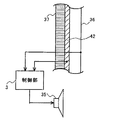
図1は、本発明の実施の形態1に係る騒音低減装置の構成を示す図である。図1において、騒音低減装置は、制御音源1と、誤差検出器2と、制御部3とを備える。騒音低減装置は、空間5を囲む壁面4に設置される。空間5は、騒音を低減する対象となる空間であり、空間5の外部に存在する騒音源からの騒音が漏れ込んでくる。ここで、空間5の外部から空間5の内部へ騒音が伝搬してくる経路を騒音伝搬経路と呼ぶ。騒音伝搬経路は、典型的には、壁面4が有する孔を通る経路である(図1に示す点線参照。)。ただし、壁面4の孔に限らず、壁面4の他の部分に比べて騒音が漏れ込みやすい部分があれば、当該部分を通る経路が騒音伝搬経路となり得る。例えば、図1に示す壁面4および空間5が一般的な建築物における部屋であり、その部屋に窓が設けられている場合を想定すると、騒音伝搬経路は窓を通る経路となると考えられる。
(Embodiment 1)
FIG. 1 is a diagram showing a configuration of a noise reduction apparatus according to
図1において、制御音源1は、上記騒音伝搬経路をふさぐように設置される。具体的には、壁面4には孔が設けられており、制御音源1は当該孔をふさぐように設置される。換言すれば、壁面4の孔は制御音源1を取り付けるための孔である。制御音源1は、空間5内の騒音を打ち消すためのスピーカである。誤差検出器2は、空間5内に設置される。誤差検出器2は、音を検出するためのマイクである。制御部3は、制御音源1および誤差検出器2に接続される。制御部3の設置位置は、空間5内部であってもよいし、空間5外部であってもよい。また、壁面4の内部に設けられてもよい。
In FIG. 1, the control sound
次に、実施の形態1に係る騒音低減装置の動作を説明する。なお、以下の説明においては、壁面4によって囲まれた空間5には、制御音源1が設置される孔から騒音が漏れ込み、他の部分から騒音が漏れ込むことはないものとする。また、空間5内の音は外部から漏れ込んでくる騒音に起因する音のみであるとする。図1において、誤差検出器2は、空間5内の音を検出する。検出結果は、誤差信号として制御部3へ出力される。制御部3は、誤差信号に基づいて、制御音源1を制御するための制御信号を制御音源1へ出力する。具体的には、空間5内の音(騒音)が0になるように、すなわち、誤差信号が0となるように、制御音源1を制御する。より具体的には、誤差検出器2の位置における騒音と逆位相かつ同音圧となる音を制御音源1に発生させるように制御する。この結果、制御音源1は、騒音伝搬経路を通って空間5内へ伝搬される騒音を打ち消すように動作する。
Next, the operation of the noise reduction device according to
制御部3の動作を詳細に説明する。図1において、誤差検出器2位置での騒音をN、制御音源1から誤差検出器2までの伝達関数をCとすると、制御部3の特性は、−1/Cとなるように設定されればよい。これによって、制御音源1から放射された制御音は、誤差検出器2の位置において、
N・(−1/C)・C=−N
となる。騒音と制御音源1による制御音とは互いに干渉し、誤差検出器2の位置において、
N+(−N)=0
となる。以上のように騒音と制御音とを干渉させることによって、誤差検出器2の位置における騒音を低減することができる。
The operation of the
N · (−1 / C) · C = −N
It becomes. The noise and the control sound from the control sound
N + (− N) = 0
It becomes. As described above, the noise at the position of the
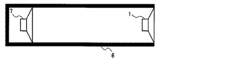
また、制御音源1は騒音伝搬経路上に騒音を遮蔽するように設置されるので、制御音源1自身が遮音部材として機能する。図2は、制御音源1の遮音部材としての機能を測定するための装置を示す図である。図2において、当該装置は、制御音源1と、音響管6と、騒音用スピーカ7とを備える。この装置は、口径10cmの音響管6の内部の一方の端部(開口していない)に騒音用スピーカ7を設置し、他方の端部(開口している)に口径7cmの動電型スピーカを制御音源1として設置したものである。なお、音響管6は、騒音用スピーカ7によって発生された音が制御音源1の設置部分以外の部分から漏れないようにするために設けられる。この装置において、騒音用スピーカ7を駆動させ(制御音源1のスピーカは駆動させない)、制御音源1を設置した音響管6の端部から10cm離れた点を観測点として音の挿入損失を測定する。
Further, since the control sound
図3は、図2に示す装置において測定された挿入損失を示す図である。図3は、図2に示す装置において制御音源1のスピーカを音響管6に挿入しなかった場合に対して制御音源1のスピーカを挿入した場合に、音の損失がどれだけあるかを示すグラフである。図3に示されるように、制御音源1を挿入することによって、音響管6から放射する騒音は、観測した全周波数帯域において低減している。また、100(Hz)から1(kHz)での平均挿入損失として−12.1(dB)が得られた。なお、周波数によって挿入損失に差があるのは、制御音源1を音響管6の端部に設置することによって音響管6の内部に音響モードが発生することが原因である。以上のように、制御音源1を騒音伝搬経路上に騒音を遮蔽するように設置することによって、制御音源1自体が騒音を遮音することがわかる。すなわち、実施の形態1に係る騒音低減装置によれば、壁面4の透過音を能動的に低減することに加え、制御音源1自身が遮音部材として機能するので、より一層の遮音性能を得ることが可能になる。
FIG. 3 is a diagram showing insertion loss measured in the apparatus shown in FIG. FIG. 3 is a graph showing how much sound is lost when the speaker of the control sound
また、図1に示す騒音低減装置では、騒音は制御音源1を透過して空間5に伝搬される。具体的には、騒音は、制御音源1であるスピーカの振動板の振動によって空間5に伝搬される。一方、騒音を低減するために制御音源1が発生する制御音も騒音と同様、スピーカの振動板の振動によって空間5に伝搬される。従って、制御音源1を透過して空間5に伝搬される騒音は、音の波面が制御音と近似することとなる。これによって、本発明に係る騒音低減装置では、空間5における広範囲のエリアにわたって騒音を低減することが可能となる。以下、詳細を説明する。
In the noise reduction apparatus shown in FIG. 1, the noise is transmitted through the control sound
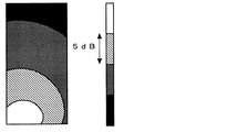
図4は、騒音と制御音との波面の近似性を測定するための装置を示す図である。図4に示す装置は、制御音源1と、誤差検出器2aおよび2bと、騒音用スピーカ7と、防音箱8と、比較用音源9とを備える。この装置は、1辺30(cm)の立方体である防音箱8のある1面に騒音用スピーカ7を設置し、当該面と反対側の面に制御音源1を設置したものである。制御音源1は、騒音伝搬経路上の位置、すなわち、防音箱8の孔の位置に、当該孔をふさぐように設置される。一方、比較用音源9は、騒音伝搬経路上でない位置、すなわち、防音箱8の孔以外の位置に設置される。防音箱8は、騒音用スピーカ7によって発生された音(騒音)が制御音源1を介してのみ防音箱8の外部に伝搬するように設置される。誤差検出器2aおよび2bは、騒音を低減するための動作を行うために用いられる。誤差検出器2aは、防音箱8の中心から前方(図4における上方)鉛直方向に20(cm)離れた位置に設置される。誤差検出器2bは、防音箱8の中心から前方鉛直方向に5(cm)離れた位置に設置される。図4に示す装置において、騒音用スピーカ7、制御音源1のスピーカまたは比較用音源9のスピーカを駆動させた場合の解析結果を、図5〜図10に示す。また、騒音を打ち消すために制御音源1を駆動させた場合の解析結果と、騒音を打ち消すために比較用音源9を駆動させた場合の解析結果とを、図11〜図13に示す。なお、図4に示す点線は、図5〜図13において示される観測範囲を示す。
FIG. 4 is a diagram showing an apparatus for measuring the closeness of the wavefront between noise and control sound. The apparatus shown in FIG. 4 includes a
図5は、図4に示す装置において騒音用スピーカ7を駆動させた場合における観測範囲の音圧分布を示す図である。また、図6は、図4に示す装置において制御音源1のスピーカを駆動させた場合における観測範囲の音圧分布を示す図であり、図7は、図4に示す装置において比較用音源9のスピーカを駆動させた場合における観測範囲の音圧分布を示す図である。図5および図6から明らかなように、騒音用スピーカ7を駆動させた場合と、制御音源1のスピーカを駆動させた場合との音圧分布は非常に似た特性となっている。一方、図7によれば、比較用音源9のスピーカを駆動させた場合の音圧分布は、騒音用スピーカ7を駆動させた場合および制御音源1のスピーカを駆動させた場合とは異なる特性となっていることがわかる。
FIG. 5 is a diagram showing the sound pressure distribution in the observation range when the noise speaker 7 is driven in the apparatus shown in FIG. 6 is a diagram showing the sound pressure distribution in the observation range when the speaker of the control sound
図8は、図4に示す装置において、騒音用スピーカ7を駆動させた場合における観測範囲の位相分布を示す図である。また、図9は、図4に示す装置において制御音源1のスピーカを駆動させた場合における観測範囲の位相分布を示す図であり、図10は、図4に示す装置において比較用音源9のスピーカを駆動させた場合における観測範囲の位相分布を示す図である。図8〜図10によれば、位相分布についても音圧分布と同様、騒音用スピーカ7を駆動させた場合と、制御音源1のスピーカを駆動させた場合との音圧分布は非常に似た特性となっていることがわかる。さらに、比較用音源9のスピーカを駆動させた場合の音圧分布は、それらのスピーカを駆動させた場合とは異なる特性となっていることがわかる。
FIG. 8 is a diagram showing the phase distribution of the observation range when the noise speaker 7 is driven in the apparatus shown in FIG. 9 is a diagram showing the phase distribution of the observation range when the speaker of the control sound
図5〜図10によれば、制御音と騒音との音の波面が近似することがわかる。従って、本発明によれば、広範囲にわたって制御音と騒音とを逆位相かつ同音圧とすることが可能であり、それ故、広範囲にわたって騒音低減効果を得ることが可能である。以下、図11〜図13を用いて詳細を説明する。 5 to 10, it can be seen that the wave fronts of the control sound and the noise are approximate. Therefore, according to the present invention, it is possible to make the control sound and the noise have opposite phases and the same sound pressure over a wide range, and therefore, it is possible to obtain a noise reduction effect over a wide range. Details will be described below with reference to FIGS.
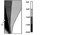
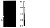
図11は、図4に示す装置において比較用音源9を用いた場合における騒音低減効果を示す図である。図11では、図4に示す構成要素のうち、騒音用スピーカ7による騒音を低減するために比較用音源9および誤差検出器2aが用いられる。具体的には、誤差検出器2aの位置における騒音ができるだけ小さくなるように比較用音源9を駆動させる。一方、図12は、図4に示す装置において制御音源1を用いた場合における騒音低減効果を示す図である。図12では、図4に示す構成要素のうち、騒音用スピーカ7による騒音を低減するために制御音源1および誤差検出器2aが用いられる。具体的には、誤差検出器2aの位置における騒音ができるだけ小さくなるように制御音源1を駆動させる。
FIG. 11 is a diagram showing the noise reduction effect when the
図11を見ると、比較用音源9を用いた場合には、誤差検出器2aの近傍のエリアや、比較用音源9から誤差検出器2aの設置された位置への方向に伸びるエリアについては高い騒音低減効果を得ることができるが、その他のエリアについては騒音低減効果を得ることができないことがわかる。これは、比較用音源9による音と騒音との波面が異なることから、比較用音源9による音は、誤差検出器2aの位置で騒音と逆位相かつ同音圧となっても、その他の位置では必ずしも騒音と逆位相かつ同音圧とならないことが原因である。一方、図12を見ると、制御音源1を用いた場合には、ほとんどの観測範囲において高い騒音低減効果を得ることができることがわかる。これは、制御音と騒音との波面が近似することから、制御音が誤差検出器2aの位置で騒音と逆位相かつ同音圧となれば、その他の位置でも騒音と逆位相かつ同音圧となるからである。
Referring to FIG. 11, when the
また、図13は、図12と同様、図4に示す装置において制御音源1を用いた場合における騒音低減効果を示す図である。ただし、図13は、誤差検出器2bを用いている点で図12と異なっている。つまり、図13は、誤差検出器2bの位置における騒音ができるだけ小さくなるように制御音源1を駆動させることによって得られた結果である。図13から明らかなように、制御音源1を用いる場合には、誤差検出器の設置位置を変更しても、ほぼ同様の騒音低減効果を得ることができる。
13 is a diagram showing the noise reduction effect when the control sound
以上のように、本発明によれば、広帯域の騒音を防止するために重量の大きい材質によって構成する必要がないので、軽量な騒音低減装置を実現することができる。さらに、制御音源1による制御音によって騒音を打ち消すので、騒音の周波数によらず、広帯域にわたって騒音低減効果を得ることができる。さらに、騒音伝搬経路をふさぐように制御音源1を設置することによって、制御音と騒音との波面を近似させることができる。これによって、騒音を低減する対象となる空間の広範囲にわたって高い騒音低減効果を得ることができる。
As described above, according to the present invention, since it is not necessary to use a heavy material in order to prevent broadband noise, a lightweight noise reduction device can be realized. Furthermore, since the noise is canceled by the control sound from the control sound
さらに、実施の形態1によれば、誤差検出器の位置が制限されないという利点がある。すなわち、比較用音源9を用いて騒音を低減する場合には、誤差検出器の設置位置付近のみにおいて高い騒音低減効果が現れることから、騒音を低減したい位置に誤差検出器を設置しなければならないという制限があった。これに対して、実施の形態1によれば、誤差検出器の位置にかかわらず広範囲にわたって高い騒音低減効果が現れるので、誤差検出器の設置位置が制限されない。従って、実施の形態1に係る騒音低減装置は、比較用音源9を用いる装置に比べて、設計の自由度が高いと言える。
Furthermore, according to the first embodiment, there is an advantage that the position of the error detector is not limited. That is, when noise is reduced using the
また、実施の形態1によれば誤差検出器の位置を自由に選択可能であることから、誤差検出器を制御音源の近傍に設置することも可能である。誤差検出器を制御音源の近傍に設置することによって、騒音を低減したい空間の音響特性の変化(例えば人や物品の位置の変化、温度変化など)が制御音源から誤差検出器までの伝達関数に与える影響を小さくすることができる。従って、実施の形態1によれば、誤差検出器を制御音源の近傍に設置することによって、騒音を低減したい空間の音響特性が変化しても高い騒音低減効果を得ることが可能である。 Further, according to the first embodiment, since the position of the error detector can be freely selected, the error detector can be installed in the vicinity of the control sound source. By installing an error detector in the vicinity of the control sound source, changes in the acoustic characteristics of the space where noise is desired to be reduced (for example, changes in the position of people and objects, temperature changes, etc.) The influence given can be reduced. Therefore, according to the first embodiment, by installing the error detector in the vicinity of the control sound source, it is possible to obtain a high noise reduction effect even if the acoustic characteristics of the space where noise is desired to be changed are changed.
なお、実施の形態1では、誤差検出器2の誤差信号に基づいて制御信号を生成するフィードバックシステムを制御部3として用いた。ここで、他の実施形態においては、騒音低減装置は、フィードフォワードシステムを制御部3として用いるものであっても構わない。例えば、騒音低減装置は、図14に示す構成であってもよい。図14は、実施の形態1に係る騒音低減装置の変形例を示す図である。図14に示す騒音低減装置は、図1に示す構成要素に加え、騒音検出器10をさらに備えている。騒音検出器10は、空間5の外部に設置され、騒音を検出する。このとき、制御部3は、誤差検出器2および騒音検出器10の検出結果に基づいて制御信号を生成する。
In the first embodiment, a feedback system that generates a control signal based on the error signal of the
図15は、図14に示す制御部3の詳細な構成の一例を示す図である。図15において、制御部3は、FXフィルタ11と、係数更新器12と、適応フィルタ13とを備えている。FXフィルタ11は、騒音検出器10から出力される信号を入力する。FXフィルタ11の特性は、制御音源1から誤差検出器2までの伝達関数と同等な特性を有するように設定される。係数更新器12は、誤差検出器2の出力信号を誤差入力として入力するとともに、FXフィルタ11から出力される信号を基準入力として入力する。適応フィルタ13は、係数更新器12から出力される信号と騒音検出器10から出力される信号とを入力し、制御信号を出力する。
FIG. 15 is a diagram illustrating an example of a detailed configuration of the
図15において、係数更新器12は、LMS(Least Mean Square)アルゴリズム等によって、基準入力と相関のある誤差入力が常に小さくなるように適応フィルタ13のフィルタ係数を更新する演算を行う。そして、演算結果に従って適応フィルタ13のフィルタ係数を更新する。適応フィルタ13は更新されたフィルタ係数に従って制御信号を生成し、生成した制御信号を制御音源1へ出力する。
In FIG. 15, the
以下、図15における制御部3の動作をより具体的に説明する。ここで、誤差検出器2の位置での騒音をN、制御音源1から誤差検出器2までの伝達関数をCとする。このとき、FXフィルタ11の特性はCに設定される。係数更新器12が適応フィルタ13を収束させることによって、誤差検出器2の出力信号における騒音成分は0に近づく。このとき、適応フィルタ13は−1/Cの特性に収束する。すなわち、適応フィルタ13の出力は、N・(−1/C)となる。従って、制御音源1による制御音は、誤差検出器2の位置において、N・(−1/C)・Cとなるので、誤差検出器2で検出される騒音Nは、当該制御音と合成され、
N+N・(−1/C)・C=0
となる。以上によって、誤差検出器2において騒音が低減されることがわかる。
Hereinafter, the operation of the
N + N · (−1 / C) · C = 0
It becomes. From the above, it can be seen that noise is reduced in the
なお、制御部3は、誤差検出器2において検出される音ができるだけ小さくなるように制御音源1を制御するものであれば、どのような構成であっても構わない。制御部3は、図15においては適応フィルタを用いたデジタル処理を行ったが、アナログ回路によって構成されてもよい。
The
なお、実施の形態1において、制御音源1は上述した動電型のスピーカの他、圧電素子を用いた圧電スピーカやその他の方式のスピーカであってもよい。例えば、加振器を設置した板を振動させることによって音を放射するスピーカを制御音源とした場合についても同様な騒音低減効果が得られることは言うまでもない。
In the first embodiment, the control sound
なお、実施の形態1において、騒音伝搬経路として複数の経路が考えられる場合には、各騒音伝搬経路について寄与率(空間5内に伝搬してくる騒音のうち、その経路によって伝搬されてくる騒音の割合を示す指標)を算出してもよい。この場合、最も寄与率が高い騒音伝搬経路をふさぐように制御音源を設置することが好ましい。 In the first embodiment, when a plurality of paths are considered as the noise propagation paths, the contribution ratio (the noise propagated through the path among the noises propagated in the space 5) for each noise propagation path. May be calculated). In this case, it is preferable to install the control sound source so as to block the noise propagation path having the highest contribution rate.
(実施の形態2)
次に、実施の形態2に係る騒音低減装置について説明する。なお、実施の形態1に係る騒音低減装置は、壁面の孔に制御音源(スピーカ)を設置するという方法であった。そのため、実施の形態1をそのまま実現すると、例えば部屋の壁面にスピーカが設置されているような構成となり、見た目の違和感をユーザに抱かせてしまうおそれがある。そこで、実施の形態2では、本発明の動作原理を応用して、より現実に即した構成とした騒音低減装置を提案する。
(Embodiment 2)
Next, a noise reduction device according to
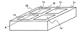
図16は、実施の形態2に係る騒音低減装置の概観図である。図16に示す騒音低減装置は1つのセルを単位とし、このセルを複数並べて配置することによって遮音パネルを構成する。遮音パネルは、個別に作成されたセルを接着することによって形成されてもよいし、複数のセルを一体的に作成することによって形成されてもよい。実施の形態2では、この遮音パネルを壁面に設置することによって、壁面によって囲まれた空間内の騒音を低減する。図17は、図16に示すセルを並べた場合における断面を示す図である。なお、図17は、図16に示すA−Bを断面とした場合の断面図である。
FIG. 16 is an overview of the noise reduction device according to the second embodiment. The noise reduction apparatus shown in FIG. 16 has a single cell as a unit, and a plurality of cells are arranged side by side to constitute a sound insulation panel. The sound insulation panel may be formed by adhering individually created cells, or may be formed by integrally creating a plurality of cells. In
図16および図17において、セル20は、4つのスピーカ1a〜1dと、誤差検出器2と、制御部3と、筐体21とを備えている。実施の形態2においては、制御音源は、4つのスピーカ1a〜1dによって構成される。ここでは、スピーカ1a〜1dは圧電スピーカであるとする。なお、実施の形態1と同一の構成要素には同一の符号を付してその説明を省略する。以下の各実施の形態においても同様とする。
16 and 17, the
図16および図17において、筐体21は、直方体の1面にスピーカ1a〜1dを設置するための孔が設けられた構成である。なお、以下の説明においては、筐体21の各面のうち、スピーカ1a〜1dが設置される面を上面と呼ぶ。上面の反対側の面は開口しており、開口している部分が壁面22に接着される。また、上面および上面に反対側の面以外の面を側面と呼ぶ。スピーカ1a〜1dは、筐体21の上面に設けられた孔に設置される。つまり、実施の形態2においては、制御音源は筐体21によって壁面22に取り付けられる。制御音源を構成する各スピーカ1a〜1dは、それぞれ、実施の形態1の制御音源1と同様の部材を用いることができる。図16においては、制御音源を構成するスピーカは4つであるが、スピーカの数はいくつであっても構わない。誤差検出器2は、筐体21の内部に設置される。制御部3は、任意の位置に設置される。
16 and 17, the
図17に示されるように、筐体の側面が他の筐体の側面と接続されることによってセルが接続され、それによって遮音パネルが構成される。筐体の側面には、隣接するセルとの間における制御音の干渉を防止するための遮音仕切が設けられる。筐体を壁面に設置すると、筐体と壁面22との間に騒音低減用の空間が形成される。遮音パネルは、筐体の上面が騒音源に向くように壁面22に設置される。つまり、図17においては、騒音を低減する対象となる空間は、壁面22の右側の空間である。
As shown in FIG. 17, cells are connected by connecting a side surface of a housing to a side surface of another housing, thereby forming a sound insulation panel. A sound insulation partition for preventing interference of control sound between adjacent cells is provided on the side surface of the housing. When the housing is installed on the wall surface, a noise reduction space is formed between the housing and the
次に、実施の形態2に係る騒音低減装置の動作を説明する。筐体21を実施の形態1における壁面4とみなし、セル20と壁面22によって囲まれる空間を実施の形態1における空間5とみなせば、実施の形態2に係る騒音低減装置の動作は実施の形態1と同様である。すなわち、スピーカ1a〜1dおよび筐体21を透過してセルの内部に伝搬した騒音に対してスピーカ1a〜1dから発生される制御音を作用させる。このとき、誤差検出器2は筐体21内の誤差音を検出し、誤差信号として制御部3へ出力する。制御部3は誤差信号に基づいて制御信号を生成し、各スピーカ1a〜1dへ出力する。より具体的には、図17において、誤差検出器2位置での騒音をNa、各スピーカ1a〜1dから誤差検出器2までの伝達関数をCaとする(ここでは、4つのスピーカ1a〜1dから誤差検出器2までの伝達関数をすべて同じであるとみなす。)と、制御部3の特性は、−1/Caとなるように設定されればよい。これによって、制御音源から放射された制御音は、誤差検出器2の位置において、
Na・(−1/Ca)・Ca=−Na
となる。騒音と制御音源による制御音とは互いに干渉し、誤差検出器2の位置において、
Na+(−Na)=0
となる。以上のように騒音と制御音とを干渉させることによって、誤差検出器2の位置における騒音を低減することができる。また、実施の形態1と同様、誤差検出器2の位置のみならず、セル20内の空間のほとんどすべての位置において騒音を低減することができる。
Next, the operation of the noise reduction device according to
Na. (-1 / Ca) .Ca = -Na
It becomes. The noise and the control sound from the control sound source interfere with each other, and at the position of the
Na + (− Na) = 0
It becomes. As described above, the noise at the position of the
次に、複数のセルを並べて接続することによって遮音パネルを構成した場合(図17参照)を考える。この場合、あるセルの制御音源によって発生された制御音が隣のセルに影響を及ぼす可能性が考えられる。そこで、実施の形態2においては、筐体21を、遮音仕切の役割を果たす側面を有する構成としている。側面を設けることによって、各セルが騒音を低減するための空間をそれぞれ有する構成とする。これによって、制御音が隣のセルに伝搬することを防止するのである。このような構成にすることによって、各セルの制御部の設計において、隣のセルの制御音の影響を考慮する必要がなくなる。従って、実施の形態2によれば、制御部を簡易な回路で構成することができるという利点がある。以下、この利点について図18を用いて詳細を説明する。
Next, consider a case where a sound insulation panel is configured by connecting a plurality of cells side by side (see FIG. 17). In this case, there is a possibility that the control sound generated by the control sound source of a certain cell affects the adjacent cell. Therefore, in the second embodiment, the
図18は、実施の形態2において、遮音仕切を設けることによる隣のセルへの遮音効果を示す図である。図18は、図17に示す装置において、あるセルの制御音源から発生する音を当該セルの誤差検出器で検出したレベルと当該セルの隣のセルの誤差検出器で検出したレベルとの差(図18に示すゲイン)を示す。また、図18に示す実線は遮音仕切(筐体の側面)がある場合を示し、点線は遮音仕切がない場合を示す。なお、図18においては、制御音源を構成する4つのスピーカはそれぞれ60mm角の圧電スピーカであり、それらの中心から壁面22の方向へ10(mm)離れた場所に誤差検出器が配置されているものとする。また、壁面22は厚さ0.5(mm)の鉄板で構成され、遮音仕切は厚さ4(mm)、高さ8(mm)、長さ100(mm)の樹脂材で構成されているものとする。
FIG. 18 is a diagram showing a sound insulation effect on an adjacent cell by providing a sound insulation partition in the second embodiment. FIG. 18 shows a difference between the level detected by the error detector of the cell and the level detected by the error detector of the cell adjacent to the cell in the apparatus shown in FIG. (Gain shown in FIG. 18). Moreover, the solid line shown in FIG. 18 shows the case where there is a sound insulation partition (side surface of the housing), and the dotted line shows the case where there is no sound insulation partition. In FIG. 18, each of the four speakers constituting the control sound source is a 60 mm square piezoelectric speaker, and an error detector is disposed at a location 10 (mm) away from the center of the speaker in the direction of the
図18から明らかなように、遮音仕切を設けた場合、2つの誤差検出器(制御音が発生しているセルの誤差検出器およびその隣のセルの誤差検出器)の音圧レベル差は、250(Hz)から1(kHz)までの広い周波数範囲で大きくなっている。なお、一般的に、図18に示すゲインが−10(dB)よりも小さければ(すなわち、音圧レベル差が10(dB)よりも大きければ)、隣のセルへほとんど影響を与えないと考えられる。従って、遮音仕切を設けることによってほぼすべての周波数範囲で隣のセルへの影響をなくすことができると言える。なお、遮音仕切を設けた場合において200(Hz)付近で音圧レベル差が小さくなっているのは、200(Hz)程度の周波数において壁面22が共振しているからである。壁面22が共振する周波数は、セルによって壁面が区切られる大きさや壁面22の材質等に起因する。一方、遮音仕切がない場合、2つの誤差検出器の音圧レベル差は遮音仕切がある場合に比べて小さくなっている。つまり、遮音仕切がない場合、あるセルの制御音源から発生した制御音が隣接するセルの誤差検出器に混入していることがわかる。
As is apparent from FIG. 18, when the sound insulation partition is provided, the sound pressure level difference between the two error detectors (the error detector of the cell generating the control sound and the error detector of the adjacent cell) is It is large in a wide frequency range from 250 (Hz) to 1 (kHz). In general, if the gain shown in FIG. 18 is smaller than −10 (dB) (that is, if the sound pressure level difference is larger than 10 (dB)), it is considered that the adjacent cells are hardly affected. It is done. Therefore, it can be said that the influence on the adjacent cell can be eliminated in almost all frequency ranges by providing the sound insulation partition. In the case where the sound insulation partition is provided, the sound pressure level difference is small in the vicinity of 200 (Hz) because the
次に、隣のセルからの制御音が誤差検出器に混入する場合における制御部の制御について考える。ここでは、セルAの制御音源による制御音がセルBに与える影響を考える。あるセルBにおいて、誤差検出器の位置での騒音をNb、制御音源から誤差検出器までの伝達関数をCbとする。制御部の特性を−1/Cbとすると、制御音源から放射された制御音は、誤差検出器の位置において、
Nb・(−1/Cb)・Cb=−Nb
となる。誤差検出器の位置において、騒音と制御音とは互いに干渉し、
Nb+(−Nb)=0
となる。以上は上述した通りである。ここで、当該セルBに隣接するセルAの制御音源を動作させた場合を考える。セルAの制御音の誤差検出器(セルB)への伝搬量をDaとする。この場合、セルBの誤差検出器の位置では、騒音と、セルBの制御音源による制御音と、セルAの制御音源の制御音とは互いに干渉する。従って、セルBの誤差検出器の位置における音は、
Nb+(−Nb)+Da=Da
となる。つまり、セルAからの制御音の誤差検出器(セルB)への伝搬音Daが残留騒音となる。従って、隣接するセルAの制御音源からの制御音がセルBの誤差検出器に混入することによって、騒音低減効果が悪化することになる。ここで、残留騒音Daを低減するためには、セルBの制御部の特性を−(Nb+Da)/Cbとする必要があり、残留騒音を0とした場合に比べて特性が複雑になってしまう。さらに、セルBの制御音源の制御音はセルAの誤差検出器にも伝搬することを考慮すると、セルAおよびセルBの誤差検出器の双方で良好な騒音低減効果を得ようとすれば、制御部の特性は非常に複雑になってしまう。また、ここでは2つのセルが隣接する場合について示したが、隣接するセルの数が増えれば、制御部の特性がより一層複雑になる。
Next, the control of the control unit when the control sound from the adjacent cell is mixed in the error detector will be considered. Here, the influence of the control sound by the control sound source of cell A on cell B is considered. In a certain cell B, the noise at the position of the error detector is Nb, and the transfer function from the control sound source to the error detector is Cb. When the characteristic of the control unit is -1 / Cb, the control sound emitted from the control sound source is at the position of the error detector.
Nb · (−1 / Cb) · Cb = −Nb
It becomes. Noise and control sound interfere with each other at the position of the error detector,
Nb + (− Nb) = 0
It becomes. The above is as described above. Here, consider a case where the control sound source of the cell A adjacent to the cell B is operated. Let Da be the amount of propagation of the control sound of cell A to the error detector (cell B). In this case, at the position of the error detector of cell B, the noise, the control sound from the control sound source of cell B, and the control sound of the control sound source of cell A interfere with each other. Therefore, the sound at the position of the error detector in cell B is
Nb + (− Nb) + Da = Da
It becomes. That is, the propagation sound Da from the cell A to the error detector (cell B) of the control sound becomes residual noise. Therefore, the control sound from the control sound source of the adjacent cell A is mixed into the error detector of the cell B, so that the noise reduction effect is deteriorated. Here, in order to reduce the residual noise Da, it is necessary to set the characteristic of the control unit of the cell B to − (Nb + Da) / Cb, and the characteristic becomes more complicated than when the residual noise is set to zero. . Furthermore, considering that the control sound of the control sound source of the cell B is also propagated to the error detector of the cell A, if an attempt is made to obtain a good noise reduction effect in both the error detectors of the cell A and the cell B, The characteristics of the control unit are very complicated. Although the case where two cells are adjacent to each other is shown here, the characteristics of the control unit become more complicated as the number of adjacent cells increases.
以上のことから、遮音仕切を設けない場合には、制御部の特性が非常に複雑になり、制御部の設計が困難になる。これに対して、実施の形態2では、遮音仕切を用いることによって、隣接するセルの制御音源から伝搬する制御音を低減している。これによって、制御部の特性は自己のセルの制御音源から誤差検出器までの伝達関数に基づいて設定することができるので、制御部の構成を簡易にすることができる。さらに、残留騒音が少なくなるなるので、良好な騒音低減効果を得ることができる。
From the above, when the sound insulation partition is not provided, the characteristics of the control unit become very complicated, and the design of the control unit becomes difficult. On the other hand, in
以上に説明したように、実施の形態2においては、各筐体と壁面22との間に騒音低減用の空間が形成され、この空間において騒音が低減される。その結果、壁面22には騒音が伝搬しないので、壁面22に面する空間(図17に示す壁面22の右側の空間)には、騒音が伝搬しない。従って、図17に示す遮音パネルを用いることによって騒音を低減することができる。
As described above, in the second embodiment, a noise reduction space is formed between each housing and the
以上のように、実施の形態2によれば、騒音低減装置を壁面22に設置することによって、壁面22によって囲まれる内部の空間における騒音を低減することができるので、実施の形態1と同様の効果を得ることができる。さらに、実施の形態1に係る騒音低減装置は壁面に設けられた孔に設置しなければならないという制限があったのに対して、実施の形態2に係る騒音低減装置はそのような制限がない。従って、実施の形態2に係る騒音低減装置は、実施の形態1と比べて設置が容易であり、実現が容易である。例えば、部屋の壁面に遮音パネルを設置することによって、部屋内に伝搬してくる騒音を低減することができる。
As described above, according to the second embodiment, by installing the noise reduction device on the
なお、実施の形態2では、誤差検出器から出力される誤差信号に基づいて制御信号を生成するフィードバックシステムを制御部の制御回路として用いる場合について示した。ここで、実施の形態2に係る騒音低減装置に実施の形態1で示したような騒音検出器をさらに設け、騒音検出器と誤差検出器との出力信号に基づいて制御信号を生成する既知のフィードフォワードシステムを制御回路として用いても、良好な騒音低減効果が得られることは言うまでもない。なお、この点については後述する実施の形態3〜5についても同様である。 In the second embodiment, the case where the feedback system that generates the control signal based on the error signal output from the error detector is used as the control circuit of the control unit has been described. Here, a noise detector as shown in the first embodiment is further provided in the noise reduction apparatus according to the second embodiment, and a known control signal is generated based on output signals from the noise detector and the error detector. It goes without saying that even if the feedforward system is used as a control circuit, a good noise reduction effect can be obtained. This also applies to Embodiments 3 to 5 described later.
(実施の形態3)
次に、実施の形態3に係る騒音低減装置について説明する。なお、実施の形態2に係る騒音低減装置では、壁面22が共振する周波数において遮音仕切の遮音効果が小さくなっていた(図18参照)。実施の形態3に係る騒音低減装置は、このような周波数においても遮音仕切の遮音効果を向上するものである。
(Embodiment 3)
Next, a noise reduction device according to
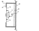
図19は、実施の形態3に係る騒音低減装置であるセルを並べた場合における断面を示す図である。図19に示すセル23は、図17に示すセル20が備える構成要素に加えて、支柱24をさらに備えている。なお、その他の構成要素についてはセル20と同様であるので、同一の参照符号を付し詳細な説明を省略する。支柱24は、遮音仕切によって区切られた壁面22の各部分の中央付近(重心付近)に接続されるように設けられる。
FIG. 19 is a diagram illustrating a cross-section when cells that are noise reduction apparatuses according to
実施の形態3に係る騒音低減装置の動作は、実施の形態2に係る騒音低減装置の動作と同様である。ここで、実施の形態3においては、支柱24は、壁面22の振動を抑制する振動抑制手段としての役割を果たす。これによって、壁面22の振動が低減するので、あるセルからの制御音が壁面22の振動を経て隣接するセルの誤差検出器に伝搬することを防止することができる。
The operation of the noise reduction device according to the third embodiment is the same as the operation of the noise reduction device according to the second embodiment. Here, in the third embodiment, the
図20は、実施の形態3において、支柱を設けることによる隣のセルへの遮音効果を示す図である。図20は、図19に示す装置において、あるセルの制御音源から発生する音を当該セルの誤差検出器で検出したレベルと当該セルの隣のセルの誤差検出器で検出したレベルとの差(図20に示すゲイン)を示す。また、図20に示す実線は支柱がある場合を示し、点線は支柱がない場合を示す。なお、図20においては、支柱は、直径5(mm)の金属棒であり、筐体21の上面の中心と遮音仕切によって区切られた壁面22の各部分の中心とを連結するように設置されるものとする。なお、それ以外の条件は、図18に示す条件と同じである。
FIG. 20 is a diagram illustrating a sound insulation effect on an adjacent cell by providing a support in the third embodiment. FIG. 20 shows the difference between the level detected by the error detector of the cell and the level detected by the error detector of the cell next to the cell in the apparatus shown in FIG. The gain shown in FIG. Moreover, the solid line shown in FIG. 20 shows the case where there is a support, and the dotted line shows the case where there is no support. In FIG. 20, the support pillar is a metal bar having a diameter of 5 (mm), and is installed so as to connect the center of the upper surface of the
図20に示されるように、振動抑制手段として支柱を設けることによって、振動抑制手段がないときには音圧レベル差が5(dB)程度しかなかった200(Hz)において、20(dB)の音圧レベル差を得ることができることがわかる。また、300(Hz)〜550(Hz)において支柱を設けない場合に比べて音圧レベル差は減少するものの、100(Hz)〜1(kHz)の全周波数帯域において少なくとも10(dB)の音圧レベル差があることがわかる。 As shown in FIG. 20, by providing a column as vibration suppression means, when there is no vibration suppression means, the sound pressure level is 20 (dB) at 200 (Hz) where the difference in sound pressure level was only about 5 (dB). It can be seen that a level difference can be obtained. In addition, although the difference in sound pressure level is reduced compared to the case where no support is provided in 300 (Hz) to 550 (Hz), at least 10 (dB) sound in the entire frequency band from 100 (Hz) to 1 (kHz). It can be seen that there is a pressure level difference.
上述したように、実施の形態2に係る騒音低減装置において200(Hz)の周波数帯域で隣のセルへの遮音効果が小さくなるのは、あるセルにおいて発生された制御音が壁面22を介して隣のセルに伝搬することが原因である。詳細に説明すると、実施の形態2では、壁面22がセルの大きさに分割される(実施の形態2では、100(mm)角の正方形に分割される)結果、壁面22は制御音によって200(Hz)前後の周波数で大きく振動することとなる。そして、この振動が周囲の隣接するセルに伝搬し、隣接するセルの誤差検出器では壁面22からの2次放射による放射音が検出されるのである。なお、このとき、壁面22において最も振動が大きいのは、各セルの遮音仕切によって区切られた壁面22の各部分の重心付近である。
As described above, in the noise reduction apparatus according to the second embodiment, the sound insulation effect on the adjacent cell is reduced in the frequency band of 200 (Hz) because the control sound generated in a certain cell passes through the
一方、実施の形態3では、振動抑制手段によって壁面22の振動が抑制されるので、周囲への振動の伝搬も低減され、その振動が原因で隣接するセルの誤差検出器に伝搬する音も低減されることになる。その結果、隣のセルへの遮音効果をさらに向上することができるので、騒音低減装置の遮音性能をさらに向上することができる。
On the other hand, in the third embodiment, the vibration of the
また、実施の形態3においては、誤差検出器2を支柱24に接続することによって、誤差検出器2をセル23の内部に容易に設置することができる。
In the third embodiment, the
なお、実施の形態3では、振動抑制手段として支柱を設置した場合について説明したが、振動抑制手段は必ずしもこのような形態である必要はなく、遮音仕切によって区切られた壁面の各部分の重心付近の振動を抑制する効果が得られるものであればどのような手段であってもよい。例えば、図21に示すように、錘を振動抑制手段として用いてもよい。図21は、実施の形態3に係る騒音低減装置の変形例を示す図である。なお、図21においては、セル1つ分のみを図示している。図21においては、セル23は、支柱に代えて錘25を備えている。錘25は、遮音仕切によって区切られた壁面22の各部分の重心付近に設置される。この錘25よっても、壁面22の振動を抑制することができ、支柱を設けた場合と同様の効果を得ることができる。
In the third embodiment, the case where a column is installed as the vibration suppressing means has been described. However, the vibration suppressing means is not necessarily in such a form, and the vicinity of the center of gravity of each part of the wall surface partitioned by the sound insulating partition. Any means may be used as long as the effect of suppressing the vibration is obtained. For example, as shown in FIG. 21, a weight may be used as vibration suppressing means. FIG. 21 is a diagram illustrating a modification of the noise reduction device according to the third embodiment. FIG. 21 shows only one cell. In FIG. 21, the
(実施の形態4)
次に、実施の形態4に係る騒音低減装置について説明する。なお、前述の実施の形態2および3では、壁面の凹凸が原因で、各セルの制御部の特性を一定にすることができないおそれがあった(詳細は後述する)。実施の形態4は、各セルの制御部の特性を一定にすることを可能とし、それによって制御部の設計作業を容易にするものである。
(Embodiment 4)
Next, a noise reduction device according to
図22は、実施の形態4に係る騒音低減装置であるセルの断面を示す図である。なお、図22においては、1つ分のセル26のみを図示している。図22において、セル26は、図17に示すセル20が備える構成要素に加えて、膜27をさらに備えている。なお、その他の構成要素についてはセル20と同様であるので、同一の参照符号を付し詳細な説明を省略する。膜27は、セル26の上面の反対側に設けられる開口部をふさぐように設けられる。この膜27と、スピーカ1a〜1dと、筐体21とによって、閉空間が形成される。
FIG. 22 is a diagram illustrating a cross section of a cell which is a noise reduction device according to the fourth embodiment. In FIG. 22, only one
実施の形態4に係る騒音低減装置の動作は、実施の形態2に係る騒音低減装置の動作と同様である。従って、制御音源から誤差検出器までの伝達関数をCとすれば、制御部3の特性は、上述したように、−1/Cとする必要がある。つまり、正確に制御を行うためには、この伝達関数Cを正確に把握することが好ましい。
The operation of the noise reduction device according to the fourth embodiment is the same as the operation of the noise reduction device according to the second embodiment. Therefore, if the transfer function from the control sound source to the error detector is C, the characteristic of the
一方、実施の形態2以降において説明したセルを用いて騒音を低減する場合、複数のセルが必要になる。従って、各セルの制御部について上記の伝達関数を調べ、設定する必要がある。ここで、各セルの制御部の伝達関数は、セルの取り付け状態、すなわち、壁面22の凹凸が原因で、セル毎に異なる特性となる場合がある。
On the other hand, when noise is reduced using the cells described in the second and subsequent embodiments, a plurality of cells are required. Therefore, it is necessary to examine and set the transfer function for the control unit of each cell. Here, the transfer function of the control unit of each cell may have different characteristics for each cell due to the cell attachment state, that is, the unevenness of the
図23は、膜27のないセルを壁面に取り付けた場合における伝達関数を示す図である。図23は、壁面の異なる3箇所(取り付け箇所1〜3)に同一のセルを取り付け、その伝達関数を観測した結果である。セルは同一であるので、本来、伝達関数は同一になるはずであるが、図23に示す観測結果では、特に700(Hz)以下の周波数帯域で大きく異なる特性となっている。これは、壁面22に凹凸があるために壁面22と筐体21との取り付け状態がセル毎に異なってしまうことが原因である。すなわち、壁面22に凹凸があるために取り付け場所によって筐体21と壁面22との間に隙間が生じるからである。この隙間が各セルによって異なるので、スピーカ1a〜1dと筐体21と壁面22とによって構成される空間の密閉度が各セルによって異なることとなり、そのため、スピーカ1a〜1dによって構成される制御音源のインピーダンスが変化してしまう。以上の理由で、各セルによって伝達関数が異なってしまうのである。
FIG. 23 is a diagram illustrating a transfer function when a cell without the
このように伝達関数Cがセル毎に異なる場合、セルを壁面22に取り付けた後、セル毎に伝達関数Cを調整しなければならず、設定作業が煩雑になる。また、この場合、すべてのセルについて一定の伝達関数を設定すると、各セルについて正確な伝達関数を設定したことにならず、各セルの制御音源を正確に制御することができない。
As described above, when the transfer function C is different for each cell, the transfer function C must be adjusted for each cell after the cell is attached to the
そこで、実施の形態4においては、セル26に膜27を設けることによって、セル26の内部に閉空間を形成する。図24は、膜27を有するセルを壁面に取り付けた場合における伝達関数を示す図である。図24は、図23と同様、壁面の異なる3箇所(取り付け箇所1〜3)に同一のセルを取り付け、その伝達関数を観測した結果である。なお、ここでは、膜27は、厚さ0.1(mm)の樹脂フィルムとする。なお、取り付ける面の材質、位置は図23で示した条件と同一であるとする。図23では、3つの伝達関数が特に700(Hz)以下の周波数帯域で大きく異なっていたのに対して、図24では、100(Hz)〜1(kHz)の全ての周波数帯域で3つの伝達関数が類似した特性となっている。これは、膜27によってセル内に構成される空間の密閉度が一定になったことが理由である。また、当該空間が形成されることによって、筐体21と壁面22との取り付け状態が伝達関数に与える影響が低減したことが理由である。
Therefore, in the fourth embodiment, a closed space is formed inside the
以上のように、実施の形態4によれば、壁面22と筐体21との取り付け状態が伝達関数に与える影響が低減されるので、各セルの伝達関数をほぼ一定にすることができる。従って、各セルの制御部において一定の特性を設定することができ、各制御部の設定作業が容易になる。
As described above, according to the fourth embodiment, since the influence of the attachment state of the
なお、実施の形態4では膜を用いる場合について説明したが、膜を用いる代わりに、板状の部材や他の形態の部材を用いてセル内の空間の密閉度を一定にしても、実施の形態4と同様の効果が得られることは言うまでもない。すなわち、セル内に閉空間を形成する閉空間形成手段は、膜状の部材であっても板状の部材であっても構わない。 In the fourth embodiment, the case where a film is used has been described. However, instead of using a film, a plate-like member or another type of member may be used to make the sealing degree of the space in the cell constant. Needless to say, the same effect as in the fourth aspect can be obtained. That is, the closed space forming means for forming the closed space in the cell may be a film-like member or a plate-like member.
なお、実施の形態4に係る騒音低減装置は、実施の形態4に示す構成に加えて、さらに実施の形態3の構成を備えるようにしてもよい。すなわち、実施の形態4に係る騒音低減装置は、図19に示す支柱24または図21に示す錘25をさらに備えていてもよい。これによって、実施の形態4において説明した効果に加え、実施の形態3において説明した効果を得ることができる。
Note that the noise reduction device according to the fourth embodiment may further include the configuration of the third embodiment in addition to the configuration shown in the fourth embodiment. That is, the noise reduction device according to the fourth embodiment may further include the
(実施の形態5)
次に、実施の形態5に係る騒音低減装置について説明する。なお、実施の形態2〜4においては、制御部3の設置位置は任意であった。これに対して、実施の形態5に係る騒音低減装置は、制御部3の設置位置を特定するものである。
(Embodiment 5)
Next, a noise reduction device according to
図25は、実施の形態5に係る騒音低減装置であるセルの断面を示す図である。なお、図25においては、1つ分のセル28のみを図示している。実施の形態5に係る騒音低減装置は、実施の形態4に係る騒音低減装置と同様の構成要素を有するが、制御部3がセル28の内部に設置される点で異なっている。すなわち、制御部3は、スピーカ1a〜1dと、筐体21と、膜27とによって構成される閉空間の内部に配置される。なお、実施の形態5に係る騒音低減装置の動作は、実施の形態4に係る騒音低減装置の動作と同様である。
FIG. 25 is a diagram illustrating a cross section of a cell which is a noise reduction device according to the fifth embodiment. In FIG. 25, only one
図25に示す構成によって、騒音低減装置は次のような利点を有する。すなわち、制御部3は上記閉空間の内部に設置されるので、塵や水滴等から制御部3を保護することができる。実際に使用する際においては、制御部3を塵や水滴等から保護するケースが必要となると考えられるが、実施の形態5によれば、そのようなケースを用意することなく、制御部3の耐候性を向上することができる。さらに、制御部3を閉空間の内部に設置することによって、誤差検出器2と制御部3との設置位置が近接することとなる。そのため、誤差検出器2から出力される誤差信号を制御部3へ入力する間に混入する電気ノイズを低減することができ、より正確な制御を行うことができる。
With the configuration shown in FIG. 25, the noise reduction device has the following advantages. That is, since the
なお、上記図25においては、騒音低減装置は膜27を備える構成であったが、膜27を備えていない構成であっても上記と同様の効果を得ることができる。また、実施の形態5に係る騒音低減装置は、実施の形態5に示す構成に加えて、さらに実施の形態3の構成を備えるようにしてもよい。これによって、実施の形態5において説明した効果に加え、実施の形態3において説明した効果を得ることができる。
In FIG. 25, the noise reduction device has the configuration including the
なお、上記実施の形態2〜5においては、セル内部に形成される空間の音を誤差検出器2を用いて検出した。ここで、他の実施の形態においては、セルが接続される壁面の振動を検出することによって音を検出するようにしてもよい。具体的には、振動を検出する振動検出手段をセルが接続される壁面に設置し、振動検出手段の検出結果に基づいて制御部による制御を行うようにしてもよい。また、誤差検出器2を用いる場合であっても、壁面に近接した位置に誤差検出器2を配置することによって、誤差検出器2に振動検出手段の役割を持たせることができる。
In the second to fifth embodiments, the sound in the space formed inside the cell is detected using the
(実施の形態6)
次に、実施の形態6に係る騒音低減装置について説明する。実施の形態6に係る騒音低減装置は、実施の形態2〜5とは異なる形態で、実施の形態1の動作原理を応用したものである。
(Embodiment 6)
Next, a noise reduction device according to Embodiment 6 will be described. The noise reduction device according to the sixth embodiment is different from the second to fifth embodiments, and applies the operation principle of the first embodiment.
図26は、実施の形態6に係る騒音低減装置の構成を示す図である。図26において、騒音低減装置は、制御音源1と、誤差検出器2と、制御部3とを備える。また、騒音低減装置は、騒音を低減する対象となる空間を囲む壁面4に設置され、壁面4における騒音伝搬経路上の孔をふさぐように設置される。以上の点については、実施の形態1と同様である。
FIG. 26 is a diagram illustrating the configuration of the noise reduction device according to the sixth embodiment. In FIG. 26, the noise reduction device includes a
実施の形態6が実施の形態1と異なる点は、制御音源1の構成である。図26において、制御音源1は、ドライバ35と、膜36と、基板37とを備えている。基板37は、壁面4に接続される。基板37は、壁面4と別体によって構成されてもよいし、壁面4と一体的に構成(すなわち、壁面4の一部が基板37の役割を果たす)されてもよい。ドライバ35は、基板37に設置される。膜36は、基板37に対して騒音源と反対側に設置される。膜36は、基板37との間に空気層38を形成するように配置される。実施の形態6では、膜36をドライバ35によって振動させることによって音を放射するスピーカを制御音源1として用いる。
The difference between the sixth embodiment and the first embodiment is the configuration of the control sound
次に、実施の形態6に係る騒音低減装置の動作を説明する。実施の形態6においては、騒音源からの騒音は、制御音源1のドライバ35および基板37を透過し膜36を振動させる。この振動によって壁面4の内部の空間に音が放射され、誤差検出器2に騒音が伝搬する。一方、ドライバ35が駆動することによって、空気層38の空気圧が加減圧され、膜36が振動する。この振動によって壁面4の内部の空間に制御音が放射される。
Next, the operation of the noise reduction device according to Embodiment 6 will be described. In the sixth embodiment, the noise from the noise source passes through the
誤差検出器2および制御部3の動作は、実施の形態1と同様である。すなわち、誤差検出器2は誤差信号を制御部3へ出力する。制御部3は、誤差検出器2からの誤差信号に基づいて、誤差検出器2において検出される騒音ができるだけ小さくなるようにドライバ35を制御する。
The operations of the
図26においては、制御部3は、FXフィルタ31と、FBフィルタ32と、係数更新器33と、適応フィルタ34とを備えている。FXフィルタ31は、誤差検出器2から出力される誤差信号を入力する。FXフィルタ31は、ドライバ35から誤差検出器2までの伝達関数と同等な特性を有する。FBフィルタ32は、適応フィルタ34から出力される制御信号を入力する。FBフィルタ32は、FXフィルタ31と同様の特性、すなわち、ドライバ35から誤差検出器2までの伝達関数と同等な特性を有する。係数更新器33は、誤差検出器2から出力される誤差信号と、FXフィルタ31から出力される信号とを入力する。適応フィルタ34は、係数更新器33から出力される信号と、誤差検出器2から出力される誤差信号とを入力する。そして、入力した信号に基づいて、ドライバ35に制御信号を出力する。
In FIG. 26, the
図26に示す制御部3においては、誤差検出器2から出力された誤差信号からFBフィルタ32から出力される信号が減算され、減算された結果がFXフィルタ31と係数更新器33と適応フィルタ34とに対して出力される。係数更新器33は、FXフィルタ31から出力される信号を基準入力として入力する。さらに、係数更新器33は、LMSアルゴリズム等によって、基準入力と相関のある誤差入力が常に小さくなるように適応フィルタ34のフィルタ係数を更新する演算を行う。そして、演算結果に従って適応フィルタ34のフィルタ係数を更新する。適応フィルタ34は更新されたフィルタ係数に従って制御信号を生成し、生成した制御信号をドライバ35へ出力する。ここで、ドライバ35から誤差検出器2までの伝達関数をCとした場合、FXフィルタ31およびFBフィルタ32の特性をCに設定する。このように設定されたFBフィルタ32によって、一巡信号による発振を生じることなく、適応フィルタ34を収束させることができる。最終的に、誤差検出器2によって検出される騒音に相当する信号は0に近づき、誤差検出器2を設置した点近傍の騒音が低減されることになる。
In the
なお、図26においては、制御部3の詳細な構成としてFXフィルタ31、FBフィルタ32、係数更新器33、および適応フィルタ34を用いた構成を示したが、制御部3の構成は、誤差検出器2において検出される音ができるだけ小さくなるようにドライバ35を制御するものであれば、どのような構成であっても構わない。
In FIG. 26, the detailed configuration of the
以上、実施の形態6に示したように、本発明は、ドライバ35によって膜36を振動させる形態のスピーカを制御音源として利用することができる。この場合においても、実施の形態1と同様の効果を得ることができる。なお、実施の形態6に示すスピーカは、例えばガラス窓を用いた構成とすることができる(後述する実施の形態9参照)。それによって、壁面に設置されても違和感のない騒音低減装置を実現することができる。
As described above, as shown in the sixth embodiment, the present invention can use a speaker having a form in which the
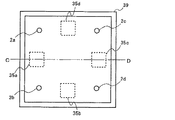
次に、実施の形態6のスピーカによって騒音を低減することができることを検証する。図27および図28は、実施の形態6における騒音低減効果を検証するために構築した効果検証システムを示す図である。図27は効果検証システムの垂直断面図であり、図28は効果検証システムを上方(図27における上方向)から見たときの平面図を示す。なお、図27は、図28に示すC−D断面の断面図である(誤差検出器2a〜2dは、C−D断面上に存在しないが、発明の理解を容易にするために図示している。)。
Next, it is verified that noise can be reduced by the speaker of the sixth embodiment. 27 and 28 are diagrams showing an effect verification system constructed to verify the noise reduction effect in the sixth embodiment. FIG. 27 is a vertical sectional view of the effect verification system, and FIG. 28 is a plan view of the effect verification system as viewed from above (the upward direction in FIG. 27). 27 is a cross-sectional view of the CD cross section shown in FIG. 28 (the
図27および図28に示す効果検証システムは、4つのドライバ35a〜35dと、4つの誤差検出器2a〜2dと、制御部3と、膜36と、防音箱39と、騒音信号源40と、騒音用スピーカ41とを備えている。防音箱39は、側面および底面が遮音性能の高い材料で構成されている。この防音箱39の上面にドライバ35a〜35dを設置する。さらに、ドライバ35a〜35dが設置された上側に膜36を設置する。防音箱39は上面が開口部を有しており、膜36は、開口部をふさいで防音箱39の内部が閉空間を形成するように設置される。そして、防音箱39の底面に設置した騒音用スピーカ41を騒音信号源40によって駆動することによって騒音を放射する。4つの誤差検出器2a〜2dは、ドライバ35a〜35dが設置された防音箱39の上面を透過する騒音を検出する。制御部3は、4つの誤差検出器2a〜2dの検出結果に基づいて、4つのドライバ35a〜35dを駆動させることによって、騒音を低減する。
The effect verification system shown in FIGS. 27 and 28 includes four
以下、上記の効果検証システムを用いて観測した観測結果を図29〜図38に示す。ここで、図29〜図35、および図37は、防音箱39を横方向から見た(図27と同じ向きから見た)分布を示す。一方、図36および図38は、防音箱39を上方向から見た(図28と同じ向きから見た)分布を示す。また、図29〜図35、および図37に分布が示される長方形は、横29(cm)×縦32(cm)である。一方、図36および図38に分布が示される長方形は、横29(cm)×縦29(cm)である。
The observation results observed using the above effect verification system are shown in FIGS. Here, FIGS. 29 to 35 and FIG. 37 show distributions of the
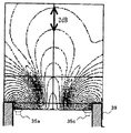
図29は、効果検証システムの上方における騒音(騒音用スピーカ41によって発生される音)の音圧分布を示す図である。また、図30は、効果検証システムの上方における騒音の位相分布を示す図である。図29および図30では、騒音用スピーカ41のみを駆動させ、制御音源であるドライバ35a〜35dは駆動させていない。図29および図30に示されるように、騒音に関しては音圧および位相の分布の双方共に、効果検証システム上面の中央付近を中心に同心円状の分布が見られる。
FIG. 29 is a diagram showing a sound pressure distribution of noise (sound generated by the noise speaker 41) above the effect verification system. FIG. 30 is a diagram showing the noise phase distribution above the effect verification system. 29 and 30, only the
図31は、膜36を設けた場合における、効果検証システムの上方における制御音(ドライバ35a〜35dによって発生される音)の音圧分布を示す図である。図32は、膜36を設けた場合における、効果検証システムの上方における制御音の位相分布を示す図である。図31および図32では、制御音源であるドライバ35a〜35dのみを駆動させ、騒音用スピーカ41は駆動させていない。図31および図32に示されるように、膜36を設けた場合には、制御音の音圧および位相分布は、騒音の音圧および位相分布と近似した分布が見られる。
FIG. 31 is a diagram illustrating a sound pressure distribution of control sounds (sounds generated by the
図33は、膜36を設けない場合における、効果検証システムの上方における制御音の音圧分布を示す図である。図34は、膜36を設けない場合における、効果検証システムの上方における制御音の位相分布を示す図である。図33および図34では、制御音源であるドライバ35a〜35dのみを駆動させ、騒音用スピーカ41は駆動させていない。図33および図34から、膜36を設けない場合には、制御音の音圧および位相分布は、騒音の音圧および位相分布とは異なる分布となることがわかる。
FIG. 33 is a diagram showing the sound pressure distribution of the control sound above the effect verification system when the
図35および図36は、膜36を設けた場合における、効果検証システムの上方における騒音低減効果の分布を示す図である。図35および図36は、騒音用スピーカ41を駆動させるとともに、誤差検出器2a〜2dで検出される音ができるだけ小さくなるようにドライバ35a〜35dが駆動された場合における騒音低減効果を示す。図35および図36から、膜36を設けた場合には、効果検証システムの上方のほとんどの空間において、15(dB)以上の騒音低減効果が得られていることがわかる。
FIG. 35 and FIG. 36 are diagrams showing the distribution of the noise reduction effect above the effect verification system when the
図37および図38は、膜36を設けない場合における、効果検証システムの上方における騒音低減効果の分布を示す図である。図37および図38は、図35および図36と同様、騒音用スピーカ41を駆動させるとともに、誤差検出器2a〜2dで検出される音ができるだけ小さくなるようにドライバ35a〜35dが駆動された場合における騒音低減効果を示す。図37および図38から、膜36を設けない場合には、誤差検出器2a〜2dの近傍でのみしか、十分な騒音低減効果が得られないことがわかる。
FIGS. 37 and 38 are diagrams illustrating the distribution of the noise reduction effect above the effect verification system when the
以上に示したように、膜36を設けることによって、誤差検出器の近傍のみならず、より広い範囲で十分な騒音低減効果を得ることができる。
As described above, by providing the
なお、実施の形態6においては、膜36を用いる構成を説明したが、ドライバによって振動させる振動部材は、透明膜に限らない。振動部材は、基板との間に空気層を有するように、かつ、当該空気層に放射される音によって振動可能なように設置されるものであればよい。例えば、透明な板を膜36の代わりに用い、弾性体により構成されるサスペンションによって基板と当該板を接続する。このような構成によって、板をドライバによって振動可能とすることができ、板を振動部材として用いることができる。
Although the configuration using the
(実施の形態7)
次に、実施の形態7に係る騒音低減装置について説明する。実施の形態7に係る騒音低減装置は、制御部においてフィードフォワード制御を行うようにしたものである。
(Embodiment 7)
Next, a noise reduction device according to Embodiment 7 will be described. In the noise reduction device according to the seventh embodiment, feedforward control is performed in the control unit.
図39は、実施の形態7に係る騒音低減装置の構成を示す図である。図39において、騒音低減装置は、実施の形態6に係る騒音低減装置の構成要素に加え、騒音検出器10を備えている。なお、騒音検出器10は、図16に示すものと同様である。また、制御部3の構成は、図16に示す構成と同様である。従って、実施の形態7の詳細な動作の説明は省略する。
FIG. 39 is a diagram illustrating the configuration of the noise reduction device according to the seventh embodiment. In FIG. 39, the noise reduction apparatus includes a
以上のように、膜をドライバによって振動させるスピーカを制御音源として用いる場合においても、制御部3においてフィードフォワード制御を行うことが可能である。これによって、ドライバをより正確に制御することができる。また、実施の形態7においても、実施の形態6と同様の効果を得ることができる。
As described above, even when a speaker that vibrates the membrane by a driver is used as a control sound source, the
(実施の形態8)
次に、実施の形態8に係る騒音低減装置について説明する。実施の形態8に係る騒音低減装置は、空間に伝搬する音を膜の振動によって検出するものである。
(Embodiment 8)
Next, a noise reduction apparatus according to
図40は、実施の形態8に係る騒音低減装置の構成を示す図である。なお、実施の形態8に係る騒音低減装置の全体構成は、実施の形態6と同様である。従って、図40では、実施の形態6と相違する部分を主に図示している。図40において、騒音低減装置は、図26に示す構成に加えて、背電極42を備えている。また、騒音低減装置は、誤差検出器2を備えていない。背電極42は、基板37において膜36が位置する側に設置される。
FIG. 40 is a diagram illustrating the configuration of the noise reduction device according to the eighth embodiment. The overall configuration of the noise reduction apparatus according to the eighth embodiment is the same as that of the sixth embodiment. Therefore, in FIG. 40, the part which is different from Embodiment 6 is mainly illustrated. In FIG. 40, the noise reduction apparatus includes a
実施の形態8においては、膜36を帯電させておき、膜36と背電極42との間に静電気を蓄えることによってコンデンサーを形成する。なお、実施の形態8においては、膜36は、ポリプロピレンやテフロン(R)系、ポリエチレン系等の高分子材料の膜の両面に正負の電荷が永久的に現れるエレクトレット材料を用いることが好ましい。以上のような構成にすることによって、膜36が振動して膜36と背電極42との距離が変化すると、コンデンサーの静電容量が変化し、膜36の振動を示す信号が制御部3へ出力されることになる。この信号が上記の誤差信号に対応する。以上のように、膜36の振動を検出することによって、空間に放射される音を検出することが可能である。なお、制御部3やドライバ35の動作は実施の形態6において説明した動作と同様である。
In the eighth embodiment, a capacitor is formed by charging the
以上のように、実施の形態8によれば、誤差検出器2によって音の音圧および位相を検出することに代えて、膜36の振動を検出することによって、空間に放射される音を検出する構成を用いる。この構成によっても、実施の形態6と同様の効果を得ることができる。
As described above, according to the eighth embodiment, instead of detecting the sound pressure and phase of the sound by the
また、膜36の振動自体を検出する構成としては、上記の他に、例えば図41に示す構成が考えられる。図41は、実施の形態8に係る騒音低減装置の変形例を示す図である。図41に示す騒音低減装置では、膜36の振動を検出して振動信号を出力する変換器43が用いられる。制御部3は、この振動信号を誤差信号として用いる。この構成によっても、実施の形態6と同様の効果を得ることができる。
In addition to the above, a configuration shown in FIG. 41, for example, can be considered as a configuration for detecting the vibration of the
また、図42は、実施の形態8に係る騒音低減装置の他の変形例を示す図である。実施の形態8においても、図42に示すように、他の実施の形態と同様、騒音検出器10をさらに備える構成としてもよい。
FIG. 42 is a diagram illustrating another modification of the noise reduction device according to the eighth embodiment. Also in the eighth embodiment, as shown in FIG. 42, the
(実施の形態9)
次に、実施の形態9に係る騒音低減装置について説明する。実施の形態9では、制御音源であるスピーカを、ガラス窓を利用して構成する。これによって、制御音源1を壁面4に設置することによる見た目の違和感を解消する。
(Embodiment 9)
Next, a noise reduction device according to
図43は、実施の形態9に係る騒音低減装置の構成を示す図である。図26において、騒音低減装置は、誤差検出器2と、制御部3と、ドライバ35と、サッシ44と、ガラス45と、透明膜46とを備えている。サッシ44は壁面4に取り付けられ、ガラス45はサッシ44に取り付けられている。透明膜46は、ガラス45に対して騒音源と反対側に配置される。透明膜46は、ガラス45との間に空気層47を形成するように配置される。ドライバ35は、空気層47へ音を放射するように、サッシ44の内部に設置される。
FIG. 43 is a diagram illustrating the configuration of the noise reduction device according to the ninth embodiment. In FIG. 26, the noise reduction device includes an
図43において、ガラス45およびサッシ44が図26に示す基板37に対応する。また、透明膜46は図26に示す膜36に対応する。従って、実施の形態9においては、ドライバ35と、サッシ44と、ガラス45と、透明膜46とによって制御音源が構成されている。つまり、制御音源であるスピーカが、ガラス窓を利用して構成されている。実施の形態9のスピーカは、実施の形態6と同様、ドライバ35が透明膜46を振動させることによって音を放射することが可能である。また、誤差検出器2および制御部3の動作は実施の形態6と同様である。以上より、実施の形態9に係る騒音低減装置は、実施の形態6に係る騒音低減装置と同様の動作を行うことが可能である。つまり、壁面4に設置されたガラス窓を用いる構成であっても、壁面4の内部において騒音を低減することが可能である。
43, the
以上のように、実施の形態9によれば、サッシ44およびガラス45を用いてスピーカを構成し、さらに、ドライバ35をサッシの内部に配置することによって、見た目の違和感をユーザに抱かせずに、騒音低減装置を設置することができる。また、膜は透明であるので、窓ガラスの採光や景観を損なうことがない。
As described above, according to the ninth embodiment, the speaker is configured using the
なお、実施の形態9においても、実施の形態7のようなフィードフォワード制御を行うことが可能である。また、実施の形態8のように、誤差検出器2に代えて、膜の振動を検出すること構成としてもよい。
In the ninth embodiment, it is possible to perform the feedforward control as in the seventh embodiment. Moreover, it is good also as a structure which replaces with the
本発明に係る騒音低減装置は、遮音部材として、または壁面を透過する騒音の低減装置等として利用することができる。また、制御点における音を低減する構成であるので、騒音のみならず音声信号であっても低減することが可能である。従って、音響特性調整装置等としても適応が可能である。 The noise reduction device according to the present invention can be used as a sound insulation member or a noise reduction device that transmits through a wall surface. Further, since the sound at the control point is reduced, it is possible to reduce not only noise but also a voice signal. Therefore, the present invention can also be applied as an acoustic characteristic adjusting device.
1 制御音源
2 誤差検出器
3 制御部
4 壁面
20 セル
21 筐体
24 支柱
25 錘
27,36 膜
35 ドライバ
37 基板
DESCRIPTION OF
Claims (14)
前記所定の空間の内外を分ける壁面に、騒音が伝搬してくる経路をふさぐように取り付けられ、かつ、前記壁面に対して前記所定の空間内へ音を放射するスピーカで構成される制御音源と、
前記騒音源から前記制御音源を介して伝搬してくる音を検出する音検出部と、
前記音検出部の検出結果に基づいて、当該音検出部によって検出される音ができるだけ
小さくなるように、前記制御音源に音を放射させる制御部とを備える、騒音低減装置。 A noise reduction device for reducing noise propagating from an external noise source into a predetermined space,
A wall separating the inside and outside of said predetermined space, mounted so as to close a path noise propagated through, and a control sound source a speaker that emits a sound to the predetermined space with respect to the wall surface ,
A sound detection unit for detecting sound propagating from the noise source via the control sound source;
A noise reduction device comprising: a control unit that radiates sound to the control sound source so that the sound detected by the sound detection unit becomes as small as possible based on the detection result of the sound detection unit.
空間を形成する筐体をさらに備え、
前記制御音源は、前記筐体によって前記壁面に取り付けられ、
前記音検出部は、前記騒音低減用の空間内に配置され、
前記制御音源は、前記騒音低減用の空間内へ音を放射する、請求項1に記載の騒音低減
装置。 A housing that is installed on a side where the noise source is present with respect to the wall surface, and that forms a noise reduction space between the wall surface and the wall surface;
The control sound source is attached to the wall surface by the housing,
The sound detection unit is disposed in the noise reduction space,
The noise reduction device according to claim 1, wherein the control sound source radiates sound into the noise reduction space.
前記壁面のうち、各前記筐体によって前記騒音低減用の空間に分けられた各部分におけ
る重心位置の振動を抑制する振動抑制部をさらに備える、請求項2に記載の騒音低減装置
。 The housing is a plurality, and is installed on the wall surface adjacent to each other,
The noise reduction device according to claim 2, further comprising: a vibration suppressing unit that suppresses vibration of a center of gravity position in each portion of the wall surface divided into the noise reduction space by each housing.
音低減装置。 The noise reduction device according to claim 3, wherein the vibration suppression unit is a support column that connects the housing and the wall surface.
置。 The noise reduction device according to claim 3, wherein the vibration suppression unit is a weight installed at the position of the center of gravity.
2に記載の騒音低減装置。 The noise reduction device according to claim 2, further comprising a membrane connected to the housing and making the noise reduction space a closed space.
装置。 The noise reduction device according to claim 2, wherein the control unit is disposed inside the noise reduction space.
前記制御部は、前記音検出部および前記騒音検出部の検出結果に基づいて、前記制御音
源を制御する、請求項1に記載の騒音低減装置。 A noise detection unit that is installed outside the predetermined space and detects noise;
The noise reduction device according to claim 1, wherein the control unit controls the control sound source based on detection results of the sound detection unit and the noise detection unit.
前記制御音源は、
前記孔をふさぐように前記壁面に接続される基板と、
前記基板との間に空気層を有するように、かつ、当該空気層に放射される音によって
振動可能なように、前記基板に対して前記所定の空間が存在する側に配置される振動部材
と、
前記空気層に音を放射するドライバとを含み、
前記制御部は、制御信号によって前記ドライバに音を放射させる、請求項1に記載の騒
音低減装置。 The wall is provided with holes,
The control sound source is
A substrate connected to the wall surface to block the hole;
A vibration member disposed on a side where the predetermined space exists with respect to the substrate so as to have an air layer between the substrate and the substrate so as to be vibrated by sound radiated to the air layer; ,
A driver for emitting sound to the air layer,
The noise reduction device according to claim 1, wherein the control unit causes the driver to emit sound according to a control signal.
音圧および位相を検出することによって当該音を検出する、請求項11に記載の騒音低減
装置。 The noise reduction according to claim 11, wherein the sound detection unit is disposed in the predetermined space and detects the sound by detecting a sound pressure and a phase of the sound propagating into the predetermined space. apparatus.
してくる音を検出する、請求項11に記載の騒音低減装置。 The noise reduction device according to claim 11, wherein the sound detection unit detects sound propagating into the predetermined space by detecting vibration of the vibration member.
騒音低減装置。 The noise reduction device according to claim 11, wherein the substrate and the vibration member are made of a transparent material.
Priority Applications (1)
| Application Number | Priority Date | Filing Date | Title |
|---|---|---|---|
| JP2003322152A JP4086743B2 (en) | 2002-09-20 | 2003-09-12 | Noise control device |
Applications Claiming Priority (4)
| Application Number | Priority Date | Filing Date | Title |
|---|---|---|---|
| JP2002274538 | 2002-09-20 | ||
| JP2003099066 | 2003-04-02 | ||
| JP2003283742 | 2003-07-31 | ||
| JP2003322152A JP4086743B2 (en) | 2002-09-20 | 2003-09-12 | Noise control device |
Publications (3)
| Publication Number | Publication Date |
|---|---|
| JP2005062786A JP2005062786A (en) | 2005-03-10 |
| JP2005062786A5 JP2005062786A5 (en) | 2006-04-27 |
| JP4086743B2 true JP4086743B2 (en) | 2008-05-14 |
Family
ID=34382088
Family Applications (1)
| Application Number | Title | Priority Date | Filing Date |
|---|---|---|---|
| JP2003322152A Expired - Fee Related JP4086743B2 (en) | 2002-09-20 | 2003-09-12 | Noise control device |
Country Status (1)
| Country | Link |
|---|---|
| JP (1) | JP4086743B2 (en) |
Families Citing this family (7)
| Publication number | Priority date | Publication date | Assignee | Title |
|---|---|---|---|---|
| DE102005016021A1 (en) * | 2005-04-07 | 2006-10-12 | Airbus Deutschland Gmbh | Active counter sound system has secondary actuators arranged at edge of open depressing surface to be penetrable by primary sound wave |
| JP4769043B2 (en) * | 2005-08-01 | 2011-09-07 | 公益財団法人鉄道総合技術研究所 | Noise vibration reduction device |
| US8116472B2 (en) * | 2005-10-21 | 2012-02-14 | Panasonic Corporation | Noise control device |
| JP2010176100A (en) * | 2009-02-02 | 2010-08-12 | Tottori Univ | Active lightweight sound isolation unit |
| US8705760B2 (en) | 2009-05-12 | 2014-04-22 | Panasonic Corporation | Active noise control device |
| CN102449688A (en) * | 2010-03-26 | 2012-05-09 | 松下电器产业株式会社 | Speaker device, audio control device, wall attached with speaker device |
| CN113611277B (en) * | 2021-08-09 | 2024-04-23 | 安徽聆思智能科技有限公司 | Noise reduction method, noise reduction device and noise reduction system |
-
2003
- 2003-09-12 JP JP2003322152A patent/JP4086743B2/en not_active Expired - Fee Related
Also Published As
| Publication number | Publication date |
|---|---|
| JP2005062786A (en) | 2005-03-10 |
Similar Documents
| Publication | Publication Date | Title |
|---|---|---|
| US10349166B2 (en) | Passive acoustic radiator module | |
| US5692053A (en) | Active acoustic transmission loss box | |
| JP5562860B2 (en) | Active noise control device | |
| CN101147189A (en) | Active countersound system with special arrangement of the secondary actuators for reducing the passage of sound at an open boundary area of two volumes | |
| JP2012198407A (en) | Panel speaker | |
| JPWO2009144818A1 (en) | Speaker system | |
| JP2008534991A (en) | Active noise control method and apparatus using film speaker | |
| EP1400950A2 (en) | Noise reduction apparatus performing active noise control | |
| JP4086743B2 (en) | Noise control device | |
| JP4120649B2 (en) | Soundproofing device | |
| US20100266138A1 (en) | Device and method for active sound damping in a closed interior space | |
| WO2011039842A1 (en) | Sound reproducing device | |
| US8985287B2 (en) | Device for actively influencing vibrations in a component | |
| CA2112368C (en) | Noise control device | |
| JP4561429B2 (en) | Intake system sound propagation structure | |
| JP5641726B2 (en) | Active vibration noise control device | |
| JP2004216971A (en) | Active noise reduction device for rolling stock | |
| JPH03228097A (en) | Vibration controller | |
| JP2005003777A (en) | Sound absorption system | |
| JPH0836392A (en) | Device and method for sound insulation of wall body | |
| JP5310112B2 (en) | Flat speaker | |
| JP4769043B2 (en) | Noise vibration reduction device | |
| JPH06318083A (en) | Active muffler device | |
| JPH08314471A (en) | Muffler | |
| JPH07302089A (en) | Electronic muffler system |
Legal Events
| Date | Code | Title | Description |
|---|---|---|---|
| A521 | Request for written amendment filed |
Free format text: JAPANESE INTERMEDIATE CODE: A523 Effective date: 20060308 |
|
| A621 | Written request for application examination |
Free format text: JAPANESE INTERMEDIATE CODE: A621 Effective date: 20060308 |
|
| A131 | Notification of reasons for refusal |
Free format text: JAPANESE INTERMEDIATE CODE: A131 Effective date: 20071116 |
|
| A521 | Request for written amendment filed |
Free format text: JAPANESE INTERMEDIATE CODE: A523 Effective date: 20071227 |
|
| TRDD | Decision of grant or rejection written | ||
| A01 | Written decision to grant a patent or to grant a registration (utility model) |
Free format text: JAPANESE INTERMEDIATE CODE: A01 Effective date: 20080125 |
|
| A61 | First payment of annual fees (during grant procedure) |
Free format text: JAPANESE INTERMEDIATE CODE: A61 Effective date: 20080219 |
|
| FPAY | Renewal fee payment (event date is renewal date of database) |
Free format text: PAYMENT UNTIL: 20110228 Year of fee payment: 3 |
|
| R150 | Certificate of patent or registration of utility model |
Ref document number: 4086743 Country of ref document: JP Free format text: JAPANESE INTERMEDIATE CODE: R150 Free format text: JAPANESE INTERMEDIATE CODE: R150 |
|
| FPAY | Renewal fee payment (event date is renewal date of database) |
Free format text: PAYMENT UNTIL: 20120229 Year of fee payment: 4 |
|
| FPAY | Renewal fee payment (event date is renewal date of database) |
Free format text: PAYMENT UNTIL: 20130228 Year of fee payment: 5 |
|
| FPAY | Renewal fee payment (event date is renewal date of database) |
Free format text: PAYMENT UNTIL: 20130228 Year of fee payment: 5 |
|
| FPAY | Renewal fee payment (event date is renewal date of database) |
Free format text: PAYMENT UNTIL: 20140228 Year of fee payment: 6 |
|
| LAPS | Cancellation because of no payment of annual fees |