EP2244101A1 - System und verfahren zur erkennung, ortung und identifizierung von objekten über dem boden und unter dem boden in einem vorreferenzierten interessensbereich - Google Patents
System und verfahren zur erkennung, ortung und identifizierung von objekten über dem boden und unter dem boden in einem vorreferenzierten interessensbereich Download PDFInfo
- Publication number
- EP2244101A1 EP2244101A1 EP09700523A EP09700523A EP2244101A1 EP 2244101 A1 EP2244101 A1 EP 2244101A1 EP 09700523 A EP09700523 A EP 09700523A EP 09700523 A EP09700523 A EP 09700523A EP 2244101 A1 EP2244101 A1 EP 2244101A1
- Authority
- EP
- European Patent Office
- Prior art keywords
- ground
- locating
- detecting
- objects above
- identifying objects
- Prior art date
- Legal status (The legal status is an assumption and is not a legal conclusion. Google has not performed a legal analysis and makes no representation as to the accuracy of the status listed.)
- Withdrawn
Links
- 238000000034 method Methods 0.000 title claims abstract description 61
- 238000012545 processing Methods 0.000 claims abstract description 27
- 238000013500 data storage Methods 0.000 claims abstract description 5
- 230000035515 penetration Effects 0.000 claims abstract description 5
- 238000005259 measurement Methods 0.000 claims description 39
- 238000001514 detection method Methods 0.000 claims description 22
- 229910052751 metal Inorganic materials 0.000 claims description 10
- 239000002184 metal Substances 0.000 claims description 10
- 238000000280 densification Methods 0.000 claims description 8
- 238000004422 calculation algorithm Methods 0.000 claims description 7
- 230000008569 process Effects 0.000 claims description 5
- 239000013598 vector Substances 0.000 claims description 5
- 238000002156 mixing Methods 0.000 claims description 3
- 230000001360 synchronised effect Effects 0.000 claims description 3
- 230000001276 controlling effect Effects 0.000 claims 2
- 230000000875 corresponding effect Effects 0.000 claims 2
- 230000002596 correlated effect Effects 0.000 claims 1
- 230000000750 progressive effect Effects 0.000 abstract 1
- 239000002360 explosive Substances 0.000 description 11
- 230000008901 benefit Effects 0.000 description 6
- 238000005516 engineering process Methods 0.000 description 6
- 230000005540 biological transmission Effects 0.000 description 4
- 238000010586 diagram Methods 0.000 description 4
- 239000000463 material Substances 0.000 description 4
- 230000000149 penetrating effect Effects 0.000 description 4
- 239000002689 soil Substances 0.000 description 4
- 230000009466 transformation Effects 0.000 description 4
- 238000006243 chemical reaction Methods 0.000 description 3
- 238000013461 design Methods 0.000 description 3
- 230000003993 interaction Effects 0.000 description 3
- 238000004088 simulation Methods 0.000 description 3
- 230000003068 static effect Effects 0.000 description 3
- 238000013459 approach Methods 0.000 description 2
- 230000000295 complement effect Effects 0.000 description 2
- 238000012937 correction Methods 0.000 description 2
- 238000006073 displacement reaction Methods 0.000 description 2
- 230000005674 electromagnetic induction Effects 0.000 description 2
- 238000005286 illumination Methods 0.000 description 2
- 230000010354 integration Effects 0.000 description 2
- 238000000691 measurement method Methods 0.000 description 2
- 229910052755 nonmetal Inorganic materials 0.000 description 2
- 229920000515 polycarbonate Polymers 0.000 description 2
- 239000004417 polycarbonate Substances 0.000 description 2
- 230000005855 radiation Effects 0.000 description 2
- 238000011160 research Methods 0.000 description 2
- 239000011435 rock Substances 0.000 description 2
- UFHFLCQGNIYNRP-UHFFFAOYSA-N Hydrogen Chemical compound [H][H] UFHFLCQGNIYNRP-UHFFFAOYSA-N 0.000 description 1
- 238000012952 Resampling Methods 0.000 description 1
- 230000002159 abnormal effect Effects 0.000 description 1
- 229910052782 aluminium Inorganic materials 0.000 description 1
- XAGFODPZIPBFFR-UHFFFAOYSA-N aluminium Chemical compound [Al] XAGFODPZIPBFFR-UHFFFAOYSA-N 0.000 description 1
- 238000004458 analytical method Methods 0.000 description 1
- 238000004364 calculation method Methods 0.000 description 1
- 238000004140 cleaning Methods 0.000 description 1
- 238000004891 communication Methods 0.000 description 1
- 230000006835 compression Effects 0.000 description 1
- 238000007906 compression Methods 0.000 description 1
- 238000005094 computer simulation Methods 0.000 description 1
- 238000001816 cooling Methods 0.000 description 1
- 230000001419 dependent effect Effects 0.000 description 1
- 238000005474 detonation Methods 0.000 description 1
- 230000000694 effects Effects 0.000 description 1
- 238000002593 electrical impedance tomography Methods 0.000 description 1
- 230000005670 electromagnetic radiation Effects 0.000 description 1
- 238000001983 electron spin resonance imaging Methods 0.000 description 1
- 238000010438 heat treatment Methods 0.000 description 1
- 229910052739 hydrogen Inorganic materials 0.000 description 1
- 239000001257 hydrogen Substances 0.000 description 1
- 238000003384 imaging method Methods 0.000 description 1
- 238000007689 inspection Methods 0.000 description 1
- 238000009434 installation Methods 0.000 description 1
- 230000002452 interceptive effect Effects 0.000 description 1
- 150000002739 metals Chemical class 0.000 description 1
- 239000000203 mixture Substances 0.000 description 1
- 230000000422 nocturnal effect Effects 0.000 description 1
- 239000003973 paint Substances 0.000 description 1
- 239000000047 product Substances 0.000 description 1
- 239000002994 raw material Substances 0.000 description 1
- 230000008707 rearrangement Effects 0.000 description 1
- 238000005070 sampling Methods 0.000 description 1
- 230000011664 signaling Effects 0.000 description 1
- 239000004575 stone Substances 0.000 description 1
- 239000000126 substance Substances 0.000 description 1
- 239000013589 supplement Substances 0.000 description 1
- 230000002194 synthesizing effect Effects 0.000 description 1
- 238000000844 transformation Methods 0.000 description 1
- 238000002604 ultrasonography Methods 0.000 description 1
- 238000010200 validation analysis Methods 0.000 description 1
- 239000002699 waste material Substances 0.000 description 1
- XLYOFNOQVPJJNP-UHFFFAOYSA-N water Substances O XLYOFNOQVPJJNP-UHFFFAOYSA-N 0.000 description 1
Images



Classifications
-
- G—PHYSICS
- G01—MEASURING; TESTING
- G01V—GEOPHYSICS; GRAVITATIONAL MEASUREMENTS; DETECTING MASSES OR OBJECTS; TAGS
- G01V3/00—Electric or magnetic prospecting or detecting; Measuring magnetic field characteristics of the earth, e.g. declination, deviation
- G01V3/15—Electric or magnetic prospecting or detecting; Measuring magnetic field characteristics of the earth, e.g. declination, deviation specially adapted for use during transport, e.g. by a person, vehicle or boat
- G01V3/17—Electric or magnetic prospecting or detecting; Measuring magnetic field characteristics of the earth, e.g. declination, deviation specially adapted for use during transport, e.g. by a person, vehicle or boat operating with electromagnetic waves
-
- G—PHYSICS
- G01—MEASURING; TESTING
- G01C—MEASURING DISTANCES, LEVELS OR BEARINGS; SURVEYING; NAVIGATION; GYROSCOPIC INSTRUMENTS; PHOTOGRAMMETRY OR VIDEOGRAMMETRY
- G01C15/00—Surveying instruments or accessories not provided for in groups G01C1/00 - G01C13/00
-
- G—PHYSICS
- G01—MEASURING; TESTING
- G01S—RADIO DIRECTION-FINDING; RADIO NAVIGATION; DETERMINING DISTANCE OR VELOCITY BY USE OF RADIO WAVES; LOCATING OR PRESENCE-DETECTING BY USE OF THE REFLECTION OR RERADIATION OF RADIO WAVES; ANALOGOUS ARRANGEMENTS USING OTHER WAVES
- G01S13/00—Systems using the reflection or reradiation of radio waves, e.g. radar systems; Analogous systems using reflection or reradiation of waves whose nature or wavelength is irrelevant or unspecified
- G01S13/88—Radar or analogous systems specially adapted for specific applications
- G01S13/885—Radar or analogous systems specially adapted for specific applications for ground probing
-
- G—PHYSICS
- G01—MEASURING; TESTING
- G01S—RADIO DIRECTION-FINDING; RADIO NAVIGATION; DETERMINING DISTANCE OR VELOCITY BY USE OF RADIO WAVES; LOCATING OR PRESENCE-DETECTING BY USE OF THE REFLECTION OR RERADIATION OF RADIO WAVES; ANALOGOUS ARRANGEMENTS USING OTHER WAVES
- G01S13/00—Systems using the reflection or reradiation of radio waves, e.g. radar systems; Analogous systems using reflection or reradiation of waves whose nature or wavelength is irrelevant or unspecified
- G01S13/88—Radar or analogous systems specially adapted for specific applications
- G01S13/89—Radar or analogous systems specially adapted for specific applications for mapping or imaging
-
- G—PHYSICS
- G01—MEASURING; TESTING
- G01S—RADIO DIRECTION-FINDING; RADIO NAVIGATION; DETERMINING DISTANCE OR VELOCITY BY USE OF RADIO WAVES; LOCATING OR PRESENCE-DETECTING BY USE OF THE REFLECTION OR RERADIATION OF RADIO WAVES; ANALOGOUS ARRANGEMENTS USING OTHER WAVES
- G01S19/00—Satellite radio beacon positioning systems; Determining position, velocity or attitude using signals transmitted by such systems
- G01S19/38—Determining a navigation solution using signals transmitted by a satellite radio beacon positioning system
- G01S19/39—Determining a navigation solution using signals transmitted by a satellite radio beacon positioning system the satellite radio beacon positioning system transmitting time-stamped messages, e.g. GPS [Global Positioning System], GLONASS [Global Orbiting Navigation Satellite System] or GALILEO
- G01S19/42—Determining position
- G01S19/43—Determining position using carrier phase measurements, e.g. kinematic positioning; using long or short baseline interferometry
Definitions
- the invention object of the present patent application relates to an integrated system for detecting, locating and identifying antipersonnel and antitank mines for application in humanitarian demining through a GPR based non-invasive electromagnetic geophysical technique.
- Detection of hidden or even buried explosives is carried out through a wide range of methods: vapor release, driven neutrons and subsequent detection of gamma rays emitted in their interaction, X-rays, laser beams causing no detonation explosive ignition, electrical conductivity and other interactive ones in which the explosive, for example, a mine, is provided with a signaling system that can be activated by a signal sent by a mine field cleaning complementary tool. Location is also possible by direct contact, through a long, thin shaft.
- a further technique to eradicate antipersonnel mines hosted in the outermost layer of the Earth is with the help of electromagnetic waves (airborne radar) based tools.
- This technique involves sending a radar signal and analyzing the return signal generated from wave reflections occurring in the discontinuities of the dielectric constants in the penetrated material, such as either ground and mine, or ground and rock. The image resolution is higher if the signal wavelength is lower, however the shorter the wavelength the lower the penetration into the ground.
- GPR Ground Penetrating Radar
- EMI Electromagnetic Induction
- the great advantage of GPR is that changes in the dielectric are detected resulting in a wide range of mine housings that can be detected.
- An interesting advantage of GPR is that it can obtain horizontal sections from the subsoil at different depths forming a 3D subsoil image.
- the main disadvantages however are: non-homogeneous subsoil which may result in a large amount of false alarms in addition to very sensitive performance to complex interactions such as metal content, radar frequency, soil mixtures and surface soil smoothness (humidity, etc.).
- GPR has been established as one of the best techniques for subsoil research.
- mine detection using GPR is complex mainly due to the material present in the site, such as rocks, stones, metals, waste, etc., dominating the obtained data and hiding mine information.
- This material varies with the irregularity of the surface and soil conditions, which involves taking into account uncertainty in measurements. For this reason it is necessary to have a good GPR obtained signal processing to retain only mine signals.
- EIT Electrical Impedance Tomography
- X-rays are usually used to produce images of an object through attenuation undergone by photons passing therethrough. Since photons penetrating the ground are impossible to be captured, as it is unfeasible to place an X-ray detector under the mines, X-Ray Compton scattering principle is used by these systems, i.e. photons irradiated by the object when receiving X-rays are captured. It is thus possible to design a system having a transmitter and receiver device on the surface.
- the use of this technology has three major advantages: a) the obtained information is sufficient to detect all the evenly placed mines, b) non-metal mines can be detected, c) mines placed under a variety of ground conditions can be detected (including different types of vegetation).
- One of the main features pointed by the authors is obtaining of an image that can be easily analyzed by a human operator.
- the use of this technology is limited to surface mine detection (less than 10 cm from the surface), since an appropriate signal to noise will not be obtained by mines placed deeper. Additionally, as such equipment works with X-rays, it is necessary to have all the measurements to ensure that no operator is exposed to radiation.
- Infrared and hyperspectral methods detect abnormal variations in electromagnetic radiation reflected or emitted by mine surfaces or the ground located immediately over the mine. The idea is that the areas where mines are located these energies are reflected in a manner different from the surrounding areas.
- Thermal sensors are enclosed within this group exploiting the phenomenon of the difference between ground and mine temperature variations as a result of nocturnal cooling and diurnal heating rates. Thermal methods have high performance only in homogeneous ground. Laser light or high power microwave radiation can be used to induce these differences. Among the advantages it should be noted that these methods are safer since no physical contact with the surface is required; equipments used are light and image acquisition is fast. The main disadvantage however is that performance is highly variable and it greatly depends on environment characteristics. Some authors have stated that these sensors need greater maturity.
- Vapor detector technique uses the fact that a small percentage of explosive gets out in vapor from through cracks and structures in mine housing. The idea of the explosive vapor detectors is to determine whether vapors belonging to the explosives in the area. There are two major trends in this field: biological and chemical detectors.
- Explosive detection techniques seek for directly detecting the explosive, and not the mine metal housing or shape. Among them there are those based on the nuclear quadripole resonance (NQR) principle and other methods that employ the interaction of neutrons with explosive components. These methods become of high importance in detecting explosives in passenger baggage.
- NQR nuclear quadripole resonance
- US patent document 5,673,050 to Moussally George; Ziernicki Robert; Fialer Philip A; Heinzman Fred Judson entitled " Three-dimensional underground imaging radar system ", discloses a system comprising a radar antenna including a transmitter and receiver device on a radar platform for transmitting an interrupted, frequency modulated continuous wave (FMCW) addressed to the area of interest below the surface and receiving a reflected wave (echo wave) from the area of interest underground.
- FMCW interrupted, frequency modulated continuous wave
- echo wave reflected wave
- This system uses stepped frequency, with the air platform path being in a straight line. This type of frequency allows greater sharpness to be obtained and the airborne vehicle path allows the illuminated area to be optimized.
- this system includes positioning means (using GPS data), in communication with the radar antenna for locating said radar antenna relative to the area of interest below the surface.
- US patent document 5,502,444, to Kohlberg Ira entitled “Method and apparatus for improving the signal-to-clutter ratio of an airborne earth penetrating radar” discloses a method for detecting objects below the surface using an aircraft with radar pulse for performing detection, from distances greater than 50 meters, while using a continuous transmission radar for performing detection of distances under 50 meters.
- the object of the present invention is to provide an integrated system for detecting, locating and identifying antipersonnel and antitank mines for application in humanitarian demining by using a GPR based noninvasive electromagnetic geophysical technique.
- This system delivers consistent solutions to mitigate the effects of antipersonnel and antitank mines and increase certainty on certification of raised fields.
- the system for detecting, locating and identifying antipersonnel and antitank mines for application in humanitarian demining considers the integration of a mathematical modeling and computer simulation subsystem, considering the calculation of natural frequencies and resonance of antipersonnel mines on unbounded, inhomogeneous environment, in order to determine the optimal frequencies at which a synthetic aperture radar (SAR) is to be operated for mine detection; a radar design and building subsystem, considering design, integration, installation and operation of a synthetic aperture radar based on selected frequencies in modeling and simulation subsystem, implemented in an air platform of the helicopter type and adjustment for use on the ground; an image re-building and processing subsystem, which considers identification and classification of signals delivered by the radar and their conversion to output data through the implementation of efficient built-in algorithms and software allowing subsequent mine georeferencing; and a georeferencing and risk map subsystem considering the orientation of the data submitted by the image re-building and processing subsystem and general and specific location of each mine placed on the ground, through the use of differential geographic position system (DGPS) technology and adjustment and
- a system for detecting, locating and identifying objects above the ground and below the ground comprising a previously referenced area of interest, an airborne vehicle circumscribing the area of interest which is provided with a radar including an antenna with respective transmitter and receiver device, signal processing means, data storage media and graphical interface means, wherein said radar is a ground penetration radar (GPR) of the heterodyne type, wherein the signal transmitted by the antenna generates a light beam from a strip of land and consists of a sinusoidal electromagnetic signal whose frequency is varied in predetermined and accurate steps.
- GPR ground penetration radar
- This signal is mixed with the received (reflected) signal, resulting in two sets of values corresponding to the phases of each frequency step or stage.
- a method for detecting, locating and identifying objects above the ground and below the ground comprising an area of interest, an airborne vehicle circumscribing the area of interest that is provided with a radar comprising an antenna with its respective transmitter and receiver device, signal processing means, data storage media and graphical interface means, comprising:
- the system (1) for detecting, locating and identifying of antipersonnel and antitank mines (2) in its application to humanitarian demining mainly comprises an airborne vehicle (3), preferably of the helicopter type, which incorporates a radar (4), preferably a stepped frequency radar with the respective antenna and graphical interface.
- a radar (4) preferably a stepped frequency radar with the respective antenna and graphical interface.
- frequency scanned is not continuous but stepped, synthesizing a high-bandwidth pulse compression technique through the use of sequential transmissions of discrete frequencies on an established band.
- the frequency range of operation of the radar should be between 750 MHz and 3000 MHz. These frequencies allow penetrating the ground about 1 meter deep (200) and they are high enough to achieve a suitable detection of small objects.
- the number of frequency steps set to obtain the necessary resolution is at least 128.
- the upper limit should not exceed 512 steps in order not to extend too much the radar scanning time and, consequently, extend the signal acquisition time to form the image.
- it is necessary that frequency steps have an appropriate value.
- each frequency increase is 11.72 MHz. Note that if the number of steps is halved, i.e., 128, it is required that each step is increased twice in frequency for achieving the same resolution, i.e. 23.44 MHz.
- a reference framework (5) Before beginning the task of illuminating the mined area with the frequency signal, a reference framework (5) must be developed subsequently allowing the image to be georeferenced and then the detected coordinates of the mines (2) to be determined.
- a reference point (8) is set corresponding to a geodetic reference point linked to an official geodetic network (9) in the particular country, such as the SIRGAS-CHILE National geodetic network, which is to be constituted at the point from which the coordinates to be obtained will be derived and on which a GPS Base unit will be positioned for measuring of the points in the area of the mine field (201).
- an official geodetic network 9 in the particular country, such as the SIRGAS-CHILE National geodetic network, which is to be constituted at the point from which the coordinates to be obtained will be derived and on which a GPS Base unit will be positioned for measuring of the points in the area of the mine field (201).
- Such reference point (8) should be a point of the milestone type, consisting of an upright metal pole supported by a concrete base or the like, located no more than 2 km away from of the mine field (201), ideally as close as possible thereto and which will serve as a basis for differential mode GPS (DGPS) geodetic measurements. In addition, it must also be georeferenced with static differential measurement linked to a point in the geodetic network. If this point of geodetic network is no more than 50 km away from the area where the reference framework is being developed corresponding to the mined area, then the reference point (8) must be created with 4 hours of measurement in differential method in DGPS system.
- DGPS differential mode GPS
- the measurement in differential method should be increased up to 6 hours with 1-second interval. These measurements will be taken by using the static measurement method with a differential GPS for 4 to 6 hours, as appropriate, allowing each vertex of the working area having coordinates with an accuracy of about ⁇ 2 cm.
- a baseline (10) (network point-reference point) is processed and with this the accurate coordinates of the reference point (8) are obtained.
- the next step corresponds to create the rectangular reference framework (5) comprising points adjacent and close to the area of the mine field (201), referred to as base points (11), and they are marked with metal discs, such as aluminum, about 10 cm in diameter attached to a pole of about 50 cm high.
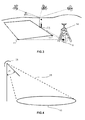
- orientation points (12) are also installed in each of the vertices of the rectangular reference framework (5) and further out of these vertices with respect to the base points (11), such that they are arranged crossways to the base points (11) as shown in Figure 2 , and distant therefrom at a distance of about one meter, with the purpose of having a better orientation of the reference framework (5).
- These points of orientation (12) are not georeferenced, they are only for orientation and should be under radar scanning region.
- each base point (11) must be georeferenced with a GPS unit through the real time kinematik (RTK) method, whose base GPS unit (14) is installed on the reference point (8).
- RTK real time kinematik
- This base GPS unit (14) must be in continuous operation, avoiding any discontinuity of operation while performing the measurement of the base points (11). With this method coordinates of each base point (11) are obtained with an accuracy of ⁇ 2 cm.
- the lighting of the mine field area (201) is performed by using, for this purpose, the radar (4) implemented on the airborne vehicle (3).
- the ground penetration radar (GPR) (4) consists of a discrete step electromagnetic wave generator equally spaced in frequency in the range of 750-3000 MHz.
- the system further comprises an antenna (25) comprising a transmitting antenna for illuminating the area to be scanned and a receiving antenna for receiving the signal reflected from the ground surface and the underground objects.
- Illumination of the covered ground area (16) comprises scanning with the transmitting antenna (25), at a height (277) from 5 to 30 meters, allowing a suitable portion of the ground to be covered.
- Both the radar (4) and the antennae are mounted on a helicopter for being able to safely evolve on the mine field.
- the transmitting and receiving antennae mounted on the outside of the airborne vehicle (3) must aim at an angle (26) ranging from 35° to 55° from the vertical.
- the antenna (25) of the radar (4) scans in discrete frequency steps (minimum 64, maximum 512 steps). Each frequency scanning allows key information for determining the distance to each of detectable objects to be obtained, which are on the covered ground area (16) by the light beam. This frequency scanning must be fast (split second), such that by moving the antennae it is possible to obtain a set of distance measurements for the different objects. The locus of the distances will allow the location of each of the objects composing the scene to be pinpointed.
- both the transmitting and the receiving antenna (25) of the radar (4), mounted outside the airborne vehicle (3), must be moved at a constant speed 27) and at a constant height (277), along a vertical line perpendicular to the vertical and to the light beam axis. With this, a scanning of a strip on the ground (16) is obtained.
- Data obtained from scanning (28) performed by the radar (4) on the area of the mine field (201) is extracted and submitted to the equipment intended for image processing and acquisition.
- the first step consists in generating range sequences.
- Data obtained from the GPR radar receiving antenna and preprocessed by the GPR receiver are processed on a computer using the inverse Fourier transform. This allows obtaining a sequence of measurements of distances (range measurements) to the different objects found in the subsoil.
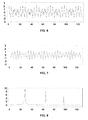
- Figure 6 shows the first set of 128 values obtained from a simulated version of the radar signal (4) for three objects located on the ground area (16) covered by the light beam at distances of 5, 12 and 18 m.
- Figure 7 shows the second set of values obtained from the same simulation for the same three objects located on the ground area (16) covered by the light beam at distances of 5, 12 and 18 m.
- both the transmitting and the receiving antenna (25) move in a straight line forming a scanning, as shown in Figure 5
- the position of objects lying on the ground through can be determined by a series of range measurements as scanning progresses.
- the object(s) located on the ground and within the area covered by the light beam (16) of the radar (4) begin to approach the antennae, until reaching a minimum value, and then move away therefrom until leaving the area covered by the beam (16).
- Successive range measurements made will indicate a displacement in object positions to the left when approaching the antennae, and then a displacement to the right when moving away.
- the second step corresponds to the combination of range measurements.
- the set of range measurements is combined for obtaining an object image.
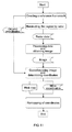
- This operation consists in sequentially aligning each of the range measurements in the same sequence they were obtained in the scanning process in the airborne vehicle (3), as shown in Figure 9 .
- This figure corresponds to the image of a set of 5 objects distributed on an area of 48 x 48 meters, obtained from a computer-simulated scanning.
- the combined set of range measurements is processed by using a detection algorithm allowing the location of each object in the scanning region to be accurately determined, as shown in Figure 9 , where asterisks depict the location of each object. Finally the image is calibrated, that is distances and heights are expressed in meters.
- the processed and calibrated image contains the representation of the objects captured by the radar, which require the application of georeferencing procedures to obtain the object coordinates contained therein comprising geometric encoding, which involves moving from the processed and calibrated image to the scope on the ground and corrections to the angle of incidence of the image, based on measurements of the points created in the reference framework.
- geometric encoding which involves moving from the processed and calibrated image to the scope on the ground and corrections to the angle of incidence of the image, based on measurements of the points created in the reference framework.
- Conversion scope which method consists in positioning values of the image and locating it on the ground to project it based on a coordinate system. It is necessary to know the geometry of the image creation, height of the airborne vehicle (3), time delay between signal from the region closest to the radar with respect to the furthest one, and ground elevation. Resampling, corresponding to a pixel rearrangement, is used to create the even spacing between them (in the scope domain on the ground) across the complete image width.
- Scope conversion on the ground may be performed either during signal processing or during image processing. It is usually applied after radiometric correction. The approach and the algorithms used are dependent on analysis purposes.
- Polynomial transformation uses best fit. Radar image obtained without georeferencing or orthogonal rectification is changed to fit a map projection using various orders.
- GPS ground control points
- the next step in georeferencing is building a point densification based on points obtained on the ground in order to generate a digital field model, with which the image can be orthogonally rectified and all deformations and vertical exaggeration in the image corrected.
- the next step in georeferencing is the correlation between image pixels and imposition of ground point coordinates, controlling the location with the points generated through densification. Based on pixel size as well as image spatial resolution the mean square error is determined. Having the image corrected to points, cubic convolution method is used, which takes the weighted average of sixteen surrounding pixels to estimate the digital value for the final corrected image, this process provides a good record and appearance of the product.
- the risk map can be made. It is generated in a 60 x 60 cm paper format.
- This risk map contains object position vectors in DXF and SHP format (ESRI Shapefile and DXF drawing exchange format of other CAD software.)
- a precision indicator whereby the tolerance determined by the scale for an image obtained with radar data will be the pixel size, this being referred to as spatial resolution of the image.
- these maps should contain centimeter-level precision whereby their scale should not exceed 1:250 (1 mm on the paper equals 25 cm on the ground).
- hybrid maps contain image relating to ground roughness with 20% transparency, plus a grid defined over a maximum distance of one meter.
- AP and AT anti-personnel and anti-tank
- the system concludes and its objective is achieved when marking on the ground the location of the object detected by the radar, that is, remapping, (see Figure 10 ).
- Remapping (23) consists in taking the obtained coordinates of the objects in the image and using a DGPS unit, marking them on the ground.
- RTK real time kinematik
- the base GPS (29) is installed on the reference point (8) in the mine field (201).
- the reference framework (5) that allows for a high level of security for approaching the mine field (201), starts remapping the coordinates of the object detected by the radar (4). This requires scheduling a book, which is part of the mobile GPS unit (30), and which makes it possible to submit the coordinates of the detected objects to be remapped.
- one of the submitted coordinates is selected, and the unit graphically displays the distance thereto and its direction referred to magnetic north.
- the antenna (31) of the mobile GPS (30) is installed on the system created for remapping (23).
- This system created for remapping (23) comprises a tripod where a metal structure containing a 4 m long polycarbonate stick moving in a radial and retractable fashion is to be installed. At one end of this stick the antenna (31) of the mobile GPS (30) is provided having a vertical elbow such that measuring of coordinates visible on the book screen will be actually where the identified mine is.
- a paint mark (32) is used, which is released from a polycarbonate stick end under the antenna (31) of the mobile GPS (30), this being operated from a device fitted on the tripod.
Landscapes
- Engineering & Computer Science (AREA)
- Remote Sensing (AREA)
- Radar, Positioning & Navigation (AREA)
- Physics & Mathematics (AREA)
- General Physics & Mathematics (AREA)
- Electromagnetism (AREA)
- Computer Networks & Wireless Communication (AREA)
- Life Sciences & Earth Sciences (AREA)
- Environmental & Geological Engineering (AREA)
- Geology (AREA)
- General Life Sciences & Earth Sciences (AREA)
- Geophysics (AREA)
- Radar Systems Or Details Thereof (AREA)
- Position Fixing By Use Of Radio Waves (AREA)
- Geophysics And Detection Of Objects (AREA)
Applications Claiming Priority (2)
| Application Number | Priority Date | Filing Date | Title |
|---|---|---|---|
| CL2008000024A CL2008000024A1 (es) | 2008-01-04 | 2008-01-04 | Sistema y metodo para la deteccion, localizacion e identificacion de objetos en suelo y subsuelo que se encuentran en un area de interes previamente referenciada. |
| PCT/ES2009/070001 WO2009087260A1 (es) | 2008-01-04 | 2009-01-02 | Sistema y método para la detección, localización e identificación de objetos en suelo y subsuelo que se encuentran en un área de interés previamente referenciada |
Publications (2)
| Publication Number | Publication Date |
|---|---|
| EP2244101A1 true EP2244101A1 (de) | 2010-10-27 |
| EP2244101A4 EP2244101A4 (de) | 2015-10-14 |
Family
ID=40852815
Family Applications (1)
| Application Number | Title | Priority Date | Filing Date |
|---|---|---|---|
| EP09700523.5A Withdrawn EP2244101A4 (de) | 2008-01-04 | 2009-01-02 | System und verfahren zur erkennung, ortung und identifizierung von objekten über dem boden und unter dem boden in einem vorreferenzierten interessensbereich |
Country Status (5)
| Country | Link |
|---|---|
| US (1) | US8508402B2 (de) |
| EP (1) | EP2244101A4 (de) |
| CL (1) | CL2008000024A1 (de) |
| IL (1) | IL206750A (de) |
| WO (1) | WO2009087260A1 (de) |
Cited By (7)
| Publication number | Priority date | Publication date | Assignee | Title |
|---|---|---|---|---|
| CN102636501A (zh) * | 2012-03-26 | 2012-08-15 | 中南大学 | 一种剔除表层钢筋对高频电磁波影响的滤波方法 |
| RU2515191C2 (ru) * | 2012-06-19 | 2014-05-10 | Вячеслав Адамович Заренков | Способ обнаружения местонахождения засыпанных биообъектов или их останков и устройство для его осуществления |
| ES2511941A1 (es) * | 2014-03-06 | 2014-10-23 | Xpresa Geophysics S.L. | Sistema y método de localización y cartografía de activos enterrados |
| CN103499612B (zh) * | 2013-10-14 | 2015-12-09 | 浙江水利水电学院 | 一种用于海堤工程隐患探测的组合物探方法 |
| CN112934758A (zh) * | 2020-12-14 | 2021-06-11 | 中科院计算所西部高等技术研究院 | 基于图像识别的煤炭分拣拨手控制方法 |
| CN113607186A (zh) * | 2021-07-26 | 2021-11-05 | 成都飞机工业(集团)有限责任公司 | 一种消除机载瞄准吊舱安装误差的校准方法 |
| CN118837969A (zh) * | 2023-04-24 | 2024-10-25 | 中国石油天然气股份有限公司 | 一种庭院燃气非金属管道位置走向的探测方法 |
Families Citing this family (30)
| Publication number | Priority date | Publication date | Assignee | Title |
|---|---|---|---|---|
| US8694258B2 (en) * | 2010-02-14 | 2014-04-08 | Vermeer Manufacturing Company | Derivative imaging for subsurface object detection |
| US8730332B2 (en) | 2010-09-29 | 2014-05-20 | Digitaloptics Corporation | Systems and methods for ergonomic measurement |
| US8587666B2 (en) * | 2011-02-15 | 2013-11-19 | DigitalOptics Corporation Europe Limited | Object detection from image profiles within sequences of acquired digital images |
| US8587665B2 (en) * | 2011-02-15 | 2013-11-19 | DigitalOptics Corporation Europe Limited | Fast rotation estimation of objects in sequences of acquired digital images |
| US8705894B2 (en) | 2011-02-15 | 2014-04-22 | Digital Optics Corporation Europe Limited | Image rotation from local motion estimates |
| US10043263B1 (en) * | 2011-07-05 | 2018-08-07 | Bernard Fryshman | Mobile system for explosive device detection and instant active response |
| US8774985B2 (en) * | 2011-07-22 | 2014-07-08 | The Boeing Company | Systems and methods for generating a command trajectory |
| US8786485B2 (en) * | 2011-08-30 | 2014-07-22 | Masachusetts Institute Of Technology | Mobile coherent change detection ground penetrating radar |
| US8842937B2 (en) * | 2011-11-22 | 2014-09-23 | Raytheon Company | Spectral image dimensionality reduction system and method |
| US8655091B2 (en) | 2012-02-24 | 2014-02-18 | Raytheon Company | Basis vector spectral image compression |
| US9870504B1 (en) * | 2012-07-12 | 2018-01-16 | The United States Of America, As Represented By The Secretary Of The Army | Stitched image |
| GB201216818D0 (en) * | 2012-09-20 | 2012-11-07 | Bae Systems Plc | Detection of a target in a scene |
| GB2506687B (en) | 2012-10-08 | 2018-02-07 | Bae Systems Plc | Hyperspectral imaging of a moving scene |
| US12182937B2 (en) | 2013-07-23 | 2024-12-31 | Hover Inc. | 3D building model materials auto-populator |
| US11721066B2 (en) | 2013-07-23 | 2023-08-08 | Hover Inc. | 3D building model materials auto-populator |
| WO2015061735A1 (en) | 2013-10-25 | 2015-04-30 | Hover Inc. | Estimating dimensions of geo-referenced ground-level imagery using orthogonal imagery |
| CN105911559A (zh) * | 2016-06-02 | 2016-08-31 | 中国科学院光电研究院 | 基于可见光-近红外-短波红外波段的激光雷达系统 |
| KR101967305B1 (ko) * | 2016-10-14 | 2019-05-15 | 주식회사 만도 | 차량의 보행자 인식 방법 및 차량의 보행자 인식 시스템 |
| ES2984945T3 (es) * | 2017-01-27 | 2024-10-31 | Massachusetts Inst Technology | Método y sistema para la localización de un vehículo utilizando un radar de penetración superficial |
| CN107918160B (zh) * | 2017-11-10 | 2023-12-19 | 中国石油化工股份有限公司 | 一种废弃井全面扫查系统及方法 |
| CN107976673B (zh) * | 2017-11-17 | 2020-02-07 | 中国科学技术大学 | 提高大场景目标成像质量的mimo雷达成像方法 |
| IT201800009761A1 (it) * | 2018-10-24 | 2020-04-24 | Ids Georadar Srl | Sistema fotogrammetrico di ausilio al posizionamento dei dati georadar sullo scenario di misura |
| CN109782274B (zh) * | 2019-01-31 | 2023-05-16 | 长安大学 | 一种基于探地雷达信号时频统计特征的水损害识别方法 |
| US10895637B1 (en) * | 2019-07-17 | 2021-01-19 | BGA Technology LLC | Systems and methods for mapping manmade objects buried in subterranean surfaces using an unmanned aerial vehicle integrated with radar sensor equipment |
| CN110554437A (zh) * | 2019-10-02 | 2019-12-10 | 湖南科技大学 | 雷场多源信息同步探测系统 |
| US12183067B2 (en) * | 2020-05-07 | 2024-12-31 | Hypergiant Industries, Inc. | Volumetric baseline image generation and object identification |
| CN113050175B (zh) * | 2021-03-08 | 2022-05-13 | 吉林大学 | 直升机航空电磁收录装置及发射源参数识别方法 |
| CN113327229B (zh) * | 2021-05-27 | 2023-09-22 | 扬州大学 | 一种快速定位像点网格的方法 |
| CN113359197B (zh) * | 2021-06-03 | 2024-01-23 | 河北省地震局 | 一种适于浅层高精度的曲地表叠加成像方法 |
| US12060148B2 (en) | 2022-08-16 | 2024-08-13 | Honeywell International Inc. | Ground resonance detection and warning system and method |
Family Cites Families (13)
| Publication number | Priority date | Publication date | Assignee | Title |
|---|---|---|---|---|
| GB666335A (en) * | 1949-03-28 | 1952-02-13 | Suchy Holdings Ltd | Improvements in and relating to radar reflectors |
| US5499029A (en) * | 1992-07-14 | 1996-03-12 | Eg&G Energy Measurements, Inc. | Wide band stepped frequency ground penetrating radar |
| US5502444A (en) * | 1994-09-23 | 1996-03-26 | Mandex, Inc. | Method and apparatus for improving the signal-to-clutter ratio of an airborne earth penetrating radar |
| US6140959A (en) * | 1996-03-13 | 2000-10-31 | Caterpillar Inc. | Self-calibrating GPS reference station and method |
| US5673050A (en) * | 1996-06-14 | 1997-09-30 | Moussally; George | Three-dimensional underground imaging radar system |
| US6178253B1 (en) * | 1997-10-10 | 2001-01-23 | Case Corporation | Method of determining and treating the health of a crop |
| MXPA02009278A (es) * | 2000-03-22 | 2004-09-06 | Hot Shot Radar Inspections Llc | Metodo y sistema para la identificacion de objetos subterraneos. |
| US6982666B2 (en) * | 2001-06-08 | 2006-01-03 | The United States Of America As Represented By The Secretary Of The Navy | Three-dimensional synthetic aperture radar for mine detection and other uses |
| CA2811172A1 (en) * | 2004-07-20 | 2006-02-09 | Global Precision Solutions, Llp | Precision gps driven utility asset management and utility damage prevention system and method |
| US7382312B2 (en) * | 2004-10-12 | 2008-06-03 | George Mason Intellectual Properties, Inc. | Syntactic target classifier |
| WO2007058670A2 (en) * | 2005-03-31 | 2007-05-24 | Southwest Research Institute | Signal processing methods for ground penetrating radar from elevated platforms |
| EP1965223B1 (de) * | 2007-03-02 | 2013-12-18 | Saab Ab | Bilderzeugender Unteroberflächenradar |
| US8115666B2 (en) * | 2008-04-17 | 2012-02-14 | Mirage Systems, Inc. | Ground penetrating synthetic aperture radar |
-
2008
- 2008-01-04 CL CL2008000024A patent/CL2008000024A1/es unknown
-
2009
- 2009-01-02 WO PCT/ES2009/070001 patent/WO2009087260A1/es not_active Ceased
- 2009-01-02 US US12/735,344 patent/US8508402B2/en not_active Expired - Fee Related
- 2009-01-02 EP EP09700523.5A patent/EP2244101A4/de not_active Withdrawn
-
2010
- 2010-07-01 IL IL206750A patent/IL206750A/en not_active IP Right Cessation
Non-Patent Citations (1)
| Title |
|---|
| See references of WO2009087260A1 * |
Cited By (9)
| Publication number | Priority date | Publication date | Assignee | Title |
|---|---|---|---|---|
| CN102636501A (zh) * | 2012-03-26 | 2012-08-15 | 中南大学 | 一种剔除表层钢筋对高频电磁波影响的滤波方法 |
| CN102636501B (zh) * | 2012-03-26 | 2014-09-03 | 中南大学 | 一种剔除表层钢筋对高频电磁波影响的滤波方法 |
| RU2515191C2 (ru) * | 2012-06-19 | 2014-05-10 | Вячеслав Адамович Заренков | Способ обнаружения местонахождения засыпанных биообъектов или их останков и устройство для его осуществления |
| CN103499612B (zh) * | 2013-10-14 | 2015-12-09 | 浙江水利水电学院 | 一种用于海堤工程隐患探测的组合物探方法 |
| ES2511941A1 (es) * | 2014-03-06 | 2014-10-23 | Xpresa Geophysics S.L. | Sistema y método de localización y cartografía de activos enterrados |
| CN112934758A (zh) * | 2020-12-14 | 2021-06-11 | 中科院计算所西部高等技术研究院 | 基于图像识别的煤炭分拣拨手控制方法 |
| CN113607186A (zh) * | 2021-07-26 | 2021-11-05 | 成都飞机工业(集团)有限责任公司 | 一种消除机载瞄准吊舱安装误差的校准方法 |
| CN113607186B (zh) * | 2021-07-26 | 2023-11-10 | 成都飞机工业(集团)有限责任公司 | 一种消除机载瞄准吊舱安装误差的校准方法 |
| CN118837969A (zh) * | 2023-04-24 | 2024-10-25 | 中国石油天然气股份有限公司 | 一种庭院燃气非金属管道位置走向的探测方法 |
Also Published As
| Publication number | Publication date |
|---|---|
| CL2008000024A1 (es) | 2009-01-16 |
| IL206750A0 (en) | 2010-12-30 |
| IL206750A (en) | 2017-01-31 |
| EP2244101A4 (de) | 2015-10-14 |
| WO2009087260A1 (es) | 2009-07-16 |
| US20110037639A1 (en) | 2011-02-17 |
| US8508402B2 (en) | 2013-08-13 |
Similar Documents
| Publication | Publication Date | Title |
|---|---|---|
| US8508402B2 (en) | System and method for detecting, locating and identifying objects located above the ground and below the ground in a pre-referenced area of interest | |
| Fernández et al. | Synthetic aperture radar imaging system for landmine detection using a ground penetrating radar on board a unmanned aerial vehicle | |
| US10788584B2 (en) | Apparatus and method for determining defects in dielectric materials and detecting subsurface objects | |
| US4381544A (en) | Process and apparatus for geotechnic exploration | |
| Ferrero et al. | Advanced geostructural survey methods applied to rock mass characterization | |
| Nagihara et al. | Use of a three‐dimensional laser scanner to digitally capture the topography of sand dunes in high spatial resolution | |
| Merkle et al. | Fusion of ground penetrating radar and laser scanning for infrastructure mapping | |
| Michoud et al. | Landslide detection and monitoring capability of boat-based mobile laser scanning along Dieppe coastal cliffs, Normandy | |
| RU2591875C1 (ru) | Способ построения карты экзогенных геологических процессов местности вдоль трассы магистрального нефтепровода | |
| WO2002008689A1 (en) | Method and apparatus for mapping three-dimensional features | |
| RU2444760C1 (ru) | Способ съемки нижней поверхности ледяного покрова | |
| Vanneschi et al. | Geological 3D modeling for excavation activity in an underground marble quarry in the Apuan Alps (Italy) | |
| KR20220083195A (ko) | 지하시설물에 대한 3차원 현장 정보 취득이 가능한 지하시설물 현장 탐사장치 및 이를 이용한 지하시설물 현장 탐사방법 | |
| Góes et al. | Refraction effect in SAR processing for focused subsurface tomography | |
| CN117437559A (zh) | 基于无人机的煤炭矿区地表岩移变形检测方法、装置 | |
| González-Jorge et al. | Comparison between laser scanning, single-image rectification and ground-penetrating radar technologies in forensic science | |
| WO2017222481A1 (en) | Gyroscopic georadar | |
| Maerz et al. | Measuring orientations of individual concealed sub-vertical discontinuities in sandstone rock cuts integrating ground penetrating radar and terrestrial LIDAR | |
| EP4505414A1 (de) | Verfahren zur erzeugung von 3d-karten verborgener objekte unter verwendung von daten zur erkennung nicht-rangiger funktionen | |
| Donovan et al. | The application of three-dimensional imaging to rock discontinuity characterization | |
| Javed | Rock mass characterization of the Underground Research Laboratory of Aalto University (URLA) | |
| Aqeel | Measuring the orientations of hidden subvertical joints in highways rock cuts using ground penetrating radar in combination with LIDAR | |
| Singh et al. | Synthetic aperture radar communication | |
| Foessel-Bunting et al. | Radar sensor for an autonomous Antarctic explorer | |
| Bals et al. | Monitoring Methods and Instruments |
Legal Events
| Date | Code | Title | Description |
|---|---|---|---|
| PUAI | Public reference made under article 153(3) epc to a published international application that has entered the european phase |
Free format text: ORIGINAL CODE: 0009012 |
|
| 17P | Request for examination filed |
Effective date: 20100804 |
|
| AK | Designated contracting states |
Kind code of ref document: A1 Designated state(s): AT BE BG CH CY CZ DE DK EE ES FI FR GB GR HR HU IE IS IT LI LT LU LV MC MK MT NL NO PL PT RO SE SI SK TR |
|
| AX | Request for extension of the european patent |
Extension state: AL BA RS |
|
| RIN1 | Information on inventor provided before grant (corrected) |
Inventor name: GUARINI HERRMANN, MARCELO WALTER Inventor name: DURAN TORO, MARIO MANUEL |
|
| DAX | Request for extension of the european patent (deleted) | ||
| RA4 | Supplementary search report drawn up and despatched (corrected) |
Effective date: 20150914 |
|
| RIC1 | Information provided on ipc code assigned before grant |
Ipc: G01S 7/41 20060101ALI20150908BHEP Ipc: G01C 15/00 20060101ALN20150908BHEP Ipc: G01V 3/17 20060101ALI20150908BHEP Ipc: G01S 13/89 20060101ALN20150908BHEP Ipc: G01S 13/02 20060101AFI20150908BHEP Ipc: G01S 13/88 20060101ALI20150908BHEP Ipc: G01S 13/86 20060101ALI20150908BHEP Ipc: G01S 19/43 20100101ALI20150908BHEP |
|
| STAA | Information on the status of an ep patent application or granted ep patent |
Free format text: STATUS: THE APPLICATION IS DEEMED TO BE WITHDRAWN |
|
| 18D | Application deemed to be withdrawn |
Effective date: 20160412 |