EP2243949A1 - Fuel Injector - Google Patents
Fuel Injector Download PDFInfo
- Publication number
- EP2243949A1 EP2243949A1 EP10154608A EP10154608A EP2243949A1 EP 2243949 A1 EP2243949 A1 EP 2243949A1 EP 10154608 A EP10154608 A EP 10154608A EP 10154608 A EP10154608 A EP 10154608A EP 2243949 A1 EP2243949 A1 EP 2243949A1
- Authority
- EP
- European Patent Office
- Prior art keywords
- nozzle needle
- fuel injector
- chamber
- coupling rod
- pressure chamber
- Prior art date
- Legal status (The legal status is an assumption and is not a legal conclusion. Google has not performed a legal analysis and makes no representation as to the accuracy of the status listed.)
- Granted
Links
- 239000000446 fuel Substances 0.000 title claims description 34
- 230000008878 coupling Effects 0.000 claims abstract description 48
- 238000010168 coupling process Methods 0.000 claims abstract description 48
- 238000005859 coupling reaction Methods 0.000 claims abstract description 48
- 238000002347 injection Methods 0.000 claims abstract description 9
- 239000007924 injection Substances 0.000 claims abstract description 9
- 238000002485 combustion reaction Methods 0.000 claims abstract description 4
- 238000007789 sealing Methods 0.000 claims description 4
- 239000000725 suspension Substances 0.000 claims 1
- 230000006835 compression Effects 0.000 description 3
- 238000007906 compression Methods 0.000 description 3
- 239000012530 fluid Substances 0.000 description 3
- 238000006073 displacement reaction Methods 0.000 description 2
- 230000007423 decrease Effects 0.000 description 1
- 239000002828 fuel tank Substances 0.000 description 1
- 230000000284 resting effect Effects 0.000 description 1
- 238000004904 shortening Methods 0.000 description 1
Images

Classifications
-
- F—MECHANICAL ENGINEERING; LIGHTING; HEATING; WEAPONS; BLASTING
- F02—COMBUSTION ENGINES; HOT-GAS OR COMBUSTION-PRODUCT ENGINE PLANTS
- F02M—SUPPLYING COMBUSTION ENGINES IN GENERAL WITH COMBUSTIBLE MIXTURES OR CONSTITUENTS THEREOF
- F02M51/00—Fuel-injection apparatus characterised by being operated electrically
- F02M51/06—Injectors peculiar thereto with means directly operating the valve needle
- F02M51/0603—Injectors peculiar thereto with means directly operating the valve needle using piezoelectric or magnetostrictive operating means
-
- B—PERFORMING OPERATIONS; TRANSPORTING
- B06—GENERATING OR TRANSMITTING MECHANICAL VIBRATIONS IN GENERAL
- B06B—METHODS OR APPARATUS FOR GENERATING OR TRANSMITTING MECHANICAL VIBRATIONS OF INFRASONIC, SONIC, OR ULTRASONIC FREQUENCY, e.g. FOR PERFORMING MECHANICAL WORK IN GENERAL
- B06B1/00—Methods or apparatus for generating mechanical vibrations of infrasonic, sonic, or ultrasonic frequency
- B06B1/02—Methods or apparatus for generating mechanical vibrations of infrasonic, sonic, or ultrasonic frequency making use of electrical energy
- B06B1/06—Methods or apparatus for generating mechanical vibrations of infrasonic, sonic, or ultrasonic frequency making use of electrical energy operating with piezoelectric effect or with electrostriction
- B06B1/0644—Methods or apparatus for generating mechanical vibrations of infrasonic, sonic, or ultrasonic frequency making use of electrical energy operating with piezoelectric effect or with electrostriction using a single piezoelectric element
- B06B1/0655—Methods or apparatus for generating mechanical vibrations of infrasonic, sonic, or ultrasonic frequency making use of electrical energy operating with piezoelectric effect or with electrostriction using a single piezoelectric element of cylindrical shape
-
- F—MECHANICAL ENGINEERING; LIGHTING; HEATING; WEAPONS; BLASTING
- F02—COMBUSTION ENGINES; HOT-GAS OR COMBUSTION-PRODUCT ENGINE PLANTS
- F02M—SUPPLYING COMBUSTION ENGINES IN GENERAL WITH COMBUSTIBLE MIXTURES OR CONSTITUENTS THEREOF
- F02M2200/00—Details of fuel-injection apparatus, not otherwise provided for
- F02M2200/70—Linkage between actuator and actuated element, e.g. between piezoelectric actuator and needle valve or pump plunger
- F02M2200/701—Linkage between actuator and actuated element, e.g. between piezoelectric actuator and needle valve or pump plunger mechanical
-
- F—MECHANICAL ENGINEERING; LIGHTING; HEATING; WEAPONS; BLASTING
- F02—COMBUSTION ENGINES; HOT-GAS OR COMBUSTION-PRODUCT ENGINE PLANTS
- F02M—SUPPLYING COMBUSTION ENGINES IN GENERAL WITH COMBUSTIBLE MIXTURES OR CONSTITUENTS THEREOF
- F02M2200/00—Details of fuel-injection apparatus, not otherwise provided for
- F02M2200/70—Linkage between actuator and actuated element, e.g. between piezoelectric actuator and needle valve or pump plunger
- F02M2200/703—Linkage between actuator and actuated element, e.g. between piezoelectric actuator and needle valve or pump plunger hydraulic
- F02M2200/704—Linkage between actuator and actuated element, e.g. between piezoelectric actuator and needle valve or pump plunger hydraulic with actuator and actuated element moving in different directions, e.g. in opposite directions
Definitions
- the invention relates to a fuel injector arranged in an injector body and connectable to a high pressure fuel source high pressure space, which is connected via a nozzle needle or the like controlled fuel injection injectors with a combustion chamber, and arranged in the injector with a low-pressure chamber, which is connected to a relative pressure-free low-pressure side return line of a low-pressure system can be connected, and with an actuator which actuates the nozzle needle via a driving rod coupled to the actuator coupling rod.
- Fuel injectors that control the injection of fuel from a high-pressure system, usually a so-called common rail, in a combustion chamber of an engine or the like are used as standard on motor vehicles. This provides the advantage that the high pressure can in principle be readily adapted to different operating conditions and on the other hand, the injection phases are freely controllable.
- Currently in motor vehicles mainly fuel injectors are used with servo-controlled nozzle needles.
- the actuator controls via corresponding valve elements present in a servo space pressure, which in turn controls the nozzle needle.
- the basic advantage of a fuel injector with servo-controlled nozzle needle is that only small demands are placed on the performance of the actuator.
- nozzle needle In fuel injectors with directly controlled nozzle needles comparable delay times are not considered because a direct drive coupling between the actuator and the nozzle needle is present.
- the limited performance of the actuators must be considered, i. H. It must be ensured that the strokes of the nozzle needle counteract only comparatively low resulting fluidic forces.
- the nozzle needle should be "pressure balanced" arranged such that the forces acting in the opening and / or closing direction of the nozzle needle fluidic forces compensate each other as much as possible.
- a pressure-balanced arrangement of the nozzle needle is not readily achievable, because there are no stationary pressure conditions in the fuel injector. Rather, significantly different pressures in the closing or opening direction become effective when the nozzle needle is open or closed.
- the invention is based on the general idea of constantly exploiting the pressure generated by the high-pressure fuel source to produce a force which supports the closing thrust of the nozzle needle.
- the coupling rod with a plunger-like end remote from the nozzle can be arranged displaceably in a connectable with the high pressure source terminal compartment which is constantly connected to the high pressure source and can communicate with the high pressure chamber via a high pressure line passing through the injector body.
- connection space can be formed as a connection bore provided in the injector body, which is provided for connection of the injector to the high-pressure system or the common rail.
- the coupling rod may be mechanically coupled or integrally connected to the nozzle needle.
- the in Fig. 1 shown fuel injector has a built injector 1, which includes a low-pressure chamber 2 and a high-pressure chamber 3.
- the low-pressure chamber 2 can be connected via a return line 4 with a low-pressure system, which in turn communicates via a throttle with a relatively pressureless fuel tank.
- the high pressure chamber 3 is connected via a high pressure line 5 with a high pressure fuel source, usually a so-called common rail 6, connectable.
- the high-pressure chamber 3 can be connected via the interior of a nozzle body 7 with injection nozzles 9 controlled by a nozzle needle 8.
- the nozzle-side end of the nozzle needle 8 sits on a the injectors 9 annularly comprehensive fit within the nozzle body 7, so that a nozzle inlet chamber 10 is separated from the rest of the interior of the nozzle body 7.
- the nozzle needle 8 is axially displaceably guided within the nozzle body, for example by means of axial webs on the outer circumference of the nozzle needle 8. These webs may be arranged star-shaped in axial view of the nozzle needle 8, such that remain free between the axial webs axial passages for the passage of fluid.
- a closing throttle 11 is provided within the nozzle body 7, which is formed in the illustrated example as an annular gap between the inner wall of the nozzle body 7 and the outer periphery of a arranged on the nozzle needle 8 flange. The purpose of this closing throttle 11 will be explained below.
- the nozzle-distal end of the nozzle needle 8 is slidably and tightly guided in a corresponding bore of an intermediate body 12, such that a subsequent, housed in an intermediate body 13 chamber 14 is shut off from the high-pressure chamber 3.
- the chamber 14 is connected via an intermediate body 13 passing through the radial bore 15 with an intermediate body 12 and 13 enclosing annulus, which in turn communicates with the low-pressure chamber 2. Accordingly is in the chamber 14 always before the low pressure, and an optionally occurring on the outer circumference of the nozzle needle 8 leakage current from the high-pressure chamber 3 to the chamber 14 is discharged via the return line 4.
- nozzle-distal end of the nozzle needle 8 connects to a coupling rod 16, which is guided on the one hand in a coaxial to the nozzle needle 8 bore in the intermediate body 13 and on the other hand in an axial central bore 17 in the upper portion of the injector body 1.
- the central bore 17 forms a connection bore for connecting the fuel injector to the high-pressure system or the common rail 6, which communicates via the central bore 17 with the high-pressure line 5.
- a coupling rod 16 concentric piezoelectric actuator 19 is arranged, which is supported with a front-side upper annular disc at an upper bottom of the low-pressure chamber 2 and held in this position by a helical compression spring 20, the upper end is clamped against the said annular disc and the lower end against the facing end side of a coupler piston 21 arranged on the coupling rod 16. Accordingly, the coupling rod 16 is tensioned by the spring 20 downwards against the nozzle needle 8.
- a further annular end plate with an annular, concentric with the coupler piston 21 annular piston 22 is arranged on the underside of the actuator 19, a further annular end plate with an annular, concentric with the coupler piston 21 annular piston 22 is arranged.
- This is on the one hand tight and displaceable on the coupler piston 21 and the other tight and slidably guided in a cylinder 23 which is arranged on the upper end side of the intermediate body 13 and separated together with the annular piston 22 and the coupler piston 21 a coupler space 24 from the low pressure chamber 2.
- the nozzle-side seat of the nozzle needle 8 and the upper end of the coupling rod 16 can be achieved that the necessary for the downward stroke of the annular piston 22 power of the actuator 19 remains low and, accordingly, a low-power actuator 19 is sufficient To bring the nozzle needle 8 from the closed position shown in the open position.
- the nozzle needle 8 As soon as the nozzle needle 8 has been raised to its open position, the same pressure is present in the nozzle inlet space 10 as in the remaining interior of the inner body 7, ie. H. the nozzle needle 8 is acted upon on its entire cross-section of the pressure in the interior of the nozzle body 7 in the opening direction.
- the open position of the nozzle needle 8 d. H. in the injection phase of the fuel injector, however, due to the flow from the high pressure chamber 3 to the injectors 9 at the closing throttle 11 a pressure difference decreases, such that the pressure in the interior of the nozzle body 7, the pressure in the high pressure chamber 3 is more or less significantly below.
- a tube spring 25, which is biased to train is provided.
- the actuator 19 is securely brought into its axially short state after electrical discharge.
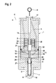
- the embodiment of the Fig. 2 differs from the embodiment described above the Fig. 1 essentially by the fact that the in Fig. 1 provided closing throttle 11 is eliminated and the nozzle needle 8 is hydraulically coupled to the coupling rod 16.
- a sealing sleeve 26 is slidably guided on the upper end of the nozzle needle 8, which is clamped by a supported on a flange on the nozzle needle 8 helical compression spring 27 with a sharp annular edge against the facing end face of the intermediate body 12, wherein the sealing sleeve 26 sealingly seated on the intermediate body 12 at an annular contact zone.
- the sealing sleeve 26 divides from the high-pressure chamber 3 from a slave chamber 28, which is connected via a bore 29, which may optionally be designed as a throttle, with a transmitter chamber 30 within the intermediate body 12.
- a transmitter chamber 30 within the intermediate body 12.
- the lower end of the coupling rod 16 is arranged as a positive displacement plunger, while the formed at the mouth of the bore 29 in the encoder chamber 30 ring stage can serve as an end stop for the illustrated lower position of the coupling rod 16.
- the coupler chamber 24 is separated from the low-pressure chamber 2 directly by the coupler piston 21 and the annular piston 22, which in turn is guided on the inner circumference of the low-pressure chamber 2 dense and displaceable.
- Fig. 2 the electrically discharged state of the actuator 19 is shown. Accordingly, the annular piston 22 assumes an upper position. Now, if the actuator 19 is electrically charged, it is axially elongated, so that the annular piston 22 is pushed downward. This results in that the coupler piston 21 is displaced upward with the coupling rod 16, whereby the volume of the transmitter chamber 30 increases and fluid flows from the receiver chamber 28 into the transmitter chamber 30. Thus, the nozzle needle 8 is lifted out of the illustrated closed position.
- Fig. 2 In the embodiment of the Fig. 2 is the leadership of the sleeve 26 on the nozzle needle 8 is formed so that a strong throttled connection between the Nehmerraum 28 and the high-pressure chamber 3 is present.
- a similar high pressure as in the high-pressure room 3 thus arises in the case of an electrically non-brindle actuator 19 (resting state of the injector).
- the coupling rod 16 In order to is the coupling rod 16 arranged pressure balanced, because the pressure forces in the encoder chamber 30 counteract the pressure forces in the central bore 17 and the displacement effective cross sections of the upper and lower end of the coupling rod 16 are the same size.
- the coupling rod 16 can be adjusted with low actuating force, and the nozzle needle 8 follows the stroke adjustment of the coupling rod 16, wherein according to the different cross sections of the coupling rod 16 in the encoder chamber 30 and the nozzle needle 8 in the slave chamber 28 is a Hubüber acid, ie in the example shown is the A possibly occurring at the outer periphery of the lower end of the coupling rod 16 leakage current is taken up by the interspersed by the coupling rod 16 chamber 14 and passed through the radial bore 15 in the space connected to the low-pressure chamber 2 space 31 , so that the leakage current is ultimately passed through the low-pressure chamber 2 in the return line 4 and kept away from the coupler chamber 24.
- a particular advantage of the embodiment of Fig. 2 is that on the way from the high pressure source 6 to the injectors 9 virtually no pressure drop occurring through throttle losses occurs, so that the performance of the high pressure source at the injectors 9 is still effective.
Abstract
Description
Die Erfindung bezieht sich auf einen Kraftstoffinjektor mit in einem Injektorkörper angeordnetem und mit einer Hochdruckquelle für Kraftstoff verbindbarem Hochdruckraum, der über von einer Düsennadel oder dergleichen gesteuerte Einspritzdüsen zur Kraftstoffeinspritzung mit einem Brennraum verbindbar ist, und mit einem im Injektorgehäuse angeordnetem Niederdruckraum, der an eine relativ drucklose niederdruckseitige Rücklaufleitung eines Niederdrucksystems anschließbar ist, und mit einem Aktor, welcher die Düsennadel über eine mit dem Aktor antriebsmäßig gekoppelte Koppelstange betätigt.The invention relates to a fuel injector arranged in an injector body and connectable to a high pressure fuel source high pressure space, which is connected via a nozzle needle or the like controlled fuel injection injectors with a combustion chamber, and arranged in the injector with a low-pressure chamber, which is connected to a relative pressure-free low-pressure side return line of a low-pressure system can be connected, and with an actuator which actuates the nozzle needle via a driving rod coupled to the actuator coupling rod.
Kraftstoffinjektoren, die die Einspritzung von Kraftstoff aus einem Hochdrucksystem, i. d. R. ein so genanntes Common Rail, in einem Brennraum eines Motors oder dergleichen steuern, werden serienmäßig bei Kraftfahrzeugen eingesetzt. Damit wird der Vorteil geboten, dass der Hochdruck prinzipiell ohne weiteres an unterschiedliche Betriebszustände angepasst werden kann und andererseits die Einspritzphasen frei steuerbar sind. Derzeit werden in Kraftfahrzeugen überwiegend Kraftstoffinjektoren mit servogesteuerten Düsennadeln eingesetzt. Hier steuert der Aktor über entsprechende Ventilelemente den in einem Servoraum vorliegenden Druck, der dann seinerseits die Düsennadel steuert. Der grundsätzliche Vorteil eines Kraftstoffinjektors mit servogesteuerter Düsennadel liegt darin, dass an die Leistungsfähigkeit des Aktors nur geringe Anforderungen gestellt werden. Andererseits muss beim Betrieb eines servogesteuerten Kraftstoffinjektors berücksichtigt werden, dass zwischen den Hüben des Aktors einerseits und den Hüben der Düsennadel andererseits Verzögerungszeiten auftreten können.Fuel injectors that control the injection of fuel from a high-pressure system, usually a so-called common rail, in a combustion chamber of an engine or the like are used as standard on motor vehicles. This provides the advantage that the high pressure can in principle be readily adapted to different operating conditions and on the other hand, the injection phases are freely controllable. Currently in motor vehicles mainly fuel injectors are used with servo-controlled nozzle needles. Here, the actuator controls via corresponding valve elements present in a servo space pressure, which in turn controls the nozzle needle. The basic advantage of a fuel injector with servo-controlled nozzle needle is that only small demands are placed on the performance of the actuator. On the other hand, when operating a servo-controlled fuel injector, it must be taken into account that delay times can occur between the strokes of the actuator on the one hand and the strokes of the nozzle needle on the other hand.
Bei Kraftstoffinjektoren mit direkt gesteuerten Düsennadeln sind vergleichbare Verzögerungszeiten nicht zu berücksichtigen, weil eine direkte Antriebskopplung zwischen Aktor und Düsennadel vorhanden ist. Jedoch muss bei der Konstruktion direkt gesteuerter Kraftstoffinjektoren die begrenzte Leistungsfähigkeit der Aktoren berücksichtigt werden, d. h. es muss gewährleistet werden, dass den Hüben der Düsennadel nur vergleichsweise geringe resultierende fluidische Kräfte entgegen wirken. Im Idealfall sollte die Düsennadel "druckausgeglichen" angeordnet sein, derart, dass die in Öffnungs- und/oder Schließrichtung der Düsennadel wirkenden fluidischen Kräfte einander weitestgehend kompensieren. Eine druckausgeglichene Anordnung der Düsennadel ist aber nicht ohne weiteres erreichbar, weil im Kraftstoffinjektor keine stationären Druckverhältnisse vorliegen. Vielmehr werden bei geöffneter bzw. geschlossener Düsennadel deutlich unterschiedliche Drücke in Schließ- oder Öffnungsrichtung wirksam.In fuel injectors with directly controlled nozzle needles comparable delay times are not considered because a direct drive coupling between the actuator and the nozzle needle is present. However, when designing directly controlled fuel injectors, the limited performance of the actuators must be considered, i. H. It must be ensured that the strokes of the nozzle needle counteract only comparatively low resulting fluidic forces. Ideally, the nozzle needle should be "pressure balanced" arranged such that the forces acting in the opening and / or closing direction of the nozzle needle fluidic forces compensate each other as much as possible. However, a pressure-balanced arrangement of the nozzle needle is not readily achievable, because there are no stationary pressure conditions in the fuel injector. Rather, significantly different pressures in the closing or opening direction become effective when the nozzle needle is open or closed.
Deshalb ist es Aufgabe der Erfindung, einen Kraftstoffinjektor zu schaffen, bei dem zusätzliche Konstruktionsparameter zur Gewährleistung eines Druckausgleiches an der Düsennadel geboten werden.Therefore, it is an object of the invention to provide a fuel injector, are offered in the additional design parameters to ensure a pressure equalization on the nozzle needle.
Diese Aufgabe wird bei einem Kraftstoffinjektor der eingangs angegebenen Art erfindungsgemäß dadurch gelöst, dass die Koppelstange auf einem vorgehbaren Querschnitt vom Hochdruck in Richtung der Schließlage der Düsennadel beaufschlagbar ist.This object is achieved in a fuel injector of the type specified according to the invention that the coupling rod can be acted upon on a vorgehbaren cross-section of the high pressure in the direction of the closed position of the nozzle needle.
Die Erfindung beruht auf dem allgemeinen Gedanken, den von der Kraftstoff-Hochdruckquelle erzeugten Druck ständig zur Erzeugung einer den Schließschub der Düsennadel unterstützenden Kraft auszunutzen.The invention is based on the general idea of constantly exploiting the pressure generated by the high-pressure fuel source to produce a force which supports the closing thrust of the nozzle needle.
Gemäß einer bevorzugten Ausführungsform der Erfindung kann die Koppelstange mit einem plungerartigen düsenfernen Ende verschiebbar in einem mit der Hochdruckquelle verbindbaren Anschlussraum angeordnet sein, der ständig an die Hochdruckquelle angeschlossen ist und über eine den Injektorkörper durchsetzende Hochdruckleitung mit dem Hochdruckraum kommunizieren kann.According to a preferred embodiment of the invention, the coupling rod with a plunger-like end remote from the nozzle can be arranged displaceably in a connectable with the high pressure source terminal compartment which is constantly connected to the high pressure source and can communicate with the high pressure chamber via a high pressure line passing through the injector body.
Insbesondere kann der Anschlussraum als im Injektorkörper vorgesehene Anschlussbohrung ausgebildet sein, die zum Anschluss des Injektors an das Hochdrucksystem bzw. das Common Rail vorgesehen ist.In particular, the connection space can be formed as a connection bore provided in the injector body, which is provided for connection of the injector to the high-pressure system or the common rail.
Gemäß einer Ausführungsvariante kann die Koppelstange mit der Düsennadel mechanisch gekoppelt oder einstückig verbunden sein.According to one embodiment, the coupling rod may be mechanically coupled or integrally connected to the nozzle needle.
Stattdessen ist es auch möglich und vorteilhaft, zwischen Koppelstange und Düsennadel eine fluidische Koppelanordnung vorzusehen, welche bevorzugt am bzw. im Hochdruckraum angeordnet ist, so dass in der Koppelanordnung ebenfalls Hochdruck vorliegt. Damit lässt sich in relativ einfacher Weise einerseits gewährleisten, dass die Düsennadel druckausgeglichen angeordnet werden kann, andererseits ist die Koppelanordnung auch für eine druckausgeglichene Anordnung der Koppelstange vorteilhaft.Instead, it is also possible and advantageous to provide a fluidic coupling arrangement between the coupling rod and the nozzle needle, which is preferably arranged on or in the high pressure chamber, so that high pressure is also present in the coupling arrangement. This makes it possible in a relatively simple manner on the one hand ensure that the nozzle needle can be arranged pressure balanced, on the other hand, the coupling arrangement is also advantageous for a pressure-balanced arrangement of the coupling rod.
Im Übrigen wird hinsichtlich bevorzugter Merkmale der Erfindung auf die Ansprüche und die nachfolgende Erläuterung der Zeichnung verwiesen, anhand der besonders bevorzugte Ausführungsformen der Erfindung näher beschrieben werden.Incidentally, with regard to preferred features of the invention, reference is made to the claims and the following explanation of the drawing, are described in detail with reference to the particularly preferred embodiments of the invention.
Schutz wird nicht nur für angegebene oder dargestellte Merkmalskombinationen sondern auch für prinzipiell beliebige Kombinationen der angegebenen oder dargestellten Einzelmerkmale beansprucht.Protection is claimed not only for specified or illustrated feature combinations but also for any combinations of the specified or illustrated individual features.
In der Zeichnung zeigt:
- Fig. 1
- einen schematisierten Axialschnitt einer ersten Ausführungsform eines erfin- dungsgemäßen Kraftstoffinjektors, wobei Düsennadel und Koppelstange me- chanisch miteinander schubgekoppelt sind,
- Fig. 2
- einen entsprechenden Axialschnitt einer Ausführungsform, bei der Koppel- stange und Düsennadel hydraulisch miteinander antriebsgekoppelt sind.
- Fig. 1
- 2 shows a schematic axial section of a first embodiment of a fuel injector according to the invention, wherein the nozzle needle and coupling rod are mechanically coupled to one another,
- Fig. 2
- a corresponding axial section of an embodiment in which the coupling rod and nozzle needle are hydraulically coupled to each other drive.
Der in
Die Düsennadel 8 ist innerhalb des Düsenkörpers axial verschiebbar geführt, beispielsweise mittels axialer Stege am Außenumfang der Düsennadel 8. Diese Stege können in Achsansicht der Düsennadel 8 sternförmig angeordnet sein, derart, dass zwischen den Axialstegen Axialkanäle für den Durchtritt von Fluid frei bleiben.The
Zwischen dem Hochdruckraum 3 und dem Düseneingangsraum 10 ist innerhalb des Düsenkörpers 7 eine Schließdrossel 11 vorgesehen, die im dargestellten Beispiel als Ringspaltdrossel zwischen der Innenwandung des Düsenkörpers 7 und dem Außenumfang eines an der Düsennadel 8 angeordneten Flansches ausgebildet ist. Der Zweck dieser Schließdrossel 11 wird weiter unten erläutert.Between the high-pressure chamber 3 and the
Das düsenferne Ende der Düsennadel 8 ist in einer entsprechenden Bohrung eines Zwischenkörpers 12 verschiebbar und dicht geführt, derart, dass eine anschließende, in einem Zwischenkörper 13 untergebrachte Kammer 14 gegenüber dem Hochdruckraum 3 abgesperrt wird. Die Kammer 14 ist über eine den Zwischenkörper 13 durchsetzende Radialbohrung 15 mit einem die Zwischenkörper 12 und 13 umschließenden Ringraum verbunden, der seinerseits mit dem Niederdruckraum 2 kommuniziert. Dementsprechend liegt in der Kammer 14 immer der Niederdruck vor, und ein gegebenenfalls am Außenumfang der Düsennadel 8 auftretender Leckagestrom vom Hochdruckraum 3 zur Kammer 14 wird über die Rücklaufleitung 4 abgeführt.The nozzle-distal end of the
An das in die Kammer 14 hineinragende düsenferne Ende der Düsennadel 8 schließt eine Koppelstange 16 an, die einerseits in einer zur Düsennadel 8 gleichachsigen Bohrung im Zwischenkörper 13 und andererseits in einer axialen Zentralbohrung 17 im oberen Abschnitt des Injektorkörpers 1 verschiebbar und dicht geführt ist. Die Zentralbohrung 17 bildet eine Anschlussbohrung zum Anschluss des Kraftstoffinjektors an das Hochdrucksystem bzw. das Common Rail 6, welches über die Zentralbohrung 17 mit der Hochdruckleitung 5 kommuniziert. Innerhalb des von der Koppelstange 16 axial durchsetzten Niederdruckraumes 2 ist ein zur Koppelstange 16 konzentrischer piezoelektrischer Aktor 19 angeordnet, der mit einer stirnseitigen oberen Ringscheibe an einem oberen Boden des Niederdruckraumes 2 abgestützt ist und in dieser Lage durch eine Schraubendruckfeder 20 gehalten wird, deren oberes Ende gegen die genannte Ringscheibe und deren unteres Ende gegen die zugewandte Stirnseite eines an der Koppelstange 16 angeordneten Kopplerkolbens 21 gespannt ist. Dementsprechend wird die Koppelstange 16 von der Feder 20 nach abwärts gegen die Düsennadel 8 gespannt.To the protruding into the
An der Unterseite des Aktors 19 ist eine weitere ringförmige Stirnscheibe mit einem ringförmigen, zum Kopplerkolben 21 konzentrischen Ringkolben 22 angeordnet. Dieser ist einerseits dicht und verschiebbar auf dem Kopplerkolben 21 und andererseits dicht und verschiebbar in einem Zylinder 23 geführt, der auf der oberen Stirnseite des Zwischenkörpers 13 angeordnet ist und zusammen mit dem Ringkolben 22 sowie dem Kopplerkolben 21 einen Kopplerraum 24 vom Niederdruckraum 2 abtrennt.On the underside of the
Wenn der Aktor 19 elektrisch entladen ist, hat der Ringkolben 22 die zeichnerisch dargestellte Lage, und die Düsennadel 8 nimmt die dargestellte Schließlage ein.When the
Wenn nun der Aktor 19 elektrisch aufgeladen wird, wird er axial elongiert, so dass der Ringkolben 22 nach abwärts bewegt wird, mit der Folge, dass der Kopplerkolben mit der Koppelstange 16 durch das vom Ringkolben 22 verdrängte Fluid nach aufwärts geschoben wird. Damit geht die Düsennadel 8 in ihre Offenstellung über. Dieser Öffnungshub der Düsennadel 8 wird durch den im Düsenkörper 7 vorhandenen Hochdruck unterstützt, welcher auf das untere Stirnende der Düsennadel 8 außerhalb des düsenseitigen Sitzes der Düsennadel 8 einwirkt. Durch entsprechende Bemessungen der Querschnitte der Düsennadel 8, des düsenseitigen Sitzes der Düsennadel 8 sowie des oberen Endes der Koppelstange 16 lässt sich erreichen, dass die für den Abwärtshub des Ringkolbens 22 notwendige Leistung des Aktors 19 gering bleibt und dementsprechend auch ein leistungsschwacher Aktor 19 ausreicht, die Düsennadel 8 aus der dargestellten Schließlage in die Offenlage zu bringen.Now, when the
Sobald die Düsennadel 8 in ihre Offenlage angehoben worden ist, liegt im Düseneingangsraum 10 gleicher Druck wie im übrigen Innenraum des Innenkörpers 7 vor, d. h. die Düsennadel 8 wird auf ihrem gesamten Querschnitt vom Druck im Innenraum des Düsenkörpers 7 in Öffnungsrichtung beaufschlagt. Während der Offenlage der Düsennadel 8, d. h. in der Einspritzphase des Kraftstoffinjektors, fällt jedoch aufgrund der Strömung vom Hochdruckraum 3 zu den Einspritzdüsen 9 an der Schließdrossel 11 eine Druckdifferenz ab, derart, dass der Druck im Innenraum des Düsenkörpers 7 den Druck im Hochdruckraum 3 mehr oder weniger deutlich unterschreitet. Dementsprechend wirkt auf die geöffnete Düsennadel 8 innerhalb des Düsenkörpers 7 nur noch ein verminderter Hochdruck in Öffnungsrichtung, so dass das Ensemble aus Düsennadel 8 und Koppelstange 16 mit vergleichsweise geringer Kraft nach abwärts in die Schließlage der Düsennadel 8 verschoben werden kann. Wenn also der Aktor 19 elektrisch entladen wird und wieder den dargestellten axial kurzen Zustand einnimmt, wobei der Ringkolben 22 ebenfalls nach aufwärts angehoben wird, kann die Schraubendruckfeder 20 den Kopplerkolben 21 mit der Koppelstange 16 nach abwärts schieben, so dass die Koppelstange 16 die Düsennadel 8 in die dargestellte Schließlage stellt.As soon as the
Um die Verkürzung des Aktors 19 nach einem elektrisch aufgeladenen, axial elongierten Zustand zu unterstützen, ist zwischen den oberen und unteren ringförmigen Stirnscheiben des Aktors 19 eine Rohrfeder 25, die auf Zug vorgespannt ist, vorgesehen. Damit wird der Aktor 19 nach elektrischer Entladung sicher in seinen axial kurzen Zustand gebracht.In order to support the shortening of the
Die Ausführungsform der
Außerdem wird im Beispiel der
In
Bei der Ausführungsform der
Ein besonderer Vorzug der Ausführungsform der
Claims (11)
dadurch gekennzeichnet,
dass der Aktor (19) die Düsennadel (8) über eine Koppelstange (16) betätigt, die auf einem vorgegebenen Querschnitt vom Hochdruck in Richtung der Schließlage der Düsennadel (8) beaufschlagbar ist.Fuel injector with in a Injektorkörper (1) arranged and with a high pressure source for fuel (6) connectable high-pressure chamber (3), which is connected via a nozzle needle (8) controlled injection nozzles (9) for fuel injection with a combustion chamber, and with a in the injector body (1) arranged low-pressure chamber (2) which can be connected via a return line (4) to a low pressure system, and with an actuator (19) actuating the nozzle needle (8)
characterized,
that the actuator (19) actuates the nozzle needle (8) via a coupling rod (16) which can be acted upon on a given cross-section from the high pressure in the direction of the closed position of the nozzle needle (8).
Applications Claiming Priority (1)
| Application Number | Priority Date | Filing Date | Title |
|---|---|---|---|
| DE200910002528 DE102009002528A1 (en) | 2009-04-21 | 2009-04-21 | fuel injector |
Publications (2)
| Publication Number | Publication Date |
|---|---|
| EP2243949A1 true EP2243949A1 (en) | 2010-10-27 |
| EP2243949B1 EP2243949B1 (en) | 2014-04-16 |
Family
ID=42035729
Family Applications (1)
| Application Number | Title | Priority Date | Filing Date |
|---|---|---|---|
| EP20100154608 Not-in-force EP2243949B1 (en) | 2009-04-21 | 2010-02-25 | Fuel Injector |
Country Status (2)
| Country | Link |
|---|---|
| EP (1) | EP2243949B1 (en) |
| DE (1) | DE102009002528A1 (en) |
Cited By (2)
| Publication number | Priority date | Publication date | Assignee | Title |
|---|---|---|---|---|
| EP2884088A1 (en) * | 2013-12-10 | 2015-06-17 | Robert Bosch Gmbh | Fuel injector |
| CN112901391A (en) * | 2021-03-08 | 2021-06-04 | 上海钧风电控科技有限公司 | Valve rod assembly, high-pressure fuel injection valve and engine electronic control fuel injection system |
Citations (3)
| Publication number | Priority date | Publication date | Assignee | Title |
|---|---|---|---|---|
| DE10326046A1 (en) * | 2003-06-10 | 2004-12-30 | Robert Bosch Gmbh | Injection nozzle for internal combustion engines |
| WO2005075811A1 (en) * | 2004-02-04 | 2005-08-18 | Robert Bosch Gmbh | Fuel injector with a direct controlled injection valve member |
| DE102006013704A1 (en) * | 2006-03-24 | 2007-09-27 | Robert Bosch Gmbh | Fuel injector, e.g. for a motor vehicle, has an injector body, a jet body and an actuator for operating a needle-shaped injection valve element |
-
2009
- 2009-04-21 DE DE200910002528 patent/DE102009002528A1/en not_active Withdrawn
-
2010
- 2010-02-25 EP EP20100154608 patent/EP2243949B1/en not_active Not-in-force
Patent Citations (3)
| Publication number | Priority date | Publication date | Assignee | Title |
|---|---|---|---|---|
| DE10326046A1 (en) * | 2003-06-10 | 2004-12-30 | Robert Bosch Gmbh | Injection nozzle for internal combustion engines |
| WO2005075811A1 (en) * | 2004-02-04 | 2005-08-18 | Robert Bosch Gmbh | Fuel injector with a direct controlled injection valve member |
| DE102006013704A1 (en) * | 2006-03-24 | 2007-09-27 | Robert Bosch Gmbh | Fuel injector, e.g. for a motor vehicle, has an injector body, a jet body and an actuator for operating a needle-shaped injection valve element |
Cited By (2)
| Publication number | Priority date | Publication date | Assignee | Title |
|---|---|---|---|---|
| EP2884088A1 (en) * | 2013-12-10 | 2015-06-17 | Robert Bosch Gmbh | Fuel injector |
| CN112901391A (en) * | 2021-03-08 | 2021-06-04 | 上海钧风电控科技有限公司 | Valve rod assembly, high-pressure fuel injection valve and engine electronic control fuel injection system |
Also Published As
| Publication number | Publication date |
|---|---|
| DE102009002528A1 (en) | 2010-10-28 |
| EP2243949B1 (en) | 2014-04-16 |
Similar Documents
| Publication | Publication Date | Title |
|---|---|---|
| EP1693564B1 (en) | Fuel injector with direct needle control for an internal combustion engine | |
| EP2183476B1 (en) | Fuel injection valve with improved tightness on the sealing seat of a pressure-compensated control valve | |
| EP1379775B1 (en) | Valve for controlling liquids | |
| DE19946827C1 (en) | Valve for controlling liquids | |
| EP1682769B1 (en) | Fuel injector with a multipart, directly controlled injection valve element | |
| EP2243949B1 (en) | Fuel Injector | |
| DE102008054421A1 (en) | Fuel injector for use in motor vehicle, has bar including actuator-side end that extends into low pressure range and is hydraulically coupled with actuator, where circular seat is provided at input side of injection nozzle | |
| EP1538331B1 (en) | Fuel injection valve | |
| DE102008002417A1 (en) | Fuel injector for injecting fuel into e.g. direct-injection diesel engine, has slave piston displaceably arranged in slave side region of coupling area, where slave piston region communicates with master piston region | |
| EP1589217B1 (en) | Fuel injector for internal combustion engines | |
| EP1825137B1 (en) | Fuel injection nozzle | |
| EP1825134B1 (en) | Fuel injection nozzle | |
| EP1276983B1 (en) | Valve for controlling liquids | |
| WO2006029937A1 (en) | Control valve for an injection nozzle of an internal combustion engine | |
| EP2199590B1 (en) | Fuel injector | |
| EP2204570B1 (en) | Fuel injector | |
| DE102008002415A1 (en) | Fuel injector has injector housing or body and high pressure chambers arranged in housing, which is connected with high pressure source for fuel and with combustion chamber for injecting fuel by injection nozzle | |
| WO2010097284A1 (en) | Fuel injector | |
| EP2136067A1 (en) | Fuel injector | |
| DE102006035982A1 (en) | Injector for fuel injection system of internal-combustion engine, has piezo-electric actuator formed as pipe and radially limiting coupling space in its interior in area of its actuator bases | |
| DE10333693B3 (en) | Fuel injection device for an internal combustion engine comprises a filling chamber arranged between two pistons and connected to a feed line | |
| EP2133552B1 (en) | Fuel injector | |
| DE102014211469A1 (en) | Nozzle assembly for a fuel injector and fuel injector | |
| EP2246553B1 (en) | Fuel injector | |
| DE102007014359A1 (en) | Injector for internal combustion engine, has injection hole axially limiting needle control area that is hydraulically connected with coupling area over coupling path, and control device controlling hydraulic pressure in rod control area |
Legal Events
| Date | Code | Title | Description |
|---|---|---|---|
| PUAI | Public reference made under article 153(3) epc to a published international application that has entered the european phase |
Free format text: ORIGINAL CODE: 0009012 |
|
| AK | Designated contracting states |
Kind code of ref document: A1 Designated state(s): AT BE BG CH CY CZ DE DK EE ES FI FR GB GR HR HU IE IS IT LI LT LU LV MC MK MT NL NO PL PT RO SE SI SK SM TR |
|
| AX | Request for extension of the european patent |
Extension state: AL BA RS |
|
| 17P | Request for examination filed |
Effective date: 20110427 |
|
| 17Q | First examination report despatched |
Effective date: 20110531 |
|
| RIC1 | Information provided on ipc code assigned before grant |
Ipc: F02M 63/00 20060101ALI20130529BHEP Ipc: B06B 1/06 20060101ALI20130529BHEP Ipc: F02M 51/06 20060101AFI20130529BHEP |
|
| GRAP | Despatch of communication of intention to grant a patent |
Free format text: ORIGINAL CODE: EPIDOSNIGR1 |
|
| INTG | Intention to grant announced |
Effective date: 20140114 |
|
| GRAS | Grant fee paid |
Free format text: ORIGINAL CODE: EPIDOSNIGR3 |
|
| GRAA | (expected) grant |
Free format text: ORIGINAL CODE: 0009210 |
|
| AK | Designated contracting states |
Kind code of ref document: B1 Designated state(s): AT BE BG CH CY CZ DE DK EE ES FI FR GB GR HR HU IE IS IT LI LT LU LV MC MK MT NL NO PL PT RO SE SI SK SM TR |
|
| REG | Reference to a national code |
Ref country code: GB Ref legal event code: FG4D Free format text: NOT ENGLISH |
|
| REG | Reference to a national code |
Ref country code: CH Ref legal event code: EP |
|
| REG | Reference to a national code |
Ref country code: AT Ref legal event code: REF Ref document number: 662736 Country of ref document: AT Kind code of ref document: T Effective date: 20140515 |
|
| REG | Reference to a national code |
Ref country code: IE Ref legal event code: FG4D Free format text: LANGUAGE OF EP DOCUMENT: GERMAN |
|
| REG | Reference to a national code |
Ref country code: DE Ref legal event code: R096 Ref document number: 502010006648 Country of ref document: DE Effective date: 20140528 |
|
| REG | Reference to a national code |
Ref country code: NL Ref legal event code: VDEP Effective date: 20140416 |
|
| REG | Reference to a national code |
Ref country code: LT Ref legal event code: MG4D |
|
| PG25 | Lapsed in a contracting state [announced via postgrant information from national office to epo] |
Ref country code: GR Free format text: LAPSE BECAUSE OF FAILURE TO SUBMIT A TRANSLATION OF THE DESCRIPTION OR TO PAY THE FEE WITHIN THE PRESCRIBED TIME-LIMIT Effective date: 20140717 Ref country code: LT Free format text: LAPSE BECAUSE OF FAILURE TO SUBMIT A TRANSLATION OF THE DESCRIPTION OR TO PAY THE FEE WITHIN THE PRESCRIBED TIME-LIMIT Effective date: 20140416 Ref country code: NO Free format text: LAPSE BECAUSE OF FAILURE TO SUBMIT A TRANSLATION OF THE DESCRIPTION OR TO PAY THE FEE WITHIN THE PRESCRIBED TIME-LIMIT Effective date: 20140716 Ref country code: CY Free format text: LAPSE BECAUSE OF FAILURE TO SUBMIT A TRANSLATION OF THE DESCRIPTION OR TO PAY THE FEE WITHIN THE PRESCRIBED TIME-LIMIT Effective date: 20140416 Ref country code: FI Free format text: LAPSE BECAUSE OF FAILURE TO SUBMIT A TRANSLATION OF THE DESCRIPTION OR TO PAY THE FEE WITHIN THE PRESCRIBED TIME-LIMIT Effective date: 20140416 Ref country code: NL Free format text: LAPSE BECAUSE OF FAILURE TO SUBMIT A TRANSLATION OF THE DESCRIPTION OR TO PAY THE FEE WITHIN THE PRESCRIBED TIME-LIMIT Effective date: 20140416 Ref country code: BG Free format text: LAPSE BECAUSE OF FAILURE TO SUBMIT A TRANSLATION OF THE DESCRIPTION OR TO PAY THE FEE WITHIN THE PRESCRIBED TIME-LIMIT Effective date: 20140716 Ref country code: IS Free format text: LAPSE BECAUSE OF FAILURE TO SUBMIT A TRANSLATION OF THE DESCRIPTION OR TO PAY THE FEE WITHIN THE PRESCRIBED TIME-LIMIT Effective date: 20140816 |
|
| PG25 | Lapsed in a contracting state [announced via postgrant information from national office to epo] |
Ref country code: LV Free format text: LAPSE BECAUSE OF FAILURE TO SUBMIT A TRANSLATION OF THE DESCRIPTION OR TO PAY THE FEE WITHIN THE PRESCRIBED TIME-LIMIT Effective date: 20140416 Ref country code: ES Free format text: LAPSE BECAUSE OF FAILURE TO SUBMIT A TRANSLATION OF THE DESCRIPTION OR TO PAY THE FEE WITHIN THE PRESCRIBED TIME-LIMIT Effective date: 20140416 Ref country code: SE Free format text: LAPSE BECAUSE OF FAILURE TO SUBMIT A TRANSLATION OF THE DESCRIPTION OR TO PAY THE FEE WITHIN THE PRESCRIBED TIME-LIMIT Effective date: 20140416 Ref country code: PL Free format text: LAPSE BECAUSE OF FAILURE TO SUBMIT A TRANSLATION OF THE DESCRIPTION OR TO PAY THE FEE WITHIN THE PRESCRIBED TIME-LIMIT Effective date: 20140416 Ref country code: HR Free format text: LAPSE BECAUSE OF FAILURE TO SUBMIT A TRANSLATION OF THE DESCRIPTION OR TO PAY THE FEE WITHIN THE PRESCRIBED TIME-LIMIT Effective date: 20140416 |
|
| PG25 | Lapsed in a contracting state [announced via postgrant information from national office to epo] |
Ref country code: PT Free format text: LAPSE BECAUSE OF FAILURE TO SUBMIT A TRANSLATION OF THE DESCRIPTION OR TO PAY THE FEE WITHIN THE PRESCRIBED TIME-LIMIT Effective date: 20140818 |
|
| REG | Reference to a national code |
Ref country code: DE Ref legal event code: R097 Ref document number: 502010006648 Country of ref document: DE |
|
| PG25 | Lapsed in a contracting state [announced via postgrant information from national office to epo] |
Ref country code: RO Free format text: LAPSE BECAUSE OF FAILURE TO SUBMIT A TRANSLATION OF THE DESCRIPTION OR TO PAY THE FEE WITHIN THE PRESCRIBED TIME-LIMIT Effective date: 20140416 Ref country code: CZ Free format text: LAPSE BECAUSE OF FAILURE TO SUBMIT A TRANSLATION OF THE DESCRIPTION OR TO PAY THE FEE WITHIN THE PRESCRIBED TIME-LIMIT Effective date: 20140416 Ref country code: DK Free format text: LAPSE BECAUSE OF FAILURE TO SUBMIT A TRANSLATION OF THE DESCRIPTION OR TO PAY THE FEE WITHIN THE PRESCRIBED TIME-LIMIT Effective date: 20140416 Ref country code: EE Free format text: LAPSE BECAUSE OF FAILURE TO SUBMIT A TRANSLATION OF THE DESCRIPTION OR TO PAY THE FEE WITHIN THE PRESCRIBED TIME-LIMIT Effective date: 20140416 Ref country code: SK Free format text: LAPSE BECAUSE OF FAILURE TO SUBMIT A TRANSLATION OF THE DESCRIPTION OR TO PAY THE FEE WITHIN THE PRESCRIBED TIME-LIMIT Effective date: 20140416 |
|
| PLBE | No opposition filed within time limit |
Free format text: ORIGINAL CODE: 0009261 |
|
| STAA | Information on the status of an ep patent application or granted ep patent |
Free format text: STATUS: NO OPPOSITION FILED WITHIN TIME LIMIT |
|
| 26N | No opposition filed |
Effective date: 20150119 |
|
| REG | Reference to a national code |
Ref country code: DE Ref legal event code: R097 Ref document number: 502010006648 Country of ref document: DE Effective date: 20150119 |
|
| PG25 | Lapsed in a contracting state [announced via postgrant information from national office to epo] |
Ref country code: BE Free format text: LAPSE BECAUSE OF NON-PAYMENT OF DUE FEES Effective date: 20150228 |
|
| PG25 | Lapsed in a contracting state [announced via postgrant information from national office to epo] |
Ref country code: SI Free format text: LAPSE BECAUSE OF FAILURE TO SUBMIT A TRANSLATION OF THE DESCRIPTION OR TO PAY THE FEE WITHIN THE PRESCRIBED TIME-LIMIT Effective date: 20140416 |
|
| PG25 | Lapsed in a contracting state [announced via postgrant information from national office to epo] |
Ref country code: LU Free format text: LAPSE BECAUSE OF FAILURE TO SUBMIT A TRANSLATION OF THE DESCRIPTION OR TO PAY THE FEE WITHIN THE PRESCRIBED TIME-LIMIT Effective date: 20150225 |
|
| REG | Reference to a national code |
Ref country code: CH Ref legal event code: PL |
|
| GBPC | Gb: european patent ceased through non-payment of renewal fee |
Effective date: 20150225 |
|
| PG25 | Lapsed in a contracting state [announced via postgrant information from national office to epo] |
Ref country code: CH Free format text: LAPSE BECAUSE OF NON-PAYMENT OF DUE FEES Effective date: 20150228 Ref country code: MC Free format text: LAPSE BECAUSE OF FAILURE TO SUBMIT A TRANSLATION OF THE DESCRIPTION OR TO PAY THE FEE WITHIN THE PRESCRIBED TIME-LIMIT Effective date: 20140416 Ref country code: LI Free format text: LAPSE BECAUSE OF NON-PAYMENT OF DUE FEES Effective date: 20150228 |
|
| REG | Reference to a national code |
Ref country code: IE Ref legal event code: MM4A |
|
| PG25 | Lapsed in a contracting state [announced via postgrant information from national office to epo] |
Ref country code: IE Free format text: LAPSE BECAUSE OF NON-PAYMENT OF DUE FEES Effective date: 20150225 Ref country code: GB Free format text: LAPSE BECAUSE OF NON-PAYMENT OF DUE FEES Effective date: 20150225 |
|
| REG | Reference to a national code |
Ref country code: FR Ref legal event code: PLFP Year of fee payment: 7 |
|
| REG | Reference to a national code |
Ref country code: AT Ref legal event code: MM01 Ref document number: 662736 Country of ref document: AT Kind code of ref document: T Effective date: 20150225 |
|
| PG25 | Lapsed in a contracting state [announced via postgrant information from national office to epo] |
Ref country code: AT Free format text: LAPSE BECAUSE OF NON-PAYMENT OF DUE FEES Effective date: 20150225 |
|
| PG25 | Lapsed in a contracting state [announced via postgrant information from national office to epo] |
Ref country code: MT Free format text: LAPSE BECAUSE OF FAILURE TO SUBMIT A TRANSLATION OF THE DESCRIPTION OR TO PAY THE FEE WITHIN THE PRESCRIBED TIME-LIMIT Effective date: 20140416 |
|
| REG | Reference to a national code |
Ref country code: FR Ref legal event code: PLFP Year of fee payment: 8 |
|
| PG25 | Lapsed in a contracting state [announced via postgrant information from national office to epo] |
Ref country code: SM Free format text: LAPSE BECAUSE OF FAILURE TO SUBMIT A TRANSLATION OF THE DESCRIPTION OR TO PAY THE FEE WITHIN THE PRESCRIBED TIME-LIMIT Effective date: 20140416 Ref country code: HU Free format text: LAPSE BECAUSE OF FAILURE TO SUBMIT A TRANSLATION OF THE DESCRIPTION OR TO PAY THE FEE WITHIN THE PRESCRIBED TIME-LIMIT; INVALID AB INITIO Effective date: 20100225 |
|
| PG25 | Lapsed in a contracting state [announced via postgrant information from national office to epo] |
Ref country code: TR Free format text: LAPSE BECAUSE OF FAILURE TO SUBMIT A TRANSLATION OF THE DESCRIPTION OR TO PAY THE FEE WITHIN THE PRESCRIBED TIME-LIMIT Effective date: 20140416 |
|
| REG | Reference to a national code |
Ref country code: FR Ref legal event code: PLFP Year of fee payment: 9 |
|
| PG25 | Lapsed in a contracting state [announced via postgrant information from national office to epo] |
Ref country code: MK Free format text: LAPSE BECAUSE OF FAILURE TO SUBMIT A TRANSLATION OF THE DESCRIPTION OR TO PAY THE FEE WITHIN THE PRESCRIBED TIME-LIMIT Effective date: 20140416 |
|
| PGFP | Annual fee paid to national office [announced via postgrant information from national office to epo] |
Ref country code: IT Payment date: 20190222 Year of fee payment: 10 |
|
| PGFP | Annual fee paid to national office [announced via postgrant information from national office to epo] |
Ref country code: FR Payment date: 20190221 Year of fee payment: 10 |
|
| PGFP | Annual fee paid to national office [announced via postgrant information from national office to epo] |
Ref country code: DE Payment date: 20190423 Year of fee payment: 10 |
|
| REG | Reference to a national code |
Ref country code: DE Ref legal event code: R119 Ref document number: 502010006648 Country of ref document: DE |
|
| PG25 | Lapsed in a contracting state [announced via postgrant information from national office to epo] |
Ref country code: FR Free format text: LAPSE BECAUSE OF NON-PAYMENT OF DUE FEES Effective date: 20200229 Ref country code: DE Free format text: LAPSE BECAUSE OF NON-PAYMENT OF DUE FEES Effective date: 20200901 |
|
| PG25 | Lapsed in a contracting state [announced via postgrant information from national office to epo] |
Ref country code: IT Free format text: LAPSE BECAUSE OF NON-PAYMENT OF DUE FEES Effective date: 20200225 |